EP4067754B1 - Vorrichtung zur luftbehandlung - Google Patents
Vorrichtung zur luftbehandlung Download PDFInfo
- Publication number
- EP4067754B1 EP4067754B1 EP22164216.8A EP22164216A EP4067754B1 EP 4067754 B1 EP4067754 B1 EP 4067754B1 EP 22164216 A EP22164216 A EP 22164216A EP 4067754 B1 EP4067754 B1 EP 4067754B1
- Authority
- EP
- European Patent Office
- Prior art keywords
- module
- casing
- purifier
- hood
- filtering means
- Prior art date
- Legal status (The legal status is an assumption and is not a legal conclusion. Google has not performed a legal analysis and makes no representation as to the accuracy of the status listed.)
- Active
Links
Images


Classifications
-
- F—MECHANICAL ENGINEERING; LIGHTING; HEATING; WEAPONS; BLASTING
- F24—HEATING; RANGES; VENTILATING
- F24C—DOMESTIC STOVES OR RANGES ; DETAILS OF DOMESTIC STOVES OR RANGES, OF GENERAL APPLICATION
- F24C15/00—Details
- F24C15/20—Removing cooking fumes
-
- F—MECHANICAL ENGINEERING; LIGHTING; HEATING; WEAPONS; BLASTING
- F24—HEATING; RANGES; VENTILATING
- F24F—AIR-CONDITIONING; AIR-HUMIDIFICATION; VENTILATION; USE OF AIR CURRENTS FOR SCREENING
- F24F13/00—Details common to, or for air-conditioning, air-humidification, ventilation or use of air currents for screening
- F24F13/28—Arrangement or mounting of filters
-
- F—MECHANICAL ENGINEERING; LIGHTING; HEATING; WEAPONS; BLASTING
- F24—HEATING; RANGES; VENTILATING
- F24F—AIR-CONDITIONING; AIR-HUMIDIFICATION; VENTILATION; USE OF AIR CURRENTS FOR SCREENING
- F24F13/00—Details common to, or for air-conditioning, air-humidification, ventilation or use of air currents for screening
- F24F13/20—Casings or covers
- F24F2013/205—Mounting a ventilator fan therein
-
- F—MECHANICAL ENGINEERING; LIGHTING; HEATING; WEAPONS; BLASTING
- F24—HEATING; RANGES; VENTILATING
- F24F—AIR-CONDITIONING; AIR-HUMIDIFICATION; VENTILATION; USE OF AIR CURRENTS FOR SCREENING
- F24F2221/00—Details or features not otherwise provided for
- F24F2221/18—Details or features not otherwise provided for combined with domestic apparatus
Definitions
- the present invention relates to an air treatment device in accordance with the preamble to claim 1.
- the air treatment device according to the present invention is suitable for use in kitchens, hence in domestic and professional environments.
- Air treatment devices are known in the state of the art.
- Document KR 102 093 869 B1 discloses an air treatment device according to the preamble of claim 1.
- Some further known devices comprise a casing, having a plurality of sides defining a volume, wherein a first hood module and a second purifier module are inserted, to obtain a double effect of suction of cooking fumes and purification of the air surrounding the device.
- the first hood module comprises a hood configured to convey cooking fumes from a hob, and therefore has a first inlet to suck in cooking fumes and a first outlet to expel cooking fumes.
- the second purifier module comprises a purifier configured to purify air.
- Air purification can take place through various known technologies, one of which involves the use of HEPA (High-Efficiency Particulate Air) filters.
- HEPA High-Efficiency Particulate Air
- the second module comprises a suction inlet opening shared with the one for sucking in the cooking fumes.
- the two modules are placed in fluid communication with each other and, specifically, the second purifier module is placed downstream of the first hood module.
- the second suction inlet is placed at the first ejection outlet and is in fluid communication with the first suction inlet.
- the purifier module purifies the air that is sucked in by the hood module.
- HEPA filters are sensitive to moisture.
- the air flow entering the purifier module comes from the hob, the steam, even if filtered by grease and/or odours, reaches the HEPA filter, damaging it and causing a loss of efficiency of the purifier module even after only several uses.
- the task underlying the present invention is to propose a device for treating air and which overcomes the drawbacks of the prior art mentioned above.
- the air treatment device solves the technical problem in that it provides for the first intake inlet and the second intake inlet to be separated.
- a first inlet opening placed in fluid communication with the first inlet is provided on a first side of the casing
- a second inlet opening placed in fluid communication with the second inlet is provided on a second side of the casing, distinct from the first side.
- the air flow entering the purifier module is different from that which has been sucked in by the hood module.
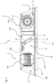
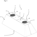
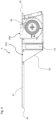
- the present invention relates to an air treatment device referenced with the digit 1.
- the air treatment device 1 is configured to be connected to a ceiling or to a wall.
- the air treatment device 1 is configured to be installed above a hob. Therefore, when installed, the air treatment device 1 faces a hob, at least in part.
- the air treatment device 1 in accordance with the present invention, comprises a casing 2 of predetermined length, width and depth.
- Such casing 2 has a plurality of sides defining a volume 20.
- the casing 2 takes the form of a box-like body.
- Such box-like body is bounded at the bottom, top and sides by the previously mentioned plurality of sides.
- the casing 2 takes the form of a frame not necessarily having closed sides.
- the casing 2 is prism shaped, for example trapezoidal prism shaped.
- the air treatment device 1 comprises a hood module 3 configured to suck in cooking fumes.
- the hood module 3 comprises first suction means 31 to suck in cooking fumes.
- the air treatment device 1 comprises a purifier module 4 configured to purify the air surrounding the air treatment device 1.
- the purifier module 4 comprises first filtering means 41 for filtering air from an environment surrounding the air treatment device 1.
- the first filter means 41 comprise a HEPA filter.
- the purifier module 4 further comprises second suction means 42 for sucking in air from the environment surrounding the air treatment device 1.
- hood module 3 and the purifier module 4 are both housed in the volume 20 of the casing 2.
- the hood module 3 and the purifier module 4 respectively comprise a first support and a second support (not shown in the attached Figures), which can be connected to the casing 2.
- Such supports take the form of a support element to which the various functional elements of the hood module 3 or the purifier module 4 are connected, for example, the first suction means 31, the first filter means 41 and the second suction means 42.
- the supports may be distinct elements or, according to a preferred embodiment, shown in Figure 4 , may correspond to a single support element 17 for the hood module 3 and the purifier module 4 comprising respective housings for the respective functional elements.
- the air treatment device 1 comprises a first inlet opening 5 provided in a first side 211 of the plurality of sides of the casing 2.
- This first side 211 is preferably the lower side of the casing 2.
- the hood module 3 comprises a first suction inlet 310 of said cooking fumes in fluid communication with the first inlet opening 5.
- This first suction inlet 310 is preferably located in the first support.
- the first suction means 31 are placed downstream of the first suction inlet 310.
- the air treatment device 1 further comprises a second inlet opening 7.
- This second inlet opening 7 is located on a second side 212 of the casing 2.
- This second side 212 is in particular distinct from the first side 211.
- the first inlet opening 5 and the second inlet opening 7 are separate from each other and do not lie on the same side.
- the first side 211 and the second side 212 are opposite to one another.
- said second side 212 is the upper side of the casing 2.
- the first side 211 faces the hob and the second side 212 is opposite the hob.
- the arrangement of the first and second suction openings on opposite sides of the casing has the significant technical effect of preventing part of the cooking fumes from being accidentally sucked out of the purifier module, compromising the effectiveness over time of the HEPA filter, which is sensitive to moisture.
- the air treatment device 1 is configured to be connected to a ceiling at the top 212. Accordingly, the air treatment device 1 comprises, for example, connecting elements 15 connected to and extending away from the second side 212. These connecting elements 15 can be connected to a ceiling and are configured to keep the air treatment device 1 hanging therefrom.
- the purifier module 4 comprises a second air suction inlet 410 in fluid communication with the second inlet opening 7. This second suction inlet 410 is located in the second support.
- the first suction inlet 310 and the suction inlet 410 are separate from each other.
- the first filtering means 41 are arranged between the second inlet opening 7 and the second suction inlet 410.
- the second suction means 42 are placed downstream of the second suction inlet 410 and the first filter means 41.
- the air is conveyed by the second suction means 42 through the first filter means 41.
- the hood module 3 and the purifier module 4 are hydrodynamically separated.
- the volume 20 comprises two portions 11, 12.
- a first portion 11 is dimensioned to house the hood module 3, and a second portion 12 is dimensioned to house the purifier module 4.
- the partition septum 10 is part of the second support of the purifier module 4. Accordingly, the hood module 3 is bounded laterally by the partition septum 10 of the purifier module 4.
- the second inlet opening 7 defines an opening surface 71 such as to allow the extraction, through the opening surface 71, of the first filtering means 41.
- said opening surface 71 is shaped so as to be oversized with respect to the first filtering means 41.
- the hood module 3 comprises a first ejection outlet 320 in fluid communication with a first outlet opening 8 arranged on one of the sides of the plurality of sides of the casing 2 distinct from the first side 211.
- the casing 2 comprises the first outlet opening 8, which is placed on any side other than the first side 211.
- the hood module 3 can encompass a hood of the type known as a filtering or suction hood.
- the hood module 3 is connected to air vent at the first ejection outlet 320.
- the first outlet opening 8 is hydrodynamically connected to an air vent configured to transport the extracted cooking fumes to environment other than that facing the air treatment device 1.
- the first outlet opening 8 is in fluid communication with the environment in which the air treatment device 1 is located.
- the purifier module 4 comprises a second ejection outlet 420 in fluid communication with a second outlet opening 9 arranged on one of the sides of the plurality of sides of the casing 2 distinct from the first side 211.
- the first outlet opening 8 and the second outlet opening 9 are arranged on the same side 212 of the plurality of sides of the casing 2, where this side 212 is distinguished from the first side 211.
- the second suction inlet 410, the first ejection outlet 320 and the second ejection outlet 420 are placed on the same side of the casing 2, hence the second side 212.
- the second suction inlet 410 remains separate from the hob, and in this way the vapours issuing from the hob do not reach the second suction inlet 410, thereby ensuring that the first filtering means 41 do not come into contact with these vapours.
- the purifier module 4 comprises third filtering means 43.
- Said third filtering means 43 are arranged between the second ejection outlet 420 and the second outlet opening 9.
- the hood module 3 comprises fourth filtering means 32.
- Said fourth filtering means 32 are arranged between the first ejection outlet 320 and the first outlet opening 8.
- the third filtering means 43 and fourth filtering means 32 respectively comprise an active carbon filter.
- the air treatment device 1 also comprises cover grilles 19 placed at the first and second ejection outlets 320, 420.
- the air treatment device 1 comprises an electronic and/or electromechanical unit 13 configured to control the operation of the hood module 3 and the purifier module 4.
- said electronic unit 13 is housed in the volume 20.
- the air treatment device 1 comprises a control panel 14 associated with the casing 2 externally to the volume 20.
- the control panel 14 is accessible to a user.
- the control panel 14 is in signal communication with the electronic unit 13 and is configured to control the electronic unit 13.
- the control panel 14 comprises, for example, a touch screen or keys that can be pressed by a user to activate the hood module 3 and/or the purifier module 4.
- the electronic unit 13 is placed at the partition septum 10.
- the electronic unit 13 is housed in the first portion 11 of the volume 20.
- control panel 14 and/or the electronic unit 13 are configured to activate the hood module 3 and the purifier module 4 separately.
- the hood module 3 and the purifier module 4 are configured to operate separately and not jointly.
- the air circulating in the hood module 3 remains separated from the air circulating in the purifier module 4.
Landscapes
- Engineering & Computer Science (AREA)
- Chemical & Material Sciences (AREA)
- Combustion & Propulsion (AREA)
- Mechanical Engineering (AREA)
- General Engineering & Computer Science (AREA)
- Filtering Of Dispersed Particles In Gases (AREA)
- Separation By Low-Temperature Treatments (AREA)
- Massaging Devices (AREA)
Claims (12)
- Luftbehandlungsvorrichtung (1), umfassend:- ein Gehäuse (2) vorbestimmter Länge, Breite und Tiefe, das eine Vielzahl von Seiten aufweist, die ein Volumen (20) definieren;- ein Haubenmodul (3), umfassend erste Saugeinrichtungen (31) zum Ansaugen von Kochdämpfen;- ein Reinigungsmodul (4), umfassend erste Filtereinrichtungen (41) zum Filtern von Luft aus einer Umgebung, die die Vorrichtung (1) umgibt, und zweite Ansaugeinrichtungen (42) zum Ansaugen der Luft aus der Umgebung, die die Vorrichtung (1) umgibt, wobei das Haubenmodul (3) und das Reinigungsmodul (4) in dem Volumen (20) des Gehäuses (2) untergebracht sind;- eine erste Einlassöffnung (5), die in einer ersten Seite (211) der Vielzahl von Seiten des Gehäuses (2) bereitgestellt ist, das Haubenmodul (3) umfassend einen ersten Saugeinlass (310) der Kochdämpfe in Fluidverbindung mit der ersten Einlassöffnung (5);- zweite Filtereinrichtungen (6), die an der ersten Einlassöffnung (5) angeordnet sind;- eine zweite Einlassöffnung (7), die in einer zweiten Seite (212) des Gehäuses (2) bereitgestellt ist, die sich von der ersten Seite (211) unterscheidet; das Reinigungsmodul (4) umfassend einen zweiten Saugeinlass (410) der Luft in Fluidverbindung mit der zweiten Einlassöffnung (7), wobei erste Filtereinrichtungen (41) zwischen der zweiten Einlassöffnung (7) und dem zweiten Saugeinlass (410) angeordnet sind;dadurch gekennzeichnet, dass die erste Seite (211) und die zweite Seite (212) einander gegenüber sind.
- Vorrichtung (1) nach Anspruch 1, wobei:- das Haubenmodul (3) einen ersten Ausstoßauslass (320) in Fluidverbindung mit einer ersten Auslassöffnung (8) umfasst, die in einer der Seiten der Vielzahl von Seiten des Gehäuses (2) angeordnet ist, die sich von der ersten Seite (211) unterscheidet,- das Reinigungsmodul (4) einen zweiten Ausstoßauslass (420) in Fluidverbindung mit einer zweiten Auslassöffnung (9) umfasst, die in einer der Seiten der Vielzahl von Seiten des Gehäuses (2) angeordnet ist, die sich von der ersten Seite (211) unterscheidet.
- Vorrichtung (1) nach Anspruch 2, wobei die erste Auslassöffnung (8) und die zweite Auslassöffnung (9) auf derselben Seite (212) der Vielzahl von Seiten des Gehäuses (2) angeordnet sind, die sich von der ersten Seite (211) unterscheidet.
- Vorrichtung (1) nach Anspruch 1, umfassend ein Teilungsseptum (10), das innerhalb des Volumens (20) angeordnet ist, wobei das Teilungsseptum (10) konfiguriert ist, um das Volumen (20) in zwei hermetisch getrennte Abschnitte (11, 12) zu unterteilen, wobei ein erster Abschnitt (11) dimensioniert ist, um das Haubenmodul (3) unterzubringen, und ein zweiter Abschnitt (12) dimensioniert ist, um das Reinigungsmodul (4) unterzubringen.
- Vorrichtung (1) nach Anspruch 4, wobei das Haubenmodul (3), das Reinigungsmodul (4) und das Teilungsseptum (10) zumindest auf der zweiten Seite (212) mechanisch an das Gehäuse (2) gebunden sind.
- Vorrichtung (1) nach Anspruch 1, umfassend:- eine elektronische Einheit (13), die konfiguriert ist, um den Betrieb des Haubenmoduls (3) und des Reinigungsmoduls (4) zu steuern, wobei die elektronische Einheit (13) in dem Volumen (20) untergebracht ist;- ein Bedienfeld (14), das mit dem Gehäuse (2) außerhalb des Volumens (20) assoziiert ist, wobei das Bedienfeld (14) konfiguriert ist, um die elektronische Einheit (13) zu steuern.
- Vorrichtung (1) nach den Ansprüchen 4 und 6, wobei die elektronische Einheit (13) in dem ersten Abschnitt (11) des Volumens (20) untergebracht ist.
- Vorrichtung (1) nach Anspruch 6, wobei das Bedienfeld (14) und/oder die elektronische Einheit (13) konfiguriert sind, um alternativ das Haubenmodul (3) und das Reinigungsmodul (4) zu aktivieren.
- Vorrichtung (1) nach Anspruch 1, wobei das Reinigungsmodul (4) dritte Filtereinrichtungen (43) umfasst, die zwischen dem zweiten Ausstoßauslass (420) und der zweiten Auslassöffnung (9) angeordnet sind.
- Vorrichtung (1) nach Anspruch 1, wobei die zweite Einlassöffnung (7) eine Öffnungsfläche (71) definiert, um die Extraktion der ersten Filtereinrichtungen (41) des Reinigungsmoduls (4) durch die Öffnungsfläche (71) zu ermöglichen.
- Vorrichtung (1) nach Anspruch 1, wobei das Haubenmodul (3) vierte Filtereinrichtungen (32) umfasst, die zwischen dem ersten Ausstoßauslass (320) und der ersten Auslassöffnung (8) angeordnet sind.
- Vorrichtung (1) nach einem der vorherigen Ansprüche, wobei die ersten Filtereinrichtungen (41) einen HEPA-Filter umfassen, die zweiten Filtereinrichtungen (6) einen Fettfilter umfassen und die dritten Filtereinrichtungen (43) und vierten Filtereinrichtungen (32) einen Aktivkohlefilter umfassen.
Applications Claiming Priority (1)
| Application Number | Priority Date | Filing Date | Title |
|---|---|---|---|
| IT102021000007526A IT202100007526A1 (it) | 2021-03-26 | 2021-03-26 | Dispositivo per il trattamento dell’aria |
Publications (3)
| Publication Number | Publication Date |
|---|---|
| EP4067754A1 EP4067754A1 (de) | 2022-10-05 |
| EP4067754B1 true EP4067754B1 (de) | 2025-06-11 |
| EP4067754C0 EP4067754C0 (de) | 2025-06-11 |
Family
ID=76523316
Family Applications (1)
| Application Number | Title | Priority Date | Filing Date |
|---|---|---|---|
| EP22164216.8A Active EP4067754B1 (de) | 2021-03-26 | 2022-03-24 | Vorrichtung zur luftbehandlung |
Country Status (2)
| Country | Link |
|---|---|
| EP (1) | EP4067754B1 (de) |
| IT (1) | IT202100007526A1 (de) |
Family Cites Families (6)
| Publication number | Priority date | Publication date | Assignee | Title |
|---|---|---|---|---|
| KR200212775Y1 (ko) * | 1998-07-09 | 2001-02-15 | 김기영 | 형광등 소켓 |
| CN1220848C (zh) * | 2003-05-20 | 2005-09-28 | 徐剑光 | 具有制冷、空气净化处理功能的抽油烟机 |
| JP6929035B2 (ja) * | 2016-09-20 | 2021-09-01 | 株式会社ノーリツ | レンジフード |
| EP3532776B1 (de) * | 2016-10-25 | 2020-12-23 | PlasmaMade B.V. | Filtersystem zum filtern eines stroms, dunstabzugshaube mit solch einem filter und verfahren zum filtern von luft |
| KR102093869B1 (ko) * | 2018-10-31 | 2020-03-26 | 김대용 | 공기정화기가 일체로 구비된 렌지 후드 |
| KR20200002647U (ko) * | 2019-05-27 | 2020-12-08 | 칭다오 바이탈 인텔리젼트 일렉트릭 어플라이언스 코., 엘티디. | 조명겸용 공기청정기 |
-
2021
- 2021-03-26 IT IT102021000007526A patent/IT202100007526A1/it unknown
-
2022
- 2022-03-24 EP EP22164216.8A patent/EP4067754B1/de active Active
Also Published As
| Publication number | Publication date |
|---|---|
| IT202100007526A1 (it) | 2022-09-26 |
| EP4067754C0 (de) | 2025-06-11 |
| EP4067754A1 (de) | 2022-10-05 |
Similar Documents
| Publication | Publication Date | Title |
|---|---|---|
| EP3380791B1 (de) | Haube für den hausgebrauch | |
| EP3390918B1 (de) | Abzugshaube für den haushaltsgebrauch | |
| US11885505B2 (en) | Filter device and fume extraction device comprising filter device | |
| US10704557B2 (en) | Suction device for a range hood comprising a volute including a first semi-shell and a second semi-shell forming a compartment for housing a capacitor and a connector electrically coupled to an electric motor | |
| EP2610555B1 (de) | Dunstabzugshaube mit einem Fettfilter | |
| EP4067754B1 (de) | Vorrichtung zur luftbehandlung | |
| EP2610556A2 (de) | Geruchsfilter für eine Dunstabzugshaube und jeweilige Dunstabzugshaube | |
| EP3163175B1 (de) | Filterhaube mit dem lüfter zugewandten filter | |
| EP2090834A1 (de) | Einzelblockstruktur einer Absaughaube | |
| JP3224756U (ja) | 排気脱臭装置用プレフィルター | |
| US20020134371A1 (en) | Oven mounted hood assembly for evacuating heat and airborne particulates | |
| US3538839A (en) | Stove exhaust assembly | |
| CN111780173A (zh) | 家用电器 | |
| IT201800007763A1 (it) | Unita' per l'aspirazione dei fumi e vapori prodotti durante le operazioni di cottura di cibi e pietanze | |
| EP2839220A1 (de) | Geruchsfilter für eine dunstabzugshaube und zugehörige dunstabzugshaube | |
| WO2001037972A3 (en) | Modular filtration device for extractor and/or filtering hoods | |
| CN210219909U (zh) | 油烟处理通道构建组件、处理箱、处理装置及炒菜机 | |
| CN217178679U (zh) | 过滤装置及集成灶 | |
| CN222012046U (zh) | 一种净化油烟形成气帘的超薄油烟机 | |
| CN221403154U (zh) | 吸油烟机 | |
| CN217274355U (zh) | 抽油烟机 | |
| CN209807579U (zh) | 一种书柜 | |
| CN210219910U (zh) | 油烟冷却净化处理装置及智能炒菜机 | |
| CN208832542U (zh) | 一种集烟罩组件及油烟机 | |
| JP2612943B2 (ja) | レンジフード |
Legal Events
| Date | Code | Title | Description |
|---|---|---|---|
| PUAI | Public reference made under article 153(3) epc to a published international application that has entered the european phase |
Free format text: ORIGINAL CODE: 0009012 |
|
| STAA | Information on the status of an ep patent application or granted ep patent |
Free format text: STATUS: THE APPLICATION HAS BEEN PUBLISHED |
|
| AK | Designated contracting states |
Kind code of ref document: A1 Designated state(s): AL AT BE BG CH CY CZ DE DK EE ES FI FR GB GR HR HU IE IS IT LI LT LU LV MC MK MT NL NO PL PT RO RS SE SI SK SM TR |
|
| STAA | Information on the status of an ep patent application or granted ep patent |
Free format text: STATUS: REQUEST FOR EXAMINATION WAS MADE |
|
| 17P | Request for examination filed |
Effective date: 20230328 |
|
| RBV | Designated contracting states (corrected) |
Designated state(s): AL AT BE BG CH CY CZ DE DK EE ES FI FR GB GR HR HU IE IS IT LI LT LU LV MC MK MT NL NO PL PT RO RS SE SI SK SM TR |
|
| RIC1 | Information provided on ipc code assigned before grant |
Ipc: F24F 13/20 20060101ALN20241118BHEP Ipc: F24F 13/28 20060101ALI20241118BHEP Ipc: F24C 15/20 20060101AFI20241118BHEP |
|
| GRAP | Despatch of communication of intention to grant a patent |
Free format text: ORIGINAL CODE: EPIDOSNIGR1 |
|
| STAA | Information on the status of an ep patent application or granted ep patent |
Free format text: STATUS: GRANT OF PATENT IS INTENDED |
|
| INTG | Intention to grant announced |
Effective date: 20250103 |
|
| GRAS | Grant fee paid |
Free format text: ORIGINAL CODE: EPIDOSNIGR3 |
|
| GRAA | (expected) grant |
Free format text: ORIGINAL CODE: 0009210 |
|
| STAA | Information on the status of an ep patent application or granted ep patent |
Free format text: STATUS: THE PATENT HAS BEEN GRANTED |
|
| AK | Designated contracting states |
Kind code of ref document: B1 Designated state(s): AL AT BE BG CH CY CZ DE DK EE ES FI FR GB GR HR HU IE IS IT LI LT LU LV MC MK MT NL NO PL PT RO RS SE SI SK SM TR |
|
| REG | Reference to a national code |
Ref country code: GB Ref legal event code: FG4D |
|
| REG | Reference to a national code |
Ref country code: CH Ref legal event code: EP |
|
| REG | Reference to a national code |
Ref country code: IE Ref legal event code: FG4D |
|
| REG | Reference to a national code |
Ref country code: DE Ref legal event code: R096 Ref document number: 602022015704 Country of ref document: DE |
|
| U01 | Request for unitary effect filed |
Effective date: 20250710 |
|
| U07 | Unitary effect registered |
Designated state(s): AT BE BG DE DK EE FI FR IT LT LU LV MT NL PT RO SE SI Effective date: 20250717 |
|
| PG25 | Lapsed in a contracting state [announced via postgrant information from national office to epo] |
Ref country code: ES Free format text: LAPSE BECAUSE OF FAILURE TO SUBMIT A TRANSLATION OF THE DESCRIPTION OR TO PAY THE FEE WITHIN THE PRESCRIBED TIME-LIMIT Effective date: 20250611 |
|
| PG25 | Lapsed in a contracting state [announced via postgrant information from national office to epo] |
Ref country code: GR Free format text: LAPSE BECAUSE OF FAILURE TO SUBMIT A TRANSLATION OF THE DESCRIPTION OR TO PAY THE FEE WITHIN THE PRESCRIBED TIME-LIMIT Effective date: 20250912 Ref country code: NO Free format text: LAPSE BECAUSE OF FAILURE TO SUBMIT A TRANSLATION OF THE DESCRIPTION OR TO PAY THE FEE WITHIN THE PRESCRIBED TIME-LIMIT Effective date: 20250911 |
|
| PG25 | Lapsed in a contracting state [announced via postgrant information from national office to epo] |
Ref country code: HR Free format text: LAPSE BECAUSE OF FAILURE TO SUBMIT A TRANSLATION OF THE DESCRIPTION OR TO PAY THE FEE WITHIN THE PRESCRIBED TIME-LIMIT Effective date: 20250611 |
|
| PG25 | Lapsed in a contracting state [announced via postgrant information from national office to epo] |
Ref country code: RS Free format text: LAPSE BECAUSE OF FAILURE TO SUBMIT A TRANSLATION OF THE DESCRIPTION OR TO PAY THE FEE WITHIN THE PRESCRIBED TIME-LIMIT Effective date: 20250911 |
|
| PG25 | Lapsed in a contracting state [announced via postgrant information from national office to epo] |
Ref country code: IS Free format text: LAPSE BECAUSE OF FAILURE TO SUBMIT A TRANSLATION OF THE DESCRIPTION OR TO PAY THE FEE WITHIN THE PRESCRIBED TIME-LIMIT Effective date: 20251011 |
|
| PG25 | Lapsed in a contracting state [announced via postgrant information from national office to epo] |
Ref country code: SM Free format text: LAPSE BECAUSE OF FAILURE TO SUBMIT A TRANSLATION OF THE DESCRIPTION OR TO PAY THE FEE WITHIN THE PRESCRIBED TIME-LIMIT Effective date: 20250611 |
|
| PG25 | Lapsed in a contracting state [announced via postgrant information from national office to epo] |
Ref country code: CZ Free format text: LAPSE BECAUSE OF FAILURE TO SUBMIT A TRANSLATION OF THE DESCRIPTION OR TO PAY THE FEE WITHIN THE PRESCRIBED TIME-LIMIT Effective date: 20250611 |
|
| PG25 | Lapsed in a contracting state [announced via postgrant information from national office to epo] |
Ref country code: PL Free format text: LAPSE BECAUSE OF FAILURE TO SUBMIT A TRANSLATION OF THE DESCRIPTION OR TO PAY THE FEE WITHIN THE PRESCRIBED TIME-LIMIT Effective date: 20250611 |
|
| PG25 | Lapsed in a contracting state [announced via postgrant information from national office to epo] |
Ref country code: SK Free format text: LAPSE BECAUSE OF FAILURE TO SUBMIT A TRANSLATION OF THE DESCRIPTION OR TO PAY THE FEE WITHIN THE PRESCRIBED TIME-LIMIT Effective date: 20250611 |
|
| PGFP | Annual fee paid to national office [announced via postgrant information from national office to epo] |
Ref country code: GB Payment date: 20260324 Year of fee payment: 5 |
|
| PLBE | No opposition filed within time limit |
Free format text: ORIGINAL CODE: 0009261 |
|
| STAA | Information on the status of an ep patent application or granted ep patent |
Free format text: STATUS: NO OPPOSITION FILED WITHIN TIME LIMIT |
|
| U20 | Renewal fee for the european patent with unitary effect paid |
Year of fee payment: 5 Effective date: 20260318 |
|
| REG | Reference to a national code |
Ref country code: CH Ref legal event code: L10 Free format text: ST27 STATUS EVENT CODE: U-0-0-L10-L00 (AS PROVIDED BY THE NATIONAL OFFICE) Effective date: 20260423 |