EP4066221B1 - Scanner zur unterscheidung von objekten hinter einer opaken oberfläche - Google Patents
Scanner zur unterscheidung von objekten hinter einer opaken oberfläche Download PDFInfo
- Publication number
- EP4066221B1 EP4066221B1 EP20892607.1A EP20892607A EP4066221B1 EP 4066221 B1 EP4066221 B1 EP 4066221B1 EP 20892607 A EP20892607 A EP 20892607A EP 4066221 B1 EP4066221 B1 EP 4066221B1
- Authority
- EP
- European Patent Office
- Prior art keywords
- region
- estimated
- sensors
- opaque surface
- sensor data
- Prior art date
- Legal status (The legal status is an assumption and is not a legal conclusion. Google has not performed a legal analysis and makes no representation as to the accuracy of the status listed.)
- Active
Links
Images


Classifications
-
- G—PHYSICS
- G01—MEASURING; TESTING
- G01N—INVESTIGATING OR ANALYSING MATERIALS BY DETERMINING THEIR CHEMICAL OR PHYSICAL PROPERTIES
- G01N33/00—Investigating or analysing materials by specific methods not covered by groups G01N1/00 - G01N31/00
- G01N33/46—Wood
-
- G—PHYSICS
- G01—MEASURING; TESTING
- G01D—MEASURING NOT SPECIALLY ADAPTED FOR A SPECIFIC VARIABLE; ARRANGEMENTS FOR MEASURING TWO OR MORE VARIABLES NOT COVERED IN A SINGLE OTHER SUBCLASS; TARIFF METERING APPARATUS; MEASURING OR TESTING NOT OTHERWISE PROVIDED FOR
- G01D5/00—Mechanical means for transferring the output of a sensing member; Means for converting the output of a sensing member to another variable where the form or nature of the sensing member does not constrain the means for converting; Transducers not specially adapted for a specific variable
- G01D5/02—Mechanical means for transferring the output of a sensing member; Means for converting the output of a sensing member to another variable where the form or nature of the sensing member does not constrain the means for converting; Transducers not specially adapted for a specific variable using mechanical means
- G01D5/06—Mechanical means for transferring the output of a sensing member; Means for converting the output of a sensing member to another variable where the form or nature of the sensing member does not constrain the means for converting; Transducers not specially adapted for a specific variable using mechanical means acting through a wall or enclosure, e.g. by bellows, by magnetic coupling
-
- G—PHYSICS
- G01—MEASURING; TESTING
- G01D—MEASURING NOT SPECIALLY ADAPTED FOR A SPECIFIC VARIABLE; ARRANGEMENTS FOR MEASURING TWO OR MORE VARIABLES NOT COVERED IN A SINGLE OTHER SUBCLASS; TARIFF METERING APPARATUS; MEASURING OR TESTING NOT OTHERWISE PROVIDED FOR
- G01D5/00—Mechanical means for transferring the output of a sensing member; Means for converting the output of a sensing member to another variable where the form or nature of the sensing member does not constrain the means for converting; Transducers not specially adapted for a specific variable
- G01D5/12—Mechanical means for transferring the output of a sensing member; Means for converting the output of a sensing member to another variable where the form or nature of the sensing member does not constrain the means for converting; Transducers not specially adapted for a specific variable using electric or magnetic means
- G01D5/14—Mechanical means for transferring the output of a sensing member; Means for converting the output of a sensing member to another variable where the form or nature of the sensing member does not constrain the means for converting; Transducers not specially adapted for a specific variable using electric or magnetic means influencing the magnitude of a current or voltage
- G01D5/24—Mechanical means for transferring the output of a sensing member; Means for converting the output of a sensing member to another variable where the form or nature of the sensing member does not constrain the means for converting; Transducers not specially adapted for a specific variable using electric or magnetic means influencing the magnitude of a current or voltage by varying capacitance
-
- G—PHYSICS
- G01—MEASURING; TESTING
- G01N—INVESTIGATING OR ANALYSING MATERIALS BY DETERMINING THEIR CHEMICAL OR PHYSICAL PROPERTIES
- G01N27/00—Investigating or analysing materials by the use of electric, electrochemical, or magnetic means
- G01N27/72—Investigating or analysing materials by the use of electric, electrochemical, or magnetic means by investigating magnetic variables
-
- G—PHYSICS
- G01—MEASURING; TESTING
- G01R—MEASURING ELECTRIC VARIABLES; MEASURING MAGNETIC VARIABLES
- G01R29/00—Arrangements for measuring or indicating electric quantities not covered by groups G01R19/00 - G01R27/00
- G01R29/08—Measuring electromagnetic field characteristics
- G01R29/0807—Measuring electromagnetic field characteristics characterised by the application
- G01R29/0814—Field measurements related to measuring influence on or from apparatus, components or humans, e.g. in ESD, EMI, EMC, EMP testing, measuring radiation leakage; detecting presence of micro- or radiowave emitters; dosimetry; testing shielding; measurements related to lightning
- G01R29/085—Field measurements related to measuring influence on or from apparatus, components or humans, e.g. in ESD, EMI, EMC, EMP testing, measuring radiation leakage; detecting presence of micro- or radiowave emitters; dosimetry; testing shielding; measurements related to lightning for detecting presence or location of electric lines or cables
-
- G—PHYSICS
- G01—MEASURING; TESTING
- G01V—GEOPHYSICS; GRAVITATIONAL MEASUREMENTS; DETECTING MASSES OR OBJECTS; TAGS
- G01V3/00—Electric or magnetic prospecting or detecting; Measuring magnetic field characteristics of the earth, e.g. declination, deviation
- G01V3/15—Electric or magnetic prospecting or detecting; Measuring magnetic field characteristics of the earth, e.g. declination, deviation specially adapted for use during transport, e.g. by a person, vehicle or boat
-
- G—PHYSICS
- G01—MEASURING; TESTING
- G01N—INVESTIGATING OR ANALYSING MATERIALS BY DETERMINING THEIR CHEMICAL OR PHYSICAL PROPERTIES
- G01N27/00—Investigating or analysing materials by the use of electric, electrochemical, or magnetic means
- G01N27/02—Investigating or analysing materials by the use of electric, electrochemical, or magnetic means by investigating impedance
- G01N27/22—Investigating or analysing materials by the use of electric, electrochemical, or magnetic means by investigating impedance by investigating capacitance
- G01N27/223—Investigating or analysing materials by the use of electric, electrochemical, or magnetic means by investigating impedance by investigating capacitance for determining moisture content, e.g. humidity
Definitions
- the present invention relates to the field of scanners for differentiating one or more objects detected behind an opaque surface.
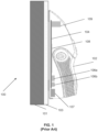
- FIG. 1 illustrates a side view of a conventional scanner.
- a scanner 102 may be used in a construction and home improvement environment 100.
- scanner 102 may be configured to detect an object 101 behind an opaque surface 103.
- object 101 may be a stud, an electrical wire, or a metal pipe.
- the stud may be a wooden stud, vertical wooden element, bridging block, fire block, or any other block, joists, rafters, headers, posts, columns, let brace, or any similar wooden element used for integrity, fabrication, or maintenance of a structural element.
- opaque surface 103 may be, for example, a wall covered with drywall, particle board, or plywood; as an example, a floor with opaque material attached to structural members; as an example, a ceiling with an opaque surface, attached to rafters; or any other opaque surface behind which objects are not visible through the surface.
- scanner 102 may include a housing to enclose and protect various electronic components.
- a housing within the housing of the scanner 102, it may include a printed circuit board (PCB) 104, which can be configured to hold the various electronic components, such as one or more capacitive sensor(s) 108, one or more metal sensors 109, one or more current sensors (not shown), a controller/processor and other integrated circuits (labelled as 106a and 106b).
- the PCB 104 may be coupled to a battery 107, which provides power to the scanner 102.
- the one or more capacitive sensor(s) 108, one or more metal sensors 109, and one or more current sensors are typically operated individually or separately. However, such conventional applications may be insufficient to address the complexity of differentiating one or more objects behind the opaque surface 103.
- the display that receives the display signal shows the location and/or size and/or depth of the foreign object.
- a procedure, computer-executed step, logic block, process, etc. is here conceived to be a self-consistent sequence of one or more steps or instructions leading to a desired result.
- the steps are those utilizing physical manipulations of physical quantities. These quantities can take the form of electrical, magnetic, or radio signals capable of being stored, transferred, combined, compared, and otherwise manipulated in a computer system. These signals may be referred to at times as bits, values, elements, symbols, characters, terms, numbers, or the like.
- Each step may be performed by hardware, software, firmware, or combinations thereof.
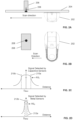
- FIG. 2A illustrates a top view of an exemplary embodiment for differentiating one or more objects detected behind an opaque surface according to aspects of the present invention.
- the exemplary embodiment may include a scanner 202 an opaque surface 204, and one or more objects (labelled as 206, 208) behind the opaque surface 204.
- the scanner 202 may be configured to differentiate a variety of objects detected behind the opaque surface, including but not limited to, for example: 1) wood studs, wood joists, wood rafters; 2) metallic objects; 3) electrical wires; or 4) other objects.
- object 206 may be a wood stud
- object 208 may be a metal pipe
- object 220 may be a current source.
- FIG. 2B illustrates a front view of the exemplary embodiment of FIG. 2A for detecting different objects behind an opaque surface according to aspects of the present invention.
- the opaque surface is not shown for simplicity.
- the scan direction may be from right to left.
- the scan direction may be adjusted based on the working environment, the preference of the user, and the specific application. In other words, the scan direction may be from left to right, right to left, up to down, down to up, or diagonally.
- a user may perform multiple scans and/or from multiple directions to improve the accuracy of sensor data collected.
- FIG. 2C illustrates a first set of sensor data collected by the scanner of FIG. 2B according to aspects of the present invention.
- the sensor data may be collected by one or more capacitive sensors of the scanner 202; and one or more items may be included in a set.
- the signal may represent a change of capacitance due to the change in the density of the objects behind the opaque surface, which may include an indication of the density of object 206 and object 208.
- the vertical axis represents a magnitude of the signal observed by the capacitive sensors, and the horizontal axis represents a distance of the capacitive sensors from the objects being detected.
- the magnitude of the signal being observed by the capacitive sensors increases, reaching a plateau when the scanner is approximately above the center of the objects. As the scanner 202 continues to move pass the center of the objects, the magnitude of the signal being observed by the capacitive sensors decreases.
- a first reference signal strength may be used to identify the boundaries of object 206.
- the region between the two dashed lines 210a and 210b has a signal strength at or above RS 1 , and this region may be estimated to be where object 206 is located.
- the region outside of the two dashed lines 210a and 210b has a signal strength below RS 1 , and this region may be estimated to be where object 206 is not found.
- object 206 behind the opaque surface may be detected and the boundaries of object 206 may be recorded, as indicated by the dashed lines 210a and 210b in FIG. 2C .
- the first reference signal strength RS 1 may be derived from empirical experimental data.
- the first reference signal strength RS 1 may be programmable, and may be revised via a software update even after the scanner has been sold, the delivery methods of which are well known to those skilled in the art.
- the distance D MIN1 represent a minimum distance between the capacitive sensors of the scanner 202 and the approximate center of the objects. Note that although a right to left scan is described in this example, similar observations may be obtained by a scan from left to right. In some applications, multiple scans from different directions may be used to improve the accuracy of the estimated boundaries of object 206.
- FIG. 2D illustrates a second set of sensor data collected by the scanner of FIG. 2B according to aspects of the present invention.
- the sensor data may be collected by one or more metal sensors of scanner 202; and one or more items may be included in a set.
- the signal may represent a magnetic field detected behind the opaque surface, primarily affected by the existence of a metal object, such as object 208.
- the vertical axis represents a magnitude of the signal observed by the metal sensors
- the horizontal axis represents a distance of the metal sensors from object 208.
- the magnitude of the signal being observed by the metal sensors increases, reaching a plateau when the scanner is approximately above the center of object 208.
- the magnitude of the signal being observed by the metal sensors decreases.
- a second reference signal strength may be used to identify the boundaries of object 208.
- the region between the two dashed lines 212a and 212b has a signal strength at or above RS 2 , and this region may be estimated to be where object 208 is located.
- the region outside of the two dashed lines 212a and 212b has a signal strength below RS 2 , and this region may be estimated to be where object 208 is not found.
- the second reference signal strength RS 2 may be derived from empirical experimental data.
- the second reference signal strength RS 2 may be programmable, and may be revised via a software update even after the scanner 202 has been sold, the delivery methods of which are well known to those skilled in the art.
- the distance D MIN2 represents a minimum distance between the metal sensors of scanner 202 and the approximate center of object 208. Note that although a right to left scan is described in this example, similar observations may be obtained by a scan from left to right. In some applications, multiple scans from different directions may be used to improve the accuracy of the estimated boundaries of object 208.
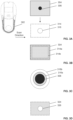
- FIG. 3A illustrates a front view of another exemplary embodiment for detecting different objects behind an opaque surface according to aspects of the present invention.
- the exemplary embodiment may include a scanner 302 and one or more objects (labelled as 304 and 306) behind an opaque surface.
- Object 304 may be a wood stud
- object 306 may be a metal pipe.
- the scan direction may be from left to right.
- the method described above in association with FIG. 2A to FIG. 2D may be employed to determine an estimated region for each object behind the opaque surface, which is not repeated here.
- rectangle 314 represents an estimated region of object 304
- circle 316 represents an estimated region of object 306.
- FIG. 3B illustrates an exemplary method of determining an estimated region of an object of FIG. 3A according to aspects of the present invention.
- the method of determining the estimated region of object 304 is used as an example.
- a first estimated region 314a can be determined by employing the first reference signal strength (RS 1 ) as described in association with FIG. 2C . Since the first reference signal strength may be programmable, for a wood stud, it can be programmed to provide the first estimated region 314a to be smaller than the actual object 304. By choosing the first estimated region 314a to be smaller than the actual object 304, this approach can provide the benefit of having a higher level of confidence that a wood stud is hit when a user drills into the opaque surface.
- RS 1 the first reference signal strength
- a second estimated region 314b can be determined by inserting a safety margin.
- This safety margin is represented by the area between the first estimated region 314a and the second estimated region 314b.
- Various factors may be used to determine the safety margin, including but not limited to: 1) type of material of the opaque surface; 2) humidity of the environment; 3) temperature of the environment; or 4) other factors that may affect the accuracy of determining the estimated region of object 304.
- the safety margin may add 2mm, 4mm, or other measurements on each side of the first estimated region to form the second estimated region based on the above factors and the design criteria for the scanner.
- either the first estimated region 314a or the second estimated region 314b may be used to represent the estimated region of object 304.
- FIG. 3C illustrates another exemplary method of determining an estimated region of another object of FIG. 3A according to aspects of the present invention.
- the method of determining the estimated region of object 306 is used as an example.
- a first estimated region 316a can be determined by employing the second reference signal strength (RS 2 ) as described in association with FIG. 2D .
- the second reference signal strength may be programmable, for a metal pipe, it can be programmed to provide the first estimated region 316a to be larger than the actual object 306, for example larger by 1 millimeter (mm), 3 mm, or other measurements on each side of the first estimated region based on design criteria for the scanner.
- this approach can provide the benefit of having a higher level of confidence that a metal object is missed when the user drills into the opaque surface.
- a second estimated region 316b can be determined by inserting a safety margin.
- This safety margin is represented by the area between the first estimated region 316a and the second estimated region 316b.
- Various factors may be used to determine the safety margin, including but not limited to: 1) type of material of the opaque surface; 2) humidity of the environment; 3) temperature of the environment; or 4) other factors that may affect the accuracy of determining the estimated region of object 306.
- either the first estimated region 316a or the second estimated region 316b may be used to represent the estimated region of object 306.
- FIG. 3D illustrates an exemplary implementation of displaying the estimated regions of the different objects of FIG. 3A according to aspects of the present invention.
- a user interface can mean any form of communication to a user, including, but not limited to, visual (for example via a display or one or more light emitting diodes), audible (for example via a speaker) or sensory (for example via a vibration).
- the information being communicated may be displayed, streamed, stored, mapped, or distributed across multiple devices.
- Communication to the user can mean either the user or any other person or object which can receive communication.
- the method determines regions where a single object is detected as well as regions where multiple objects are detected. In the example shown in FIG.
- metal pipe 326 may represent a region where multiple objects are detected (for example, which region includes part of stud 324), and rectangle 324 (which includes part of metal pipe 326) may represent a region where a part of it has multiple objects (for example, part of metal pipe 326 and part of stud 324) and another part of it (excluding the remainder of metal pipe 326 and the region that includes both stud 324 and metal pipe 326) has a single object.
- the display may be configured to display the multiple objects detected behind the opaque surface for this region.
- the display may be configured to display the single object detected behind the opaque surface.
- the display may be configured to display nothing for the region of metal pipe 326.
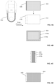
- FIG. 4A illustrates a front view of yet another exemplary embodiment for differentiating one or more objects detected behind an opaque surface according to aspects of the present invention.
- the exemplary embodiment may include a scanner 402, and one or more objects (labelled as 404 and 406) behind an opaque surface.
- Object 404 may be a wood stud
- object 406 may be an electrical wire.
- the scan direction may be from left to right.
- the method described above in association with FIG. 2A to FIG. 2D may be employed to determine an estimated region for each object behind the opaque surface, which is not repeated here.
- rectangle 414 represents an estimated region of object 404
- rectangle 416 represents an estimated region of object 406.
- FIG. 4B illustrates an exemplary method of determining an estimated region of an object of FIG. 4A according to aspects of the present invention.
- the method of determining the estimated region of object 404 is used as an example.
- a first estimated region 414a can be determined by employing the first reference signal strength (RS 1 ) as described in association with FIG. 2C .
- the first reference signal strength may be programmable, for a wood stud, for example, it can be programmed to provide the first estimated region 414a to be smaller than the actual object 404, for example smaller by 2mm, 4mm, or other measurements on each side of the first estimated region based on design criteria for the scanner.
- this approach can provide the benefit of having a higher level of confidence that a wood stud is hit when a user drills into the opaque surface.
- a second estimated region 414b can be determined by inserting a safety margin.
- This safety margin is represented by the area between the first estimated region 414a and the second estimated region 414b.
- Various factors may be used to determine the safety margin, including but not limited to: 1) type of material of the opaque surface; 2) humidity of the environment; 3) temperature of the environment; or 4) other factors that may affect the accuracy of determining the estimated region of object 404.
- either the first estimated region 414a or the second estimated region 414b may be used to represent the estimated region of object 404.
- FIG. 4C illustrates another exemplary method of determining an estimated region of another object of FIG. 4A according to aspects of the present invention.
- the method of determining the estimated region of object 406 is used as an example.
- a first estimated region 416a can be determined by employing a third reference signal strength (RS 3 ) similar to the description in association with FIG. 2D .
- the third reference signal strength may be programmable.
- RS 3 third reference signal strength
- it can be programmed to provide the first estimated region 416a to be larger than the actual object 406, for example larger by 3mm, 5 mm, or other measurements on each side of the first estimated region based on design criteria for the scanner.
- this approach can provide the benefit of having a higher level of confidence that an electrical wire is missed when a user drills into the opaque surface.
- a second estimated region 416b can be determined by inserting a safety margin.
- This safety margin is represented by the area between the first estimated region 416a and the second estimated region 416b.
- Various factors may be used to determine the safety margin, including but not limited to: 1) type of material of the opaque surface; 2) humidity of the environment; 3) temperature of the environment; or 4) other factors that may affect the accuracy of determining the estimated region of object 406.
- the safety margin may add 1mm, 3mm, or other measurements on each side of the first estimated region to form the second estimated region based on the above factors and the design criteria for the scanner.
- either the first estimated region 416a or the second estimated region 416b may be used to represent the estimated region of object 406.
- FIG. 4D illustrates an exemplary implementation of displaying the estimated regions of the different objects of FIG. 4A according to aspects of the present invention.
- the method determines regions where a single object is detected as well as regions where multiple objects are detected.
- rectangle 426 may represent a region where multiple objects are detected
- rectangle 424 (which includes part of rectangle 426) may represent a region where a part of it has multiple objects (for example the region that overlaps with rectangle 426) and another part of it (excluding the region that overlaps with rectangle 426) has a single object.
- the display may be configured to display the multiple objects detected behind the opaque surface for this region.
- the display may be configured to display the single object detected behind the opaque surface.
- the display may be configured to display nothing for the region of the rectangle 426.
- FIG. 5A illustrates a top view of yet another exemplary embodiment for differentiating one or more objects detected behind an opaque surface according to aspects of the present invention.
- the exemplary embodiment may include a scanner 502, an opaque surface 504, and one or more objects (labelled as 506, 508, and 510) behind the opaque surface 504.
- the scanner 502 may be configured to detect a variety of objects behind the opaque surface, including but not limited to: 1) wood studs; 2) metallic objects; 3) electrical wires; or 4) other objects.
- object 506 may be a wood stud
- object 508 may be a metal pipe
- object 510 may be an electrical wire.
- FIG. 5B illustrates a front view of the exemplary embodiment of FIG. 5A for detecting object(s) behind an opaque surface according to aspects of the present invention.
- the opaque surface is not shown for simplicity.
- the scan direction may be from right to left.
- the scan direction may be adjusted based on the working environment, the preference of the user, and the specific application. In other words, the scan direction may be from left to right, right to left, up to down, down to up, or diagonally.
- a user may perform multiple scans and/or from multiple directions to improve the accuracy of sensor data collected.
- FIG. 5C illustrates estimated regions of the different objects of FIG. 5B according to aspects of the present invention. Note that the method of determining an estimated region of an object is described above, for example in association with FIG. 3B and FIG. 3C , which is not repeated here. As shown in FIG. 5C , rectangle 516 represents an estimated region for stud 506, rectangle 518 represents an estimated region for metal pipe 508, and rectangle 520 represents an estimated region for electrical wire 510.
- the estimated region 516 can be configured to be smaller than stud 506, this approach can provide the benefit of having a higher level of confidence that a wood stud 506 is penetrated by a drill bit when a user drills through the opaque surface.
- the estimated region 518 can be configured to be larger than metal pipe 508, this approach can provide the benefit of having a higher level of confidence that metal pipe 508 is missed when a user drills through the opaque surface.
- the estimated region 520 can be configured to be larger than electrical wire 510, this approach can provide the benefit of having a higher level of confidence that electrical wire 510 is missed when a user drills through the opaque surface.
- FIG. 5D illustrates an exemplary implementation of displaying the estimated regions of the different objects of FIG. 5C according to aspects of the present invention.
- the display may be configured to display the estimated region for stud 506, represented by rectangle 526, and display the estimated region for metal pipe 508, represented by rectangle 528, and display the estimated region for electrical wire 510, represented by the rectangle 530.
- the display may be configured to display the region under the rectangle 528 to include both metal pipe 508 and wood stud 506, and display the region under the rectangle 530 to include both electrical wire 510 and wood stud 506.
- FIG. 6A illustrates a top view of an exemplary embodiments for differentiating one or more objects detected behind an opaque surface using sensor data from different sensors according to aspects of the present invention.
- the exemplary embodiment may include a scanner 602, an opaque surface 604, and one or more objects (labelled as 606) behind the opaque surface 604.
- object 606 may be, for example, a metal pipe.
- FIG. 6B illustrates a front view of the exemplary embodiment of FIG. 6A for detecting the object according to aspects of the present invention.
- the opaque surface is not shown for simplicity.
- the scan direction may be from left to right.
- the scan direction may be adjusted based on the working environment, the preference of the user, and the specific application. In other words, the scan direction may be from left to right, right to left, up to down, down to up, or diagonally.
- a user may perform multiple scans and/or from multiple directions to improve the accuracy of sensor data collected.
- FIG. 6C illustrates an exemplary method of determining a distance between the scanner and the object of FIG. 6B according to aspects of the present invention.
- the vertical axis represents a common reference point or a common reference line from which a distance between scanner 602 and metal pipe 606 is estimated.
- the horizontal axis represents a distance from the common reference point or the common reference line.
- Scanner 602 may to configured to collect sensor data as described above in association with FIG. 2C and FIG. 2D . For example, based on the sensor data collected by one or more capacitive sensors of scanner 602, a first distance D 1 , representing a distance between scanner 602 and metal pipe 606, may be estimated by the capacitive sensors.
- a second distance D 2 representing a distance between scanner 602 and metal pipe 606, may be estimated by the metal sensors.
- the metal sensors may provide an estimated distance (e.g. D 2 ) that is shorter than the actual distance between scanner 602 and metal pipe 606.
- the capacitive sensors may provide an estimated distance (e.g. D 1 ) that is closer to the actual distance between scanner 602 and the metal pipe 606.
- scanner 602 may be configured to derive a distance D 3 for metal pipe 606 from the common reference.
- scanner 602 will obtain an improved estimation of the distance between scanner 602 and metal pipe 606 in this example.
- both the sensor data collected by the capacitive sensors and the metal sensors may be collected in parallel in a one-pass scan, or multiple sets of sensor data may be collected by the capacitive sensors and the metal sensors in parallel with multiple passes, respectively.
- FIG. 7A illustrates a top view of an exemplary embodiment for differentiating object(s), here a metal screw 706 and stud 708, detected behind an opaque surface using sensor data from different sensors according to aspects of the present invention.
- the exemplary embodiment may include a scanner 702, an opaque surface 704, and one or more objects (labelled as 706 (metal screw) and 708 (stud)) behind opaque surface 704.
- object 706 may be a metal screw and for example, object 708 may be a wood stud.
- FIG. 7B illustrates a front view of the exemplary embodiment of FIG. 7A for detecting the metal object according to aspects of the present invention.
- the scan direction may be from left to right.
- the scan direction may be adjusted based on the working environment, the preference of the user, and the specific application. In other words, the scan direction may be from left to right, right to left, up to down, down to up, or diagonally.
- a user may perform multiple scans and/or from multiple directions to improve the accuracy of sensor data collected.
- FIG. 7C illustrates an exemplary method of determining a distance between the scanner and the metal object of FIG. 7B (screw 706) according to aspects of the present invention.
- the vertical axis represents a common reference point or a common reference line from which a distance between scanner 702 and metal screw 706 and stud 708 is estimated.
- the horizontal axis represents a distance from the common reference point or the common reference line.
- Scanner 702 may be configured to collect sensor data as described above in association with FIG. 2C and FIG. 2D . For example, based on the sensor data collected by one or more capacitive sensors of scanner 702, a first distance D 1 , representing a distance between scanner 702 and metal screw 706 and stud 708 may be estimated by the capacitive sensors.
- a second distance D 2 representing a distance between scanner 702 and metal screw 706, may be estimated by the metal sensors.
- the capacitive sensors and the metal sensors may provide different estimations with respect to the distance between scanner 702 and metal screw 706 based upon the relative size of the metal screw.
- the metal sensors may provide an estimated distance (e.g. D 2 ) that is different from the actual distance between scanner 702 and metal screw 706.
- the capacitive sensors may provide an estimated distance (e.g. D 1 ) that may be closer to the actual distance between scanner 702 and metal screw 706.
- scanner 702 may be configured to derive a distance D 3 for metal screw 706.
- scanner 702 may be able to obtain an improved estimation of the distance between scanner 702 and metal screw 706 in this example.
- both the sensor data collected by the capacitive sensors and the metal sensors may be collected in parallel in a one-pass scan, or multiple sets of sensor data may be collected by the capacitive sensors and the metal sensors in parallel with multiple passes, respectively.
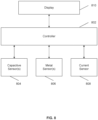
- FIG. 8 illustrates a block diagram of an exemplary embodiment of a system for differentiating one or more objects detected behind an opaque surface using sensor data from different sensors according to aspects of the present invention.
- a controller 802 may be configured to process sensor data collected by sensors of the scanner, namely sensor data collected by capacitive sensors 804, metal sensor 806, and current sensor 808.
- the controller is further configured to determine information about the detected objects behind the opaque surface based on the sensor data collected by capacitive sensors 804, metal sensor 806, and/or current sensor 808 in parallel.
- the controller may include one or more processors.
- a display 810 is configured to provide information about the detected objects to a user.
- the functional blocks described in the system of FIG. 8 may be implemented in an integrated device such as scanner 202 of FIG. 2A .
- the capacitive sensors 804, metal sensors 806, and current sensor 808 may reside in one device, while the controller 802 and the display 810 may reside in another device.
- a scanner device may include the sensors, and the sensor data collected by the scanner device may be wirelessly communicated to a second device.
- the second device for example a smartphone, a tablet, or a laptop, may include the controller 802 and the display 810.
- the controller 802, the capacitive sensors 804, metal sensors 806, and current sensor 808, may reside in one device, while the display 810 may reside in another device.
- a scanner device may include the controller 802 and the sensors, and the sensor data collected by the scanner device may be wirelessly communicated to a second device.
- the second device for example a monitor, may be configured to receive and display the sensor data.
- current sensors may be alternating current sensors. In another exemplary embodiment, current sensors may be able to detect the static magnetic field of or associated with direct current.
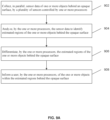
- FIG. 9A illustrates a method of differentiating one or more objects detected behind an opaque surface using sensor data from different sensors according to aspects of the present invention.
- the method collects, in parallel, sensor data of the one or more objects behind an opaque surface, by a plurality of sensors controlled by one or more processors.
- the method analyzes, by the one or more processors, the sensor data to identify estimated regions of the one or more objects behind the opaque surface.
- the method differentiates, by the one or more processors, the estimated regions of the one or more objects behind the opaque surface.
- the method informs a user, by the one or more processors, of the one or more objects within the estimated regions behind the opaque surface.
- the plurality of sensors may include at least a first set of sensors configured to detect a first type of material and a second set of sensors configured to detect a second type of material; and the estimated regions include a first estimated region of the first type of material and a second estimated region of the second type of material.
- the first set of sensors may include one or more capacitive sensors and the first type of material include wood studs; and the second set of sensors may include one or more metal sensors and the second type of material include metal objects.
- the plurality of sensors may further include a third set of sensors configured to detect a third type of material; where the third set of sensors includes one or more current sensors and the third type of material include electrical wires.
- a set of sensors may include one or more sensors in the set.
- the method of collecting sensor data includes mapping the sensor data of the one or more objects behind the opaque surface with respect to a common reference point.
- the method of differentiating the estimated regions of the one or more objects behind the opaque surface includes determining an overlap region between the first estimated region and the second estimated region.
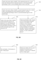
- FIG. 9B illustrates a method of analyzing sensor data to identify estimated regions of the objects detected behind an opaque surface according to aspects of the present invention.
- the method analyzes the sensor data to identify a first measured region for a wood stud, and reducing the first measured region by a first programmable percentage to derive a first estimated region for the wood stud.
- the method analyzes the sensor data to identify a second measured region for a metal object, and enlarging the second measured region by a second programmable percentage to derive a second estimated region for the metal object.
- the methods performed in block 912 and block 914 may additionally or optionally include the methods performed in block 916 and/or block 918.
- the method analyzes the sensor data to identify a third measured region for an electrical wire, and enlarging the third measured region by a third programmable percentage to derive a third estimated region for the electrical wire.
- the method adds programmable safety margins to the corresponding estimated regions in accordance with variations of an operating environment, where the variations of the operating environment include variations in temperature, humidity, material of the opaque surface, or some combination thereof.
- FIG. 9C illustrates a method of informing a user of the objects detected behind an opaque surface according to aspects of the present invention.
- the method described in either block 922 or block 924 may be performed.
- the method prevents display of information in the overlap region.
- the method selectively displays the first type of material, the second type of material, or both types of material in the overlap region.
- the invention can be implemented in any suitable form, including hardware, software, firmware, or any combination of these.
- the invention may optionally be implemented partly as computer software running on one or more data processors and/or digital signal processors, along with the hardware components described above.
- the elements and components of an embodiment of the invention may be physically, functionally, and logically implemented in any suitable way. Indeed, the functionality may be implemented in a single unit, in a plurality of units, or as part of other functional units. As such, the invention may be implemented in a single unit or may be physically and functionally distributed between different units and processors/controllers.
Landscapes
- Physics & Mathematics (AREA)
- General Physics & Mathematics (AREA)
- Life Sciences & Earth Sciences (AREA)
- Chemical & Material Sciences (AREA)
- Health & Medical Sciences (AREA)
- Engineering & Computer Science (AREA)
- Analytical Chemistry (AREA)
- Biochemistry (AREA)
- General Health & Medical Sciences (AREA)
- Immunology (AREA)
- Pathology (AREA)
- Electrochemistry (AREA)
- Chemical Kinetics & Catalysis (AREA)
- Medicinal Chemistry (AREA)
- Food Science & Technology (AREA)
- Wood Science & Technology (AREA)
- Environmental & Geological Engineering (AREA)
- Geology (AREA)
- Remote Sensing (AREA)
- General Life Sciences & Earth Sciences (AREA)
- Geophysics (AREA)
- Electromagnetism (AREA)
- Geophysics And Detection Of Objects (AREA)
- Measurement Of Length, Angles, Or The Like Using Electric Or Magnetic Means (AREA)
Claims (18)
- Ein System zum Unterscheiden eines oder mehrerer Objekte, die hinter einer undurchsichtigen Oberfläche erkannt werden, das Folgendes aufweist:eine Vielzahl von Sensoren (804, 806, 808), die von einem oder mehreren Prozessoren (802) gesteuert werden und so konfiguriert sind, dass sie parallel Sensordaten des einen oder der mehreren Objekte hinter einer undurchsichtigen Oberfläche sammeln;der eine oder die mehreren Prozessoren ferner so konfiguriert sind, dass sie die geschätzten Bereiche des einen oder der mehreren Objekte hinter der undurchsichtigen Oberfläche unterscheiden; undder eine oder die mehreren Prozessoren ferner so konfiguriert sind, dass sie einen Benutzer über eine Benutzerschnittstelle (810) über das eine oder die mehreren Objekte innerhalb der geschätzten Bereiche hinter der undurchsichtigen Oberfläche informieren;dadurch gekennzeichnet, dassder eine oder die mehreren Prozessoren ferner konfiguriert sind, um: die Sensordaten zu analysieren, um einen ersten gemessenen Bereich für einen Holzbalken zu identifizieren, und den ersten gemessenen Bereich um einen ersten programmierbaren Prozentsatz zu reduzieren, um einen ersten geschätzten Bereich für den Holzbalken abzuleiten; und die Sensordaten zu analysieren, um einen zweiten gemessenen Bereich für ein Metallobjekt zu identifizieren, und den zweiten gemessenen Bereich um einen zweiten programmierbaren Prozentsatz zu vergrößern, um einen zweiten geschätzten Bereich für das Metallobjekt abzuleiten.
- System nach Anspruch 1,wobei die Vielzahl von Sensoren mindestens einen ersten Satz von Sensoren, die so konfiguriert sind, dass sie eine erste Art von Material erfassen, und einen zweiten Satz von Sensoren aufweist, die so konfiguriert sind, dass sie eine zweite Art von Material erfassen; undwobei die geschätzten Bereiche einen ersten geschätzten Bereich der ersten Art von Material und einen zweiten geschätzten Bereich der zweiten Art von Material aufweisen.
- System nach Anspruch 2,wobei der erste Satz von Sensoren einen oder mehrere kapazitive Sensoren aufweist und der erste Materialtyp Holzständer aufweist; undwobei der zweite Satz von Sensoren einen oder mehrere Metallsensoren aufweist und der zweite Materialtyp Metallobjekte aufweist.
- System nach Anspruch 2,
wobei die Vielzahl von Sensoren ferner einen dritten Satz von Sensoren aufweist, die so konfiguriert sind, dass sie eine dritte Art von Material erfassen; wobei der dritte Satz von Sensoren einen oder mehrere Stromsensoren aufweist und die dritte Art von Material elektrische Drähte aufweist. - System nach Anspruch 1, wobei der eine oder die mehreren Prozessoren ferner so konfiguriert sind, dass sie:
die Sensordaten des einen oder der mehreren Objekte hinter der undurchsichtigen Oberfläche in Bezug auf einen gemeinsamen Referenzpunkt abbilden. - System nach Anspruch 1, wobei der eine oder die mehreren Prozessoren ferner so konfiguriert sind, dass sie:
die Sensordaten analysieren, um einen dritten gemessenen Bereich für einen elektrischen Draht zu identifizieren, und den dritten gemessenen Bereich um einen dritten programmierbaren Prozentsatz zu vergrößern, um einen dritten geschätzten Bereich für den elektrischen Draht abzuleiten. - System nach Anspruch 1, wobei der eine oder die mehreren Prozessoren ferner so konfiguriert sind, dass sie:
programmierbare Sicherheitsmargen zu den entsprechenden geschätzten Bereichen in Übereinstimmung mit Variationen einer Betriebsumgebung hinzufügen, wobei die Variationen der Betriebsumgebung Variationen in der Temperatur, der Feuchtigkeit, dem Material der undurchsichtigen Oberfläche oder einer Kombination davon aufweisen. - System nach Anspruch 1, wobei der eine oder die mehreren Prozessoren ferner so konfiguriert sind, dass sie:
einen Überlappungsbereich zwischen dem ersten geschätzten Bereich und dem zweiten geschätzten Bereich bestimmen. - System nach Anspruch 8, wobei der eine oder die mehreren Prozessoren ferner so konfiguriert sind, dass sie:die Anzeige von Informationen im Überlappungsbereich verhindern oderden ersten Materialtyp, den zweiten Materialtyp oder beide Materialtypen selektiv im Überlappungsbereich anzeigen.
- Ein Verfahren zum Unterscheiden eines oder mehrerer Objekte, die hinter einer undurchsichtigen Fläche erfasst werden, das Folgendes aufweist:paralleles Erfassen (902) von Sensordaten des einen oder der mehreren Objekte hinter einer undurchsichtigen Fläche durch eine Vielzahl von Sensoren, die durch einen oder mehrere Prozessoren gesteuert werden;Analysieren (904) der Sensordaten durch den einen oder die mehreren Prozessoren, um geschätzte Bereiche des einen oder der mehreren Objekte hinter der undurchsichtigen Fläche zu identifizieren;Unterscheiden (906) der geschätzten Bereiche des einen oder der mehreren Objekte hinter der undurchsichtigen Oberfläche durch den einen oder die mehreren Prozessoren; undInformieren (908) eines Benutzers durch den einen oder die mehreren Prozessoren über eine Benutzerschnittstelle über das eine oder die mehreren Objekte innerhalb der geschätzten Bereiche hinter der undurchsichtigen Oberfläche;dadurch gekennzeichnet, dass es ferner Folgendes aufweist:
Analysieren der Sensordaten, um einen ersten gemessenen Bereich für einen Holzbalken zu identifizieren, und Reduzieren des ersten gemessenen Bereichs um einen ersten programmierbaren Prozentsatz, um einen ersten geschätzten Bereich für den Holzbalken abzuleiten; und Analysieren der Sensordaten, um einen zweiten gemessenen Bereich für ein Metallobjekt zu identifizieren, und Vergrößern des zweiten gemessenen Bereichs um einen zweiten programmierbaren Prozentsatz, um einen zweiten geschätzten Bereich für das Metallobjekt abzuleiten; - Verfahren nach Anspruch 10,wobei die Vielzahl von Sensoren mindestens einen ersten Satz von Sensoren, die so konfiguriert sind, dass sie eine erste Art von Material erfassen, und einen zweiten Satz von Sensoren aufweist, die so konfiguriert sind, dass sie eine zweite Art von Material erfassen; undwobei die geschätzten Bereiche einen ersten geschätzten Bereich der ersten Art von Material und einen zweiten geschätzten Bereich der zweiten Art von Material aufweisen.
- Das Verfahren nach Anspruch 11,wobei der erste Satz von Sensoren einen oder mehrere kapazitive Sensoren aufweist und der erste Materialtyp Holzständer aufweist; undwobei der zweite Satz von Sensoren einen oder mehrere Metallsensoren aufweist und der zweite Materialtyp Metallobjekte aufweist.
- Verfahren nach Anspruch 11,
wobei die Vielzahl von Sensoren ferner einen dritten Satz von Sensoren aufweist, die so konfiguriert sind, dass sie eine dritte Art von Material erfassen; wobei der dritte Satz von Sensoren einen oder mehrere Stromsensoren aufweist und die dritte Art von Material elektrische Drähte aufweist. - Verfahren nach Anspruch 10, wobei das Sammeln von Sensordaten Folgendes aufweist:
Zuordnen der Sensordaten des einen oder der mehreren Objekte hinter der undurchsichtigen Oberfläche in Bezug auf einen gemeinsamen Referenzpunkt. - Das Verfahren nach Anspruch 10, das ferner Folgendes aufweist:
Analysieren der Sensordaten, um einen dritten gemessenen Bereich für einen elektrischen Draht zu identifizieren, und Vergrößern des dritten gemessenen Bereichs um einen dritten programmierbaren Prozentsatz, um einen dritten geschätzten Bereich für den elektrischen Draht abzuleiten. - Das Verfahren nach Anspruch 10, wobei das Analysieren der Sensordaten, um geschätzte Bereiche des einen oder der mehreren Objekte zu identifizieren, ferner Folgendes aufweist:
Hinzufügen programmierbarer Sicherheitsabstände zu den entsprechenden geschätzten Bereichen in Übereinstimmung mit Variationen einer Betriebsumgebung, wobei die Variationen der Betriebsumgebung Variationen in der Temperatur, der Feuchtigkeit, dem Material der undurchsichtigen Oberfläche oder einer Kombination davon aufweisen. - Verfahren nach Anspruch 10, wobei das Unterscheiden aufweist:
Bestimmen eines Überlappungsbereichs zwischen dem ersten geschätzten Bereich und dem zweiten geschätzten Bereich. - Verfahren nach Anspruch 17, wobei das Informieren des Benutzers aufweist:Verhindern der Anzeige von Informationen in dem Überlappungsbereich; oderselektives Anzeigen des ersten Materialtyps, des zweiten Materialtyps oder beider Materialtypen in dem Überlappungsbereich.
Applications Claiming Priority (2)
| Application Number | Priority Date | Filing Date | Title |
|---|---|---|---|
| US16/698,751 US11512978B2 (en) | 2019-11-27 | 2019-11-27 | Scanner for differentiating objects detected behind an opaque surface |
| PCT/US2020/058677 WO2021108091A1 (en) | 2019-11-27 | 2020-11-03 | Scanner for differentiating objects detected behind an opaque surface |
Publications (4)
| Publication Number | Publication Date |
|---|---|
| EP4066221A1 EP4066221A1 (de) | 2022-10-05 |
| EP4066221A4 EP4066221A4 (de) | 2023-12-27 |
| EP4066221B1 true EP4066221B1 (de) | 2025-03-12 |
| EP4066221C0 EP4066221C0 (de) | 2025-03-12 |
Family
ID=75971363
Family Applications (1)
| Application Number | Title | Priority Date | Filing Date |
|---|---|---|---|
| EP20892607.1A Active EP4066221B1 (de) | 2019-11-27 | 2020-11-03 | Scanner zur unterscheidung von objekten hinter einer opaken oberfläche |
Country Status (5)
| Country | Link |
|---|---|
| US (1) | US11512978B2 (de) |
| EP (1) | EP4066221B1 (de) |
| JP (1) | JP7286881B2 (de) |
| CA (1) | CA3152553C (de) |
| WO (1) | WO2021108091A1 (de) |
Families Citing this family (4)
| Publication number | Priority date | Publication date | Assignee | Title |
|---|---|---|---|---|
| US12182837B1 (en) * | 2020-03-25 | 2024-12-31 | United Services Automobile Association (Usaa) | Obtaining and estimating repair or replacement information from a smart building |
| IT202100012395A1 (it) * | 2021-05-13 | 2022-11-13 | St Microelectronics Srl | Circuito controllore, sistema e procedimento corrispondenti |
| WO2023048852A1 (en) * | 2021-09-24 | 2023-03-30 | Zircon Corporation | Scanner for detecting objects behind an opaque surface |
| US12493131B2 (en) * | 2024-04-02 | 2025-12-09 | Zircon Corporation | System and method for detecting objects behind an opaque surface |
Family Cites Families (29)
| Publication number | Priority date | Publication date | Assignee | Title |
|---|---|---|---|---|
| JP2681040B2 (ja) * | 1987-03-16 | 1997-11-19 | 株式会社マイゾックス | 非金属・金属部材探知器 |
| US5352974A (en) | 1992-08-14 | 1994-10-04 | Zircon Corporation | Stud sensor with digital averager and dual sensitivity |
| JPH10123259A (ja) * | 1996-10-17 | 1998-05-15 | Shinko Mecs Kk | 金属板の背後に存在する金属物体の検出方法とその装置 |
| US6215293B1 (en) | 1998-08-12 | 2001-04-10 | Solar Wide Industrial Limited | Portable stud detector for detecting wood, metal, and live wires |
| US20030218469A1 (en) | 2002-02-27 | 2003-11-27 | Brazell Kenneth M. | Multifunctional object sensor |
| US6894508B2 (en) | 2002-06-28 | 2005-05-17 | Solar Wide Industrial Ltd. | Apparatus and method for locating objects behind a wall lining |
| US7495455B2 (en) * | 2002-06-28 | 2009-02-24 | Solar Wide Industrial Limited | Stud sensing device |
| US6933712B2 (en) | 2002-07-15 | 2005-08-23 | Zircon Corporation | Electrical circuit tracing and identifying apparatus and method |
| DE102004007314A1 (de) * | 2004-02-14 | 2005-08-25 | Robert Bosch Gmbh | Verfahren und Messgerät zur Ortung von in einem Medium eingeschlossenen Objekten |
| DE102004007316A1 (de) | 2004-02-14 | 2005-08-25 | Robert Bosch Gmbh | Infrarot-Ortungsgerät mit Merhfachsensorik |
| DE102004012072A1 (de) | 2004-03-12 | 2005-09-29 | Robert Bosch Gmbh | Ortungsgerät |
| US8593157B2 (en) | 2005-02-15 | 2013-11-26 | Walleye Technologies, Inc. | Electromagnetic scanning imager |
| DE102005007803A1 (de) | 2005-02-21 | 2006-08-24 | Robert Bosch Gmbh | Verfahren zur Detektion von in einem Medium eingeschlossenen Objekten sowie Messgerät zur Durchführung des Verfahrens |
| DE102005015326A1 (de) | 2005-04-01 | 2006-10-05 | Robert Bosch Gmbh | Verfahren zur Detektion von in einem Medium eingeschlossenen Objekten sowie Messgerät zur Durchführung des Verfahrens |
| DE102005015325A1 (de) | 2005-04-01 | 2006-10-05 | Robert Bosch Gmbh | Verfahren zur Lokalisierung von in einem Medium eingeschlossenen Objekten, sowie Messgerät zur Durchführung des Verfahrens |
| US7812722B2 (en) | 2007-02-28 | 2010-10-12 | Zircon Corporation | Dual orientation metal scanner |
| US7504817B2 (en) | 2007-03-28 | 2009-03-17 | Solar Wide Industrial Limited | Stud sensor |
| US7977938B2 (en) | 2007-05-04 | 2011-07-12 | Solar Wide Industrial Ltd. | Device and method of detecting ferrite and non-ferrite objects |
| CA2717860C (en) | 2008-03-07 | 2016-11-08 | Milwaukee Electric Tool Corporation | Battery pack for use with a power tool and a non-motorized sensing tool |
| JP2010217131A (ja) | 2009-03-19 | 2010-09-30 | Kawamura Electric Inc | 金属検知装置 |
| WO2011163277A2 (en) | 2010-06-21 | 2011-12-29 | William Alexander Barr | Locating device for use with power tools |
| DE102010039953A1 (de) | 2010-08-30 | 2012-03-01 | Robert Bosch Gmbh | Verfahren zur Lokalisierung von in einem Medium eingeschlossenen Objekten, sowie Messgerät zur Durchführung des Verfahrens |
| DE102011079258A1 (de) * | 2011-07-15 | 2013-01-17 | Hilti Aktiengesellschaft | Verfahren und Vorrichtung zum Detektieren eines Objektes in einem Untergrund |
| US9194950B2 (en) | 2012-01-19 | 2015-11-24 | Black & Decker Inc. | Handheld locating device |
| US10234589B2 (en) * | 2013-01-02 | 2019-03-19 | Zircon Corporation | Surface marking tool |
| US9959591B2 (en) * | 2014-07-31 | 2018-05-01 | Seiko Epson Corporation | Display apparatus, method for controlling display apparatus, and program |
| US20190021631A1 (en) * | 2015-03-09 | 2019-01-24 | Nexus Control Systems, Llc | Method and system for locating material on or inside a patient's body |
| US10663613B2 (en) * | 2015-06-23 | 2020-05-26 | Franklin Sensors, Inc. | Apparatus and methods for detecting obscured features |
| CN111051009B (zh) | 2017-08-30 | 2023-06-16 | 米沃奇电动工具公司 | 具有物体检测的电动工具 |
-
2019
- 2019-11-27 US US16/698,751 patent/US11512978B2/en active Active
-
2020
- 2020-11-03 WO PCT/US2020/058677 patent/WO2021108091A1/en not_active Ceased
- 2020-11-03 EP EP20892607.1A patent/EP4066221B1/de active Active
- 2020-11-03 CA CA3152553A patent/CA3152553C/en active Active
- 2020-11-03 JP JP2022525654A patent/JP7286881B2/ja active Active
Also Published As
| Publication number | Publication date |
|---|---|
| EP4066221A4 (de) | 2023-12-27 |
| WO2021108091A1 (en) | 2021-06-03 |
| CA3152553A1 (en) | 2021-06-03 |
| EP4066221C0 (de) | 2025-03-12 |
| EP4066221A1 (de) | 2022-10-05 |
| US11512978B2 (en) | 2022-11-29 |
| JP7286881B2 (ja) | 2023-06-05 |
| CA3152553C (en) | 2024-03-19 |
| US20210156715A1 (en) | 2021-05-27 |
| JP2023500115A (ja) | 2023-01-04 |
Similar Documents
| Publication | Publication Date | Title |
|---|---|---|
| EP4066221B1 (de) | Scanner zur unterscheidung von objekten hinter einer opaken oberfläche | |
| CN111796155B (zh) | 磁干扰检测系统和方法 | |
| US10088344B2 (en) | Underlying wall structure finder and infrared camera | |
| US6193657B1 (en) | Image based probe position and orientation detection | |
| US10416347B2 (en) | Locating system having a hand-held locating unit | |
| US8144961B2 (en) | Ultrasound diagnostic apparatus and method for measuring a size of a target object | |
| US20130338503A1 (en) | Apparatus and Methods for Detection of a Removable Cap on an Ultrasound Probe | |
| EP2754395A1 (de) | Läsionsdiagnosevorrichtung und Verfahren | |
| US20190014991A1 (en) | Cardiac function measurement device, cardiac function measurement method, and cardiac function measuring program | |
| US12265193B2 (en) | Mapping objects behind an opaque surface using signal density | |
| US9684065B2 (en) | Method and device for detecting structures in an object under investigation | |
| WO2020034065A1 (zh) | 超声成像的方法、超声成像设备以及穿刺导航系统 | |
| US11927714B2 (en) | Scanner for differentiating objects behind an opaque surface | |
| US10317367B2 (en) | Eddy-current flaw detector and eddy-current flaw detection method | |
| JP5822315B2 (ja) | 作業支援システム、作業支援装置、作業支援方法、及びプログラム | |
| JP7388540B2 (ja) | 表示装置、表示方法及び表示プログラム | |
| KR20180005817A (ko) | 해양 환경 탐지 시스템 | |
| EP3210055B1 (de) | Tragbares infrarot-bildgebungsgerät zur erkennung unterliegender strukturen | |
| US12493131B2 (en) | System and method for detecting objects behind an opaque surface | |
| CN118393584B (zh) | 基于探测器的目标定位方法、定位系统及探测器 | |
| EP2807977B1 (de) | Ultraschalldiagnoseverfahren und -vorrichtung mit dreidimensionalen Volumendaten | |
| JPH11290340A (ja) | 手術器具の位置表示装置 | |
| EP4609233A2 (de) | Vorrichtung und verfahren zur abbildung von objekten hinter einer opaken oberfläche | |
| GB2409593A (en) | Counter surveillance detector apparatus having a position determining means | |
| CN120928459A (zh) | 基于多测点同时探测的煤矿井下区域探测系统及方法 |
Legal Events
| Date | Code | Title | Description |
|---|---|---|---|
| STAA | Information on the status of an ep patent application or granted ep patent |
Free format text: STATUS: THE INTERNATIONAL PUBLICATION HAS BEEN MADE |
|
| PUAI | Public reference made under article 153(3) epc to a published international application that has entered the european phase |
Free format text: ORIGINAL CODE: 0009012 |
|
| STAA | Information on the status of an ep patent application or granted ep patent |
Free format text: STATUS: REQUEST FOR EXAMINATION WAS MADE |
|
| 17P | Request for examination filed |
Effective date: 20220328 |
|
| AK | Designated contracting states |
Kind code of ref document: A1 Designated state(s): AL AT BE BG CH CY CZ DE DK EE ES FI FR GB GR HR HU IE IS IT LI LT LU LV MC MK MT NL NO PL PT RO RS SE SI SK SM TR |
|
| DAV | Request for validation of the european patent (deleted) | ||
| DAX | Request for extension of the european patent (deleted) | ||
| REG | Reference to a national code |
Ref country code: DE Free format text: PREVIOUS MAIN CLASS: G08B0005220000 Ipc: G01V0003150000 Ref legal event code: R079 Ref document number: 602020047745 Country of ref document: DE |
|
| A4 | Supplementary search report drawn up and despatched |
Effective date: 20231129 |
|
| RIC1 | Information provided on ipc code assigned before grant |
Ipc: G01N 27/22 20060101ALN20231123BHEP Ipc: G01R 29/08 20060101ALI20231123BHEP Ipc: G01N 33/46 20060101ALI20231123BHEP Ipc: G01V 3/15 20060101AFI20231123BHEP |
|
| GRAP | Despatch of communication of intention to grant a patent |
Free format text: ORIGINAL CODE: EPIDOSNIGR1 |
|
| STAA | Information on the status of an ep patent application or granted ep patent |
Free format text: STATUS: GRANT OF PATENT IS INTENDED |
|
| INTG | Intention to grant announced |
Effective date: 20241029 |
|
| RIC1 | Information provided on ipc code assigned before grant |
Ipc: G01N 27/22 20060101ALN20241017BHEP Ipc: G01R 29/08 20060101ALI20241017BHEP Ipc: G01N 33/46 20060101ALI20241017BHEP Ipc: G01V 3/15 20060101AFI20241017BHEP |
|
| GRAS | Grant fee paid |
Free format text: ORIGINAL CODE: EPIDOSNIGR3 |
|
| GRAA | (expected) grant |
Free format text: ORIGINAL CODE: 0009210 |
|
| STAA | Information on the status of an ep patent application or granted ep patent |
Free format text: STATUS: THE PATENT HAS BEEN GRANTED |
|
| AK | Designated contracting states |
Kind code of ref document: B1 Designated state(s): AL AT BE BG CH CY CZ DE DK EE ES FI FR GB GR HR HU IE IS IT LI LT LU LV MC MK MT NL NO PL PT RO RS SE SI SK SM TR |
|
| REG | Reference to a national code |
Ref country code: GB Ref legal event code: FG4D |
|
| REG | Reference to a national code |
Ref country code: CH Ref legal event code: EP |
|
| REG | Reference to a national code |
Ref country code: DE Ref legal event code: R096 Ref document number: 602020047745 Country of ref document: DE |
|
| REG | Reference to a national code |
Ref country code: IE Ref legal event code: FG4D |
|
| U01 | Request for unitary effect filed |
Effective date: 20250407 |
|
| U07 | Unitary effect registered |
Designated state(s): AT BE BG DE DK EE FI FR IT LT LU LV MT NL PT RO SE SI Effective date: 20250414 |
|
| PG25 | Lapsed in a contracting state [announced via postgrant information from national office to epo] |
Ref country code: RS Free format text: LAPSE BECAUSE OF FAILURE TO SUBMIT A TRANSLATION OF THE DESCRIPTION OR TO PAY THE FEE WITHIN THE PRESCRIBED TIME-LIMIT Effective date: 20250612 |
|
| PG25 | Lapsed in a contracting state [announced via postgrant information from national office to epo] |
Ref country code: ES Free format text: LAPSE BECAUSE OF FAILURE TO SUBMIT A TRANSLATION OF THE DESCRIPTION OR TO PAY THE FEE WITHIN THE PRESCRIBED TIME-LIMIT Effective date: 20250312 |
|
| PG25 | Lapsed in a contracting state [announced via postgrant information from national office to epo] |
Ref country code: NO Free format text: LAPSE BECAUSE OF FAILURE TO SUBMIT A TRANSLATION OF THE DESCRIPTION OR TO PAY THE FEE WITHIN THE PRESCRIBED TIME-LIMIT Effective date: 20250612 |
|
| PG25 | Lapsed in a contracting state [announced via postgrant information from national office to epo] |
Ref country code: HR Free format text: LAPSE BECAUSE OF FAILURE TO SUBMIT A TRANSLATION OF THE DESCRIPTION OR TO PAY THE FEE WITHIN THE PRESCRIBED TIME-LIMIT Effective date: 20250312 |
|
| PG25 | Lapsed in a contracting state [announced via postgrant information from national office to epo] |
Ref country code: GR Free format text: LAPSE BECAUSE OF FAILURE TO SUBMIT A TRANSLATION OF THE DESCRIPTION OR TO PAY THE FEE WITHIN THE PRESCRIBED TIME-LIMIT Effective date: 20250613 |
|
| PG25 | Lapsed in a contracting state [announced via postgrant information from national office to epo] |
Ref country code: SM Free format text: LAPSE BECAUSE OF FAILURE TO SUBMIT A TRANSLATION OF THE DESCRIPTION OR TO PAY THE FEE WITHIN THE PRESCRIBED TIME-LIMIT Effective date: 20250312 |
|
| PG25 | Lapsed in a contracting state [announced via postgrant information from national office to epo] |
Ref country code: PL Free format text: LAPSE BECAUSE OF FAILURE TO SUBMIT A TRANSLATION OF THE DESCRIPTION OR TO PAY THE FEE WITHIN THE PRESCRIBED TIME-LIMIT Effective date: 20250312 |
|
| PG25 | Lapsed in a contracting state [announced via postgrant information from national office to epo] |
Ref country code: CZ Free format text: LAPSE BECAUSE OF FAILURE TO SUBMIT A TRANSLATION OF THE DESCRIPTION OR TO PAY THE FEE WITHIN THE PRESCRIBED TIME-LIMIT Effective date: 20250312 |
|
| PG25 | Lapsed in a contracting state [announced via postgrant information from national office to epo] |
Ref country code: SK Free format text: LAPSE BECAUSE OF FAILURE TO SUBMIT A TRANSLATION OF THE DESCRIPTION OR TO PAY THE FEE WITHIN THE PRESCRIBED TIME-LIMIT Effective date: 20250312 |
|
| PG25 | Lapsed in a contracting state [announced via postgrant information from national office to epo] |
Ref country code: IS Free format text: LAPSE BECAUSE OF FAILURE TO SUBMIT A TRANSLATION OF THE DESCRIPTION OR TO PAY THE FEE WITHIN THE PRESCRIBED TIME-LIMIT Effective date: 20250712 |
|
| U20 | Renewal fee for the european patent with unitary effect paid |
Year of fee payment: 6 Effective date: 20251125 |
|
| PGFP | Annual fee paid to national office [announced via postgrant information from national office to epo] |
Ref country code: GB Payment date: 20251125 Year of fee payment: 6 |
|
| PLBE | No opposition filed within time limit |
Free format text: ORIGINAL CODE: 0009261 |
|
| STAA | Information on the status of an ep patent application or granted ep patent |
Free format text: STATUS: NO OPPOSITION FILED WITHIN TIME LIMIT |
|
| REG | Reference to a national code |
Ref country code: CH Ref legal event code: L10 Free format text: ST27 STATUS EVENT CODE: U-0-0-L10-L00 (AS PROVIDED BY THE NATIONAL OFFICE) Effective date: 20260121 |
|
| 26N | No opposition filed |
Effective date: 20251215 |