EP4065765B1 - Vorrichtung und verfahren zur abdichtung eines überdruckbereichs - Google Patents
Vorrichtung und verfahren zur abdichtung eines überdruckbereichs Download PDFInfo
- Publication number
- EP4065765B1 EP4065765B1 EP20761174.0A EP20761174A EP4065765B1 EP 4065765 B1 EP4065765 B1 EP 4065765B1 EP 20761174 A EP20761174 A EP 20761174A EP 4065765 B1 EP4065765 B1 EP 4065765B1
- Authority
- EP
- European Patent Office
- Prior art keywords
- area
- screw
- plug
- overpressure
- flight
- Prior art date
- Legal status (The legal status is an assumption and is not a legal conclusion. Google has not performed a legal analysis and makes no representation as to the accuracy of the status listed.)
- Active
Links
Images

Classifications
-
- D—TEXTILES; PAPER
- D21—PAPER-MAKING; PRODUCTION OF CELLULOSE
- D21C—PRODUCTION OF CELLULOSE BY REMOVING NON-CELLULOSE SUBSTANCES FROM CELLULOSE-CONTAINING MATERIALS; REGENERATION OF PULPING LIQUORS; APPARATUS THEREFOR
- D21C7/00—Digesters
- D21C7/06—Feeding devices
-
- B—PERFORMING OPERATIONS; TRANSPORTING
- B65—CONVEYING; PACKING; STORING; HANDLING THIN OR FILAMENTARY MATERIAL
- B65G—TRANSPORT OR STORAGE DEVICES, e.g. CONVEYORS FOR LOADING OR TIPPING, SHOP CONVEYOR SYSTEMS OR PNEUMATIC TUBE CONVEYORS
- B65G53/00—Conveying materials in bulk through troughs, pipes or tubes by floating the materials or by flow of gas, liquid or foam
- B65G53/34—Details
- B65G53/40—Feeding or discharging devices
- B65G53/48—Screws or like rotary conveyors
-
- B—PERFORMING OPERATIONS; TRANSPORTING
- B30—PRESSES
- B30B—PRESSES IN GENERAL
- B30B9/00—Presses specially adapted for particular purposes
- B30B9/02—Presses specially adapted for particular purposes for squeezing-out liquid from liquid-containing material, e.g. juice from fruits, oil from oil-containing material
- B30B9/12—Presses specially adapted for particular purposes for squeezing-out liquid from liquid-containing material, e.g. juice from fruits, oil from oil-containing material using pressing worms or screws co-operating with a permeable casing
- B30B9/124—Presses specially adapted for particular purposes for squeezing-out liquid from liquid-containing material, e.g. juice from fruits, oil from oil-containing material using pressing worms or screws co-operating with a permeable casing using a rotatable and axially movable screw
-
- B—PERFORMING OPERATIONS; TRANSPORTING
- B30—PRESSES
- B30B—PRESSES IN GENERAL
- B30B9/00—Presses specially adapted for particular purposes
- B30B9/02—Presses specially adapted for particular purposes for squeezing-out liquid from liquid-containing material, e.g. juice from fruits, oil from oil-containing material
- B30B9/12—Presses specially adapted for particular purposes for squeezing-out liquid from liquid-containing material, e.g. juice from fruits, oil from oil-containing material using pressing worms or screws co-operating with a permeable casing
- B30B9/18—Presses specially adapted for particular purposes for squeezing-out liquid from liquid-containing material, e.g. juice from fruits, oil from oil-containing material using pressing worms or screws co-operating with a permeable casing with means for adjusting the outlet for the solid
-
- B—PERFORMING OPERATIONS; TRANSPORTING
- B65—CONVEYING; PACKING; STORING; HANDLING THIN OR FILAMENTARY MATERIAL
- B65G—TRANSPORT OR STORAGE DEVICES, e.g. CONVEYORS FOR LOADING OR TIPPING, SHOP CONVEYOR SYSTEMS OR PNEUMATIC TUBE CONVEYORS
- B65G53/00—Conveying materials in bulk through troughs, pipes or tubes by floating the materials or by flow of gas, liquid or foam
- B65G53/04—Conveying materials in bulk pneumatically through pipes or tubes; Air slides
- B65G53/06—Gas pressure systems operating without fluidisation of the materials
- B65G53/08—Gas pressure systems operating without fluidisation of the materials with mechanical injection of the materials, e.g. by screw
-
- D—TEXTILES; PAPER
- D21—PAPER-MAKING; PRODUCTION OF CELLULOSE
- D21B—FIBROUS RAW MATERIALS OR THEIR MECHANICAL TREATMENT
- D21B1/00—Fibrous raw materials or their mechanical treatment
- D21B1/04—Fibrous raw materials or their mechanical treatment by dividing raw materials into small particles, e.g. fibres
- D21B1/12—Fibrous raw materials or their mechanical treatment by dividing raw materials into small particles, e.g. fibres by wet methods, by the use of steam
- D21B1/14—Disintegrating in mills
- D21B1/18—Disintegrating in mills in magazine-type machines
- D21B1/22—Disintegrating in mills in magazine-type machines with screw feed
Definitions
- the invention relates to a method for conveying a material to be conveyed, e.g. wood chips, into an overpressure area or from an overpressure area, the material to be conveyed being fed to the overpressure area via a stuffing screw according to the invention and/or being carried out from the overpressure area via the stuffing screw, the stuffing screw transporting the material in one intake area, a worm rotating in a housing about an axis of rotation conveys the conveyed material to an outlet area, the conveyed material being compressed between a coil and the worm to form a gas-tight and liquid-tight plug, and for conveying the conveyed material into the overpressure area the plug is fed to the overpressure area and/or for conveying the material to be conveyed from the overpressure area, the material to be conveyed compressed into the plug is carried out of the overpressure area, with the plug sealing the overpressure area against the stuffing screw.
- the invention also relates to a device for conveying a conveyed item into or out of an over
- Screw plugs are used to dewater conveyed material by compression, but also in particular to achieve a pressure seal between two process steps that are at different pressure levels.
- a process step includes conveying the material to be conveyed in the stuffing screw from an inlet area to an outlet area, with the formation of the material to be conveyed to form a gas-tight and liquid-tight plug.
- the outlet area of the stuffing screw is connected to the overpressure area, or when conveying out of an overpressure area, the inlet area of the stuffing screw is connected to the overpressure area.
- the conveyed material itself thus allows the pressure seal between the process steps, with one process step comprising the overpressure area, which is designed as a pressure vessel, reactor, cooker, etc., for example.
- Typical applications for this can be found in the paper and pulp sector, as well as generally in the processing of fibrous materials, eg wood fibers, and there, for example, in the manufacture of fibrous panels, MDF, etc.
- bio-fuels for example, bio-ethanol from biomass, comprising grain, corn or sugar beet can be produced.
- Plugging screws typically comprise a housing and a screw arranged inside to be rotatable about an axis of rotation, the screw at least partially having a helix and the conveyed material being increasingly compressed in the tapering area between the housing and the screw.
- the auger In the outlet area of the stuffing auger, the auger is designed at least partially without helices to form the plug.
- the housing can have openings in the area of the screw in order to allow drainage of the conveyed material by compression.
- Conventional stuffing screws can be designed with a cylindrical housing together with a screw with a cylindrical outer contour, other housing shapes, e.g. with a conical outer contour, are also possible.
- the EP 2 817 449 B1 describes a system for handling a wood-free plant material. It is further described that screw plugs are used to feed digesters with wood chips, with the screw plug comprising a coil ("plug pipe") with a constant inner diameter at the end of the screw plug.
- the EP 2 817 449 B1 aims, among other things, to disclose a stuffing screw arrangement which minimizes the risk of vapor backflow from the overpressure area and thus optimizes the pressure seal. This is achieved through the interaction of a stuffing screw conveyor and a forced feed screw.
- WO 2016/036300 A1 describes a stuffing screw for the treatment of lignocellulosic material. It is recognized that when lignocellulosic material is fed into a high pressure digester, uniform and reliable compression is required to form a seal.
- the WO 2016/036300 A1 performs a special design of the helix.
- the DE 102008012156 A1 describes a screw conveyor for feeding biomass into a pressure vessel, with the size of the sealing zone being controlled by an adjustable counter-pressure device consisting of a conical piece of pipe, press cylinders and adjustment devices.
- the DE 35 45 339 A1 discloses a screw conveyor for transporting finely divided solid materials, the screw tube being lined with a sleeve made of a flexible material against which the screw thread abuts, the screw tube and/or the screw shaft with the screw thread being axially displaceable.
- the WO 2016139000 A1 describes a device and method for conveying bulk material into a pressure chamber, with an outlet opening being arranged circumferentially in the lower area of the housing, which can be closed or changed in size by a sleeve arranged in the area of the outlet opening of the housing.
- the U.S. 2,428,995 describes an apparatus for transporting a granular material into a high pressure zone comprising a feed throat having a resilient liner and valve means for closing the feed throat outlet, the valve means having a lip extending from the adjacent end of the resilient liner.
- the WO2015081443A1 describes a device and a method for controlling the back pressure in a screw conveyor with a deformable control device.
- the WO2016036300A1 discloses a stuffing screw with an improved supply of the material to be conveyed, the helix comprising teeth in the entry area.
- the aim of the invention is an improved possibility for controlling the tightness between two process steps, and in particular the tightness of an overpressure area charged with a conveyed item and/or the tightness of an overpressure area from which a conveyed item is discharged.
- the aim is also to enable optimized drainage while maintaining the required tightness or to regulate the influence of inhomogeneous conveyed material, which, for example, is fed unevenly to the stuffing screw or which has strongly scattering material properties.
- the aim is to be able to continue to adjust the tightness between the process steps even if the screw or the coil is worn, or to minimize the power consumption of the stuffing screw while complying with the tightness requirement between the process steps.
- the tightness of the plug is regulated by positioning the worm relative to the coil.
- the coil (“plug pipe”) is arranged in the outlet area of the stuffing screw in the housing and has an at least partially ring-shaped and/or at least partially frustoconical structure.
- the snail extends into the spool, the snail being arranged to be rotatable about an axis of rotation and the snail having a coil-free region within the spool for forming the plug.
- the coil can be exchanged, since it can be exchanged easily in the event of wear, or because different geometries can be formed by exchanging the coil.
- the relative positioning of the snail to the spool allows the area between the spool and the snail to be manipulated.
- the area between the spool and the snail, and in particular the gap at the end of the snail towards the spool can either be narrowed or widened.
- the sealing effect of the plug is increased by narrowing the area or the gap, and the sealing effect of the plug is reduced by widening the area or the gap.
- the worm is displaced axially along the axis of rotation in the housing.
- the housing and coil are stationary and the worm is displaced axially, as a result of which the area between the coil and the worm and in particular the gap at the end of the worm towards the coil is either further narrowed or widened.
- a displacement of the worm can be realized in that the bearing unit of the worm is designed to be displaceable, the bearing unit accommodating the shaft of the worm and being arranged opposite the outlet area.
- the worm is driven via a stationary drive, with a coupling being designed between the bearing unit of the worm and the drive, which can absorb the axial displacement of the worm.
- the conveyed material is compressed between the inlet area and the outlet area between the housing and the screw at least partially comprising a spiral, the plug being formed in the outlet area between the coil and a spiral-free area of the screw.
- the worm can partially have a region with a helix, with this region of the worm with a helix being followed in the conveying direction by the region of the worm without a helix.
- a further advantageous embodiment of the invention is characterized in that the stopper runs through an annular area in the outlet area, the annular area is formed by a region of the coil with a constant inner diameter and by a coil-free region of the worm with a constant outer diameter.
- the plug is formed in this ring area, with the properties of the plug or the sealing effect not yet being regulated by the plug in this area.
- the stopper first runs through the ring area to form the sealing stopper and then through a calibration area to adjust the properties of the stopper.
- the invention is further characterized in that the plug passes through a calibration area in the exit area after the annular area, with the calibration area being formed either by an area of the coil with an inner diameter that decreases in the conveying direction and by a coil-free area of the screw with an outer diameter that remains the same or decreases, or the calibration area is formed by an area of the coil with an inner diameter that remains the same or increases in the conveying direction and by an area of the worm that has no helix with an increasing outer diameter. If the calibration area is formed by an area of the coil with an inner diameter that remains constant in the conveying direction and by a coil-free area of the worm with an increasing outer diameter, the coil is adjoined by an area with a diameter that is larger than the inner diameter of the coil that remains the same .
- the helix-free area of the worm with the increasing outer diameter can be positioned within the coil or in the area with the diameter that is larger than the constant inner diameter of the coil, although positioning between these positions is of course also possible. Due to the relative positioning of the coil and the snail, a certain distance between the coil and the snail is set in the calibration area, and in particular a certain gap at the end of the snail towards the coil. The relative positioning of the coil and worm can either narrow or expand the calibration range. An area of the coil with a decreasing inner diameter can be realized by a conical shape of the coil - with the imaginary cone tip pointing towards the exit area.
- the helix-free area of the worm is then designed conically with a constant diameter or with a decreasing outer diameter - with the imaginary cone tip again pointing towards the outlet area. Due to the relative displacement of interlocking cone surfaces, the distance to each other and the properties of the plug are directly influenced and the sealing effect is directly controlled by the plug.
- An area of the coil with an increasing inner diameter can be realized by means of a conical coil shape - with the imaginary cone tip pointing towards the inlet area.
- the helix-free area of the worm is then designed conically with an increasing outer diameter, with the imaginary cone tip again pointing towards the inlet area.
- the sealing effect of the stopper can be either increased by narrowing the calibration area or reduced by expanding the calibration area by the axial displacement of the worm.
- the subject matter of the invention is also a tamping screw for conveying a material, e.g comprises at least partially a helix, the snail being at least partially designed as a helix-free area in the area of the coil.
- a material e.g comprises at least partially a helix
- the snail being at least partially designed as a helix-free area in the area of the coil.
- an annular area is advantageously formed between the coil and the worm, the annular area comprising an area of the bobbin with a constant inner diameter and a coil-free area of the worm with a constant outer diameter.
- An equally advantageous embodiment of the stuffing screw is characterized in that a calibration area is formed between the coil and the screw, with the calibration area comprising either an area of the coil with an inner diameter that decreases in the conveying direction and a coil-free area of the screw with an outer diameter that remains the same or decreases, or the calibration area an area of the coil with an inner diameter that remains the same or increases in the conveying direction and a coil-free area of the worm with an increasing outer diameter.
- the calibration area is formed by an area of the coil with an inner diameter that remains constant in the conveying direction and by a coil-free area of the worm with an increasing outer diameter
- the coil is adjoined by an area with a diameter that is larger than the inner diameter of the coil that remains the same .
- the decreasing or Increasing area of the snail or the coil can be formed by a conical design of the spool or the snail. According to these statements, the axial positioning of the worm relative to the spool allows the calibration range to be reduced or increased.
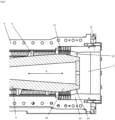
- the worm 6 has a coil-free area 10 .
- a stuffing screw for conveying conveyed material from an overpressure area.
- the inlet area is arranged in the overpressure area or connected to the overpressure area, with the conveyed material being conveyed from the overpressure area to the outlet area of the stuffing screw, forming a plug.
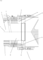
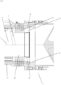
- FIGS. 2 and 3 show an inventive design of the stuffing screw, wherein 2 a first relative positioning of the worm to the coil and 3 Figure 12 shows a second relative positioning of the worm to the spool.
- a worm 6 which can be rotated about an axis of rotation 5 and at least partially has a helix 9 is arranged in a housing 4 .
- the snail 6 has a coil-free area 10 within the coil 8, wherein the Coil 8 and the coil-free worm 10 form an annular area 11 and a calibration area 12 follows the annular area 11 in the conveying direction of the conveyed material.
- the helix-free area of the worm is designed conically with an increasing outer diameter 16, with the imaginary cone tip pointing towards the inlet area and the coil 8 having a constant inner diameter in the conveying direction.
- the calibration area is formed by the area of the coil with a constant inner diameter and by the helix-free area 16 of the worm with an increasing outer diameter, with the coil being adjoined by an area 15 with a diameter that is larger than the constant inner diameter of the coil.
- the sealing effect of the stopper can be increased by narrowing the calibration area 12 or reduced by expanding the calibration area 12 by the axial displacement of the worm 6 .
- Fig.2 shows the stuffing screw 2 with a relative positioning of the screw 6 further in the conveying direction of the conveyed material, ie closer to the outlet area 7.
- Fig.3 the stuffing screw 2 with a relative positioning of the screw 6 against the conveying direction of the conveyed material, ie closer to the inlet area 3.
- the calibration area 12 is in 3 smaller than in 2 , bringing the positioning of the auger 6 in 3 results in a plug with greater sealing effect and the positioning of the auger 6 in 2 leads to a plug with a smaller sealing effect.
- the screw 6 being rotatably arranged in a housing 4 and the screw 6 at least partially having a helix 9 .
- the screw 6 has a coil-free area 10 within the coil 8, with the coil 8 and the coil-free screw 10 forming an annular area 11 and the annular area 11 being followed by a calibration area 12 in the conveying direction of the material to be conveyed.
- the helix-free area 14 of the worm is designed conically with an outer diameter that decreases in the conveying direction, with the imaginary cone tip pointing towards the outlet area 7 , and the coil 8 has an area 13 a decreasing inner diameter.
- Arrow A illustrates the possibility of positioning the worm 6 relative to the coil 8.
- the present invention thus offers numerous advantages: an effective way of controlling the tightness between two process steps and in particular the tightness of an overpressure area, with the overpressure area being charged with a conveyed item or the conveyed item being conveyed out of the overpressure area. This effectively minimizes the risk of steam flowing back or escaping, for example, from the overpressure area. And an optimized drainage performance is possible while at the same time maintaining the tightness in a controllable manner.
- a mode of operation can also be selected in which a required tightness can be set, but which has a minimum power consumption of the stuffing screw. In this way, wear on the stuffing screw, spool, etc.
- the solution according to the invention allows the stuffing screw to be started up quickly with low power consumption, with compliance with the tightness being able to be regulated or set quickly.
Landscapes
- Engineering & Computer Science (AREA)
- Mechanical Engineering (AREA)
- Life Sciences & Earth Sciences (AREA)
- Wood Science & Technology (AREA)
- Screw Conveyors (AREA)
- Sealing Devices (AREA)
Applications Claiming Priority (2)
| Application Number | Priority Date | Filing Date | Title |
|---|---|---|---|
| ATA51014/2019A AT523192B1 (de) | 2019-11-25 | 2019-11-25 | Vorrichtung und verfahren zur abdichtung eines ueberdruckbereichs |
| PCT/EP2020/073174 WO2021104692A1 (de) | 2019-11-25 | 2020-08-19 | Vorrichtung und verfahren zur abdichtung eines ueberdruckbereichs |
Publications (3)
| Publication Number | Publication Date |
|---|---|
| EP4065765A1 EP4065765A1 (de) | 2022-10-05 |
| EP4065765C0 EP4065765C0 (de) | 2023-08-02 |
| EP4065765B1 true EP4065765B1 (de) | 2023-08-02 |
Family
ID=72234817
Family Applications (1)
| Application Number | Title | Priority Date | Filing Date |
|---|---|---|---|
| EP20761174.0A Active EP4065765B1 (de) | 2019-11-25 | 2020-08-19 | Vorrichtung und verfahren zur abdichtung eines überdruckbereichs |
Country Status (5)
| Country | Link |
|---|---|
| EP (1) | EP4065765B1 (pl) |
| CN (2) | CN119663663A (pl) |
| AT (1) | AT523192B1 (pl) |
| PL (1) | PL4065765T3 (pl) |
| WO (1) | WO2021104692A1 (pl) |
Families Citing this family (1)
| Publication number | Priority date | Publication date | Assignee | Title |
|---|---|---|---|---|
| AT527474B1 (de) * | 2024-07-16 | 2025-03-15 | Andritz Ag Maschf | Vorrichtung zur behandlung eines fasermaterials |
Family Cites Families (10)
| Publication number | Priority date | Publication date | Assignee | Title |
|---|---|---|---|---|
| US2428995A (en) * | 1945-05-11 | 1947-10-14 | Rogers John Berrien | Feeding granular materials into a head of pressure |
| DE3545339A1 (de) * | 1985-12-20 | 1987-07-02 | Krupp Koppers Gmbh | Schneckenfoerderer fuer den transport feinzerteilter fester stoffe |
| US5320034A (en) * | 1989-09-19 | 1994-06-14 | Kvaerner Hymac, Inc. | Method and apparatus for increasing surface within wood chips |
| US7300540B2 (en) * | 2004-07-08 | 2007-11-27 | Andritz Inc. | Energy efficient TMP refining of destructured chips |
| CA2507321C (en) * | 2004-07-08 | 2012-06-26 | Andritz Inc. | High intensity refiner plate with inner fiberizing zone |
| DE102008012156A1 (de) * | 2008-03-01 | 2009-09-03 | Karl-Heinz Tetzlaff | Schneckenförderer zur Einspeisung von Biomasse in einen Druckbehälter |
| SE537195C2 (sv) | 2012-02-22 | 2015-03-03 | Valmet Oy | Matningsanordning, system och metod för att hantera icketräbaserat växtmaterial |
| WO2015081443A1 (en) * | 2013-12-05 | 2015-06-11 | Greenfield Specialty Alcohols Inc. | Backpressure control for solid/fluid separation apparatus |
| SE538307C2 (en) * | 2014-09-02 | 2016-05-10 | Valmet Oy | Plug screw feeder, feeder arrangement and system for treatment of lignocellulosic biomass material |
| DE102015002770A1 (de) * | 2015-03-05 | 2016-09-08 | Schenck Process Gmbh | Vorrichtung und Verfahren zur Förderung von Schüttgut in einen Druckraum |
-
2019
- 2019-11-25 AT ATA51014/2019A patent/AT523192B1/de active
-
2020
- 2020-08-19 EP EP20761174.0A patent/EP4065765B1/de active Active
- 2020-08-19 CN CN202510132446.8A patent/CN119663663A/zh active Pending
- 2020-08-19 PL PL20761174.0T patent/PL4065765T3/pl unknown
- 2020-08-19 WO PCT/EP2020/073174 patent/WO2021104692A1/de not_active Ceased
- 2020-08-19 CN CN202080081559.5A patent/CN114787445B/zh active Active
Also Published As
| Publication number | Publication date |
|---|---|
| EP4065765A1 (de) | 2022-10-05 |
| EP4065765C0 (de) | 2023-08-02 |
| CN114787445B (zh) | 2025-02-28 |
| CN114787445A (zh) | 2022-07-22 |
| PL4065765T3 (pl) | 2024-01-29 |
| CN119663663A (zh) | 2025-03-21 |
| AT523192A1 (de) | 2021-06-15 |
| CA3157158A1 (en) | 2021-06-03 |
| WO2021104692A1 (de) | 2021-06-03 |
| AT523192B1 (de) | 2023-04-15 |
Similar Documents
| Publication | Publication Date | Title |
|---|---|---|
| EP1992894B1 (de) | Vorrichtung zum Entwässern von schütt- oder fließfähigem Aufgabegut durch dessen Verdichtung | |
| DE2012645A1 (de) | Vorrichtung zum Extrudieren von schwer extrudierbaren Materialien, insbesondere von Kunststoffabfällen | |
| EP2776551B1 (de) | Einbringschnecke für biogasanlagen | |
| US5000658A (en) | Apparatus for pumping high consistency fiber suspension | |
| WO2009109337A1 (de) | Schneckenförderer zur einspeisung von biomasse in einen druckbehälter | |
| EP4065765B1 (de) | Vorrichtung und verfahren zur abdichtung eines überdruckbereichs | |
| EP2875942A1 (de) | Vorrichtung und Verfahren zum Eindicken von flüssigem feststoffhaltigem Substrat | |
| EP4065763B1 (de) | Vorrichtung und verfahren zur mazeration eines foerderguts | |
| DE10252527B4 (de) | Vorrichtung zur Einbringung von trockenen organischen Stoffen in einen Vergärungsbehälter einer Biogasanlage | |
| EP2792739B1 (de) | Biogasanlage mit einer Fermenter-Beschickungseinrichtung | |
| DE60309683T2 (de) | Zufuhrschleuse | |
| EP0098371B1 (de) | Vorrichtung zum Entwässern und Plastifizieren von Explosivstoffgemischen | |
| EP2139671B1 (de) | Pressschnecke | |
| AT526788B1 (de) | Pyrolyseanlage | |
| EP1130156B1 (de) | Vorrichtung zum Abtrennen von Störstoffen aus faserhaltigem Gut | |
| CA3157158C (en) | Device and method for sealing off an overpressure area | |
| EP2612094B1 (de) | Vorrichtung zum einbringen von abfallstoffen und/oder alternativen brennstoffen in den innenraum eines aggregats | |
| RU2821883C1 (ru) | Шнек избыточной подачи и способ транспортировки транспортируемого материала с использованием такого шнека | |
| EP3320976B1 (de) | Einlaufvorrichtung für eine dekanterzentrifuge | |
| EP4448155B1 (de) | Paddelmischvorrichtung und verfahren zu ihrer reinigung | |
| DE202015105904U1 (de) | Pumpenseparator zum Abscheiden von Flüssigkeitsbestandteilen aus einem Flüssigkeit-Feststoff-Gemisch | |
| DE20101992U1 (de) | Vorrichtung zur Dispergierung eines Papierfaserstoffes | |
| DE10105281A1 (de) | Vorrichtung zur Dispergierung eines Papierfaserstoffes | |
| EP4631356A1 (de) | Vorrichtung und verfahren zum herstellen von pflanzlicher milch | |
| DE4313888A1 (de) | Reaktor zur Zerlegung von Altpapier |
Legal Events
| Date | Code | Title | Description |
|---|---|---|---|
| STAA | Information on the status of an ep patent application or granted ep patent |
Free format text: STATUS: UNKNOWN |
|
| STAA | Information on the status of an ep patent application or granted ep patent |
Free format text: STATUS: THE INTERNATIONAL PUBLICATION HAS BEEN MADE |
|
| PUAI | Public reference made under article 153(3) epc to a published international application that has entered the european phase |
Free format text: ORIGINAL CODE: 0009012 |
|
| STAA | Information on the status of an ep patent application or granted ep patent |
Free format text: STATUS: REQUEST FOR EXAMINATION WAS MADE |
|
| 17P | Request for examination filed |
Effective date: 20220325 |
|
| AK | Designated contracting states |
Kind code of ref document: A1 Designated state(s): AL AT BE BG CH CY CZ DE DK EE ES FI FR GB GR HR HU IE IS IT LI LT LU LV MC MK MT NL NO PL PT RO RS SE SI SK SM TR |
|
| DAV | Request for validation of the european patent (deleted) | ||
| DAX | Request for extension of the european patent (deleted) | ||
| GRAP | Despatch of communication of intention to grant a patent |
Free format text: ORIGINAL CODE: EPIDOSNIGR1 |
|
| STAA | Information on the status of an ep patent application or granted ep patent |
Free format text: STATUS: GRANT OF PATENT IS INTENDED |
|
| INTG | Intention to grant announced |
Effective date: 20230316 |
|
| GRAS | Grant fee paid |
Free format text: ORIGINAL CODE: EPIDOSNIGR3 |
|
| GRAA | (expected) grant |
Free format text: ORIGINAL CODE: 0009210 |
|
| STAA | Information on the status of an ep patent application or granted ep patent |
Free format text: STATUS: THE PATENT HAS BEEN GRANTED |
|
| AK | Designated contracting states |
Kind code of ref document: B1 Designated state(s): AL AT BE BG CH CY CZ DE DK EE ES FI FR GB GR HR HU IE IS IT LI LT LU LV MC MK MT NL NO PL PT RO RS SE SI SK SM TR |
|
| REG | Reference to a national code |
Ref country code: GB Ref legal event code: FG4D Free format text: NOT ENGLISH |
|
| REG | Reference to a national code |
Ref country code: CH Ref legal event code: EP |
|
| REG | Reference to a national code |
Ref country code: DE Ref legal event code: R096 Ref document number: 502020004537 Country of ref document: DE |
|
| REG | Reference to a national code |
Ref country code: IE Ref legal event code: FG4D Free format text: LANGUAGE OF EP DOCUMENT: GERMAN |
|
| U01 | Request for unitary effect filed |
Effective date: 20230807 |
|
| U07 | Unitary effect registered |
Designated state(s): AT BE BG DE DK EE FI FR IT LT LU LV MT NL PT SE SI Effective date: 20230821 |
|
| U20 | Renewal fee for the european patent with unitary effect paid |
Year of fee payment: 4 Effective date: 20230914 |
|
| PG25 | Lapsed in a contracting state [announced via postgrant information from national office to epo] |
Ref country code: GR Free format text: LAPSE BECAUSE OF FAILURE TO SUBMIT A TRANSLATION OF THE DESCRIPTION OR TO PAY THE FEE WITHIN THE PRESCRIBED TIME-LIMIT Effective date: 20231103 |
|
| PG25 | Lapsed in a contracting state [announced via postgrant information from national office to epo] |
Ref country code: IS Free format text: LAPSE BECAUSE OF FAILURE TO SUBMIT A TRANSLATION OF THE DESCRIPTION OR TO PAY THE FEE WITHIN THE PRESCRIBED TIME-LIMIT Effective date: 20231202 |
|
| PG25 | Lapsed in a contracting state [announced via postgrant information from national office to epo] |
Ref country code: RS Free format text: LAPSE BECAUSE OF FAILURE TO SUBMIT A TRANSLATION OF THE DESCRIPTION OR TO PAY THE FEE WITHIN THE PRESCRIBED TIME-LIMIT Effective date: 20230802 Ref country code: NO Free format text: LAPSE BECAUSE OF FAILURE TO SUBMIT A TRANSLATION OF THE DESCRIPTION OR TO PAY THE FEE WITHIN THE PRESCRIBED TIME-LIMIT Effective date: 20231102 Ref country code: IS Free format text: LAPSE BECAUSE OF FAILURE TO SUBMIT A TRANSLATION OF THE DESCRIPTION OR TO PAY THE FEE WITHIN THE PRESCRIBED TIME-LIMIT Effective date: 20231202 Ref country code: HR Free format text: LAPSE BECAUSE OF FAILURE TO SUBMIT A TRANSLATION OF THE DESCRIPTION OR TO PAY THE FEE WITHIN THE PRESCRIBED TIME-LIMIT Effective date: 20230802 Ref country code: GR Free format text: LAPSE BECAUSE OF FAILURE TO SUBMIT A TRANSLATION OF THE DESCRIPTION OR TO PAY THE FEE WITHIN THE PRESCRIBED TIME-LIMIT Effective date: 20231103 |
|
| REG | Reference to a national code |
Ref country code: CH Ref legal event code: PL |
|
| PG25 | Lapsed in a contracting state [announced via postgrant information from national office to epo] |
Ref country code: ES Free format text: LAPSE BECAUSE OF FAILURE TO SUBMIT A TRANSLATION OF THE DESCRIPTION OR TO PAY THE FEE WITHIN THE PRESCRIBED TIME-LIMIT Effective date: 20230802 |
|
| PG25 | Lapsed in a contracting state [announced via postgrant information from national office to epo] |
Ref country code: SM Free format text: LAPSE BECAUSE OF FAILURE TO SUBMIT A TRANSLATION OF THE DESCRIPTION OR TO PAY THE FEE WITHIN THE PRESCRIBED TIME-LIMIT Effective date: 20230802 Ref country code: RO Free format text: LAPSE BECAUSE OF FAILURE TO SUBMIT A TRANSLATION OF THE DESCRIPTION OR TO PAY THE FEE WITHIN THE PRESCRIBED TIME-LIMIT Effective date: 20230802 Ref country code: ES Free format text: LAPSE BECAUSE OF FAILURE TO SUBMIT A TRANSLATION OF THE DESCRIPTION OR TO PAY THE FEE WITHIN THE PRESCRIBED TIME-LIMIT Effective date: 20230802 Ref country code: CZ Free format text: LAPSE BECAUSE OF FAILURE TO SUBMIT A TRANSLATION OF THE DESCRIPTION OR TO PAY THE FEE WITHIN THE PRESCRIBED TIME-LIMIT Effective date: 20230802 Ref country code: SK Free format text: LAPSE BECAUSE OF FAILURE TO SUBMIT A TRANSLATION OF THE DESCRIPTION OR TO PAY THE FEE WITHIN THE PRESCRIBED TIME-LIMIT Effective date: 20230802 Ref country code: CH Free format text: LAPSE BECAUSE OF NON-PAYMENT OF DUE FEES Effective date: 20230831 |
|
| REG | Reference to a national code |
Ref country code: DE Ref legal event code: R097 Ref document number: 502020004537 Country of ref document: DE |
|
| REG | Reference to a national code |
Ref country code: IE Ref legal event code: MM4A |
|
| PG25 | Lapsed in a contracting state [announced via postgrant information from national office to epo] |
Ref country code: MC Free format text: LAPSE BECAUSE OF FAILURE TO SUBMIT A TRANSLATION OF THE DESCRIPTION OR TO PAY THE FEE WITHIN THE PRESCRIBED TIME-LIMIT Effective date: 20230802 |
|
| PLBE | No opposition filed within time limit |
Free format text: ORIGINAL CODE: 0009261 |
|
| STAA | Information on the status of an ep patent application or granted ep patent |
Free format text: STATUS: NO OPPOSITION FILED WITHIN TIME LIMIT |
|
| PG25 | Lapsed in a contracting state [announced via postgrant information from national office to epo] |
Ref country code: IE Free format text: LAPSE BECAUSE OF NON-PAYMENT OF DUE FEES Effective date: 20230819 |
|
| 26N | No opposition filed |
Effective date: 20240503 |
|
| PG25 | Lapsed in a contracting state [announced via postgrant information from national office to epo] |
Ref country code: IE Free format text: LAPSE BECAUSE OF NON-PAYMENT OF DUE FEES Effective date: 20230819 |
|
| U20 | Renewal fee for the european patent with unitary effect paid |
Year of fee payment: 5 Effective date: 20240827 |
|
| GBPC | Gb: european patent ceased through non-payment of renewal fee |
Effective date: 20240819 |
|
| PG25 | Lapsed in a contracting state [announced via postgrant information from national office to epo] |
Ref country code: GB Free format text: LAPSE BECAUSE OF NON-PAYMENT OF DUE FEES Effective date: 20240819 |
|
| PG25 | Lapsed in a contracting state [announced via postgrant information from national office to epo] |
Ref country code: CY Free format text: LAPSE BECAUSE OF FAILURE TO SUBMIT A TRANSLATION OF THE DESCRIPTION OR TO PAY THE FEE WITHIN THE PRESCRIBED TIME-LIMIT; INVALID AB INITIO Effective date: 20200819 |
|
| PG25 | Lapsed in a contracting state [announced via postgrant information from national office to epo] |
Ref country code: HU Free format text: LAPSE BECAUSE OF FAILURE TO SUBMIT A TRANSLATION OF THE DESCRIPTION OR TO PAY THE FEE WITHIN THE PRESCRIBED TIME-LIMIT; INVALID AB INITIO Effective date: 20200819 |
|
| U20 | Renewal fee for the european patent with unitary effect paid |
Year of fee payment: 6 Effective date: 20250827 |
|
| PGFP | Annual fee paid to national office [announced via postgrant information from national office to epo] |
Ref country code: TR Payment date: 20250812 Year of fee payment: 6 Ref country code: PL Payment date: 20250811 Year of fee payment: 6 |