EP4065286B1 - Verfahren zur beurteilung einer form eines glockenförmigen flüssigkeitssprays - Google Patents
Verfahren zur beurteilung einer form eines glockenförmigen flüssigkeitssprays Download PDFInfo
- Publication number
- EP4065286B1 EP4065286B1 EP20807796.6A EP20807796A EP4065286B1 EP 4065286 B1 EP4065286 B1 EP 4065286B1 EP 20807796 A EP20807796 A EP 20807796A EP 4065286 B1 EP4065286 B1 EP 4065286B1
- Authority
- EP
- European Patent Office
- Prior art keywords
- filament
- shape parameter
- bell
- shape
- spray
- Prior art date
- Legal status (The legal status is an assumption and is not a legal conclusion. Google has not performed a legal analysis and makes no representation as to the accuracy of the status listed.)
- Active
Links
Images

Classifications
-
- B—PERFORMING OPERATIONS; TRANSPORTING
- B05—SPRAYING OR ATOMISING IN GENERAL; APPLYING FLUENT MATERIALS TO SURFACES, IN GENERAL
- B05B—SPRAYING APPARATUS; ATOMISING APPARATUS; NOZZLES
- B05B3/00—Spraying or sprinkling apparatus with moving outlet elements or moving deflecting elements
- B05B3/02—Spraying or sprinkling apparatus with moving outlet elements or moving deflecting elements with rotating elements
- B05B3/10—Spraying or sprinkling apparatus with moving outlet elements or moving deflecting elements with rotating elements discharging over substantially the whole periphery of the rotating member
- B05B3/1007—Spraying or sprinkling apparatus with moving outlet elements or moving deflecting elements with rotating elements discharging over substantially the whole periphery of the rotating member characterised by the rotating member
- B05B3/1014—Spraying or sprinkling apparatus with moving outlet elements or moving deflecting elements with rotating elements discharging over substantially the whole periphery of the rotating member characterised by the rotating member with a spraying edge, e.g. like a cup or a bell
-
- B—PERFORMING OPERATIONS; TRANSPORTING
- B05—SPRAYING OR ATOMISING IN GENERAL; APPLYING FLUENT MATERIALS TO SURFACES, IN GENERAL
- B05B—SPRAYING APPARATUS; ATOMISING APPARATUS; NOZZLES
- B05B12/00—Arrangements for controlling delivery; Arrangements for controlling the spray area
- B05B12/08—Arrangements for controlling delivery; Arrangements for controlling the spray area responsive to condition of liquid or other fluent material to be discharged, of ambient medium or of target ; responsive to condition of spray devices or of supply means, e.g. pipes, pumps or their drive means
- B05B12/082—Arrangements for controlling delivery; Arrangements for controlling the spray area responsive to condition of liquid or other fluent material to be discharged, of ambient medium or of target ; responsive to condition of spray devices or of supply means, e.g. pipes, pumps or their drive means responsive to a condition of the discharged jet or spray, e.g. to jet shape, spray pattern or droplet size
-
- B—PERFORMING OPERATIONS; TRANSPORTING
- B05—SPRAYING OR ATOMISING IN GENERAL; APPLYING FLUENT MATERIALS TO SURFACES, IN GENERAL
- B05B—SPRAYING APPARATUS; ATOMISING APPARATUS; NOZZLES
- B05B5/00—Electrostatic spraying apparatus; Spraying apparatus with means for charging the spray electrically; Apparatus for spraying liquids or other fluent materials by other electric means
- B05B5/025—Discharge apparatus, e.g. electrostatic spray guns
- B05B5/04—Discharge apparatus, e.g. electrostatic spray guns characterised by having rotary outlet or deflecting elements, i.e. spraying being also effected by centrifugal forces
- B05B5/0403—Discharge apparatus, e.g. electrostatic spray guns characterised by having rotary outlet or deflecting elements, i.e. spraying being also effected by centrifugal forces characterised by the rotating member
- B05B5/0407—Discharge apparatus, e.g. electrostatic spray guns characterised by having rotary outlet or deflecting elements, i.e. spraying being also effected by centrifugal forces characterised by the rotating member with a spraying edge, e.g. like a cup or a bell
Definitions
- the invention relates to a method for assessing a shape of a bell-shaped liquid spray.
- the method comprises the steps of operating a spray nozzle for delivering a bell-shaped liquid spray and capturing an image of a plurality of liquid jets forming the delivered bell-shaped liquid spray during operation of the spray nozzle.
- the invention further relates to a computer program product for assessing a shape of a bell-shaped liquid spray.
- Combustion engines usually generate an angular momentum by combusting an injected fuel spray.
- JP H03 186768 A discloses a method for assessing a shape of an injected fuel as a liquid spray.
- the liquid spray comprises two liquid spray beams extending from a spray nozzle with a relative acute angle greater than zero.
- a camera captures a lateral image of the liquid spray, and an image processor graphically derives a linear beam direction for each liquid spray beam from the captured image and approximates the relative acute angle of the two liquid spray beams to be the relative angle of the derived two linear beam directions.
- JP H03 253762 A discloses also discloses a method for assessing a shape of an injected fuel as a liquid spray by means of a camera capturing images of the liquid spray and processing the captured images. A quality of the liquid spray is assessed by graphically deriving edges of the liquid spray from the captured images and calculating angles between derived opposite edges.
- JP 2001 050866 A discloses another method for assessing a shape of an injected fuel as a liquid spray.
- the shape and a density distribution of the liquid spray are assessed by processing an image of the liquid spray reflecting and absorbing a light emitted by the light source.
- the shape and the density distribution of the liquid spray is calculated from a brightness distribution of the image.
- Bell-shaped liquid sprays are widely used for applying liquid coatings onto surfaces.
- a bell-shaped liquid spray may be delivered by a disc-shaped or conical spray nozzle rotating about a rotation axis at a high angular speed while the liquid coating is continuously fed to the spray nozzle.
- the fast rotation of the spray nozzle makes the liquid coating undergo a strong centrifugal force which accelerates the liquid coating in a radial direction with respect to the rotation axis. Apart from the centrifugal force, the liquid coating undergoes a plurality of further forces like a viscoelastic force, a surface tension force, a gravitational force, an aerodynamic drag force and an electrostatic force.
- the accelerated liquid coating forms a plurality of distinct liquid jets when separating from the spray nozzle.
- the liquid jets are arranged along the perimeter of the spray nozzle at essentially equal distances from one another. The interplay of the above-mentioned forces cooperation leads to a bell-shape of the liquid coating spray.
- a bell-shaped liquid coating spray may be used for coating a large variety of different workpieces and is preferably used by car manufacturers for applying coatings onto surfaces of car body parts.
- Car body parts are coated mainly for an aesthetic appearance of the car and for protecting the materials of the car body parts from deterioration, i.e. from damage, wear and corrosion.
- a coating has to be applied onto a surface of a car body part as uniformly as possible.
- One aspect of the invention is a method for assessing a shape of a bell-shaped liquid spray.
- the method comprises the steps of operating a spray nozzle for delivering a bell-shaped liquid spray and capturing an image of a plurality of liquid jets forming the delivered bell-shaped liquid spray during operation of the spray nozzle.
- the method is based on a normal operation of the spray nozzle.
- the spray nozzle rotates at an angular speed in a range about from 10.000 rotations per minute (rpm) to 70.000 rpm about a rotation axis.
- the spray nozzle is rotating the liquid, peferably a coating, is continuously fed to the spray nozzle at a feeding rate in a range about from 50 ml/min to 400 ml/min. Due to an interplay of a centrifugal force caused by rotation of the spray nozzle and one or more of a viscoelastic force, a surface tension force, a gravitational force, an aerodynamic drag force and an electrostatic force the liquid spray has a shape of a bell while being delivered by the spray nozzle.
- the angular speed of the spray nozzle and the feeding rate of the liquid are two important parameters affecting the shape of the bell-shaped liquid spray.
- a third important parameter affecting the shape of the bell-shaped liquid spray is a viscosity of the liquid and a dependency of the viscosity from an external force applied to the liquid. With respect to the dependency of the viscosity from an external force, Newtonian liquids and non-Newtonian liquids may be distinguished.
- the former liquids have a viscosity being independent of any external force, i.e. being constant with respect to external forces, while the latter liquids have a viscosity varying dependent on the external force.
- a high-speed camera captures one or more subsequent images of the bell-shaped liquid spray being delivered by the spray nozzle.
- Each captured image represents a frozen state of the bell-shaped liquid spray and comprises a plurality of liquid jets forming the bell-shaped liquid spray which are arranged next to each other along a perimeter of the spray nozzle.
- the method comprises the further steps of processing the captured image and deriving at least one shape parameter of the liquid jets from the processed image.
- the inventive method is an empirical method which is directed to obtaining one or more shape parameters associated with the real bell-shaped liquid spray delivered by the real spray nozzle with a real liquid being fed thereto.
- the at least one shape parameter is derived by means of image processing.
- Image processing may comprise one or more steps of pre-processing, segmenting, extracting and post-processing which are described in more detail below.
- a lateral view image and/or a partial image of the spray nozzle and the plurality of liquid jets is captured.
- the lateral view image is captured when the high-speed camera is arranged such that an optical axis of the camera extends transverse or particularly perpendicular to an outer lateral surface of the bell-shaped liquid spray. Capturing a partial image is sufficient and facilitates both arranging the high-speed camera relative to the spray nozzle and processing of the captured image.
- processing the captured image comprises converting the captured image to a binary image, the binary image comprising a plurality of filaments each filament corresponding to a liquid jet and a plurality of arcs each arc connecting two filaments being located next to each other.
- the binary image may comprise a monochrome, i.e. single-colored, background which, for instance, may be black or white and a foreground which, in turn, may have one or more colors each color of the foreground being different from the single color of the background.
- the binary image facilitates distinguishing the foreground from the background and, particularly, completely ignoring the background of the binary image.
- the foreground may comprise the filaments and the arcs which alternate along the perimeter of the spray nozzle.
- a filament shall be understood to be a thin line.
- deriving the at least one shape parameter comprises calculating a distance between a determined first point of a first arc and a determined second point of a second arc, the first arc and the second arc being located on opposite sides of a filament and connected to the filament, and using the calculated distance as the at least one shape parameter, the at least one shape parameter indicating a diameter of the corresponding liquid jet.
- the distance may be calculated by counting a number of pixels between the first point and the second point and then transforming the counted number of pixels to a distance by using a resolution of the binary image.
- the distance between the first point and the second point may be interpreted as a diameter or a thickness of the liquid jet corresponding to the filament. The larger the distance between the first and second points is the more liquid has the liquid jet, i.e. the thicker the liquid jet is.
- determining the first point and the second point comprises both minimizing the calculated distance between the first point and the second point and, at the same time, maximizing a distance of the first point and the second point from the filament, repectively.
- the first point, the second point and a nearest point of the filament form a triangle.
- the first and the second point may be easily determined by pattern recognition.
- determining the at least one shape parameter may comprise selecting a segment of the binary image, the selected segment essentially comprising the arcs only. Recognizing the arcs in the selected segment automatically, i.e. by pattern recognition, is facilitated.
- deriving the at least one shape parameter comprises isolating a filament, calculating a length of the isolated filament and using the calculated length as the at least one shape parameter, the at least one shape parameter indicating a length of the liquid jet and/or calculating a plurality of widths of the isolated filament along a longitudinal extension of the isolated filament and using the plurality of calculated widths as the at least one shape parameter, the at least one shape parameter indicating a longitudinal evolution of the width of the corresponding liquid jet.
- the length of the isolated filament may be calculated by counting a number of pixels between a first end point of the filament and a second end point of the filament and then transforming the counted number of pixels to a length by using a resolution of the binary image.
- the width of the isolated filament at a longitudinal position of the isolated filament may be calculated by counting a number of pixels of the filament crosswise to the longitudinal direction of the isolated filament and then transforming the counted number of pixels to a width by using a resolution of the binary image.
- isolating the filament may comprise removing the plurality of arcs from the binary image. Removing the arcs removes connections between the filaments separating the filaments from each other, i.e. rendering the filaments separate objects. With isolated filaments recognizing the filaments automatically, i.e. by pattern recognition, is facilitated.
- processing the captured image may comprise extracting a filament from the binary image and using the shape of the filament as the at least one shape parameter, the at least one shape parameter indicating a trajectory of the corresponding liquid jet.
- the filament may be extracted by means of pattern recognition.
- the filament is used as a whole to represent the trajectory of the corresponding liquid jet.
- the trajectory comprises a length and a possibly varying curvature.
- a sequence of images is captured over a period of time and deriving the at least one shape parameter comprises calculating a whipping frequence of an aligned filament of the corresponding binary images by applying a fast Fourier transformation to the aligned filament and using the calculated whipping frequency as the at least one shape parameter, the at least one shape parameter indicating a whipping frequence of the corresponding liquid jet.
- the whipping frequence is a dynamic shape parameter as it reflects a whipping movement of the corresponding liquid jet, i.e. a periodic variation of the liquid jet trajectories, during operation of the spray nozzle.
- aligning the filament comprises arranging an extracted filament in a cartesian coordinate system and/or correcting an angle of an extracted filament with respect to a shape of the spray nozzle.
- the cartesian coordinate system comprising the extracted filament allows for an advanced calculation of shape parameters.
- the filaments are distributed along the perimeter of the spray nozzle, the filaments are rotated relative to each other by a respective associated polar angle with respect to the rotation axis. Correcting the angle of the aligned filament by the associated polar angle pretends the spray nozzle to have a straight perimeter instead of a circular perimeter. Correcting the angle improves an alignment of the filament and increases an accuracy of the shape parameter to be derived.
- deriving the at least one shape parameter comprises removing an intersecting filament from the binary image. Intersecting filaments join or cross each other. Removing an intersecting filament or preferably every intersecting filament from the binary image may facilitate recognizing a filament automatically, i.e. by pattern recognition, and increases an accuracy of the shape parameter to be derived.
- any deriving of a shape parameter according to the proposed method may comprise averaging over a large number of liquid jets, i.e. filaments corresponding to liquid jets and connecting arcs, in order to increase an accuracy of the respective derived shape parameter.
- the derived at least one shape parameter may be used as an input for numerically simulating a bell-shaped liquid spray and/or as a verification means for a numerically simulated bell-shaped liquid spray.
- the derived shape parameter may either be used to increase the accuracy of a numerical simulation of the bell-shaped liquid spray or to verify the accuracy of a numeric simulation of the bell-shaped liquid spray.
- the at least one shape parameter may be used for assessing a dependence of the derived at least one shape parameter from a rotational speed of the spray nozzle or from a feeding rate of the liquid or from an airflow. Taking into account any dependency of the shape parameter on parameters of the bell-shaped liquid spray configuration further improves the accuracy of the numeric simulation and the predictive power thereof.
- the method may be carried out by a processor executing a program code implementing the method. In this way assessing the bell-shaped liquid spray may be automated at least partially which increases an efficiency and accuracy of the assessing process.
- the computer program product comprises a data carrier storing a program code to be executed by a processor.
- the data carrier may be used for installing the stored program code and/or for upgrading an installed program code with the stored program code.
- the program code implements an inventive method.
- the stored program code enables an existing bell-shaped liquid spray assessment configuration for an increased efficiency and accuracy.
- the bell-shaped liquid spray assessment configuration comprises a bell-shaped liquid spray configuration, a high-speed camera and a computer being connected to the camera and having a processor and an image processing software to be executed by the processor for processing images captured by the high-speed camera.
- shape parameters affecting the bell-shaped liquid spray and dependencies of the shape parameters on parameters of the bell-shaped liquid spray configuration may be empirically derived with both a high efficiency and a high accuracy.
- the derived empirical shape parameters may be used for improving or verifying a numeric simulation of the bell-shaped liquid spray.
- the improved numeric simulation exemplarily allows for optimizing the parameters of the bell-shaped liquid spray configuration in order to achieve a higher quality of a coating applied onto a surface by bell-shaped liquid spray.
- Another advantage of the inventive method is that the inventive method may readily be based on an existing bell-shaped liquid spray assessment configuration.
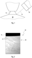
- Fig. 1 shows a schematic illustration of a lateral view of a bell-shaped liquid spray assessment configuration according to the invention.
- the bell-shaped liquid spray assessment configuration comprises a liquid spray configuration with a conical spray nozzle 10 for delivering a bell-shaped liquid spray 30.
- the bell-shaped liquid spray configuration may be used, for instance, by a car manufacturer for applying a liquid coating onto a surface of a car body part (not shown).
- the bell-shaped liquid spray assessment configuration comprises a high-speed camera 20.
- the high-speed camera 20 is arranged such that an optical axis 21 of the high-speed camera extends transverse to an outer lateral surface of the bell-shaped liquid spray 30.
- the bell-shaped liquid spray assessment configuration may be used to assess a shape of the bell-shaped liquid spray 30.
- the bell-shaped liquid spray assessment configuration further comprises a computer (not shown).
- the computer has a processor and a memory comprising a program code, the program code implementing a method for assessing a shape of a bell-shaped liquid spray 30 and being executable by the processor.
- the program code may have been installed in the memory of the computer from a computer program product for assessing a shape of a bell-shaped liquid spray 30 according to the invention, the computer program product comprising a data carrier like a DVD or an USB stick storing the program code.
- the computer is connected to the high-speed camera 20 for receiving one or more captured images 40 (see fig. 2 ) from the high-speed camera 20.
- the bell-shaped liquid spray assessment configuration is configured for carrying out a method for assessing a shape of the bell-shaped liquid spray 30 according to the invention.
- the method comprises the following steps.
- the bell-shaped liquid spray 30 is delivered by the spray nozzle 10 during a normal operation of the bell-shaped liquid spray configuration.
- the spray nozzle 10 rotates at an angular speed in a range about from 10.000 rotations per minute (rpm) to 30.000 rpm about a rotation axis.
- the spray nozzle 10 is rotating a liquid, peferably a coating, is continuously fed to the spray nozzle 10 at a feeding rate in a range about from 50 ml/min to 200 ml/min.
- the high-speed camera 20 captures an image 40 (see fig. 2 ) of the delivered bell-shaped liquid spray 30.
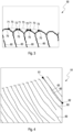
- Fig. 2 shows an exemplary image 40 captured by the high-speed camera 20 of the bell-shaped liquid spray assessment configuration shown in fig. 1 .
- the captured image 40 is a partial lateral view of the spray nozzle 10 and the bell-shaped liquid spray 30.
- the captured image 40 comprises a plurality of liquid jets 31 forming the delivered bell-shaped liquid spray 30.
- the captured image 40 is processed by the computer and at least one shape parameter of the liquid jets 31 is derived from the processed image.
- Processing the captured image 40 comprises converting the captured image 40 to a binary image 50 (see fig. 3 ), 51 (see fig. 4 ).
- the processing may comprise a pre-processing of the captured image 40 like applying one or more graphic filter algorithms to the captured image 40 in order to increase a contrast of the captured image 40 or to sharpen the captured image 40.
- the processing may also comprise a post-processing of the binary image 50 like thickening and/or coloring the filaments 60 and/or arcs 70 in order to facilitate an automatic pattern recognition.
- Fig. 3 shows a first binary image 50 the captured image 40 shown in fig. 2 has been converted to.
- the binary image 50 comprises a plurality of filaments 60. Each filament 60 corresponds to a liquid jet 31.
- the binary image 50 further comprises a plurality of arcs 70. Each arc 70 connects two filaments 60 being located next to each other.
- a diameter of a liquid jet 31 may be derived from the first binary image 50.
- Deriving the first shape parameter comprises calculating a distance 73 between a determined first point 71 of a first arc 70 and a determined second point 72 of a second arc 70, the first arc 70 and the second arc 70 being located on opposite sides of a filament 60 corresponding to the liquid jet 31 connected to the filament 60.
- Determining the first point 71 and the second point 72 comprises both minimizing the calculated distance 73 between the first point 71 and the second point 72 and, at the same time, maximizing a distance of the first point 71 and the second point 72 from the filament 60, repectively.
- the distance 73 may be calculated by counting a number of pixels between the first point 71 and the second point 72 and then transforming the counted number of pixels to a distance 73 by using a resolution of the binary image.
- the calculated distance 73 is used as the first shape parameter indicating a diameter of the corresponding liquid jet 31.
- Deriving the first shape parameter may further comprise averaging the calculated distance 73 over a large number filaments 60 and connecting arcs 70 in order to increase an accuracy of the first shape parameter.
- Fig. 4 shows a second binary image 51 the captured image 40 shown in fig. 2 has been converted to.
- the second binary image 51 comprises a plurality of filaments 60. Each filament 60 corresponds to a liquid jet 31.
- a length of a liquid jet 31 may be derived from the second binary image 51.
- Deriving the second parameter comprises removing intersecting filaments from the binary image 50 and isolating a filament 60 corresponding to the liquid jet 31, calculating a length 63 of the isolated filament 60.
- Isolating the filament 60 comprises removing the plurality of arcs 70 from the binary image 51.
- the length of the isolated filament 60 may be calculated by counting a number of pixels between a first end point 61 of the filament 60 and a second end point 62 of the filament 60 and then transforming the counted number of pixels to a length by using a resolution of the binary image 51.
- the calculated length 63 is used as the second shape parameter indicating a length of the corresponding liquid jet 31.
- Deriving the second shape parameter may further comprise averaging the calculated length 63 over a large number filaments 60 in order to increase an accuracy of the second shape parameter.
- a longitudinal evolution of the width of the corresponding liquid jet 31 may be derived from the second binary image 51. Deriving the third shape parameter comprises calculating a plurality of widths of the isolated filament 60 at a plurality of longitudinal positions along a longitudinal extension of the isolated filament 60.
- the width of the isolated filament 60 at a longitudinal position of the isolated filament 60 may be calculated by counting a number of pixels of the isolated filament 60 crosswise to a longitudinal direction of the isolated filament 60 and then transforming the counted number of pixels to a width by using a resolution of the second binary image 51.
- the plurality of widths is used as the third shape parameter.
- Deriving the third shape parameter may further comprise averaging the calculated longitudinal evolutions of width over a large number filaments 60 in order to increase an accuracy of the third shape parameter.
- a trajectory of a liquid jet 31 may be derived from the second binary image 51.
- Deriving the fourth shape parameter comprises removing intersecting filaments from the binary image 50 and extracting a filament 60 corresponding to the liquid jet 31 from the binary image 50 and may comprise correcting an angle of the extracted filament 60 with respect to a shape of the spray nozzle 10.
- the shape of the filament 60 is used as the fourth shape parameter indicating a trajectory of the corresponding liquid jet 31.
- Deriving the fourth shape parameter may further comprise averaging the shape over a large number filaments 60 in order to increase an accuracy of the fourth shape parameter.
- Fig. 5 shows a coordinate system comprising a plurality of aligned filaments 60.
- a fifth parameter whipping frequency of a liquid jet 31 is derived from the cartesion coordinate system 80.
- Deriving the fifth parameter is based on a sequence of images 40 being captured over a period of time and comprises calculating a whipping frequency of an aligned filament 60 corresponding to the liquid jet 31 of the corresponding binary images 50 by applying a fast Fourier transformation to the aligned filament 60.
- Aligning the filament 60 comprises removing intersecting filaments from the binary image 50, extracting a filament 60 corresponding to the liquid jet 31 from the binary image 50 and arranging the extracted filament 60 in the cartesian coordinate system 80 and may comprise correcting an angle of the extracted filament 60 with respect to a shape of the spray nozzle 10.
- the calculated whipping frequency is used as the fifth shape parameter indicating a whipping frequency of the corresponding liquid jet 31.
- Deriving the fifth shape parameter may further comprise averaging the calculated whipping frequency over a large number filaments 60 per image 40 in order to increase an accuracy of the fifth shape parameter.
- Fig. 6 shows a schematic illustration of a top view of a numerically simulated bell-shaped liquid spray 90 according to the invention.
- the derived shape parameters are used as an input for numerically simulating a bell-shaped liquid spray 90 or as a verification means for a numerically simulated bell-shaped liquid spray 90, the bell-shaped liquid spray 90 having a plurality of numerically simulated liquid jets 91.
- the derived at least one shape parameter may be used for assessing a dependence of the at least one shape parameter on a rotational speed of the spray nozzle 10 or on a feeding rate of the liquid or from an airflow.
Landscapes
- Length Measuring Devices By Optical Means (AREA)
- Spray Control Apparatus (AREA)
- Testing Of Devices, Machine Parts, Or Other Structures Thereof (AREA)
- Application Of Or Painting With Fluid Materials (AREA)
- Nozzles (AREA)
- Indicating Or Recording The Presence, Absence, Or Direction Of Movement (AREA)
Claims (14)
- Verfahren zur Beurteilung einer Form eines glockenförmigen Flüssigkeitsprays (30), das die folgenden Schritte umfasst:° Betreiben einer Sprühdüse (10) zur Abgabe eines glockenförmigen Flüssigkeitsprays (30);° Erfassen eines Bilds von mehreren Flüssigkeitsstrahlen (31), die das abgegebene glockenförmige Flüssigkeitsspray (30) bilden, während des Betriebs der Sprühdüse (10);° Verarbeiten des erfassten Bilds (40), wobei das Verarbeiten des erfassten Bilds (40) Umwandeln des erfassten Bilds (40) in ein binäres Bild (50, 51) umfasst, wobei das binäre Bild (50, 51) mehrere Filamente (60), wobei jedes Filament (60) einem Flüssigkeitsstrahl (31) entspricht, und mehrere Bögen (70), wobei jeder Bogen (70) zwei nebeneinanderliegende Filamente (60) verbindet, umfasst; und∘ Ableiten mindestens eines Formparameters des Flüssigkeitsstrahls (31) aus dem verarbeiteten Bild.
- Verfahren nach Anspruch 1, wobei ein Seitenansichtsbild und/oder ein Teilbild der Sprühdüse (10) und der mehreren Flüssigkeitsstrahlen (31) erfasst wird.
- Verfahren nach einem der Ansprüche 1 oder 2, wobei das Ableiten des mindestens einen Formparameters Berechnen eines Abstands (73) zwischen einem bestimmten ersten Punkt (71) eines ersten Bogens (70) und einem bestimmten zweiten Punkt (72) eines zweiten Bogens (70), wobei sich der erste Bogen (70) und der zweite Bogen (70) auf gegenüberliegenden Seiten eines Filaments (60) befinden und mit dem Filament (60) verbunden sind, und Verwenden des berechneten Abstands (73) als den mindestens einen Formparameter, wobei der mindestens eine Formparameter einen Durchmesser des entsprechenden Flüssigkeitsstrahls (31) angibt, umfasst.
- Verfahren nach Anspruch 3, wobei das Bestimmen des ersten Punkts (71) und des zweiten Punkts (72) sowohl Minimieren des berechneten Abstands (73) zwischen dem ersten Punkt (71) und dem zweiten Punkt (72) als auch gleichzeitig Maximieren eines Abstands des ersten Punkts (71) bzw. des zweiten Punkts (72) von dem Filament (60) umfasst.
- Verfahren nach einem der Ansprüche 1 bis 4, wobei das Ableiten des mindestens einen Formparameters Isolieren eines Filaments (60), Berechnen einer Länge (63) des isolierten Filaments (60) und Verwenden der berechneten Länge (63) als den mindestens einen Formparameter, wobei der mindestens eine Formparameter eine Länge des entsprechenden Flüssigkeitsstrahls (31) angibt, und/oder Berechnen mehrerer Breiten des isolierten Filaments (60) entlang einer Längserstreckung des isolierten Filaments (60) und Verwenden der mehreren berechneten Breiten als den mindestens einen Formparameter, wobei der mindestens eine Formparameter eine Längsentwicklung der Breite des entsprechenden Flüssigkeitsstrahls (31) angibt, umfasst.
- Verfahren nach Anspruch 5, wobei das Isolieren des Filaments (60) Entfernen der mehreren Bögen (70) aus dem binären Bild (51) umfasst.
- Verfahren nach einem der Ansprüche 1 bis 6, wobei das Ableiten des mindestens einen Formparameters Extrahieren eines Filaments (60) aus dem binären Bild (51) und Verwenden der Form des Filaments (60) als den mindestens einen Formparameter umfasst, wobei der mindestens eine Formparameter eine Verlaufsbahn des entsprechenden Flüssigkeitsstrahls (31) angibt.
- Verfahren nach einem der Ansprüche 1 bis 7, wobei eine Folge von Bildern (40) über einen Zeitraum erfasst wird und das Ableiten des mindestens einen Formparameters Berechnen einer Peitschfrequenz eines ausgerichteten Filaments (60) des entsprechenden binären Bilds (51) durch Anwenden einer schnellen Fourier-Transformation auf das ausgerichtete Filament (60) und Verwenden der berechneten Peitschfrequenz als den mindestens einen Formparameter umfasst, wobei der mindestens eine Formparameter eine Peitschfrequenz des entsprechenden Flüssigkeitsstrahls (31) angibt.
- Verfahren nach Anspruch 8, wobei das Ausrichten des Filaments (60) Anordnen eines extrahierten Filaments (60) in einem kartesischen Koordinatensystem (80) und/oder Korrigieren eines Winkels des extrahierten Filaments (60) bezüglich einer Form der Sprühdüse (10) umfasst.
- Verfahren nach einem der Ansprüche 1 bis 9, wobei das Ableiten des mindestens einen Formparameters Entfernen eines schneidenden Filaments aus dem binären Bild (50) umfasst.
- Verfahren nach einem der Ansprüche 1 bis 10, wobei der mindestens eine Formparameter als Eingabe zum numerischen Simulieren eines glockenförmigen Flüssigkeitssprays (90) und/oder als Verifizierungsmittel für ein numerisch simuliertes glockenförmiges Flüssigkeitsspray (90) verwendet wird.
- Verfahren nach einem der Ansprüche 1 bis 11, wobei der mindestens eine abgeleitete Formparameter zur Beurteilung einer Abhängigkeit des mindestens einen Formparameters von einer Drehgeschwindigkeit der Sprühdüse (10) oder von einer Zufuhrrate der Flüssigkeit oder von einem Luftstrom verwendet wird.
- Verfahren nach einem der Ansprüche 1 bis 12, das durch einen Prozessor durchgeführt wird, der einen das Verfahren implementierenden Programmcode ausführt.
- Computerprogrammprodukt zur Beurteilung einer Form eines glockenförmigen Flüssigkeitssprays (30), umfassend einen Datenträger, der einen durch einen Prozessor auszuführenden Programmcode speichert, wobei der Programmcode ein Verfahren nach einem der Ansprüche 1 bis 12 implementiert.
Applications Claiming Priority (2)
| Application Number | Priority Date | Filing Date | Title |
|---|---|---|---|
| EP19211889 | 2019-11-27 | ||
| PCT/EP2020/082997 WO2021105026A1 (en) | 2019-11-27 | 2020-11-21 | Method for assessing a shape of a bell-shaped liquid spray |
Publications (2)
| Publication Number | Publication Date |
|---|---|
| EP4065286A1 EP4065286A1 (de) | 2022-10-05 |
| EP4065286B1 true EP4065286B1 (de) | 2024-01-10 |
Family
ID=68731700
Family Applications (1)
| Application Number | Title | Priority Date | Filing Date |
|---|---|---|---|
| EP20807796.6A Active EP4065286B1 (de) | 2019-11-27 | 2020-11-21 | Verfahren zur beurteilung einer form eines glockenförmigen flüssigkeitssprays |
Country Status (9)
| Country | Link |
|---|---|
| US (1) | US12128430B2 (de) |
| EP (1) | EP4065286B1 (de) |
| JP (1) | JP7433433B2 (de) |
| KR (1) | KR20220088755A (de) |
| CN (1) | CN114761139B (de) |
| CA (1) | CA3158983A1 (de) |
| ES (1) | ES2976738T3 (de) |
| MX (1) | MX2022006336A (de) |
| WO (1) | WO2021105026A1 (de) |
Families Citing this family (1)
| Publication number | Priority date | Publication date | Assignee | Title |
|---|---|---|---|---|
| KR102638324B1 (ko) | 2023-05-16 | 2024-02-21 | 주식회사 디에스나이키 | 모빌랙 레일의 높낮이 조절장치 |
Family Cites Families (15)
| Publication number | Priority date | Publication date | Assignee | Title |
|---|---|---|---|---|
| JP2736696B2 (ja) | 1989-12-15 | 1998-04-02 | 愛三工業株式会社 | 噴射装置の噴霧角度検査方法 |
| JPH03253762A (ja) | 1990-03-01 | 1991-11-12 | Japan Electron Control Syst Co Ltd | フューエルインジェクタの噴射パターン検査装置 |
| JPH1110028A (ja) * | 1997-06-23 | 1999-01-19 | Fuji Photo Film Co Ltd | 回転型霧化塗装装置及びこれを用いた静電塗装方法 |
| JP4013236B2 (ja) | 1999-08-06 | 2007-11-28 | 株式会社デンソー | 噴霧検査装置及び噴霧検査方法 |
| JP4095556B2 (ja) * | 2003-02-28 | 2008-06-04 | スネクマ・セルビス | 溶射器 |
| US7740912B2 (en) | 2005-10-07 | 2010-06-22 | E.I. Du Pont De Nemours And Company | Method of forming multi-layer coatings on automobile bodies without a primer bake |
| DE102007033892A1 (de) * | 2007-07-20 | 2009-01-22 | Dürr Systems GmbH | Verfahren zur Prozessdiagnose und Rotationszerstäuberanordnung |
| KR101641115B1 (ko) * | 2008-02-22 | 2016-07-20 | 무사시 엔지니어링 가부시키가이샤 | 토출량 보정 방법 및 도포 장치 |
| JP2010036388A (ja) | 2008-08-01 | 2010-02-18 | Ricoh Printing Systems Ltd | 液滴量測定方法およびこれを搭載した液滴吐出システム |
| US9688877B2 (en) | 2012-07-05 | 2017-06-27 | Axalta Coating Systems IP Co. LLC | Process for the production of an OEM base coat/clear top coat multi-layer coating |
| RU2637028C2 (ru) | 2012-10-01 | 2017-11-29 | Ниссан Мотор Ко., Лтд. | Колоколообразная насадка для устройства электростатического нанесения покрытия методом центробежного распыления |
| JP2014226797A (ja) | 2013-05-20 | 2014-12-08 | 理想科学工業株式会社 | インク液滴の飛翔状態安定性評価装置 |
| PL3294206T3 (pl) | 2015-05-14 | 2021-06-28 | Boehringer Ingelheim Animal Health USA Inc. | Aplikator natryskowy o poszerzonym zakresie |
| DE102015112540A1 (de) * | 2015-07-30 | 2017-02-16 | Bayerische Motoren Werke Aktiengesellschaft | Verfahren und Vorrichtung zum Beschichten einer Oberfläche |
| MX2020014215A (es) | 2018-06-25 | 2021-03-09 | Basf Coatings Gmbh | Metodo para determinar la longitud promedio del filamento durante una atomizacion rotativa y metodo de cribado basado en el mismo durante el desarrollo una pintura. |
-
2020
- 2020-11-21 ES ES20807796T patent/ES2976738T3/es active Active
- 2020-11-21 MX MX2022006336A patent/MX2022006336A/es unknown
- 2020-11-21 EP EP20807796.6A patent/EP4065286B1/de active Active
- 2020-11-21 CA CA3158983A patent/CA3158983A1/en active Pending
- 2020-11-21 JP JP2022531449A patent/JP7433433B2/ja active Active
- 2020-11-21 CN CN202080082268.8A patent/CN114761139B/zh active Active
- 2020-11-21 KR KR1020227017399A patent/KR20220088755A/ko not_active Withdrawn
- 2020-11-21 US US17/756,453 patent/US12128430B2/en active Active
- 2020-11-21 WO PCT/EP2020/082997 patent/WO2021105026A1/en not_active Ceased
Also Published As
| Publication number | Publication date |
|---|---|
| MX2022006336A (es) | 2022-06-22 |
| EP4065286A1 (de) | 2022-10-05 |
| KR20220088755A (ko) | 2022-06-28 |
| JP7433433B2 (ja) | 2024-02-19 |
| CA3158983A1 (en) | 2021-06-03 |
| US12128430B2 (en) | 2024-10-29 |
| WO2021105026A1 (en) | 2021-06-03 |
| JP2023503507A (ja) | 2023-01-30 |
| CN114761139B (zh) | 2024-05-28 |
| CN114761139A (zh) | 2022-07-15 |
| ES2976738T3 (es) | 2024-08-07 |
| US20230001438A1 (en) | 2023-01-05 |
Similar Documents
| Publication | Publication Date | Title |
|---|---|---|
| CN111222764B (zh) | 一种基于分布协同拍卖的无人机蜂群任务分配算法 | |
| US12128430B2 (en) | Method for assessing a shape of a bell-shaped liquid spray | |
| WO2017061952A1 (en) | Robot taping system and method of taping | |
| CN109840463B (zh) | 一种车道线识别方法和装置 | |
| CN113522583B (zh) | 一种物品的喷涂方法、装置、终端和存储介质 | |
| EP3869005B1 (de) | Systeme und verfahren zur verwendung bei der wartung eines turbinenrotors | |
| Mouchard et al. | An analytical method for powder flow characterisation in direct energy deposition | |
| JP6783365B1 (ja) | 塗装方法、塗装装置、および塗装プログラム | |
| Libuda et al. | Ellipse detection in digital image data using geometric features | |
| CN110479563A (zh) | 用于车身的喷涂方法 | |
| CN118892978B (zh) | 一种车标加工方法、系统、智能终端及存储介质 | |
| CN109345551A (zh) | 图像外轮廓中凹包络的检测方法、系统及计算机存储介质 | |
| US11904334B2 (en) | Coating method and corresponding coating installation | |
| US20230073069A1 (en) | Method for assessing a dotting of a surface | |
| CN109046901A (zh) | 一种汽车漆修补轨迹规划方法 | |
| CN116823872B (zh) | 基于目标追踪和图像分割的风机巡检方法及系统 | |
| EP3880411B1 (de) | Verfahren und system zum anwenden von maschinenlernen auf eine anwendung | |
| WO2021221621A1 (en) | Adjusting manufacturing parameters based on inspection | |
| US9547924B2 (en) | Composite launch acceptability region software | |
| JP2017221910A (ja) | エレクトロスプレー塗布方法およびエレクトロスプレー装置 | |
| JP4994700B2 (ja) | 塗布装置、レーザ加工装置および塗布制御装置 | |
| CN113409344A (zh) | 模板信息获取方法、设备及计算机可读存储介质 | |
| US20250303441A1 (en) | Vision-controlled precision paint touch-up system and method | |
| Valmorbida et al. | Experimental validation of a Convolutional Neural Network for proximity navigation between uncooperative satellites | |
| García-Olalla et al. | Evaluation of the State of Cutting Tools According to Its Texture Using LOSIB and LBP Variants |
Legal Events
| Date | Code | Title | Description |
|---|---|---|---|
| STAA | Information on the status of an ep patent application or granted ep patent |
Free format text: STATUS: UNKNOWN |
|
| STAA | Information on the status of an ep patent application or granted ep patent |
Free format text: STATUS: THE INTERNATIONAL PUBLICATION HAS BEEN MADE |
|
| PUAI | Public reference made under article 153(3) epc to a published international application that has entered the european phase |
Free format text: ORIGINAL CODE: 0009012 |
|
| STAA | Information on the status of an ep patent application or granted ep patent |
Free format text: STATUS: REQUEST FOR EXAMINATION WAS MADE |
|
| 17P | Request for examination filed |
Effective date: 20220627 |
|
| AK | Designated contracting states |
Kind code of ref document: A1 Designated state(s): AL AT BE BG CH CY CZ DE DK EE ES FI FR GB GR HR HU IE IS IT LI LT LU LV MC MK MT NL NO PL PT RO RS SE SI SK SM TR |
|
| DAV | Request for validation of the european patent (deleted) | ||
| DAX | Request for extension of the european patent (deleted) | ||
| GRAP | Despatch of communication of intention to grant a patent |
Free format text: ORIGINAL CODE: EPIDOSNIGR1 |
|
| STAA | Information on the status of an ep patent application or granted ep patent |
Free format text: STATUS: GRANT OF PATENT IS INTENDED |
|
| INTG | Intention to grant announced |
Effective date: 20230704 |
|
| GRAS | Grant fee paid |
Free format text: ORIGINAL CODE: EPIDOSNIGR3 |
|
| GRAA | (expected) grant |
Free format text: ORIGINAL CODE: 0009210 |
|
| STAA | Information on the status of an ep patent application or granted ep patent |
Free format text: STATUS: THE PATENT HAS BEEN GRANTED |
|
| AK | Designated contracting states |
Kind code of ref document: B1 Designated state(s): AL AT BE BG CH CY CZ DE DK EE ES FI FR GB GR HR HU IE IS IT LI LT LU LV MC MK MT NL NO PL PT RO RS SE SI SK SM TR |
|
| REG | Reference to a national code |
Ref country code: GB Ref legal event code: FG4D |
|
| REG | Reference to a national code |
Ref country code: CH Ref legal event code: EP |
|
| REG | Reference to a national code |
Ref country code: DE Ref legal event code: R096 Ref document number: 602020024284 Country of ref document: DE |
|
| REG | Reference to a national code |
Ref country code: IE Ref legal event code: FG4D |
|
| REG | Reference to a national code |
Ref country code: LT Ref legal event code: MG9D |
|
| REG | Reference to a national code |
Ref country code: NL Ref legal event code: MP Effective date: 20240110 |
|
| REG | Reference to a national code |
Ref country code: AT Ref legal event code: MK05 Ref document number: 1648500 Country of ref document: AT Kind code of ref document: T Effective date: 20240110 |
|
| PG25 | Lapsed in a contracting state [announced via postgrant information from national office to epo] |
Ref country code: NL Free format text: LAPSE BECAUSE OF FAILURE TO SUBMIT A TRANSLATION OF THE DESCRIPTION OR TO PAY THE FEE WITHIN THE PRESCRIBED TIME-LIMIT Effective date: 20240110 |
|
| PG25 | Lapsed in a contracting state [announced via postgrant information from national office to epo] |
Ref country code: NL Free format text: LAPSE BECAUSE OF FAILURE TO SUBMIT A TRANSLATION OF THE DESCRIPTION OR TO PAY THE FEE WITHIN THE PRESCRIBED TIME-LIMIT Effective date: 20240110 |
|
| PG25 | Lapsed in a contracting state [announced via postgrant information from national office to epo] |
Ref country code: IS Free format text: LAPSE BECAUSE OF FAILURE TO SUBMIT A TRANSLATION OF THE DESCRIPTION OR TO PAY THE FEE WITHIN THE PRESCRIBED TIME-LIMIT Effective date: 20240510 |
|
| PG25 | Lapsed in a contracting state [announced via postgrant information from national office to epo] |
Ref country code: LT Free format text: LAPSE BECAUSE OF FAILURE TO SUBMIT A TRANSLATION OF THE DESCRIPTION OR TO PAY THE FEE WITHIN THE PRESCRIBED TIME-LIMIT Effective date: 20240110 |
|
| PG25 | Lapsed in a contracting state [announced via postgrant information from national office to epo] |
Ref country code: GR Free format text: LAPSE BECAUSE OF FAILURE TO SUBMIT A TRANSLATION OF THE DESCRIPTION OR TO PAY THE FEE WITHIN THE PRESCRIBED TIME-LIMIT Effective date: 20240411 |
|
| PG25 | Lapsed in a contracting state [announced via postgrant information from national office to epo] |
Ref country code: RS Free format text: LAPSE BECAUSE OF FAILURE TO SUBMIT A TRANSLATION OF THE DESCRIPTION OR TO PAY THE FEE WITHIN THE PRESCRIBED TIME-LIMIT Effective date: 20240410 Ref country code: HR Free format text: LAPSE BECAUSE OF FAILURE TO SUBMIT A TRANSLATION OF THE DESCRIPTION OR TO PAY THE FEE WITHIN THE PRESCRIBED TIME-LIMIT Effective date: 20240110 |
|
| PG25 | Lapsed in a contracting state [announced via postgrant information from national office to epo] |
Ref country code: AT Free format text: LAPSE BECAUSE OF FAILURE TO SUBMIT A TRANSLATION OF THE DESCRIPTION OR TO PAY THE FEE WITHIN THE PRESCRIBED TIME-LIMIT Effective date: 20240110 |
|
| PG25 | Lapsed in a contracting state [announced via postgrant information from national office to epo] |
Ref country code: RS Free format text: LAPSE BECAUSE OF FAILURE TO SUBMIT A TRANSLATION OF THE DESCRIPTION OR TO PAY THE FEE WITHIN THE PRESCRIBED TIME-LIMIT Effective date: 20240410 Ref country code: NO Free format text: LAPSE BECAUSE OF FAILURE TO SUBMIT A TRANSLATION OF THE DESCRIPTION OR TO PAY THE FEE WITHIN THE PRESCRIBED TIME-LIMIT Effective date: 20240410 Ref country code: LT Free format text: LAPSE BECAUSE OF FAILURE TO SUBMIT A TRANSLATION OF THE DESCRIPTION OR TO PAY THE FEE WITHIN THE PRESCRIBED TIME-LIMIT Effective date: 20240110 Ref country code: IS Free format text: LAPSE BECAUSE OF FAILURE TO SUBMIT A TRANSLATION OF THE DESCRIPTION OR TO PAY THE FEE WITHIN THE PRESCRIBED TIME-LIMIT Effective date: 20240510 Ref country code: HR Free format text: LAPSE BECAUSE OF FAILURE TO SUBMIT A TRANSLATION OF THE DESCRIPTION OR TO PAY THE FEE WITHIN THE PRESCRIBED TIME-LIMIT Effective date: 20240110 Ref country code: GR Free format text: LAPSE BECAUSE OF FAILURE TO SUBMIT A TRANSLATION OF THE DESCRIPTION OR TO PAY THE FEE WITHIN THE PRESCRIBED TIME-LIMIT Effective date: 20240411 Ref country code: BG Free format text: LAPSE BECAUSE OF FAILURE TO SUBMIT A TRANSLATION OF THE DESCRIPTION OR TO PAY THE FEE WITHIN THE PRESCRIBED TIME-LIMIT Effective date: 20240110 Ref country code: AT Free format text: LAPSE BECAUSE OF FAILURE TO SUBMIT A TRANSLATION OF THE DESCRIPTION OR TO PAY THE FEE WITHIN THE PRESCRIBED TIME-LIMIT Effective date: 20240110 |
|
| PG25 | Lapsed in a contracting state [announced via postgrant information from national office to epo] |
Ref country code: PL Free format text: LAPSE BECAUSE OF FAILURE TO SUBMIT A TRANSLATION OF THE DESCRIPTION OR TO PAY THE FEE WITHIN THE PRESCRIBED TIME-LIMIT Effective date: 20240110 Ref country code: PT Free format text: LAPSE BECAUSE OF FAILURE TO SUBMIT A TRANSLATION OF THE DESCRIPTION OR TO PAY THE FEE WITHIN THE PRESCRIBED TIME-LIMIT Effective date: 20240510 |
|
| REG | Reference to a national code |
Ref country code: ES Ref legal event code: FG2A Ref document number: 2976738 Country of ref document: ES Kind code of ref document: T3 Effective date: 20240807 |
|
| PG25 | Lapsed in a contracting state [announced via postgrant information from national office to epo] |
Ref country code: SE Free format text: LAPSE BECAUSE OF FAILURE TO SUBMIT A TRANSLATION OF THE DESCRIPTION OR TO PAY THE FEE WITHIN THE PRESCRIBED TIME-LIMIT Effective date: 20240110 Ref country code: PT Free format text: LAPSE BECAUSE OF FAILURE TO SUBMIT A TRANSLATION OF THE DESCRIPTION OR TO PAY THE FEE WITHIN THE PRESCRIBED TIME-LIMIT Effective date: 20240510 Ref country code: PL Free format text: LAPSE BECAUSE OF FAILURE TO SUBMIT A TRANSLATION OF THE DESCRIPTION OR TO PAY THE FEE WITHIN THE PRESCRIBED TIME-LIMIT Effective date: 20240110 Ref country code: LV Free format text: LAPSE BECAUSE OF FAILURE TO SUBMIT A TRANSLATION OF THE DESCRIPTION OR TO PAY THE FEE WITHIN THE PRESCRIBED TIME-LIMIT Effective date: 20240110 |
|
| PG25 | Lapsed in a contracting state [announced via postgrant information from national office to epo] |
Ref country code: DK Free format text: LAPSE BECAUSE OF FAILURE TO SUBMIT A TRANSLATION OF THE DESCRIPTION OR TO PAY THE FEE WITHIN THE PRESCRIBED TIME-LIMIT Effective date: 20240110 |
|
| REG | Reference to a national code |
Ref country code: DE Ref legal event code: R097 Ref document number: 602020024284 Country of ref document: DE |
|
| PG25 | Lapsed in a contracting state [announced via postgrant information from national office to epo] |
Ref country code: SM Free format text: LAPSE BECAUSE OF FAILURE TO SUBMIT A TRANSLATION OF THE DESCRIPTION OR TO PAY THE FEE WITHIN THE PRESCRIBED TIME-LIMIT Effective date: 20240110 |
|
| PG25 | Lapsed in a contracting state [announced via postgrant information from national office to epo] |
Ref country code: EE Free format text: LAPSE BECAUSE OF FAILURE TO SUBMIT A TRANSLATION OF THE DESCRIPTION OR TO PAY THE FEE WITHIN THE PRESCRIBED TIME-LIMIT Effective date: 20240110 Ref country code: CZ Free format text: LAPSE BECAUSE OF FAILURE TO SUBMIT A TRANSLATION OF THE DESCRIPTION OR TO PAY THE FEE WITHIN THE PRESCRIBED TIME-LIMIT Effective date: 20240110 |
|
| PG25 | Lapsed in a contracting state [announced via postgrant information from national office to epo] |
Ref country code: SK Free format text: LAPSE BECAUSE OF FAILURE TO SUBMIT A TRANSLATION OF THE DESCRIPTION OR TO PAY THE FEE WITHIN THE PRESCRIBED TIME-LIMIT Effective date: 20240110 |
|
| PG25 | Lapsed in a contracting state [announced via postgrant information from national office to epo] |
Ref country code: SM Free format text: LAPSE BECAUSE OF FAILURE TO SUBMIT A TRANSLATION OF THE DESCRIPTION OR TO PAY THE FEE WITHIN THE PRESCRIBED TIME-LIMIT Effective date: 20240110 Ref country code: SK Free format text: LAPSE BECAUSE OF FAILURE TO SUBMIT A TRANSLATION OF THE DESCRIPTION OR TO PAY THE FEE WITHIN THE PRESCRIBED TIME-LIMIT Effective date: 20240110 Ref country code: RO Free format text: LAPSE BECAUSE OF FAILURE TO SUBMIT A TRANSLATION OF THE DESCRIPTION OR TO PAY THE FEE WITHIN THE PRESCRIBED TIME-LIMIT Effective date: 20240110 Ref country code: EE Free format text: LAPSE BECAUSE OF FAILURE TO SUBMIT A TRANSLATION OF THE DESCRIPTION OR TO PAY THE FEE WITHIN THE PRESCRIBED TIME-LIMIT Effective date: 20240110 Ref country code: DK Free format text: LAPSE BECAUSE OF FAILURE TO SUBMIT A TRANSLATION OF THE DESCRIPTION OR TO PAY THE FEE WITHIN THE PRESCRIBED TIME-LIMIT Effective date: 20240110 Ref country code: CZ Free format text: LAPSE BECAUSE OF FAILURE TO SUBMIT A TRANSLATION OF THE DESCRIPTION OR TO PAY THE FEE WITHIN THE PRESCRIBED TIME-LIMIT Effective date: 20240110 |
|
| PLBE | No opposition filed within time limit |
Free format text: ORIGINAL CODE: 0009261 |
|
| STAA | Information on the status of an ep patent application or granted ep patent |
Free format text: STATUS: NO OPPOSITION FILED WITHIN TIME LIMIT |
|
| PG25 | Lapsed in a contracting state [announced via postgrant information from national office to epo] |
Ref country code: IT Free format text: LAPSE BECAUSE OF FAILURE TO SUBMIT A TRANSLATION OF THE DESCRIPTION OR TO PAY THE FEE WITHIN THE PRESCRIBED TIME-LIMIT Effective date: 20240110 |
|
| 26N | No opposition filed |
Effective date: 20241011 |
|
| PG25 | Lapsed in a contracting state [announced via postgrant information from national office to epo] |
Ref country code: IT Free format text: LAPSE BECAUSE OF FAILURE TO SUBMIT A TRANSLATION OF THE DESCRIPTION OR TO PAY THE FEE WITHIN THE PRESCRIBED TIME-LIMIT Effective date: 20240110 |
|
| PG25 | Lapsed in a contracting state [announced via postgrant information from national office to epo] |
Ref country code: SI Free format text: LAPSE BECAUSE OF FAILURE TO SUBMIT A TRANSLATION OF THE DESCRIPTION OR TO PAY THE FEE WITHIN THE PRESCRIBED TIME-LIMIT Effective date: 20240110 |
|
| REG | Reference to a national code |
Ref country code: CH Ref legal event code: PL |
|
| PG25 | Lapsed in a contracting state [announced via postgrant information from national office to epo] |
Ref country code: MC Free format text: LAPSE BECAUSE OF FAILURE TO SUBMIT A TRANSLATION OF THE DESCRIPTION OR TO PAY THE FEE WITHIN THE PRESCRIBED TIME-LIMIT Effective date: 20240110 |
|
| PG25 | Lapsed in a contracting state [announced via postgrant information from national office to epo] |
Ref country code: LU Free format text: LAPSE BECAUSE OF NON-PAYMENT OF DUE FEES Effective date: 20241121 |
|
| REG | Reference to a national code |
Ref country code: CH Ref legal event code: PL |
|
| PG25 | Lapsed in a contracting state [announced via postgrant information from national office to epo] |
Ref country code: CH Free format text: LAPSE BECAUSE OF NON-PAYMENT OF DUE FEES Effective date: 20241130 |
|
| REG | Reference to a national code |
Ref country code: BE Ref legal event code: MM Effective date: 20241130 |
|
| PG25 | Lapsed in a contracting state [announced via postgrant information from national office to epo] |
Ref country code: FI Free format text: LAPSE BECAUSE OF FAILURE TO SUBMIT A TRANSLATION OF THE DESCRIPTION OR TO PAY THE FEE WITHIN THE PRESCRIBED TIME-LIMIT Effective date: 20240110 |
|
| PG25 | Lapsed in a contracting state [announced via postgrant information from national office to epo] |
Ref country code: BE Free format text: LAPSE BECAUSE OF NON-PAYMENT OF DUE FEES Effective date: 20241130 |
|
| PG25 | Lapsed in a contracting state [announced via postgrant information from national office to epo] |
Ref country code: IE Free format text: LAPSE BECAUSE OF NON-PAYMENT OF DUE FEES Effective date: 20241121 |
|
| PGFP | Annual fee paid to national office [announced via postgrant information from national office to epo] |
Ref country code: DE Payment date: 20251126 Year of fee payment: 6 |
|
| PGFP | Annual fee paid to national office [announced via postgrant information from national office to epo] |
Ref country code: GB Payment date: 20251125 Year of fee payment: 6 |
|
| PGFP | Annual fee paid to national office [announced via postgrant information from national office to epo] |
Ref country code: FR Payment date: 20251124 Year of fee payment: 6 |
|
| PGFP | Annual fee paid to national office [announced via postgrant information from national office to epo] |
Ref country code: ES Payment date: 20251209 Year of fee payment: 6 |
|
| PG25 | Lapsed in a contracting state [announced via postgrant information from national office to epo] |
Ref country code: HU Free format text: LAPSE BECAUSE OF FAILURE TO SUBMIT A TRANSLATION OF THE DESCRIPTION OR TO PAY THE FEE WITHIN THE PRESCRIBED TIME-LIMIT; INVALID AB INITIO Effective date: 20201121 |
|
| PG25 | Lapsed in a contracting state [announced via postgrant information from national office to epo] |
Ref country code: CY Free format text: LAPSE BECAUSE OF FAILURE TO SUBMIT A TRANSLATION OF THE DESCRIPTION OR TO PAY THE FEE WITHIN THE PRESCRIBED TIME-LIMIT; INVALID AB INITIO Effective date: 20201121 |