EP4064309B1 - System zur abschaltung eines elektrischen geräts - Google Patents
System zur abschaltung eines elektrischen geräts Download PDFInfo
- Publication number
- EP4064309B1 EP4064309B1 EP22161562.8A EP22161562A EP4064309B1 EP 4064309 B1 EP4064309 B1 EP 4064309B1 EP 22161562 A EP22161562 A EP 22161562A EP 4064309 B1 EP4064309 B1 EP 4064309B1
- Authority
- EP
- European Patent Office
- Prior art keywords
- main switch
- switching system
- configuration
- retaining member
- magnetic
- Prior art date
- Legal status (The legal status is an assumption and is not a legal conclusion. Google has not performed a legal analysis and makes no representation as to the accuracy of the status listed.)
- Active
Links
Images


Classifications
-
- H—ELECTRICITY
- H01—ELECTRIC ELEMENTS
- H01H—ELECTRIC SWITCHES; RELAYS; SELECTORS; EMERGENCY PROTECTIVE DEVICES
- H01H89/00—Combinations of two or more different basic types of electric switches, relays, selectors and emergency protective devices, not covered by any single one of the other main groups of this subclass
-
- H—ELECTRICITY
- H01—ELECTRIC ELEMENTS
- H01H—ELECTRIC SWITCHES; RELAYS; SELECTORS; EMERGENCY PROTECTIVE DEVICES
- H01H50/00—Details of electromagnetic relays
- H01H50/16—Magnetic circuit arrangements
-
- H—ELECTRICITY
- H01—ELECTRIC ELEMENTS
- H01H—ELECTRIC SWITCHES; RELAYS; SELECTORS; EMERGENCY PROTECTIVE DEVICES
- H01H31/00—Air-break switches for high tension without arc-extinguishing or arc-preventing means
- H01H31/003—Earthing switches
-
- H—ELECTRICITY
- H01—ELECTRIC ELEMENTS
- H01H—ELECTRIC SWITCHES; RELAYS; SELECTORS; EMERGENCY PROTECTIVE DEVICES
- H01H33/00—High-tension or heavy-current switches with arc-extinguishing or arc-preventing means
- H01H33/02—Details
- H01H33/04—Means for extinguishing or preventing arc between current-carrying parts
- H01H33/12—Auxiliary contacts on to which the arc is transferred from the main contacts
- H01H33/121—Load break switches
- H01H33/125—Load break switches comprising a separate circuit breaker
- H01H33/126—Load break switches comprising a separate circuit breaker being operated by the distal end of a sectionalising contact arm
-
- H—ELECTRICITY
- H01—ELECTRIC ELEMENTS
- H01H—ELECTRIC SWITCHES; RELAYS; SELECTORS; EMERGENCY PROTECTIVE DEVICES
- H01H33/00—High-tension or heavy-current switches with arc-extinguishing or arc-preventing means
- H01H33/60—Switches wherein the means for extinguishing or preventing the arc do not include separate means for obtaining or increasing flow of arc-extinguishing fluid
- H01H33/66—Vacuum switches
- H01H33/664—Contacts; Arc-extinguishing means, e.g. arcing rings
-
- H—ELECTRICITY
- H01—ELECTRIC ELEMENTS
- H01H—ELECTRIC SWITCHES; RELAYS; SELECTORS; EMERGENCY PROTECTIVE DEVICES
- H01H33/00—High-tension or heavy-current switches with arc-extinguishing or arc-preventing means
- H01H33/60—Switches wherein the means for extinguishing or preventing the arc do not include separate means for obtaining or increasing flow of arc-extinguishing fluid
- H01H33/66—Vacuum switches
- H01H33/666—Operating arrangements
- H01H33/6661—Combination with other type of switch, e.g. for load break switches
-
- H—ELECTRICITY
- H01—ELECTRIC ELEMENTS
- H01H—ELECTRIC SWITCHES; RELAYS; SELECTORS; EMERGENCY PROTECTIVE DEVICES
- H01H47/00—Circuit arrangements not adapted to a particular application of the relay and designed to obtain desired operating characteristics or to provide energising current
- H01H47/22—Circuit arrangements not adapted to a particular application of the relay and designed to obtain desired operating characteristics or to provide energising current for supplying energising current for relay coil
-
- H—ELECTRICITY
- H01—ELECTRIC ELEMENTS
- H01H—ELECTRIC SWITCHES; RELAYS; SELECTORS; EMERGENCY PROTECTIVE DEVICES
- H01H50/00—Details of electromagnetic relays
- H01H50/54—Contact arrangements
- H01H50/56—Contact spring sets
-
- H—ELECTRICITY
- H01—ELECTRIC ELEMENTS
- H01H—ELECTRIC SWITCHES; RELAYS; SELECTORS; EMERGENCY PROTECTIVE DEVICES
- H01H1/00—Contacts
- H01H1/50—Means for increasing contact pressure, preventing vibration of contacts, holding contacts together after engagement, or biasing contacts to the open position
- H01H1/54—Means for increasing contact pressure, preventing vibration of contacts, holding contacts together after engagement, or biasing contacts to the open position by magnetic force
-
- H—ELECTRICITY
- H01—ELECTRIC ELEMENTS
- H01H—ELECTRIC SWITCHES; RELAYS; SELECTORS; EMERGENCY PROTECTIVE DEVICES
- H01H3/00—Mechanisms for operating contacts
- H01H3/22—Power arrangements internal to the switch for operating the driving mechanism
- H01H3/28—Power arrangements internal to the switch for operating the driving mechanism using electromagnet
-
- H—ELECTRICITY
- H01—ELECTRIC ELEMENTS
- H01H—ELECTRIC SWITCHES; RELAYS; SELECTORS; EMERGENCY PROTECTIVE DEVICES
- H01H33/00—High-tension or heavy-current switches with arc-extinguishing or arc-preventing means
- H01H33/02—Details
- H01H33/28—Power arrangements internal to the switch for operating the driving mechanism
- H01H33/38—Power arrangements internal to the switch for operating the driving mechanism using electromagnet
Definitions
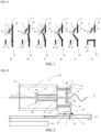
- the present invention relates to the field of medium voltage vacuum interrupters, which include components called vacuum interrupters or even vacuum interrupters.
- Vacuum interrupters are for example used in medium voltage electrical distribution devices, that is to say from 1 to 52 kV. Vacuum interrupters are notably associated with actuators to cut off the current in part of an electrical circuit.
- the opening of the vacuum interrupter is ensured only by the main switch during the opening stroke.
- There relative arrangement between the vacuum bulb and the main switch is therefore constrained.
- the kinematic connection between the vacuum interrupter and the main switch must be very precise. The dimensional tolerances on each element of the kinematic link must be low, taking into account the number of elements involved in the assembly.
- the document FR 3 044 162 A1 discloses a system for cutting off an electrical appliance according to the preamble of claim 1.
- the vacuum bulb is connected as a branch of a main circuit of one phase of the electrical appliance.
- the fixed electrode may include a rod extending along an axis and a contact body extending transversely to the axis.
- the fixed electrode can be formed by a plate.
- the paddle extends transversely to the stem.
- the cup is movable in translation along the axis of the rod.
- the elastic return means comprises a spring.
- the elastic return means is a spring.
- the spring is mounted stretched between a fixed wall of the cutting system and the movable cup.
- the movable cup comprises an orifice through which the rod of the movable electrode passes.
- the movable cup has the shape of a disc having an orifice in its center.
- the movable cup comprises a first disk-shaped portion, a second ring-shaped portion, the first portion and the second portion extending transversely to an axis, and a third cylindrical portion extending along the axis, the third portion connecting the first portion and the second portion, and the first portion comprises the orifice.
- a dimension of the orifice of the movable cup is less than a dimension of the pallet.
- the holding member is pivotally mounted around a pivot.
- the holding member is pivotally mounted, and the main switch of the main circuit is linked to a control element which includes a thrust zone configured to press on the holding member. so as to pivot the holding member out of its holding configuration.
- the holding member is configured to move from the holding configuration to the moving configuration under the action of an electromagnet.
- the cut-off system comprises a movable magnetic element kinematically linked to the main switch of the main circuit, the magnetic element being configured to circulate a magnetic flux in a control circuit of 'an electromagnet, the electromagnet being configured to move the holding member from the holding configuration to the moving configuration in response to movement of the movable magnetic element.
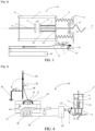
- the elastic return means 6 is in a state of maximum potential energy when the elastic return means 6 is in the immobilized position.
- the holding member 7 is in the holding configuration P1'.
- Contact 3 is then in the closed position P1 and allows the flow of current into the vacuum interrupter 2.
- the figure 2 corresponds to this state of the actuating device 50.
- the reference to the position of a movable element is indicated in parentheses.
- the cutting system comprises a cup 12 movable under the action of the elastic return means 6, the movable electrode 5 comprises a pallet 13 secured to the rod 10, and the movable cup 12 is configured to drive the pallet 13.
- This axial play J makes it possible to guarantee that the movable electrode 5 and the fixed electrode 4 are in good contact, that is to say that the electrical contact is well closed, when the elastic return means 6 is held by the retaining member 7.
- the sealing bellows 36 which surrounds the movable electrode 5 ensures a restoring force which presses the movable electrode 5 against the fixed electrode 4.
- An additional spring can be arranged at the inside the bellows 36 to increase the contact force.
- the movable cup 12 comprises an orifice 15 through which the rod 10 of the movable electrode 5 passes.
- the movable cup 12 comprises a first portion 16 in the shape of a disc, a second portion 17 in the form of a ring, the first portion 16 and the second portion 17 extending transversely to an axis D, and a third cylindrical portion 18 extending along the axis D, the third portion 18 connecting the first portion 16 and the second portion 17, and the first portion 16 comprises orifice 15.
- control circuit 26 of the electromagnet 25 is electrically powered by the main circuit 30 of the electrical appliance 1.
- the holding member 7 is movable in translation.
- the direction of translation is the axis D of the rod 10 of the movable electrode 5.
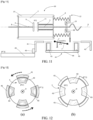
- the views of the Figure 12 are top views.
- the views of the figure 13 are side views.
- Part (a) of the Figure 12 and part (a) of the Figure 13 schematize the holding member 7 in the first position P1', in which the elastic return means 6 is immobilized.
- Part (b) of the Figure 12 and part (b) of the Figure 13 schematize the holding member 7 in the second position P2', in which the elastic return means 6 is no longer held.
- the elastic return means 6 of the mobile electrode 5 is held solely by magnetic forces.
- a magnetic component 41 linked to the main switch 20, is movable in rotation. The kinematics of connection between the main switch 20 and the magnetic component 41 have not been detailed, and are not represented in part (b) of the Figure 13 .
- the magnetic component 41 comprises 4 permanent magnets 43.
- Figure 12 schematizes the rotational movement of the magnetic component 41.
- a support part 46 is rigidly linked to the permanent magnets 43 as well as to the movable electrode 5.
- the support part 46, the movable component 41 and the permanent magnets 43 can form a magnetic circuit 42.
- the support part 46 and the mobile component 41 both participate in the looping of the field lines of the permanent magnets 43.
- the support part 46 is also linked to the spring 6.
- each permanent magnet 43 faces a portion of the magnetic component 41. There is thus a looping of the field lines, which ensures a holding force for the support part 46.
- the magnetic characteristics of the different elements of the magnetic circuit 42, as well as the value of the air gap, are chosen so that the holding force of the support part 46 is greater than the force exerted by the spring 6.
- the position shown in part (b) of the Figure 12 corresponds to a rotation of one eighth of a turn of the magnetic component 41.
- the permanent magnets 43 are no longer facing the element 41, and the looping of the field lines is negligible.
- the movement of the main switch 20 causes the release of the elastic return means 6 without using an electrical control.
Landscapes
- Physics & Mathematics (AREA)
- Electromagnetism (AREA)
- High-Tension Arc-Extinguishing Switches Without Spraying Means (AREA)
- Driving Mechanisms And Operating Circuits Of Arc-Extinguishing High-Tension Switches (AREA)
Claims (15)
- Abschaltsystem (50) eines elektrischen Geräts (1), das aufweist:- eine Vakuumröhre (2), die aufweist:- eine ortsfeste Elektrode (4),- eine bewegliche Elektrode (5), die konfiguriert ist, sich zu bewegen zwischen:- einer ersten Stellung (P1), Schließstellung genannt, in der die ortsfeste Elektrode (4) und die bewegliche Elektrode (5) miteinander in Kontakt sind, um einen Durchfluss von elektrischem Strom zu erlauben, und- einer zweiten Stellung (P2), Öffnungsstellung genannt, in der die ortsfeste Elektrode (4) und die bewegliche Elektrode (5) voneinander entfernt sind, um einen Durchfluss eines elektrischen Stroms zu verhindern,- eine elastische Rückstelleinrichtung (6), die konfiguriert ist, eine Antriebskraft auf die bewegliche Elektrode (5) auszuüben,- ein Halteorgan (7) der elastischen Rückstelleinrichtung (6) in Stellung, wobei das Halteorgan (7) konfiguriert ist, überzugehen:wobei das Abschaltsystem (50) konfiguriert ist, damit die bewegliche Elektrode (5) unter der Einwirkung der elastischen Rückstelleinrichtung (6) von der Schließstellung (P1) in die Öffnungsstellung (P2) übergeht, wenn das Halteorgan (7) seine Haltekonfiguration (P1') verlässt, wobei das Abschaltsystem (50) einen Hauptschalter (20) des elektrischen Geräts (1) aufweist, wobei der Hauptschalter (20) zwischen einer ersten Stellung (P1"), die einen Durchgang von elektrischem Strom in einen Hauptstromkreis (30) erlaubt, und einer zweiten Stellung (P2") beweglich ist, die den Durchgang von elektrischem Strom in den Hauptstromkreis (30) verhindert, und wobei der Hauptschalter (20) konfiguriert ist, damit das Halteorgan (7) seine Haltekonfiguration (P1) verlässt, wenn der Hauptschalter (20) von der ersten Stellung (P1 "), die den Durchgang des elektrischen Stroms erlaubt, in die zweite Stellung (P2") übergeht, die den Durchgang des elektrischen Stroms verhindert, und dadurch gekennzeichnet, dass im Abschaltsystem das Halteorgan (7) konfiguriert ist, unter der Einwirkung eines mit dem Hauptschalter (20) verbundenen magnetischen Bauteils (41) von der Haltekonfiguration (P1') in die Verschiebekonfiguration (P2') überzugehen.- von einer ersten Konfiguration (P1') Haltekonfiguration genannt, in der die elastische Rückstelleinrichtung (6) blockiert ist,- in eine zweite Konfiguration (P2'), Verschiebekonfiguration genannt, in der die elastische Rückstelleinrichtung (6) freigegeben ist,
- Abschaltsystem nach Anspruch 1, das einen unter der Einwirkung der elastischen Rückstelleinrichtung (6) beweglichen Federteller (12) aufweist, wobei die bewegliche Elektrode (5) einen Stab (10), der sich gemäß einer Achse (D) erstreckt, und eine fest mit dem Stab (10) verbundene Platte (13) aufweist, und wobei der bewegliche Federteller (12) konfiguriert ist, die Platte (13) anzutreiben.
- Abschaltsystem nach Anspruch 2, wobei die elastische Rückstelleinrichtung (6) eine Feder enthält, und wobei die Feder (6) zwischen einer ortsfesten Wand (14) des Abschaltsystems und dem beweglichen Federteller (12) komprimiert wird.
- Abschaltsystem nach Anspruch 2 oder 3, wobei der bewegliche Federteller (12) eine Öffnung (15) enthält, die vom Stab (10) der beweglichen Elektrode (5) durchquert wird, und wobei der bewegliche Federteller (12) einen ersten Teil (16) in Form einer Scheibe, einen zweiten Teil (17) in Form eines Rings, wobei der erste Teil (16) und der zweite Teil (17) sich quer zu einer Achse (D) erstrecken, und einen dritten zylindrischen Teil (18) enthält, der sich gemäß der Achse (D) erstreckt, wobei der dritte Teil (18) den ersten Teil (16) und den zweiten Teil (17) verbindet, wobei der erste Teil (16) die Öffnung (15) enthält.
- Abschaltsystem nach einem der vorhergehenden Ansprüche, wobei das Halteorgan (7) um eine Schwenkachse (19) schwenkbar montiert ist.
- Abschaltsystem nach einem der vorhergehenden Ansprüche, wobei das Halteorgan (7) schwenkbar montiert ist, und wobei der Hauptschalter (20) des Hauptstromkreises (30) mit einem Steuerelement (40) verbunden ist, das einen Schubbereich (21) aufweist, der konfiguriert ist, auf das Halteorgan (7) zu drücken, um das Halteorgan (7) aus seiner Haltestellung (P1') schwenken zu lassen.
- Abschaltsystem nach einem der Ansprüche 1 bis 5, wobei das Halteorgan (7) konfiguriert ist, unter der Einwirkung eines Elektromagneten (25) von der Haltekonfiguration (P1') in die Verschiebekonfiguration (P2') überzugehen.
- Abschaltsystem nach Anspruch 7, das ein bewegliches magnetisches Element (23) aufweist, das kinematisch mit dem Hauptschalter (20) des Hauptstromkreises (30) verbunden ist, wobei das magnetische Element (23) konfiguriert ist, einen magnetischen Fluss in einem Steuerstromkreis (26) des Elektromagneten (25) fließen zu lassen, wobei der Elektromagnet (25) konfiguriert ist, als Antwort auf eine Verschiebung des beweglichen magnetischen Elements (23) das Halteorgan (7) von der Haltekonfiguration (P1') in die Verschiebekonfiguration (P2') übergehen zu lassen.
- Abschaltsystem nach Anspruch 8, wobei der Hauptschalter (20) des Hauptstromkreises (30) konfiguriert ist, einen Steuerstromkreis (26) des Elektromagneten (25) mit Strom zu versorgen, wobei der Elektromagnet (25) konfiguriert ist, als Antwort auf die vom Hauptschalter (20) empfangene Stromversorgung das Halteorgan (7) von der Haltekonfiguration in die Verschiebekonfiguration übergehen zu lassen.
- Abschaltsystem nach Anspruch 9, wobei der Steuerstromkreis (26) des Elektromagneten (25) vom Hauptstromkreis (30) des elektrischen Geräts (1) mit Strom versorgt wird.
- Abschaltsystem nach einem der vorhergehenden Ansprüche, wobei das Halteorgan (7) einen Dauermagnet (32) enthält, der konfiguriert ist, eine Magnetkraft auf eine mit der bewegliche Elektrode (5) verbundene magnetische Platte (24) auszuüben, und wobei das Halteorgan (7) einen Elektromagnet (25) enthält, der konfiguriert ist, ein einem vom Dauermagnet (32) erzeugten Magnetfeld entgegengesetztes Magnetfeld auszuüben.
- Abschaltsystem nach einem der vorhergehenden Ansprüche, wobei das magnetische Bauteil (41) ein Dauermagnet ist, der konfiguriert ist, das Halteorgan (7) anzutreiben.
- Abschaltsystem nach einem der vorhergehenden Ansprüche, wobei das magnetische Bauteil (41) ein Magnetkern ist, der konfiguriert ist, ein Magnetfeld in einem Magnetkreis (42) zu kanalisieren.
- Abschaltsystem nach einem der vorhergehenden Ansprüche, wobei der Hauptschalter (20) konfiguriert ist, die bewegliche Elektrode (5) in die Schließstellung der Vakuumröhre (2) übergehen zu lassen, und auch konfiguriert ist, die elastische Rückstelleinrichtung (6) in eine Stellung übergehen zu lassen, in der die potentielle Energie der elastischen Rückstelleinrichtung (6) höher als die oder gleich der potentiellen Energie ist, die der Haltekonfiguration (P1') entspricht, und ebenfalls konfiguriert ist, das Halteorgan (7) in seine Haltekonfiguration (P1) zu verschieben, wenn der Hauptschalter (20) von der Stellung (P2"), die den Durchgang des Stroms in den Hauptstromkreis (30) verhindert, in die Stellung (P1") übergeht, die den Durchgang des Stroms in den Hauptstromkreis (30) erlaubt.
- Elektrisches Gerät (1), das aufweist:- einen Hauptschalter (20) eines Hauptstromkreises (30),- ein Abschaltsystem (50) nach einem der vorhergehenden Ansprüche,wobei die Vakuumröhre (2) parallel zum Hauptschalter (20) angeordnet ist.
Applications Claiming Priority (1)
| Application Number | Priority Date | Filing Date | Title |
|---|---|---|---|
| FR2102954A FR3121267A1 (fr) | 2021-03-24 | 2021-03-24 | Système de coupure d’un appareil électrique |
Publications (3)
| Publication Number | Publication Date |
|---|---|
| EP4064309A1 EP4064309A1 (de) | 2022-09-28 |
| EP4064309B1 true EP4064309B1 (de) | 2024-07-10 |
| EP4064309C0 EP4064309C0 (de) | 2024-07-10 |
Family
ID=75850342
Family Applications (1)
| Application Number | Title | Priority Date | Filing Date |
|---|---|---|---|
| EP22161562.8A Active EP4064309B1 (de) | 2021-03-24 | 2022-03-11 | System zur abschaltung eines elektrischen geräts |
Country Status (4)
| Country | Link |
|---|---|
| US (1) | US11948765B2 (de) |
| EP (1) | EP4064309B1 (de) |
| CN (1) | CN115132553A (de) |
| FR (1) | FR3121267A1 (de) |
Family Cites Families (17)
| Publication number | Priority date | Publication date | Assignee | Title |
|---|---|---|---|---|
| FR2868197B1 (fr) * | 2004-03-25 | 2006-05-19 | Areva T & D Sa | Dispositif de commande pour l'actionnement coordonne d'au moins deux appareils de commutation dont un est a coupure dans le vide |
| DE102005002139B4 (de) | 2005-01-13 | 2007-01-25 | Siemens Ag | Dreistellungsschalter mit Kurvenscheibe |
| FR2937786B1 (fr) * | 2008-10-29 | 2010-12-24 | Areva T & D Sa | Interrupteur de courant sur une ligne electrique comprenant une ampoule a vide |
| FR2946180B1 (fr) | 2009-05-26 | 2012-12-14 | Areva T & D Sa | Dispositif d'accrochage et de verrouillage interne a un interrupteur ou a un disjoncteur. |
| FR2970809B1 (fr) | 2011-01-25 | 2013-02-22 | Schneider Electric Ind Sas | Dispositif de coupure moyenne tension comprenant une ampoule a vide |
| FR2972290B1 (fr) | 2011-03-02 | 2013-04-19 | Schneider Electric Ind Sas | Dispositif de coupure de courant sur une ligne electrique a derivation et ampoule a vide |
| DE102011017815B3 (de) | 2011-04-29 | 2012-10-11 | Siemens Aktiengesellschaft | Schaltgerät |
| DE102011087630B4 (de) | 2011-12-02 | 2016-11-03 | Siemens Aktiengesellschaft | Schaltgerät |
| DE102012200962B4 (de) | 2012-01-24 | 2018-07-26 | Siemens Aktiengesellschaft | Schaltgerät, insbesondere Lasttrennschalter, für Mittelspannungs-Schaltanlagen |
| CN104335312B (zh) | 2012-06-25 | 2017-05-24 | 西门子公司 | 用于中压开关设备的三工位负荷隔离开关 |
| DE102013217834B4 (de) | 2013-09-06 | 2022-01-20 | Siemens Aktiengesellschaft | Schaltgerät und Verfahren zum Schalten eines solchen Schaltgerätes |
| ES2687030T3 (es) | 2015-01-15 | 2018-10-23 | Schneider Electric Industries Sas | Sistema de ruptura de derivación |
| EP3046129B1 (de) | 2015-01-15 | 2019-09-11 | Schneider Electric Industries SAS | Lastschaltsystem mit parallelem Strompfad |
| US9679724B2 (en) | 2015-07-13 | 2017-06-13 | Eaton Corporation | Component for electric power system, and contact assembly and open air arcing elimination method therefor |
| FR3044162B1 (fr) * | 2015-11-20 | 2023-05-12 | Schneider Electric Ind Sas | Appareil de protection electrique et en particulier disjoncteur electrique moyenne tension |
| FR3080946B1 (fr) * | 2018-05-07 | 2021-02-19 | Alstom Transp Tech | Disjoncteur a interrupteur a vide |
| FR3093226B1 (fr) | 2019-02-25 | 2021-01-22 | Schneider Electric Ind Sas | Système d'actionnement pour une ampoule à vide |
-
2021
- 2021-03-24 FR FR2102954A patent/FR3121267A1/fr not_active Ceased
-
2022
- 2022-03-11 EP EP22161562.8A patent/EP4064309B1/de active Active
- 2022-03-16 US US17/695,888 patent/US11948765B2/en active Active
- 2022-03-24 CN CN202210298161.8A patent/CN115132553A/zh active Pending
Also Published As
| Publication number | Publication date |
|---|---|
| US11948765B2 (en) | 2024-04-02 |
| US20220310339A1 (en) | 2022-09-29 |
| CN115132553A (zh) | 2022-09-30 |
| FR3121267A1 (fr) | 2022-09-30 |
| EP4064309C0 (de) | 2024-07-10 |
| EP4064309A1 (de) | 2022-09-28 |
Similar Documents
| Publication | Publication Date | Title |
|---|---|---|
| FR2728101A1 (fr) | Commutateur inverseur | |
| EP1185995A1 (de) | Steuervorrichtung zum öffnen und/oder zum schliessen, insbesondere für ein schaltgerät wie ein schutzschalter, und ein schutzschalter ausgerüstet mit dieser vorrichtung | |
| FR2953322A1 (fr) | Interrupteur electrique formant coupe-circuit a actionnement rapide | |
| EP0877405A1 (de) | Lastschalter mit Trennschalter | |
| EP4064309B1 (de) | System zur abschaltung eines elektrischen geräts | |
| WO2003005394A1 (fr) | Appareillage electrique de coupure et de sectionnement comportant une ampoule sous vide | |
| WO2013087661A1 (fr) | Dispositif d'entrainement d'un ensemble conducteur d'un sectionneur, permettant le deplacement de l'ensemble a vitesse variable | |
| EP1029334B1 (de) | Anlasser-schütz mit mehrteiligen magnetkern | |
| EP4330999B1 (de) | Stromunterbrechungssystem eines elektrischen geräts | |
| EP4465326B1 (de) | Steuerungsmechanismus für eine elektrische schaltvorrichtung | |
| CH668498A5 (fr) | Electro-aimant a courant continu a mouvement de translation. | |
| WO2002065497A1 (fr) | Dispositif de manoeuvre bistable en translation d'un axe mobile | |
| WO1984002802A1 (fr) | Interrupteur a fermeture et ouverture commandees et a ouverture automatique en cas de surcharge de courant | |
| EP0752152B1 (de) | Magnetischer betätiger mit mehrfach luftspalten | |
| EP4020514B1 (de) | Elektrischer unterbrechungskontakt | |
| EP3608928A1 (de) | Elektromagnetisches stellglied, elektrisches schaltgerät, das ein solches stellglied umfasst | |
| WO2023111451A1 (fr) | Contacteur de puissance a double contacts | |
| WO2005001868A1 (fr) | Appareil electrique interrupteur a plusieurs actionneurs. | |
| EP4492418A1 (de) | Abschaltvorrichtung für einen elektrischen strom, batteriemodul mit einer solchen vorrichtung und kraftfahrzeug mit einem solchen batteriemodul | |
| EP1697955B1 (de) | Elektromechanischer aktor | |
| FR2965096A1 (fr) | Disjoncteur comportant un dispositif d'insertion de resistance dans une ligne de transport de courant | |
| FR2820877A1 (fr) | Dispositif de manoeuvre bistable en translation d'un axe mobile | |
| WO2013083646A1 (fr) | Dispositif électrique d'entraînement en translation d'une pièce, appareil de commutation électrique comportant un tel dispositif et inverseur triphasé comprenant un tel appareil | |
| FR2574985A1 (fr) | Micro-interrupteur | |
| WO2004088188A2 (fr) | Dispositif d'actionnement electromagnetique |
Legal Events
| Date | Code | Title | Description |
|---|---|---|---|
| PUAI | Public reference made under article 153(3) epc to a published international application that has entered the european phase |
Free format text: ORIGINAL CODE: 0009012 |
|
| STAA | Information on the status of an ep patent application or granted ep patent |
Free format text: STATUS: THE APPLICATION HAS BEEN PUBLISHED |
|
| AK | Designated contracting states |
Kind code of ref document: A1 Designated state(s): AL AT BE BG CH CY CZ DE DK EE ES FI FR GB GR HR HU IE IS IT LI LT LU LV MC MK MT NL NO PL PT RO RS SE SI SK SM TR |
|
| STAA | Information on the status of an ep patent application or granted ep patent |
Free format text: STATUS: REQUEST FOR EXAMINATION WAS MADE |
|
| 17P | Request for examination filed |
Effective date: 20230324 |
|
| RBV | Designated contracting states (corrected) |
Designated state(s): AL AT BE BG CH CY CZ DE DK EE ES FI FR GB GR HR HU IE IS IT LI LT LU LV MC MK MT NL NO PL PT RO RS SE SI SK SM TR |
|
| GRAP | Despatch of communication of intention to grant a patent |
Free format text: ORIGINAL CODE: EPIDOSNIGR1 |
|
| STAA | Information on the status of an ep patent application or granted ep patent |
Free format text: STATUS: GRANT OF PATENT IS INTENDED |
|
| RIC1 | Information provided on ipc code assigned before grant |
Ipc: H01H 33/666 20060101ALI20240328BHEP Ipc: H01H 33/12 20060101ALI20240328BHEP Ipc: H01H 31/00 20060101AFI20240328BHEP |
|
| INTG | Intention to grant announced |
Effective date: 20240424 |
|
| GRAS | Grant fee paid |
Free format text: ORIGINAL CODE: EPIDOSNIGR3 |
|
| GRAA | (expected) grant |
Free format text: ORIGINAL CODE: 0009210 |
|
| STAA | Information on the status of an ep patent application or granted ep patent |
Free format text: STATUS: THE PATENT HAS BEEN GRANTED |
|
| AK | Designated contracting states |
Kind code of ref document: B1 Designated state(s): AL AT BE BG CH CY CZ DE DK EE ES FI FR GB GR HR HU IE IS IT LI LT LU LV MC MK MT NL NO PL PT RO RS SE SI SK SM TR |
|
| REG | Reference to a national code |
Ref country code: CH Ref legal event code: EP |
|
| REG | Reference to a national code |
Ref country code: DE Ref legal event code: R096 Ref document number: 602022004396 Country of ref document: DE |
|
| U01 | Request for unitary effect filed |
Effective date: 20240710 |
|
| U07 | Unitary effect registered |
Designated state(s): AT BE BG DE DK EE FI FR IT LT LU LV MT NL PT RO SE SI Effective date: 20240902 |
|
| PG25 | Lapsed in a contracting state [announced via postgrant information from national office to epo] |
Ref country code: NO Free format text: LAPSE BECAUSE OF FAILURE TO SUBMIT A TRANSLATION OF THE DESCRIPTION OR TO PAY THE FEE WITHIN THE PRESCRIBED TIME-LIMIT Effective date: 20241010 |
|
| PG25 | Lapsed in a contracting state [announced via postgrant information from national office to epo] |
Ref country code: GR Free format text: LAPSE BECAUSE OF FAILURE TO SUBMIT A TRANSLATION OF THE DESCRIPTION OR TO PAY THE FEE WITHIN THE PRESCRIBED TIME-LIMIT Effective date: 20241011 Ref country code: PL Free format text: LAPSE BECAUSE OF FAILURE TO SUBMIT A TRANSLATION OF THE DESCRIPTION OR TO PAY THE FEE WITHIN THE PRESCRIBED TIME-LIMIT Effective date: 20240710 |
|
| PG25 | Lapsed in a contracting state [announced via postgrant information from national office to epo] |
Ref country code: IS Free format text: LAPSE BECAUSE OF FAILURE TO SUBMIT A TRANSLATION OF THE DESCRIPTION OR TO PAY THE FEE WITHIN THE PRESCRIBED TIME-LIMIT Effective date: 20241110 |
|
| PG25 | Lapsed in a contracting state [announced via postgrant information from national office to epo] |
Ref country code: HR Free format text: LAPSE BECAUSE OF FAILURE TO SUBMIT A TRANSLATION OF THE DESCRIPTION OR TO PAY THE FEE WITHIN THE PRESCRIBED TIME-LIMIT Effective date: 20240710 |
|
| PG25 | Lapsed in a contracting state [announced via postgrant information from national office to epo] |
Ref country code: ES Free format text: LAPSE BECAUSE OF FAILURE TO SUBMIT A TRANSLATION OF THE DESCRIPTION OR TO PAY THE FEE WITHIN THE PRESCRIBED TIME-LIMIT Effective date: 20240710 Ref country code: RS Free format text: LAPSE BECAUSE OF FAILURE TO SUBMIT A TRANSLATION OF THE DESCRIPTION OR TO PAY THE FEE WITHIN THE PRESCRIBED TIME-LIMIT Effective date: 20241010 |
|
| PG25 | Lapsed in a contracting state [announced via postgrant information from national office to epo] |
Ref country code: RS Free format text: LAPSE BECAUSE OF FAILURE TO SUBMIT A TRANSLATION OF THE DESCRIPTION OR TO PAY THE FEE WITHIN THE PRESCRIBED TIME-LIMIT Effective date: 20241010 Ref country code: PL Free format text: LAPSE BECAUSE OF FAILURE TO SUBMIT A TRANSLATION OF THE DESCRIPTION OR TO PAY THE FEE WITHIN THE PRESCRIBED TIME-LIMIT Effective date: 20240710 Ref country code: NO Free format text: LAPSE BECAUSE OF FAILURE TO SUBMIT A TRANSLATION OF THE DESCRIPTION OR TO PAY THE FEE WITHIN THE PRESCRIBED TIME-LIMIT Effective date: 20241010 Ref country code: IS Free format text: LAPSE BECAUSE OF FAILURE TO SUBMIT A TRANSLATION OF THE DESCRIPTION OR TO PAY THE FEE WITHIN THE PRESCRIBED TIME-LIMIT Effective date: 20241110 Ref country code: HR Free format text: LAPSE BECAUSE OF FAILURE TO SUBMIT A TRANSLATION OF THE DESCRIPTION OR TO PAY THE FEE WITHIN THE PRESCRIBED TIME-LIMIT Effective date: 20240710 Ref country code: GR Free format text: LAPSE BECAUSE OF FAILURE TO SUBMIT A TRANSLATION OF THE DESCRIPTION OR TO PAY THE FEE WITHIN THE PRESCRIBED TIME-LIMIT Effective date: 20241011 Ref country code: ES Free format text: LAPSE BECAUSE OF FAILURE TO SUBMIT A TRANSLATION OF THE DESCRIPTION OR TO PAY THE FEE WITHIN THE PRESCRIBED TIME-LIMIT Effective date: 20240710 |
|
| PG25 | Lapsed in a contracting state [announced via postgrant information from national office to epo] |
Ref country code: SM Free format text: LAPSE BECAUSE OF FAILURE TO SUBMIT A TRANSLATION OF THE DESCRIPTION OR TO PAY THE FEE WITHIN THE PRESCRIBED TIME-LIMIT Effective date: 20240710 |
|
| PG25 | Lapsed in a contracting state [announced via postgrant information from national office to epo] |
Ref country code: CZ Free format text: LAPSE BECAUSE OF FAILURE TO SUBMIT A TRANSLATION OF THE DESCRIPTION OR TO PAY THE FEE WITHIN THE PRESCRIBED TIME-LIMIT Effective date: 20240710 |
|
| PG25 | Lapsed in a contracting state [announced via postgrant information from national office to epo] |
Ref country code: SK Free format text: LAPSE BECAUSE OF FAILURE TO SUBMIT A TRANSLATION OF THE DESCRIPTION OR TO PAY THE FEE WITHIN THE PRESCRIBED TIME-LIMIT Effective date: 20240710 |
|
| U20 | Renewal fee for the european patent with unitary effect paid |
Year of fee payment: 4 Effective date: 20250325 |
|
| PLBE | No opposition filed within time limit |
Free format text: ORIGINAL CODE: 0009261 |
|
| STAA | Information on the status of an ep patent application or granted ep patent |
Free format text: STATUS: NO OPPOSITION FILED WITHIN TIME LIMIT |
|
| 26N | No opposition filed |
Effective date: 20250411 |
|
| PG25 | Lapsed in a contracting state [announced via postgrant information from national office to epo] |
Ref country code: MC Free format text: LAPSE BECAUSE OF FAILURE TO SUBMIT A TRANSLATION OF THE DESCRIPTION OR TO PAY THE FEE WITHIN THE PRESCRIBED TIME-LIMIT Effective date: 20240710 |
|
| REG | Reference to a national code |
Ref country code: CH Ref legal event code: H13 Free format text: ST27 STATUS EVENT CODE: U-0-0-H10-H13 (AS PROVIDED BY THE NATIONAL OFFICE) Effective date: 20251023 |
|
| PG25 | Lapsed in a contracting state [announced via postgrant information from national office to epo] |
Ref country code: CH Free format text: LAPSE BECAUSE OF NON-PAYMENT OF DUE FEES Effective date: 20250331 |
|
| PG25 | Lapsed in a contracting state [announced via postgrant information from national office to epo] |
Ref country code: IE Free format text: LAPSE BECAUSE OF NON-PAYMENT OF DUE FEES Effective date: 20250311 |