EP4064003B1 - Leistungseinstellungsverfahren und -gerät für prozessor - Google Patents
Leistungseinstellungsverfahren und -gerät für prozessor Download PDFInfo
- Publication number
- EP4064003B1 EP4064003B1 EP20900963.8A EP20900963A EP4064003B1 EP 4064003 B1 EP4064003 B1 EP 4064003B1 EP 20900963 A EP20900963 A EP 20900963A EP 4064003 B1 EP4064003 B1 EP 4064003B1
- Authority
- EP
- European Patent Office
- Prior art keywords
- processor
- tdp
- processing module
- power
- computer apparatus
- Prior art date
- Legal status (The legal status is an assumption and is not a legal conclusion. Google has not performed a legal analysis and makes no representation as to the accuracy of the status listed.)
- Active
Links
Images



Classifications
-
- G—PHYSICS
- G06—COMPUTING OR CALCULATING; COUNTING
- G06F—ELECTRIC DIGITAL DATA PROCESSING
- G06F1/00—Details not covered by groups G06F3/00 - G06F13/00 and G06F21/00
- G06F1/16—Constructional details or arrangements
- G06F1/20—Cooling means
- G06F1/206—Cooling means comprising thermal management
-
- G—PHYSICS
- G06—COMPUTING OR CALCULATING; COUNTING
- G06F—ELECTRIC DIGITAL DATA PROCESSING
- G06F1/00—Details not covered by groups G06F3/00 - G06F13/00 and G06F21/00
- G06F1/26—Power supply means, e.g. regulation thereof
- G06F1/28—Supervision thereof, e.g. detecting power-supply failure by out of limits supervision
-
- G—PHYSICS
- G06—COMPUTING OR CALCULATING; COUNTING
- G06F—ELECTRIC DIGITAL DATA PROCESSING
- G06F1/00—Details not covered by groups G06F3/00 - G06F13/00 and G06F21/00
- G06F1/26—Power supply means, e.g. regulation thereof
- G06F1/32—Means for saving power
- G06F1/3203—Power management, i.e. event-based initiation of a power-saving mode
- G06F1/3206—Monitoring of events, devices or parameters that trigger a change in power modality
-
- G—PHYSICS
- G06—COMPUTING OR CALCULATING; COUNTING
- G06F—ELECTRIC DIGITAL DATA PROCESSING
- G06F1/00—Details not covered by groups G06F3/00 - G06F13/00 and G06F21/00
- G06F1/26—Power supply means, e.g. regulation thereof
- G06F1/32—Means for saving power
- G06F1/3203—Power management, i.e. event-based initiation of a power-saving mode
- G06F1/3234—Power saving characterised by the action undertaken
- G06F1/324—Power saving characterised by the action undertaken by lowering clock frequency
-
- G—PHYSICS
- G06—COMPUTING OR CALCULATING; COUNTING
- G06F—ELECTRIC DIGITAL DATA PROCESSING
- G06F1/00—Details not covered by groups G06F3/00 - G06F13/00 and G06F21/00
- G06F1/26—Power supply means, e.g. regulation thereof
- G06F1/32—Means for saving power
- G06F1/3203—Power management, i.e. event-based initiation of a power-saving mode
- G06F1/3234—Power saving characterised by the action undertaken
- G06F1/3243—Power saving in microcontroller unit
-
- G—PHYSICS
- G06—COMPUTING OR CALCULATING; COUNTING
- G06F—ELECTRIC DIGITAL DATA PROCESSING
- G06F1/00—Details not covered by groups G06F3/00 - G06F13/00 and G06F21/00
- G06F1/26—Power supply means, e.g. regulation thereof
- G06F1/32—Means for saving power
- G06F1/3203—Power management, i.e. event-based initiation of a power-saving mode
- G06F1/3234—Power saving characterised by the action undertaken
- G06F1/325—Power saving in peripheral device
-
- G—PHYSICS
- G06—COMPUTING OR CALCULATING; COUNTING
- G06F—ELECTRIC DIGITAL DATA PROCESSING
- G06F1/00—Details not covered by groups G06F3/00 - G06F13/00 and G06F21/00
- G06F1/26—Power supply means, e.g. regulation thereof
- G06F1/32—Means for saving power
- G06F1/3203—Power management, i.e. event-based initiation of a power-saving mode
- G06F1/3234—Power saving characterised by the action undertaken
- G06F1/3296—Power saving characterised by the action undertaken by lowering the supply or operating voltage
-
- G—PHYSICS
- G06—COMPUTING OR CALCULATING; COUNTING
- G06F—ELECTRIC DIGITAL DATA PROCESSING
- G06F11/00—Error detection; Error correction; Monitoring
- G06F11/07—Responding to the occurrence of a fault, e.g. fault tolerance
- G06F11/0703—Error or fault processing not based on redundancy, i.e. by taking additional measures to deal with the error or fault not making use of redundancy in operation, in hardware, or in data representation
- G06F11/0751—Error or fault detection not based on redundancy
- G06F11/0754—Error or fault detection not based on redundancy by exceeding limits
- G06F11/076—Error or fault detection not based on redundancy by exceeding limits by exceeding a count or rate limit, e.g. word- or bit count limit
-
- G—PHYSICS
- G06—COMPUTING OR CALCULATING; COUNTING
- G06F—ELECTRIC DIGITAL DATA PROCESSING
- G06F11/00—Error detection; Error correction; Monitoring
- G06F11/30—Monitoring
- G06F11/3003—Monitoring arrangements specially adapted to the computing system or computing system component being monitored
- G06F11/3024—Monitoring arrangements specially adapted to the computing system or computing system component being monitored where the computing system component is a central processing unit [CPU]
-
- G—PHYSICS
- G06—COMPUTING OR CALCULATING; COUNTING
- G06F—ELECTRIC DIGITAL DATA PROCESSING
- G06F11/00—Error detection; Error correction; Monitoring
- G06F11/30—Monitoring
- G06F11/3051—Monitoring arrangements for monitoring the configuration of the computing system or of the computing system component, e.g. monitoring the presence of processing resources, peripherals, I/O links, software programs
-
- G—PHYSICS
- G06—COMPUTING OR CALCULATING; COUNTING
- G06F—ELECTRIC DIGITAL DATA PROCESSING
- G06F11/00—Error detection; Error correction; Monitoring
- G06F11/30—Monitoring
- G06F11/3058—Monitoring arrangements for monitoring environmental properties or parameters of the computing system or of the computing system component, e.g. monitoring of power, currents, temperature, humidity, position, vibrations
-
- G—PHYSICS
- G06—COMPUTING OR CALCULATING; COUNTING
- G06F—ELECTRIC DIGITAL DATA PROCESSING
- G06F11/00—Error detection; Error correction; Monitoring
- G06F11/30—Monitoring
- G06F11/34—Recording or statistical evaluation of computer activity, e.g. of down time, of input/output operation ; Recording or statistical evaluation of user activity, e.g. usability assessment
- G06F11/3409—Recording or statistical evaluation of computer activity, e.g. of down time, of input/output operation ; Recording or statistical evaluation of user activity, e.g. usability assessment for performance assessment
-
- G—PHYSICS
- G06—COMPUTING OR CALCULATING; COUNTING
- G06F—ELECTRIC DIGITAL DATA PROCESSING
- G06F11/00—Error detection; Error correction; Monitoring
- G06F11/30—Monitoring
- G06F11/34—Recording or statistical evaluation of computer activity, e.g. of down time, of input/output operation ; Recording or statistical evaluation of user activity, e.g. usability assessment
- G06F11/3409—Recording or statistical evaluation of computer activity, e.g. of down time, of input/output operation ; Recording or statistical evaluation of user activity, e.g. usability assessment for performance assessment
- G06F11/3419—Recording or statistical evaluation of computer activity, e.g. of down time, of input/output operation ; Recording or statistical evaluation of user activity, e.g. usability assessment for performance assessment by assessing time
-
- Y—GENERAL TAGGING OF NEW TECHNOLOGICAL DEVELOPMENTS; GENERAL TAGGING OF CROSS-SECTIONAL TECHNOLOGIES SPANNING OVER SEVERAL SECTIONS OF THE IPC; TECHNICAL SUBJECTS COVERED BY FORMER USPC CROSS-REFERENCE ART COLLECTIONS [XRACs] AND DIGESTS
- Y02—TECHNOLOGIES OR APPLICATIONS FOR MITIGATION OR ADAPTATION AGAINST CLIMATE CHANGE
- Y02D—CLIMATE CHANGE MITIGATION TECHNOLOGIES IN INFORMATION AND COMMUNICATION TECHNOLOGIES [ICT], I.E. INFORMATION AND COMMUNICATION TECHNOLOGIES AIMING AT THE REDUCTION OF THEIR OWN ENERGY USE
- Y02D10/00—Energy efficient computing, e.g. low power processors, power management or thermal management
Definitions
- This application relates to the field of semiconductor chips, and in particular, to a method for adjusting power of a processor.
- a heat dissipation capability of a chip is one of main bottlenecks that limit increase of a frequency and a quantity of cores of the chip.
- the processor is usually limited to a specific power consumption range during working. Performance of the processor is mainly affected by power of the processor. In other words, the performance of the processor is affected by the power consumption range of the processor.
- thermal design power Thermal Design Power
- TDP Thermal Design Power
- the TDP helps protect the processor from being damaged due to overheating, the TDP also limits maximum performance of the processor.
- short-term service traffic bursts in many service scenarios.
- a processor with a computing capability far exceeding an average computing capability requirement needs to be used.
- costs for enterprises to purchase hardware devices are greatly increased.
- US 2013/159201 A1 describes changing the thermal design power, TDP, of a processor using the BIOS (user configured).
- US 2012/023345 A1 discloses a multi-core processor system wherein each core has certain number of thermal power credits which can be allocated (credited) to a different core in case of the power target (which is the thermal design power value for the die) of the different core is exceeded.
- US 2015/346798 A1 describes a semiconductor chip i.e. system-on-a-chip for on-die power management system comprising a power manager that determines a ratio of first thermal design power value to second thermal design power value, where a headroom is determined based on the ratio.
- US 2011/055596 A1 discloses a thermal management system which compares a metric representing a combined measure of power used by a CPU and power used by a GPU to a shared power budget, wherein a state of the CPU and a state of the GPU are regulated to maintain the metric within the shared power budget.
- this application provides a method for adjusting power of a processor.
- usage of the processor exceeds a threshold, the power of the processor can be adjusted, so that adjusted power of the processor exceeds TDP corresponding to the processor, thereby improving computing performance of the processor in a short time.
- this application provides a method for adjusting power of a processor.
- the method is used in a computer apparatus, the computer apparatus comprises the processor, and the method comprises: determining that usage of the processor exceeds a first threshold; and when the usage of the processor exceeds the first threshold adjusting TDP of the processor, where adjusted TDP of the processor is greater than the preset TDP of the processor, wherein after the adjusting TDP of the processor, the method further comprises: monitoring quantity of errors that occur in the processor within a specified period of time and reducing the TDP of the processor when the quantity of errors that occur in the processor within the specified period of time is greater than or equal to a fourth threshold.
- the computer apparatus can temporarily adjust the TDP of the processor when the usage of the processor reaches a specific degree. Because the processor usually has a power protection function, when power of the processor reaches or approaches the TDP, the power of the processor is reduced in a manner such as reducing a frequency. Therefore, in this method, the TDP of the processor is increased, so that the power of the processor can exceed the preset TDP without triggering the power protection function, thereby meeting a requirement of a current service for performance of the processor.
- the method before the adjusting TDP of the processor, the method further includes: obtaining a current temperature of the processor; and determining that a difference between a highest temperature of the processor and the current temperature of the processor is greater than or equal to a second threshold, such that the power of the processor can still be increased in this case.
- the method before the adjusting TDP of the processor, the method further includes: obtaining a current rotational speed of a fan, where the fan is configured to dissipate heat for the processor; and determining that a ratio of the current rotational speed of the fan to a maximum rotational speed of the fan is less than or equal to a third threshold, such that the power of the processor can still be increased in this case.
- the method before the TDP of the processor is adjusted, whether the computer apparatus has a margin of a heat dissipation capability of the processor can be first determined, so that the temperature of the processor can still be kept within a safe range after the power of the processor increases, thereby improving running stability of the computer apparatus.
- the method before the adjusting TDP of the processor, the method further includes: determining an increment in TDP of the processor; sending an electric energy request to a power supply controller, where the electric energy request carries information about the increment in TDP of the processor; and receiving a response sent by the power supply controller, where the response is used to indicate that the power supply controller has allocated electric energy corresponding to the increment in TDP of the processor to the computer apparatus.
- the corresponding electric energy can be first requested from the power supply controller based on the increment in TDP of the processor, so that sufficient electric energy can be provided for the processor with increased power, thereby improving running stability of the computer apparatus.
- the quantity of errors occur in the processor within the specified period of time is monitored to monitor working reliability of the processor.
- the TDP of the processor is reduced, thereby improving running reliability of the computer apparatus.
- the method further includes: monitoring duration in which the processor runs at power exceeding the preset TDP; and sending an alarm when the duration in which the processor runs at the power exceeding the preset TDP exceeds a fifth threshold.
- the running duration of the processor at the power exceeding the preset TDP can be monitored.
- the processor runs at the power for a long time running reliability of the computer apparatus and a service life of the processor are affected. Therefore, the alarm needs to be sent to notify a user to select a processor with higher rated power.
- a step of adjusting TDP of the processor specifically includes: determining the adjusted TDP of the processor based on the difference between the highest temperature of the processor and the current temperature of the processor and the ratio of the current rotational speed of the fan to the maximum rotational speed of the fan.
- the TDP added by the processor can be determined based on the margin of the heat dissipation capability of the processor in the computer apparatus, thereby improving running stability of the computer apparatus and running efficiency of the processor.
- the adjusting TDP of the processor includes: adjusting the TDP of the processor by using a basic input/output system or a baseband management controller in the computer apparatus.
- the computer apparatus can adjust power of the processor in a manner of decreasing the current obtained by the processor through monitoring.
- the current obtained by the processor through monitoring can be modified. Therefore, when actual power of the processor has exceeded preset TDP, the obtained power of the processor through monitoring has not exceeded the preset TDP, so that the power of the processor can be adjusted without triggering a power protection function.
- this application provides a computer apparatus.
- the computer apparatus includes: a processing module; a monitor module, configured to determine that usage of the processing module exceeds a first threshold; and an adjustment module, configured to adjust TDP of the processing module when the usage of the processing module exceeds the first threshold, wherein adjusted TDP of the processing module is greater than the preset TDP of the processing module, wherein the monitor module is further configured to: monitor a quantity of errors that occur in the processing module within a specified period of time after the adjustment module adjusts the TDP of the processing module and the adjustment module is further configured to: reduce the TDP of the processing module when the quantity of errors that occur in the processing module within the specified period of time is greater than or equal to a fourth threshold.
- the monitor module is further configured to: obtain a current temperature of the processing module before the adjustment module adjusts the TDP of the processing module; and determine that a difference between a highest temperature of the processing module and the current temperature of the processing module is greater than or equal to a second threshold.
- the monitor module is further configured to: obtain a current rotational speed of a fan before the adjustment module adjusts the TDP of the processing module, where the fan is configured to dissipate heat for the processing module; and determine that a ratio of the current rotational speed of the fan to a maximum rotational speed of the fan is less than or equal to a third threshold.
- the monitor module is further configured to: determine an increment in TDP of the processing module before the adjustment module adjusts the TDP of the processing module; send an electric energy request to a power supply controller, where the electric energy request carries information about the increment in TDP of the processing module; and receive a response sent by the power supply controller, where the response is used to indicate that the power supply controller has allocated electric energy corresponding to the increment in TDP of the processing module to the computer apparatus.
- this application provides a comprising a storage and a processor, the storage is configured to store program code, and the processor is configured to execute the program code in the storage to perform the method according to the first aspect.
- this application provides a processor.
- the processor includes a monitor module and a core, the monitor module is configured to determine that usage of the processor exceeds a first threshold, and the core is configured to adjust TDP of the processor when the usage of the processor exceeds the first threshold, wherein adjusted TDP of the processor is greater than the preset TDP of the processor, wherein the monitor module is further configured to: monitor a quantity of errors that occur in the processing module within a specified period of time after the adjustment module adjusts the TDP of the processing module; and the core is further configured to: reduce the TDP of the processor when the quantity of errors that occur in the processor within the specified period of time is greater than or equal to a fourth threshold.
- TDP is mainly used to guide thermal design work of a processor, and appropriately limit maximum working power consumption of the processor, so as to better balance heat dissipation costs and performance benefits.
- TDP of a processor is a fixed value.
- a processor manufacturer sets TDP for each model of processor based on features of the processors of different models. Factors considered in setting the TDP include a wafer leakage current, a gate capacitor, a quantity of transistors, and the like of the processor, and these factors affect heating and a heat dissipation capability of the processor.
- current manufacturers classify a model of a processor based on a frequency of the processor and a quantity of processor cores, and set TDP. The TDP corresponding to the processor of each model is fixed.
- this application provides a method, so that when power of the processor reaches or approaches TDP, the TDP can be adjusted, thereby further increasing the power of the processor.
- FIG. 1 is a schematic diagram of an architecture of a computer apparatus according to this application.
- the computer apparatus 100 may be divided into two parts: hardware and software.
- the hardware part includes a processor 110 and a storage 120.
- the processor 110 is a control center of the computer apparatus 100 and is configured to execute a related program, so as to implement the technical solutions provided in embodiments of the present invention.
- the storage 120 may store an operating system and other application software. When the technical solutions provided in embodiments of the present invention are implemented by using software or firmware, code used to implement the technical solutions provided in embodiments of the present invention is stored in the storage 120, and is executed by the processor 110.
- the storage 120 may be integrated with the processor 110 or integrated inside the processor 110, or may be one or more storage units independent of the processor 110.
- the software part includes an operating system 130, a basic input/output system (Basic Input/Output System, BIOS) 140, and application software 150.
- the operating system 130 is system software that manages computer hardware and software resources, and is also a kernel and a cornerstone of the computer apparatus.
- the operating system needs to handle basic transactions, for example, managing and configuring a memory, determining a priority of a system resource supply and demand, controlling input and output devices, operating a network, and managing a file system.
- Most operating systems provide an operation interface for a user to interact with the system.
- the BIOS is used to run hardware initialization during a power-on boot phase and provide runtime services for the operating system and programs.
- the BIOS usually has functions such as displaying a temperature of a processor and adjusting a temperature protection policy.
- the application software As one of main categories of computer software, the application software (application software), also referred to as an application program (application program), is software written for a special application purpose of a user.
- the application software may be a program used to implement power control, temperature management, and the like.
- FIG. 2 is a schematic diagram of an architecture of another computer apparatus according to this application.
- the computer apparatus 200 includes a central processing unit (central processing unit, CPU) 210, a southbridge chip 220, a memory 230, a baseboard management controller (Baseboard Management Controller, BMC) 240, a pulse-width modulation (pulse-width modulation, PWM) fan 250, a redundant array of independent disks (Redundant Array of Independent Disks, RAID) card 260, a storage 270, and an input/output (Input/Output, I/O) interface.
- CPU central processing unit
- BMC Baseboard Management Controller
- PWM pulse-width modulation
- RAID redundant array of independent disks
- I/O input/output
- a function of the CPU 210 is similar to a function of the processor 110, and is mainly used to interpret computer instructions and process data in computer software. Details are not described herein again.
- the storage 120 in FIG. 1 is divided into the memory 230 and the storage 270 in FIG. 2 .
- the memory is also referred to as a main storage, and a function of the memory is to temporarily store operation data in the CPU 210 and exchange data with an external storage such as a hard disk.
- the storage 270 in FIG. 2 is a secondary storage, is characterized by a large capacity and a low price, and is usually configured to store a program and data that are not used temporarily.
- the storage 270 may be connected to the CPU 210 through the RAID card 260, where the RAID card 260 is configured to form a disk array by using a plurality of storages 270, so as to improve an error tolerance rate of data stored in the computer apparatus 200.
- the southbridge chip 220 is a part of a motherboard chipset of the computer apparatus 200.
- the chipset includes a northbridge chip and the southbridge chip, where the northbridge chip is configured to process a high-speed signal.
- the northbridge chip is usually integrated in the CPU, and therefore is not shown in FIG. 1 .
- the southbridge chip 220 is configured to process a low-speed signal, and includes functions of most peripheral device interfaces, a multimedia controller, and a communications interface.
- the southbridge chip 220 may be connected to the central processing unit through the northbridge chip, or may be connected to the central processing unit integrated with the northbridge chip.
- the southbridge chip 220 may be connected to the BMC 240 through a peripheral component interconnect express (peripheral component interconnect express, PCIe) interface.
- PCIe peripheral component interconnect express
- the BMC 240 is connected to the southbridge chip 220, and is used to facilitate operations such as remote management, monitoring, installation, and restart of the computer apparatus.
- the BMC 240 is usually designed to run when the computer apparatus is powered on, so that the BMC 240 is independent of another program run by the computer apparatus, and can perform fault recovery when the computer apparatus fails.
- the PWM fan 250 is a fan whose rotational speed may be adjusted, and the rotational speed of the PWM fan 250 may be adjusted by adjusting a voltage or adjusting a PWM signal. Specifically, the PWM signals may have different duty cycles (duty cycles). The rotational speed of the PWM fan 250 is set by entering a PWM signal with a specific duty cycle to the PWM fan 250.
- the I/O interface 280 is used to exchange information between the computer apparatus 200 and an external device.
- the I/O interface may be a universal serial bus (Universal Serial Bus, USB) port, a serial ATA (Serial Advanced Technology Attachment, SATA) interface, or the like. This is not limited in this application.
- the CPU mentioned above is merely for ease of description, and a type of the processor is not limited in this application, and may be a CPU, or may be a processor of another type such as a graphics processor unit (graphics processor unit, GPU), or a field programmable gate array (Field Programmable Gate Array, FPGA).
- a type of the processor is not limited in this application, and may be a CPU, or may be a processor of another type such as a graphics processor unit (graphics processor unit, GPU), or a field programmable gate array (Field Programmable Gate Array, FPGA).
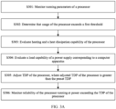
- S301 Monitor running parameters of a processor.
- a running frequency of the processor indicates a quantity of operations performed by the processor per second, where time for performing one operation each time is referred to as a periodicity of the processor. For example, when the processor runs at a frequency of 1 GHz, it means that the processor performs 1 billion operations per second, and one second includes 1 billion periodicities of the processor. To enable the processor to run stably, the processor usually does not run in a full load.
- the processor performs operations in some periodicities of the processor, and remains in an idle mode in other periodicities. In a period of time, a ratio of a quantity of periodicities in which the processor performs operations to a total quantity of periodicities in the period of time is referred to as the usage of the processor.
- Heating monitoring on the processor may be implemented by monitoring a temperature of the processor.
- the temperature of the processor usually includes a packaging case temperature Tcase of the processor and a junction temperature Tj of the processor, where the junction temperature is usually higher than the packaging case temperature.
- the packaging case temperature, or the junction temperature of the processor may be used for measurement. This is not limited in this application.
- the heat dissipation capability of the processor is usually related to a rotational speed of a fan.
- a higher rotational speed of the fan corresponding to the processor indicates a stronger heat dissipation capability, but also means a smaller margin of the heat dissipation capability.
- a ratio of revolutions per minute (revolutions per minute, RPM) of the fan to maximum revolutions per minute designed in the fan may be calculated.
- RPM revolutions per minute
- the power of the processor is determined based on a voltage applied to the processor and a current flowing through the processor.
- the processor usually includes a voltage detection apparatus, which may detect a current voltage of the processor.
- the current of the processor usually needs to be obtained from a component outside the processor.
- the computer apparatus determines, through monitoring, the power of the processor based on the detected voltage and the obtained current.
- S302 Determine that the usage of the processor exceeds a first threshold.
- a computing capability of the processor is positively correlated with the power and usage of the processor.
- the power of the processor can be adjusted to improve the computing capability of the processor.
- limitation of the TDP makes it difficult to further greatly increase the power of the processor. In this case, the usage of the processor can be increased to improve the computing capability of the processor.
- the first threshold may be a fixed value, for example, 80%, or may be separately set based on different models of processors. This is not limited in this application.
- the heating and the heat dissipation capability are evaluated from the following two aspects.
- a difference between a highest temperature that can be tolerated by the processor and a current temperature of the processor is considered.
- the highest temperature of the processor is a maximum temperature that can be tolerated by a component included in the processor without damage.
- some manufactures provide a temperature protection function during producing the processor to ensure that the processor is not damaged due to overheating, in an implementation provided in this application, to ensure that the processor is not damaged due to overheating caused by power exceeding the TDP, and is applicable to more scenarios, the difference between the highest temperature of the processor and the current temperature of the processor is first calculated before the power of the processor is increased, that is, a margin by which the current temperature of the processor can be further increased.
- the second threshold may be a preset fixed value. For example, the second threshold is set to 30 degrees Celsius. When the highest temperature of the processor is 80 degrees Celsius, and the current temperature of the processor is 40 degrees Celsius, the difference between the highest temperature of the processor and the current temperature of the processor is 40 degrees Celsius, which is greater than the second threshold. Therefore, the power of the processor can be increased.
- the second threshold may be obtained by using a specific calculation method based on to-be-increased power of the processor. For example, when it is estimated that the power of the processor is increased by 20 W, and it is obtained, by using the calculation method, that increasing the power of the processor by 20 W increases the temperature of the processor by 10 degrees Celsius, the 10 degrees Celsius is used as the second threshold.
- the case temperature (Case Temperature) of the processor or a temperature of another part can be used. This is not limited in this application.
- Heat dissipation of the computer apparatus usually includes two types: air cooling and liquid cooling.
- Air cooling indicates that air is used as a medium for cooling a to-be-cooled object.
- a fan is used to accelerate heat exchange between a heating component in the computer apparatus and surrounding air, and the fan and a component in the computer apparatus are combined to form an air duct in a chassis to enhance a heat dissipation effect.
- Water cooling indicates that liquid is driven by a pump to forcibly circulate to take away heat of a radiator, thereby reducing a temperature of a component in the computer apparatus.
- the heat dissipation capability of the computer apparatus is mainly determined by a rotational speed of a fan
- the rotational speed of the fan When the rotational speed of the fan is high, heat exchange between a heating component and surrounding air is more intense, and the heat dissipation capability is stronger.
- Each fan has its maximum revolutions per minute (revolutions per minute, RPM).
- RPM revolutions per minute
- a ratio of current RPM of the fan to maximum RPM of the fan indicates a proportion of a heat dissipation capability that has been currently used by the computer apparatus for the processor. Therefore, this ratio needs to be considered when the power of the processor is increased.
- the ratio of the current RPM of the fan to the maximum RPM of the fan is less than or equal to a third threshold, it indicates that the computer apparatus currently does not use an excessive proportion of heat dissipation capability for the processor. Even if the processor generates more heat due to power increase, the computer apparatus can increase the rotational speed of the fan to enhance the heat dissipation capability for the processor. Therefore, the power of the processor can be increased.
- the ratio of the current RPM of the fan to the maximum RPM of the fan is greater than a third threshold, it indicates that the computer apparatus currently uses an excessive proportion of the heat dissipation capability for the processor.
- the processor generates more heat due to power increase, it is difficult for the computer apparatus to further improve the heat dissipation capability for the processor. Therefore, it is inappropriate to increase the power of the processor.
- Liquid cooling is to use a pump to circulate coolant in a heat dissipation pipe and dissipate heat.
- a liquid cooling heat dissipation system usually has the following components: a liquid cooling block, circulating liquid, a pump, a pipe, and a liquid box or a heat exchanger.
- the liquid cooling block is a metal block with a channel reserved inside, and is made of copper or aluminum.
- the liquid cooling block is in contact with a heating component and absorbs heat of the heating component.
- the circulating liquid flows in the circulating pipe under an action of the water pump. Liquid that absorbs the heat of the heating component flows away from the liquid cooling block on the heating component, and new low-temperature circulating liquid continues to absorb the heat of the heating component.
- the pipe connects the pump, the liquid cooling block, and the liquid box.
- a function of the pipe is to enable the circulating liquid to circulate in the confined channel without leakage, so that the liquid cooling heat dissipation system works appropriately.
- the liquid box is used to store the circulating liquid.
- the heat exchanger is an apparatus similar to a heat sink. The circulating liquid transfers the heat to the heat sink with a large surface area, and a fan on the heat sink takes away the heat that flows into the air.
- Q is the heat dissipation capability of the liquid cooling system
- c is a specific heat capacity of liquid
- m is a mass of the liquid, and is positively correlated with a thickness of the liquid pipe and a flow rate of the liquid
- the flow rate of the liquid is positively correlated with hydraulic pressure
- dt is a temperature difference between the liquid and a heat dissipation object.
- a heat dissipation margin of the liquid cooling heat dissipation system may be obtained and determined based on a current temperature of the liquid and a difference between current hydraulic pressure of a liquid pipe and maximum hydraulic pressure of the liquid cooling heat dissipation system or a ratio of current hydraulic pressure of a liquid pipe to maximum hydraulic pressure of the liquid cooling heat dissipation system. For example, whether a margin from the hydraulic pressure of the liquid pipe to a maximum hydraulic pressure of the liquid cooling heat dissipation system exceeds a preset value or whether a margin from the current temperature of the liquid to a maximum temperature that the processor can tolerate exceeds a preset value may be determined, so as to determine whether to release the limitation on the power of the processor.
- S304 Evaluate a load capability of a power supply corresponding to the computer apparatus.
- a load capability of a power supply may be evaluated in the following several steps.
- S3041 A computer apparatus predicts an increment in power of a processor.
- the computer apparatus sends an electric energy request to a first power supply controller, where the electric energy request carries the predicted increment in power of the processor, the first power supply controller is configured to control power supply to the computer apparatus, and the predicted increment in power of the processor may be an increment in TDP of the processor.
- the first power supply controller determines, based on the electric energy request, whether the predicted increment in power of the processor can be provided.
- the first power supply controller When the first power supply controller cannot provide the increment in power of the processor, the first power supply controller sends a refusal response to the computer apparatus, where the refusal response is used to indicate that the first power supply controller refuses to allocate electric energy requested by the computer apparatus to the computer apparatus because the first power supply controller determines that the power supply cannot provide the electric energy requested by the computer apparatus.
- S305 Adjust the TDP of the processor, where adjusted TDP of the processor is greater than the preset TDP.
- the power of the processor When it is determined that the usage of the processor exceeds the first threshold, the power of the processor needs to be further increased to meet the service requirement.
- the power of the processor may exceed the preset TDP.
- the TDP is increased, so that the power of the processor can be increased to a value between the preset TDP and the increased TDP.
- original TDP is 50 W (watt, W)
- the TDP is adjusted to 60 W according to the service requirement.
- the power of the processor may increase to a value between 50 W and 60 W, so as to exceed the preset TDP.
- the TDP needs to be directly adjusted, but in the conventional technology, the TDP of processors of a same model are determined. Therefore, a TDP adjustment function may be preset during manufacturing of the processor provided in this application, and the TDP can be adjusted according to the requirement.
- the TDP adjustment function may be implemented by using a BMC or a BIOS, or in a form of software code. This is not limited in this application.
- the TDP adjusting operation may be performed automatically or performed after confirmation of a user or an administrator.
- the function is the automatic enabling function.
- the function is specifically adjusting the TDP when the power of the processor is close to the TDP.
- the function may be implemented by using a BIOS, a BMC, or software code.
- the TDP is adjusted after confirmation of the user or the administrator.
- the computer system presents an adjustment request to the user, where the adjustment request is used to indicate the user to confirm whether the TDP is allowed to be adjusted.
- the adjustment request may be presented in a plurality of methods.
- a method for setting the adjustment request is not limited in this application.
- the adjustment request may be displayed on a display in a form of a pop-up window, and the user is prompted to select "yes" or "no" according to an actual situation.
- the computer apparatus may prompt, through a voice, the user to confirm whether the TDP is allowed to be adjusted.
- the increment in TDP of the processor may be determined based on a current running parameter of the processor.
- S306 Monitor reliability of the processor running at power exceeding the preset TDP of the processor.
- Reliability of the processor is likely to be affected when the processor is running at the power exceeding the preset TDP of the processor of this type. Therefore, after the TDP is adjusted, reliability of the processor running at the current power needs to be evaluated. Reliability of the processor can be evaluated based on the junction temperature of the processor and a quantity of soft errors within a specified period of time.
- a junction temperature indicates an actual working temperature of a semiconductor in an electronic device, and is also a highest temperature of an actual semiconductor chip (a wafer or a bare die) in the electronic device. If a working temperature of the processor exceeds a maximum junction temperature, a transistor in the processor is damaged and the component is invalid.
- the junction temperature can better reflect an actual condition of the processor than a surface temperature. To prevent the processor from being burnt due to overheating, the junction temperature is more appropriate for evaluating reliability of the processor during running.
- this application sets no limitation on using the junction temperature to evaluate reliability of the processor during running. Using another temperature of the processor, including the surface temperature, to evaluate reliability of the processor during running also falls within the protection scope of this application.
- the soft error is an error caused due to an incorrect signal or incorrect data.
- the soft error can cause a change in an instruction or one piece of data in a program.
- the soft errors are usually classified into an integrated circuit-level soft error and a system-level soft error.
- the integrated circuit-level soft error is usually caused because a high-energy particle hits an integrated circuit. For example, when a radioactive atom in an integrated circuit material decays, ⁇ particles are released and hit the integrated circuit. Because the ⁇ particles have positive charges and energy, if a storage unit is hit, a value in a storage unit may change. Atomic reaction in the foregoing example is very small and does not affect a hardware structure of the integrated circuit.
- the system-level soft error occurs when to-be-processed data is affected by noise or when the data is on a bus.
- a computer interprets the noise as data bits.
- program addressing or code processing errors occur.
- the actual power of the processor exceeds the preset TDP, if the quantity of the soft errors generated within the specified period of time exceeds a fourth threshold, an alarm needs to be sent or the TDP of the processor needs to be directly reduced, so as to reduce the power of the processor.
- the processor is allowed to run, in a short time, at the power higher than the preset TDP, is to meet the burst high computing performance requirement. If the processor runs in a high power mode for a long time, reliability of the computer system is affected, and a loss of the processor is accelerated.
- the computer apparatus can monitor duration in which the processor runs at the power exceeding the preset TDP, or monitor a proportion of duration in which the processor runs at the power exceeding the preset TDP to entire working duration. If the working duration or the proportion exceeds a preset threshold, the alarm is sent to notify the user to use a processor with higher performance in time, so as to prevent the processor from working at the power exceeding the preset TDP for a long time.
- FIG. 5 is a schematic flowchart of another embodiment according to this application.
- S501 Monitor running parameters of a processor.
- S502 Determine that usage of the processor exceeds a first threshold.
- S504 Evaluate a load capability of a power supply corresponding to a computer apparatus.
- steps S501, S502, S503, and S504 in FIG. 3A Details are not described herein again.
- S505 Adjust a current of the processor obtained through monitoring, where an adjusted current of the processor obtained through monitoring is less than the current of the processor.
- the method for adjusting the TDP is already provided in FIG. 3A , and this embodiment provides another method. Because the processor obtains, through monitoring, the power of the processor based on voltage of the processor and the current obtained through monitoring, if the current of the processor obtained through monitoring is less than an actual current, the monitored power of the processor is also less than the current actual power of the processor, so that maximum power of the processor can actually be increased, thereby exceeding the preset TDP.
- a processor and a second power supply controller are connected through a bus, and the second power supply controller is configured to control power supply to the processor.
- the bus may be an inter-integrated circuit (Inter-Integrated Circuit, I 2 C or I2C) bus, or may be another type of bus. This is not limited in this application.
- the processor may obtain the current voltage of the processor, and obtain the current obtained from the second power supply controller through monitoring.
- the processor may obtain, through monitoring, the current power of the processor based on the current voltage and the current monitored current.
- a processor manufacturer usually installs a power protection function for the processor. When the processor detects that the current monitored power is equal to or close to the TDP, the processor reduces a frequency of the processor.
- the voltage of the processor is positively correlated to the frequency of the processor. When the frequency of the processor is reduced, the voltage of the processor is also reduced, thereby reducing the power of the processor.
- triggering of the power protection function of the processor may be avoided by enabling the monitored power of the processor to be less than the actual power of the processor.
- the processor may obtain the voltage of the processor, but the computer apparatus cannot change the voltage. However, the computer apparatus may change, by using a method such as changing a parameter stored in a register of the second power supply controller, the current obtained by the processor.
- the computer apparatus when the computer apparatus needs to adjust the power of the processor to enable the power of the processor to exceed the preset TDP, the computer apparatus can modify the parameter in the register of the second power supply controller, so that the current monitored power detected by the processor is less than the current actual power of the processor, and the actual power of the processor can exceed the preset TDP when the monitored power detected by the processor is less than the preset TDP.
- the monitored current adjusted by the processor may also be determined based on parameters such as a current temperature of the processor and a current rotational speed of a fan.
- S506 Monitor reliability of the processor running at power exceeding the preset TDP of the processor.
- step S306 when too many errors occur or running duration is excessively long when the processor runs at the power exceeding the TDP preset in the processor, an alarm is sent, or the current obtained by the processor through monitoring is increased, thereby reducing the power of the processor.
- FIG. 6 is a schematic diagram of function modules in a computer apparatus configured to adjust power of a processor according to an embodiment of this application.
- the computer apparatus 600 includes a processing module 610, a monitor module 620, and an adjustment module 630.
- the monitor module 620 is configured to determine that usage of the processing module 610 exceeds a first threshold.
- the adjustment module 630 is configured to adjust TDP of the processing module 610, where adjusted TDP of the processing module 610 is greater than the preset TDP of the processing module 610.
- the computer apparatus 600 is further configured to perform other steps, of adjusting the power of the processor, shown in FIG. 3A , FIG. 3B , and FIG. 5 .
- the monitor module 620 is configured to perform step S301, step S302, step S303, step S304, and step S306 in FIG. 3A , step 3041 and step 3042 in FIG. 3B , and step S501, step S502, step S503, step S504, and step S506 in FIG. 5 .
- the adjustment module 630 is configured to perform steps such as step S305 in FIG. 3A and step S505 in FIG. 5 .
- each module performs each step refer to the foregoing descriptions of FIG. 3A , FIG. 3B , and FIG. 5 . Details are not described herein again.
- FIG. 7 is a schematic diagram of a structure of a computer apparatus 700 configured to adjust power of a processor according to an embodiment of this application.
- the computer apparatus 700 in this embodiment may be one specific implementation of the computer apparatuses in the foregoing embodiments.
- the computer apparatus 700 includes a processor 701, and the processor 701 is connected to a storage 705.
- the processor 701 may be computational logic such as a field programmable gate array (English full name: Field Programmable Gate Array, FPGA for short), a digital signal processor (English full name: Digital Signal Processor, DSP for short), or a combination of any computational logic.
- the processor 701 may be a single-core processor or a multi-core processor.
- the storage 705 may be a random access memory (Random Access Memory, RAM), a flash memory, a read-only memory (Read-Only Memory, ROM), an erasable programmable read-only memory (Erasable Programmable Read-Only Memory, EPROM), an electrically erasable programmable read-only memory (Electrically Erasable Programmable read-only memory, EEPROM), a register, or any other form of storage medium known in the art.
- the storage may be configured to store program instructions. When the program instructions are executed by the processor 701, the processor 701 performs the method in the foregoing embodiment.
- connection line 709 is used for transferring information between components of the computer apparatus.
- the connection line 709 may be connected in a wired connection manner or a wireless connection manner. This is not limited in this application.
- the connection 709 is further connected to a communications interface 704.
- the communications interface 704 implements communication with another device or a network 711 by using, for example but not limited to, a connection apparatus such as a cable or an electrical twisted wire.
- the communications interface 704 may also be interconnected with the network 711 in a wireless manner.
- Some features in this embodiment of this application may be implemented/supported by the processor 701 by executing the program instructions or software code in the storage 705.
- Software components loaded on the storage 705 may be summarized in terms of function or logic, for example, the monitor module 620 and the adjustment module 630 shown in FIG. 6 .
- the processor 701 executes a transaction related to the foregoing function/logical module in the storage.
- FIG. 7 shows merely an example of the computer apparatus 700.
- the computer apparatus 700 may include more or fewer components than those shown in FIG. 7 , or may have different component arrangements.
- various components shown in FIG. 7 may be implemented by using hardware, software, or a combination of hardware and software.
- the storage and the processor may be implemented in one module. Instructions in the storage may be written into the storage in advance, or may be loaded in a subsequent execution process of the processor.
- FIG. 8 is a schematic diagram of a structure of a processor 800 configured to adjust power of the processor according to an embodiment of this application.
- the processor 800 includes a core (Core) 810, a memory controller (Memory Controller, MC) 820, a cache (Cache) 830, and a monitor module 840.
- the core 810 is a computing unit inside the processor, is a core component of the processor, and is responsible for providing computing power for the processor.
- the MC 820 is responsible for interaction between the processor and the memory.
- the MC 820 is a bus circuit controller configured to manage and plan a transmission speed from the memory to the processor.
- the MC 820 may be an independent chip, or may be integrated into a related large chip.
- the cache 830 is a component configured to reduce average time required by the processor to gain access to the memory. A capacity of the cache 830 is far less than a capacity of the memory, but a speed may be close to a frequency of the processor.
- the processor 800 further includes a monitor module 840.
- the monitor module 840 may monitor parameters of the processor 800, for example, a frequency, a voltage, and a temperature of the core, and may obtain a current of the processor 800 from a second power supply controller connected to the processor.
- the monitor module 840 may obtain the power of the processor 800 based on the voltage of the processor and the obtained current.
- the monitor module 840 sends instructions to the core 810, to reduce the power of the processor 800 by reducing the frequency of the core.
- the core 810 may load the instructions in the memory or the cache 830 to execute the instructions and invoke the monitor module 840 to execute the procedures in FIG. 3A , FIG. 3B , and FIG. 5 of this application.
- the monitor module 840 may determine that usage of the processor exceeds a first threshold, and the core may be configured to adjust thermal design power of the processor.
- the monitor module 840 may be an independent component.
- the monitor module 840 may be minimum instruction set computer input/output (minimal instruction set computer input/output, MISC I/O).
- the apparatus is an I/O bus interface around the processor, and may have a built-in sensor to monitor the voltage of the processor and obtain the current of the processor through the bus.
- the monitor module 840 may also be integrated into another component.
- the monitor module 840 may be integrated into the core 810. This is not limited in this application.
Landscapes
- Engineering & Computer Science (AREA)
- Theoretical Computer Science (AREA)
- Physics & Mathematics (AREA)
- General Engineering & Computer Science (AREA)
- General Physics & Mathematics (AREA)
- Quality & Reliability (AREA)
- Computing Systems (AREA)
- Mathematical Physics (AREA)
- Computer Hardware Design (AREA)
- Human Computer Interaction (AREA)
- Power Sources (AREA)
Claims (16)
- Verfahren zum Einstellen einer Leistung eines Prozessors, wobei das Verfahren in einem Computergerät verwendet wird, das Computergerät den Prozessor umfasst und das Verfahren Folgendes umfasst:Bestimmen, dass Nutzung des Prozessors einen ersten Schwellenwert überschreitet; undwenn die Nutzung des Prozessors den ersten Schwellenwert überschreitet, Anpassen einer Thermal Design Power, TDP, des Prozessors, wobei die angepasste TDP des Prozessors größer als die voreingestellte TDP des Prozessors ist;wobei das Verfahren nach dem Anpassen der TDP des Prozessors ferner Folgendes umfasst:Überwachen einer Anzahl von Fehlern, die innerhalb eines spezifizierten Zeitraums in dem Prozessor auftreten; undReduzieren der TDP des Prozessors, wenn die Anzahl von Fehlern, die innerhalb des spezifizierten Zeitraums in dem Prozessor auftreten, größer oder gleich einem vierten Schwellenwert ist.
- Verfahren nach Anspruch 1, wobei das Verfahren vor dem Anpassen der TDP des Prozessors ferner Folgendes umfasst:Erlangen einer aktuellen Temperatur des Prozessors; undBestimmen, dass eine Differenz zwischen einer höchsten Temperatur des Prozessors und der aktuellen Temperatur des Prozessors größer oder gleich einem zweiten Schwellenwert ist, sodass die Leistung des Prozessors in diesem Falle immer noch erhöht werden kann.
- Verfahren nach Anspruch 2, wobei das Verfahren vor dem Anpassen der TDP des Prozessors ferner Folgendes umfasst:Erlangen einer aktuellen Drehzahl eines Lüfters, wobei der Lüfter dazu konfiguriert ist, Wärme für den Prozessor abzuleiten; undBestimmen, dass ein Verhältnis der aktuellen Drehzahl des Lüfters zu einer maximalen Drehzahl des Lüfters kleiner oder gleich einem dritten Schwellenwert ist, sodass die Leistung des Prozessors in diesem Falle immer noch erhöht werden kann.
- Verfahren nach einem der Ansprüche 1 bis 3, wobei das Verfahren vor dem Anpassen der TDP des Prozessors ferner Folgendes umfasst:Bestimmen einer Zunahme der TDP des Prozessors;Senden einer Anforderung elektrischer Energie an eine Leistungsversorgungssteuerung, wobei die Anforderung elektrischer Energie Informationen über die Zunahme der TDP des Prozessors enthält; undEmpfangen einer Reaktion, die durch die Leistungsversorgungssteuerung gesandt wird, wobei die Reaktion dazu verwendet wird, anzuzeigen, dass die Leistungsversorgungssteuerung dem Computergerät elektrische Energie entsprechend der Zunahme der TDP des Prozessors zugewiesen hat.
- Verfahren nach einem der Ansprüche 1 bis 4, wobei das Verfahren nach dem Anpassen der TDP des Prozessors ferner Folgendes umfasst:Überwachen einer Dauer, während welcher der Prozessor mit einer Leistung läuft, welche die voreingestellte TDP überschreitet; undSenden eines Alarms, wenn die Dauer, während welcher der Prozessor mit der Leistung läuft, welche die voreingestellte TDP überschreitet, einen fünften Schwellenwert überschreitet.
- Verfahren nach Anspruch 3, wobei das Anpassen der TDP des Prozessors Folgendes umfasst:
Bestimmen der angepassten TDP des Prozessors basierend auf der Differenz zwischen der höchsten Temperatur des Prozessors und der aktuellen Temperatur des Prozessors und dem Verhältnis der aktuellen Drehzahl des Lüfters zu der maximalen Drehzahl des Lüfters. - Verfahren nach einem der Ansprüche 1 bis 6, wobei das Anpassen der TDP des Prozessors Folgendes umfasst:
Anpassen der TDP des Prozessors unter Verwendung eines Basic Input/Output System, BIOS, oder einer Basisbandverwaltungssteuerung, BMC, in dem Computergerät. - Computergerät, wobei das Computergerät Folgendes umfasst:ein Verarbeitungsmodul;ein Überwachungsmodul, das dazu konfiguriert ist, zu bestimmen, dass Nutzung des Verarbeitungsmoduls einen ersten Schwellenwert überschreitet; undein Anpassungsmodul, das dazu konfiguriert ist, eine Thermal Design Power, TDP, des Verarbeitungsmoduls anzupassen, wenn die Nutzung des Verarbeitungsmoduls den ersten Schwellenwert überschreitet, wobei die angepasste TDP des Verarbeitungsmoduls größer als die voreingestellte TDP des Verarbeitungsmoduls ist; wobei das Überwachungsmodul ferner zu Folgendem konfiguriert ist: Überwachen einer Anzahl von Fehlern, die innerhalb eines spezifizierten Zeitraums in dem Verarbeitungsmodul auftreten, nachdem das Anpassungsmodul die TDP des Verarbeitungsmoduls anpasst; unddas Anpassungsmodul ferner zu Folgendem konfiguriert ist:
Reduzieren der TDP des Verarbeitungsmoduls, wenn die Anzahl von Fehlern, die innerhalb des spezifizierten Zeitraums in dem Verarbeitungsmodul auftreten, größer oder gleich einem vierten Schwellenwert ist. - Computergerät nach Anspruch 8, wobei
das Überwachungsmodul ferner zu Folgendem konfiguriert ist:Erlangen einer aktuellen Temperatur des Verarbeitungsmoduls, bevor das Anpassungsmodul die TDP des Verarbeitungsmoduls anpasst; undBestimmen, dass eine Differenz zwischen einer höchsten Temperatur des Verarbeitungsmoduls und der aktuellen Temperatur des Verarbeitungsmoduls größer oder gleich einem zweiten Schwellenwert ist. - Computergerät nach Anspruch 9, wobei
das Überwachungsmodul ferner zu Folgendem konfiguriert ist:Erlangen einer aktuellen Drehzahl eines Lüfters, bevor das Anpassungsmodul die TDP des Verarbeitungsmoduls anpasst, wobei der Lüfter dazu konfiguriert ist, Wärme für das Verarbeitungsmodul abzuleiten; undBestimmen, dass ein Verhältnis der aktuellen Drehzahl des Lüfters zu einer maximalen Drehzahl des Lüfters kleiner oder gleich einem dritten Schwellenwert ist. - Computergerät nach einem der Ansprüche 8 bis 10, wobei das Überwachungsmodul ferner zu Folgendem konfiguriert ist:Bestimmen einer Zunahme der TDP des Verarbeitungsmoduls, bevor das Anpassungsmodul die TDP des Verarbeitungsmoduls anpasst;Senden einer Anforderung elektrischer Energie an eine Leistungsversorgungssteuerung, wobei die Anforderung elektrischer Energie Informationen über die Zunahme der TDP des Verarbeitungsmoduls enthält; undEmpfangen einer Reaktion, die durch die Leistungsversorgungssteuerung gesandt wird, wobei die Reaktion dazu verwendet wird, anzuzeigen, dass die Leistungsversorgungssteuerung dem Computergerät elektrische Energie entsprechend der Zunahme der TDP des Verarbeitungsmoduls zugewiesen hat.
- Computergerät nach einem der Ansprüche 8 bis 11, wobei das Überwachungsmodul ferner zu Folgendem konfiguriert ist:nachdem das Anpassungsmodul die TDP des Verarbeitungsmoduls anpasst, Überwachen einer Dauer, während der das Verarbeitungsmodul mit einer Leistung läuft, welche die voreingestellte TDP überschreitet; undSenden eines Alarms, wenn die Dauer, während der das Verarbeitungsmodul mit der Leistung läuft, welche die voreingestellte TDP überschreitet, einen fünften Schwellenwert überschreitet.
- Computergerät nach Anspruch 10, wobei
das Überwachungsmodul dazu konfiguriert ist, die angepasste TDP des Verarbeitungsmoduls basierend auf der Differenz zwischen der höchsten Temperatur des Verarbeitungsmoduls und der aktuellen Temperatur des Verarbeitungsmoduls und dem Verhältnis der aktuellen Drehzahl des Lüfters zu der maximalen Drehzahl des Lüfters zu bestimmen. - Computergerät nach einem der Ansprüche 8 bis 13, wobei
das Anpassungsmodul dazu konfiguriert ist, die TDP des Verarbeitungsmoduls unter Verwendung eines Basic Input/Output System, BIOS, oder einer Basisbandverwaltungssteuerung, BMC, in dem Computergerät anzupassen. - Computergerät, wobei das Computergerät einen Speicher und einen Prozessor umfasst, der Speicher dazu konfiguriert ist, Programmcode zu speichern, und der Prozessor dazu konfiguriert ist, den Programmcode in dem Speicher abzurufen, um das Verfahren nach einem der Ansprüche 1 bis 7 durchführen.
- Prozessor, wobei der Prozessor ein Überwachungsmodul und einen Kern umfasst unddas Überwachungsmodul dazu konfiguriert ist, zu bestimmen, dass Nutzung des Prozessors einen ersten Schwellenwert überschreitet;
undder Kern dazu konfiguriert ist, eine Thermal Design Power, TDP, des Prozessors anzupassen, wenn die Nutzung des Prozessors den ersten Schwellenwert überschreitet, wobei die angepasste TDP des Prozessors größer als die voreingestellte TDP des Prozessors ist:wobei das Überwachungsmodul ferner zu Folgendem konfiguriert ist: Überwachen einer Anzahl von Fehlern, die innerhalb eines spezifizierten Zeitraums in dem Verarbeitungsmodul auftreten, nachdem das Anpassungsmodul die TDP des Verarbeitungsmoduls anpasst; undder Kern ferner zu Folgendem konfiguriert ist: Reduzieren der TDP des Prozessors, wenn die Anzahl von Fehlern, die innerhalb des spezifizierten Zeitraums in dem Prozessor auftreten, größer oder gleich einem vierten Schwellenwert ist.
Applications Claiming Priority (3)
| Application Number | Priority Date | Filing Date | Title |
|---|---|---|---|
| CN201911328960 | 2019-12-20 | ||
| CN201911424047.XA CN113009999B (zh) | 2019-12-20 | 2019-12-31 | 一种处理器的功率调整方法及装置 |
| PCT/CN2020/113280 WO2021120700A1 (zh) | 2019-12-20 | 2020-09-03 | 一种处理器的功率调整方法及装置 |
Publications (3)
| Publication Number | Publication Date |
|---|---|
| EP4064003A1 EP4064003A1 (de) | 2022-09-28 |
| EP4064003A4 EP4064003A4 (de) | 2023-01-18 |
| EP4064003B1 true EP4064003B1 (de) | 2024-11-06 |
Family
ID=76383410
Family Applications (1)
| Application Number | Title | Priority Date | Filing Date |
|---|---|---|---|
| EP20900963.8A Active EP4064003B1 (de) | 2019-12-20 | 2020-09-03 | Leistungseinstellungsverfahren und -gerät für prozessor |
Country Status (4)
| Country | Link |
|---|---|
| US (1) | US12093115B2 (de) |
| EP (1) | EP4064003B1 (de) |
| CN (1) | CN113009999B (de) |
| WO (1) | WO2021120700A1 (de) |
Families Citing this family (11)
| Publication number | Priority date | Publication date | Assignee | Title |
|---|---|---|---|---|
| US12422906B2 (en) * | 2021-02-25 | 2025-09-23 | Dell Products L.P. | Automated thermal property assignment based on surrounding part substrate |
| CN113900912B (zh) * | 2021-12-10 | 2022-04-05 | 飞腾信息技术有限公司 | 测试方法、测试装置、计算机设备及计算机可读存储介质 |
| CN116521355A (zh) * | 2022-01-30 | 2023-08-01 | 台达电子企业管理(上海)有限公司 | 提升处理器峰值算力的方法、用于提升处理器峰值算力的系统 |
| CN116700467B (zh) * | 2022-02-24 | 2026-04-14 | Oppo广东移动通信有限公司 | 调整处理器功率的方法及装置、电子设备、存储介质 |
| CN117148941A (zh) * | 2022-05-24 | 2023-12-01 | 华为技术有限公司 | 计算机系统的供电方法及相关装置和设备 |
| US12124308B2 (en) * | 2022-06-23 | 2024-10-22 | Nvidia Corporation | Techniques to modify processor performance |
| CN118394601A (zh) * | 2022-10-26 | 2024-07-26 | 荣耀终端有限公司 | 一种参数监控方法及电子设备 |
| TWI866499B (zh) * | 2023-09-27 | 2024-12-11 | 緯創資通股份有限公司 | 動態調整散熱設計功率之方法、系統及非暫時性電腦可讀儲存媒體 |
| US20250355580A1 (en) * | 2024-05-16 | 2025-11-20 | Micron Technology, Inc. | Power negotiation for memory systems |
| CN118915890B (zh) * | 2024-08-30 | 2025-05-23 | 安福得鑫智能设备有限公司 | 一种基于数据分析的智能监测管理系统 |
| CN120743028B (zh) * | 2025-09-05 | 2026-01-27 | 闽西职业技术学院 | 一种电气设备的电压控制方法及系统 |
Family Cites Families (25)
| Publication number | Priority date | Publication date | Assignee | Title |
|---|---|---|---|---|
| CN100461117C (zh) * | 2005-12-07 | 2009-02-11 | 微星科技股份有限公司 | 可调整工作频率的硬件元件的效能最佳化方法 |
| US8707060B2 (en) * | 2008-10-31 | 2014-04-22 | Intel Corporation | Deterministic management of dynamic thermal response of processors |
| JP5288120B2 (ja) | 2009-02-18 | 2013-09-11 | 国立大学法人九州大学 | ガスセンサ及びガス検出装置 |
| US8826048B2 (en) * | 2009-09-01 | 2014-09-02 | Nvidia Corporation | Regulating power within a shared budget |
| US8621246B2 (en) * | 2009-12-23 | 2013-12-31 | Intel Corporation | Power management system and method to provide supply voltage to a load |
| US8429441B2 (en) * | 2010-04-19 | 2013-04-23 | International Business Machines Corporation | Operating processor below maximum turbo mode frequency by sending higher than actual current amount signal to monitor |
| US8510582B2 (en) * | 2010-07-21 | 2013-08-13 | Advanced Micro Devices, Inc. | Managing current and power in a computing system |
| JP5345990B2 (ja) * | 2010-08-27 | 2013-11-20 | レノボ・シンガポール・プライベート・リミテッド | 特定のプロセスを短時間で処理する方法およびコンピュータ |
| US8984305B2 (en) * | 2010-12-21 | 2015-03-17 | Intel Corporation | Method and apparatus to configure thermal design power in a microprocessor |
| US8793515B2 (en) * | 2011-06-27 | 2014-07-29 | Intel Corporation | Increasing power efficiency of turbo mode operation in a processor |
| US20130173946A1 (en) * | 2011-12-29 | 2013-07-04 | Efraim Rotem | Controlling power consumption through multiple power limits over multiple time intervals |
| WO2013147849A1 (en) * | 2012-03-30 | 2013-10-03 | Intel Corporation | Dynamically measuring power consumption in a processor |
| US8793518B2 (en) * | 2012-06-13 | 2014-07-29 | Dell Products Lp | Systems and methods for providing supplemental power to battery powered information handling systems |
| US9098277B2 (en) * | 2012-08-30 | 2015-08-04 | Dell Products L.P. | Information handling system configuration for power system output capability |
| JP2014120072A (ja) * | 2012-12-18 | 2014-06-30 | Toshiba Corp | 情報処理装置および情報処理装置の制御方法 |
| US9405345B2 (en) * | 2013-09-27 | 2016-08-02 | Intel Corporation | Constraining processor operation based on power envelope information |
| US9652019B2 (en) * | 2014-06-02 | 2017-05-16 | Advanced Micro Devices, Inc. | System and method for adjusting processor performance based on platform and ambient thermal conditions |
| US20160147280A1 (en) * | 2014-11-26 | 2016-05-26 | Tessil Thomas | Controlling average power limits of a processor |
| US20160266629A1 (en) * | 2015-03-09 | 2016-09-15 | Advanced Micro Devices, Inc. | Changing power limits based on device state |
| CN105262155B (zh) * | 2015-09-02 | 2018-07-06 | 广东欧珀移动通信有限公司 | 一种充电方法及装置 |
| US9990024B2 (en) * | 2015-09-09 | 2018-06-05 | Qualcomm Incorporated | Circuits and methods providing voltage adjustment as processor cores become active based on an observed number of ring oscillator clock ticks |
| US10635146B2 (en) * | 2016-01-28 | 2020-04-28 | Dell Products, L.P. | Power monitoring calibration to a target performance level |
| CN105843571A (zh) * | 2016-03-18 | 2016-08-10 | 联想(北京)有限公司 | 一种信息处理方法和电子设备 |
| US10229027B2 (en) * | 2016-04-15 | 2019-03-12 | Dell Products L.P. | Voltage regulator power reporting offset system |
| TWI679439B (zh) * | 2018-10-01 | 2019-12-11 | 緯穎科技服務股份有限公司 | 電源管理系統及電源管理方法 |
-
2019
- 2019-12-31 CN CN201911424047.XA patent/CN113009999B/zh active Active
-
2020
- 2020-09-03 WO PCT/CN2020/113280 patent/WO2021120700A1/zh not_active Ceased
- 2020-09-03 EP EP20900963.8A patent/EP4064003B1/de active Active
-
2022
- 2022-06-17 US US17/843,414 patent/US12093115B2/en active Active
Also Published As
| Publication number | Publication date |
|---|---|
| US12093115B2 (en) | 2024-09-17 |
| EP4064003A1 (de) | 2022-09-28 |
| WO2021120700A1 (zh) | 2021-06-24 |
| CN113009999A (zh) | 2021-06-22 |
| US20220326759A1 (en) | 2022-10-13 |
| EP4064003A4 (de) | 2023-01-18 |
| CN113009999B (zh) | 2024-11-29 |
Similar Documents
| Publication | Publication Date | Title |
|---|---|---|
| EP4064003B1 (de) | Leistungseinstellungsverfahren und -gerät für prozessor | |
| US11579676B2 (en) | Systems, apparatus, and methods for controlling power consumption in an information handling device | |
| USRE47658E1 (en) | Heat dissipation system for computers | |
| US10459733B2 (en) | Power budgeting in an information handling system | |
| KR101534450B1 (ko) | 누설 전류 측정으로부터 열 관리 폴리시를 결정하는 시스템 및 방법 | |
| US9740645B2 (en) | Reducing latency in a peripheral component interconnect express link | |
| US20030088799A1 (en) | Method and apparatus for regulation of electrical component temperature and power consumption rate through bus width reconfiguration | |
| US10373283B2 (en) | System and method for normalization of GPU workloads based on real-time GPU data | |
| CN108803860A (zh) | 一种功耗调节方法及电子设备 | |
| KR101707096B1 (ko) | 일반 호스트 기반 제어기 레이턴시 방법 및 장치 | |
| US11847009B1 (en) | Power control for improving foreground application performance in an information handling system | |
| JP2022162457A (ja) | 情報処理装置および制御方法 | |
| US8304698B1 (en) | Thermal throttling of peripheral components in a processing device | |
| CN115977985A (zh) | 风扇控制方法、装置、电子设备及存储介质 | |
| CN116954332A (zh) | 电子芯片散热控制方法、装置、设备及存储介质 | |
| CN111615298A (zh) | 散热方法、装置 | |
| CN118051406A (zh) | 一种服务器的温度控制方法、系统、设备及存储介质 | |
| US7664977B2 (en) | System and method for cooling a CPU passively | |
| WO2021021191A1 (en) | Power level of central processing units at run time | |
| CN115629659A (zh) | 一种硬盘的温度调控方法及计算设备 | |
| CN117590923B (zh) | 基于i/o访问降低功耗的方法、装置及设备 | |
| US12526955B2 (en) | Monitoring closed loop liquid air assisted cooling module performance in real time | |
| CN116382438A (zh) | 一种处理器过温保护方法、相关设备及可读存储介质 | |
| WO2024006019A1 (en) | Platform efficiency tracker | |
| CN114364231A (zh) | 一种水冷系统及控制方法 |
Legal Events
| Date | Code | Title | Description |
|---|---|---|---|
| STAA | Information on the status of an ep patent application or granted ep patent |
Free format text: STATUS: THE INTERNATIONAL PUBLICATION HAS BEEN MADE |
|
| PUAI | Public reference made under article 153(3) epc to a published international application that has entered the european phase |
Free format text: ORIGINAL CODE: 0009012 |
|
| STAA | Information on the status of an ep patent application or granted ep patent |
Free format text: STATUS: REQUEST FOR EXAMINATION WAS MADE |
|
| 17P | Request for examination filed |
Effective date: 20220620 |
|
| AK | Designated contracting states |
Kind code of ref document: A1 Designated state(s): AL AT BE BG CH CY CZ DE DK EE ES FI FR GB GR HR HU IE IS IT LI LT LU LV MC MK MT NL NO PL PT RO RS SE SI SK SM TR |
|
| REG | Reference to a national code |
Ref country code: DE Ref legal event code: R079 Free format text: PREVIOUS MAIN CLASS: G06F0001320600 Ipc: G06F0001200000 Ref country code: DE Ref legal event code: R079 Ref document number: 602020041081 Country of ref document: DE Free format text: PREVIOUS MAIN CLASS: G06F0001320600 Ipc: G06F0001200000 |
|
| A4 | Supplementary search report drawn up and despatched |
Effective date: 20221221 |
|
| RIC1 | Information provided on ipc code assigned before grant |
Ipc: G06F 11/30 20060101ALI20221215BHEP Ipc: G06F 1/3296 20190101ALI20221215BHEP Ipc: G06F 1/324 20190101ALI20221215BHEP Ipc: G06F 1/3234 20190101ALI20221215BHEP Ipc: G06F 1/3206 20190101ALI20221215BHEP Ipc: G06F 1/28 20060101ALI20221215BHEP Ipc: G06F 1/20 20060101AFI20221215BHEP |
|
| DAV | Request for validation of the european patent (deleted) | ||
| DAX | Request for extension of the european patent (deleted) | ||
| GRAP | Despatch of communication of intention to grant a patent |
Free format text: ORIGINAL CODE: EPIDOSNIGR1 |
|
| STAA | Information on the status of an ep patent application or granted ep patent |
Free format text: STATUS: GRANT OF PATENT IS INTENDED |
|
| RIC1 | Information provided on ipc code assigned before grant |
Ipc: G06F 11/34 20060101ALI20240418BHEP Ipc: G06F 11/30 20060101ALI20240418BHEP Ipc: G06F 1/3296 20190101ALI20240418BHEP Ipc: G06F 1/324 20190101ALI20240418BHEP Ipc: G06F 1/3234 20190101ALI20240418BHEP Ipc: G06F 1/3206 20190101ALI20240418BHEP Ipc: G06F 1/28 20060101ALI20240418BHEP Ipc: G06F 1/20 20060101AFI20240418BHEP |
|
| INTG | Intention to grant announced |
Effective date: 20240510 |
|
| GRAS | Grant fee paid |
Free format text: ORIGINAL CODE: EPIDOSNIGR3 |
|
| GRAA | (expected) grant |
Free format text: ORIGINAL CODE: 0009210 |
|
| STAA | Information on the status of an ep patent application or granted ep patent |
Free format text: STATUS: THE PATENT HAS BEEN GRANTED |
|
| AK | Designated contracting states |
Kind code of ref document: B1 Designated state(s): AL AT BE BG CH CY CZ DE DK EE ES FI FR GB GR HR HU IE IS IT LI LT LU LV MC MK MT NL NO PL PT RO RS SE SI SK SM TR |
|
| REG | Reference to a national code |
Ref country code: GB Ref legal event code: FG4D |
|
| REG | Reference to a national code |
Ref country code: CH Ref legal event code: EP |
|
| REG | Reference to a national code |
Ref country code: DE Ref legal event code: R096 Ref document number: 602020041081 Country of ref document: DE |
|
| REG | Reference to a national code |
Ref country code: IE Ref legal event code: FG4D |
|
| REG | Reference to a national code |
Ref country code: LT Ref legal event code: MG9D |
|
| REG | Reference to a national code |
Ref country code: NL Ref legal event code: MP Effective date: 20241106 |
|
| PG25 | Lapsed in a contracting state [announced via postgrant information from national office to epo] |
Ref country code: IS Free format text: LAPSE BECAUSE OF FAILURE TO SUBMIT A TRANSLATION OF THE DESCRIPTION OR TO PAY THE FEE WITHIN THE PRESCRIBED TIME-LIMIT Effective date: 20250306 Ref country code: PT Free format text: LAPSE BECAUSE OF FAILURE TO SUBMIT A TRANSLATION OF THE DESCRIPTION OR TO PAY THE FEE WITHIN THE PRESCRIBED TIME-LIMIT Effective date: 20250306 Ref country code: HR Free format text: LAPSE BECAUSE OF FAILURE TO SUBMIT A TRANSLATION OF THE DESCRIPTION OR TO PAY THE FEE WITHIN THE PRESCRIBED TIME-LIMIT Effective date: 20241106 |
|
| PG25 | Lapsed in a contracting state [announced via postgrant information from national office to epo] |
Ref country code: FI Free format text: LAPSE BECAUSE OF FAILURE TO SUBMIT A TRANSLATION OF THE DESCRIPTION OR TO PAY THE FEE WITHIN THE PRESCRIBED TIME-LIMIT Effective date: 20241106 Ref country code: NL Free format text: LAPSE BECAUSE OF FAILURE TO SUBMIT A TRANSLATION OF THE DESCRIPTION OR TO PAY THE FEE WITHIN THE PRESCRIBED TIME-LIMIT Effective date: 20241106 |
|
| REG | Reference to a national code |
Ref country code: AT Ref legal event code: MK05 Ref document number: 1740066 Country of ref document: AT Kind code of ref document: T Effective date: 20241106 |
|
| PG25 | Lapsed in a contracting state [announced via postgrant information from national office to epo] |
Ref country code: BG Free format text: LAPSE BECAUSE OF FAILURE TO SUBMIT A TRANSLATION OF THE DESCRIPTION OR TO PAY THE FEE WITHIN THE PRESCRIBED TIME-LIMIT Effective date: 20241106 |
|
| PG25 | Lapsed in a contracting state [announced via postgrant information from national office to epo] |
Ref country code: ES Free format text: LAPSE BECAUSE OF FAILURE TO SUBMIT A TRANSLATION OF THE DESCRIPTION OR TO PAY THE FEE WITHIN THE PRESCRIBED TIME-LIMIT Effective date: 20241106 |
|
| PG25 | Lapsed in a contracting state [announced via postgrant information from national office to epo] |
Ref country code: NO Free format text: LAPSE BECAUSE OF FAILURE TO SUBMIT A TRANSLATION OF THE DESCRIPTION OR TO PAY THE FEE WITHIN THE PRESCRIBED TIME-LIMIT Effective date: 20250206 |
|
| PG25 | Lapsed in a contracting state [announced via postgrant information from national office to epo] |
Ref country code: LV Free format text: LAPSE BECAUSE OF FAILURE TO SUBMIT A TRANSLATION OF THE DESCRIPTION OR TO PAY THE FEE WITHIN THE PRESCRIBED TIME-LIMIT Effective date: 20241106 Ref country code: GR Free format text: LAPSE BECAUSE OF FAILURE TO SUBMIT A TRANSLATION OF THE DESCRIPTION OR TO PAY THE FEE WITHIN THE PRESCRIBED TIME-LIMIT Effective date: 20250207 Ref country code: AT Free format text: LAPSE BECAUSE OF FAILURE TO SUBMIT A TRANSLATION OF THE DESCRIPTION OR TO PAY THE FEE WITHIN THE PRESCRIBED TIME-LIMIT Effective date: 20241106 |
|
| PG25 | Lapsed in a contracting state [announced via postgrant information from national office to epo] |
Ref country code: PL Free format text: LAPSE BECAUSE OF FAILURE TO SUBMIT A TRANSLATION OF THE DESCRIPTION OR TO PAY THE FEE WITHIN THE PRESCRIBED TIME-LIMIT Effective date: 20241106 |
|
| PG25 | Lapsed in a contracting state [announced via postgrant information from national office to epo] |
Ref country code: RS Free format text: LAPSE BECAUSE OF FAILURE TO SUBMIT A TRANSLATION OF THE DESCRIPTION OR TO PAY THE FEE WITHIN THE PRESCRIBED TIME-LIMIT Effective date: 20250206 |
|
| PG25 | Lapsed in a contracting state [announced via postgrant information from national office to epo] |
Ref country code: SM Free format text: LAPSE BECAUSE OF FAILURE TO SUBMIT A TRANSLATION OF THE DESCRIPTION OR TO PAY THE FEE WITHIN THE PRESCRIBED TIME-LIMIT Effective date: 20241106 |
|
| PG25 | Lapsed in a contracting state [announced via postgrant information from national office to epo] |
Ref country code: DK Free format text: LAPSE BECAUSE OF FAILURE TO SUBMIT A TRANSLATION OF THE DESCRIPTION OR TO PAY THE FEE WITHIN THE PRESCRIBED TIME-LIMIT Effective date: 20241106 |
|
| PG25 | Lapsed in a contracting state [announced via postgrant information from national office to epo] |
Ref country code: EE Free format text: LAPSE BECAUSE OF FAILURE TO SUBMIT A TRANSLATION OF THE DESCRIPTION OR TO PAY THE FEE WITHIN THE PRESCRIBED TIME-LIMIT Effective date: 20241106 |
|
| PG25 | Lapsed in a contracting state [announced via postgrant information from national office to epo] |
Ref country code: RO Free format text: LAPSE BECAUSE OF FAILURE TO SUBMIT A TRANSLATION OF THE DESCRIPTION OR TO PAY THE FEE WITHIN THE PRESCRIBED TIME-LIMIT Effective date: 20241106 |
|
| PG25 | Lapsed in a contracting state [announced via postgrant information from national office to epo] |
Ref country code: SK Free format text: LAPSE BECAUSE OF FAILURE TO SUBMIT A TRANSLATION OF THE DESCRIPTION OR TO PAY THE FEE WITHIN THE PRESCRIBED TIME-LIMIT Effective date: 20241106 |
|
| PG25 | Lapsed in a contracting state [announced via postgrant information from national office to epo] |
Ref country code: CZ Free format text: LAPSE BECAUSE OF FAILURE TO SUBMIT A TRANSLATION OF THE DESCRIPTION OR TO PAY THE FEE WITHIN THE PRESCRIBED TIME-LIMIT Effective date: 20241106 |
|
| PG25 | Lapsed in a contracting state [announced via postgrant information from national office to epo] |
Ref country code: IT Free format text: LAPSE BECAUSE OF FAILURE TO SUBMIT A TRANSLATION OF THE DESCRIPTION OR TO PAY THE FEE WITHIN THE PRESCRIBED TIME-LIMIT Effective date: 20241106 |
|
| REG | Reference to a national code |
Ref country code: DE Ref legal event code: R097 Ref document number: 602020041081 Country of ref document: DE |
|
| PG25 | Lapsed in a contracting state [announced via postgrant information from national office to epo] |
Ref country code: SE Free format text: LAPSE BECAUSE OF FAILURE TO SUBMIT A TRANSLATION OF THE DESCRIPTION OR TO PAY THE FEE WITHIN THE PRESCRIBED TIME-LIMIT Effective date: 20241106 |
|
| PLBE | No opposition filed within time limit |
Free format text: ORIGINAL CODE: 0009261 |
|
| STAA | Information on the status of an ep patent application or granted ep patent |
Free format text: STATUS: NO OPPOSITION FILED WITHIN TIME LIMIT |
|
| PGFP | Annual fee paid to national office [announced via postgrant information from national office to epo] |
Ref country code: DE Payment date: 20250730 Year of fee payment: 6 |
|
| 26N | No opposition filed |
Effective date: 20250807 |