EP4062866A2 - Verfahren zur untersuchung eines in einem intraoralen scanner eingebetteten optischen elements und system unter verwendung desselben - Google Patents
Verfahren zur untersuchung eines in einem intraoralen scanner eingebetteten optischen elements und system unter verwendung desselben Download PDFInfo
- Publication number
- EP4062866A2 EP4062866A2 EP20907029.1A EP20907029A EP4062866A2 EP 4062866 A2 EP4062866 A2 EP 4062866A2 EP 20907029 A EP20907029 A EP 20907029A EP 4062866 A2 EP4062866 A2 EP 4062866A2
- Authority
- EP
- European Patent Office
- Prior art keywords
- optical element
- pixels
- foreign matter
- count area
- image data
- Prior art date
- Legal status (The legal status is an assumption and is not a legal conclusion. Google has not performed a legal analysis and makes no representation as to the accuracy of the status listed.)
- Granted
Links
Images


Classifications
-
- A—HUMAN NECESSITIES
- A61—MEDICAL OR VETERINARY SCIENCE; HYGIENE
- A61B—DIAGNOSIS; SURGERY; IDENTIFICATION
- A61B5/00—Measuring for diagnostic purposes; Identification of persons
- A61B5/0059—Measuring for diagnostic purposes; Identification of persons using light, e.g. diagnosis by transillumination, diascopy, fluorescence
- A61B5/0082—Measuring for diagnostic purposes; Identification of persons using light, e.g. diagnosis by transillumination, diascopy, fluorescence adapted for particular medical purposes
- A61B5/0088—Measuring for diagnostic purposes; Identification of persons using light, e.g. diagnosis by transillumination, diascopy, fluorescence adapted for particular medical purposes for oral or dental tissue
-
- A—HUMAN NECESSITIES
- A61—MEDICAL OR VETERINARY SCIENCE; HYGIENE
- A61B—DIAGNOSIS; SURGERY; IDENTIFICATION
- A61B1/00—Instruments for performing medical examinations of the interior of cavities or tubes of the body by visual or photographical inspection, e.g. endoscopes; Illuminating arrangements therefor
- A61B1/24—Instruments for performing medical examinations of the interior of cavities or tubes of the body by visual or photographical inspection, e.g. endoscopes; Illuminating arrangements therefor for the mouth, i.e. stomatoscopes, e.g. with tongue depressors; Instruments for opening or keeping open the mouth
-
- A—HUMAN NECESSITIES
- A61—MEDICAL OR VETERINARY SCIENCE; HYGIENE
- A61C—DENTISTRY; APPARATUS OR METHODS FOR ORAL OR DENTAL HYGIENE
- A61C9/00—Impression cups, i.e. impression trays; Impression methods
- A61C9/004—Means or methods for taking digitized impressions
- A61C9/0046—Data acquisition means or methods
- A61C9/0053—Optical means or methods, e.g. scanning the teeth by a laser or light beam
-
- G—PHYSICS
- G01—MEASURING; TESTING
- G01B—MEASURING LENGTH, THICKNESS OR SIMILAR LINEAR DIMENSIONS; MEASURING ANGLES; MEASURING AREAS; MEASURING IRREGULARITIES OF SURFACES OR CONTOURS
- G01B11/00—Measuring arrangements characterised by the use of optical techniques
- G01B11/24—Measuring arrangements characterised by the use of optical techniques for measuring contours or curvatures
-
- G—PHYSICS
- G01—MEASURING; TESTING
- G01B—MEASURING LENGTH, THICKNESS OR SIMILAR LINEAR DIMENSIONS; MEASURING ANGLES; MEASURING AREAS; MEASURING IRREGULARITIES OF SURFACES OR CONTOURS
- G01B21/00—Measuring arrangements or details thereof, where the measuring technique is not covered by the other groups of this subclass, unspecified or not relevant
- G01B21/02—Measuring arrangements or details thereof, where the measuring technique is not covered by the other groups of this subclass, unspecified or not relevant for measuring length, width, or thickness
- G01B21/04—Measuring arrangements or details thereof, where the measuring technique is not covered by the other groups of this subclass, unspecified or not relevant for measuring length, width, or thickness by measuring coordinates of points
- G01B21/047—Accessories, e.g. for positioning, for tool-setting, for measuring probes
-
- G—PHYSICS
- G01—MEASURING; TESTING
- G01N—INVESTIGATING OR ANALYSING MATERIALS BY DETERMINING THEIR CHEMICAL OR PHYSICAL PROPERTIES
- G01N21/00—Investigating or analysing materials by the use of optical means, i.e. using sub-millimetre waves, infrared, visible or ultraviolet light
- G01N21/84—Systems specially adapted for particular applications
- G01N21/88—Investigating the presence of flaws or contamination
- G01N21/94—Investigating contamination, e.g. dust
-
- G—PHYSICS
- G01—MEASURING; TESTING
- G01N—INVESTIGATING OR ANALYSING MATERIALS BY DETERMINING THEIR CHEMICAL OR PHYSICAL PROPERTIES
- G01N21/00—Investigating or analysing materials by the use of optical means, i.e. using sub-millimetre waves, infrared, visible or ultraviolet light
- G01N21/84—Systems specially adapted for particular applications
- G01N21/88—Investigating the presence of flaws or contamination
- G01N21/95—Investigating the presence of flaws or contamination characterised by the material or shape of the object to be examined
- G01N21/958—Inspecting transparent materials or objects, e.g. windscreens
-
- G—PHYSICS
- G06—COMPUTING OR CALCULATING; COUNTING
- G06T—IMAGE DATA PROCESSING OR GENERATION, IN GENERAL
- G06T7/00—Image analysis
- G06T7/0002—Inspection of images, e.g. flaw detection
- G06T7/0012—Biomedical image inspection
-
- A—HUMAN NECESSITIES
- A61—MEDICAL OR VETERINARY SCIENCE; HYGIENE
- A61C—DENTISTRY; APPARATUS OR METHODS FOR ORAL OR DENTAL HYGIENE
- A61C19/00—Dental auxiliary appliances
- A61C19/002—Cleaning devices specially adapted for dental instruments
-
- A—HUMAN NECESSITIES
- A61—MEDICAL OR VETERINARY SCIENCE; HYGIENE
- A61C—DENTISTRY; APPARATUS OR METHODS FOR ORAL OR DENTAL HYGIENE
- A61C19/00—Dental auxiliary appliances
- A61C19/04—Measuring instruments specially adapted for dentistry
-
- G—PHYSICS
- G06—COMPUTING OR CALCULATING; COUNTING
- G06T—IMAGE DATA PROCESSING OR GENERATION, IN GENERAL
- G06T2207/00—Indexing scheme for image analysis or image enhancement
- G06T2207/30—Subject of image; Context of image processing
- G06T2207/30004—Biomedical image processing
- G06T2207/30036—Dental; Teeth
Definitions
- the present disclosure relates to a method for investigating an optical element embedded in an intraoral scanner and a system using the same, and to a method for investigating an optical element capable of confirming the reliability of information acquired by being refracted or reflected from the optical element, and a system using the same.
- a three-dimensional scanning technology is a concept that refers to all processes of projecting a laser, white light, or the like to an object using a three-dimensional scanner, and acquiring shape information of the object to convert the shape information into digital information.
- the shape information obtained from the three-dimensional scanner that performs a three-dimensional scanning is actively used in reverse engineering and quality inspection fields. Data obtained by the three-dimensional scanning may obtain more accurate shape information for an actual object when compared with a model obtained by acquiring impression through an material such as alginate.
- dental CAD/CAM computer aided design/computer aided manufacturing
- dental treatment particularly, prosthetic treatment.
- the most important thing in the dental treatment using CAD/CAM is to acquire sophisticated three-dimensional data on the shape of the patient's affected area, such as teeth, gums, and jawbone.
- prosthetic treatment or orthodontic treatment may be accurately performed by using a computer.
- the use of handheld oral scanners, in which a therapist grips and inserts equipment into the patient's oral cavity to capture the teeth and gums positioned in the oral cavity, and implement the captured teeth and gums as three-dimensional shape data, is gradually spreading.
- a part of the intraoral scanner is directly inserted into the patient's oral cavity to capture the affected area (teeth, gums, jawbone, or the like), and in the capturing process, foreign matter such as the patient's saliva may be attached to the intraoral scanner.
- Foreign matter stained on the intraoral scanner interferes with the acquisition of accurate shape information on the patient's affected area in subsequent capturing, which degrades the reliability of the shape information obtained through the three-dimensional scanning.
- the three-dimensional shape information with degraded reliability makes it difficult to effectively treat the patient's affected area, which undermines the meaning of using the intraoral scanner.
- Foreign matter may be stained on a surface of a reflective member (hereinafter, referred to as an optical element) such as a mirror configuring the intraoral scanner. Accordingly, there is a need for a method for quickly removing foreign matter by detecting the foreign matter attached to the optical element and notifying the therapist that the foreign matter is generated.
- an optical element such as a mirror configuring the intraoral scanner.
- An object of the present disclosure is to provide a method for investigating an optical element, which notifies a user of an intraoral scanner, and enables the user to quickly replace relevant parts and maintain an intraoral scanner by detecting foreign matter by a digital investigating method when the foreign matter is stained inside the intraoral scanner, particularly, on a surface of the optical element configured to refract or reflect light, and a system using the same.
- a method for investigating an optical element embedded in an intraoral scanner may include an image recognizing operation of acquiring image data by receiving light reflected from an object in a measurement area of the intraoral scanner, a foreign matter detecting operation of checking whether foreign matter is stained on the optical element from the image data, and a notification generating operation of generating a feedback when it is determined that the foreign matter exists on the optical element as the foreign matter detecting operation is performed.
- the foreign matter detecting operation may include a base operation of generating a count area corresponding to the measurement area.
- the size of the count area may be formed in the same size as that of the capturing area, and pixels of the capturing area may have the one-to-one correspondence with pixels of the count area.
- the foreign matter detecting operation may include a specifying operation of changing values of at least some pixels of the count area corresponding to a portion where an input result does not exist depending on whether the image data is input.
- the count area may be initialized before the specifying operation, and the specifying operation may add the values of the at least some pixels of the count area.
- the foreign matter detecting operation may further include a reallocating operation of initializing the values of at least some pixels of the count area corresponding to a portion where the input result exists depending on whether the image data is input.
- the specifying operation or the reallocating operation may be repeatedly performed for each image data acquired by the image recognizing operation.
- the notification generating operation may be performed when the values of the at least some pixels of the count area are greater than or equal to a first set value.
- the method may include a determination operation of performing the notification generating operation when the number of pixels in which the values of the at least some pixels of the count area are greater than or equal to the first set value is counted and the number of pixels counted is greater than or equal to a second set value.
- a value added by the specifying operation may be 1.
- the notification generating operation may output a notification message that requests the inspection of the optical element on a display device connected to the intraoral scanner or generate a notification sound.
- the method may further include a light irradiation operation of irradiating light of a specific pattern to the object, wherein the image data acquired in the image recognizing operation includes a predetermined pattern.
- a system for investigating an optical element may include a case drawn into and drawn out from an oral cavity, and formed with an opening that is open so that a state inside the oral cavity is incident therein in the form of light through one end, at least one imaging unit disposed inside the case, and configured to receive light incident through the opening of the case to acquire image data, a light irradiation unit disposed at one side of the imaging unit, and configured to emit light to irradiate the state inside the oral cavity through the opening, an intraoral scanner including an optical element configured to illuminate an object by refracting or reflecting light generated from the light irradiation unit, and cause light reflected from the object to enter into the at least one imaging unit,, and an optical element investigation unit configured to determine whether foreign matter exists on the optical element from the image data acquired from the imaging unit.
- the imaging unit may include an imaging sensor
- the optical element investigation unit may include a determination unit configured to determine whether the foreign matter is stained through a count area corresponding to the imaging sensor.
- the count area may have pixels having the one-to-one correspondence with the image data generated by the imaging sensor, and the determination unit may determine whether the foreign matter is stained through pixel values of the count area that vary depending on whether the image data is input.
- the determination unit may add values of at least some pixels of the count area corresponding to a portion where an input result does not exist depending on whether the image data is input.
- the determination unit may initialize the pixel value of the count area before adding the pixel values of the at least some pixels of the count area.
- the determination unit may initialize values of at least some pixels of the count area corresponding to a potion where the input result exists depending on whether the image data is input.
- the determination unit may add values of at least some pixels of the count area corresponding to a portion where an input result of the image data does not exist or initialize values of at least some pixels of the count area corresponding to a portion where the input result of the image data exists depending on the image data acquired by the imaging sensor.
- the determination unit may generate a feedback when the values of the at least some pixels of the count area are greater than or equal to a first set value.
- the determination unit may generate a feedback when the number of pixels in which the values of the at least some pixels of the count area are greater than or equal to a first set value is counted and the number of pixels counted is greater than or equal to a second set value.
- the intraoral scanner according to the present disclosure configured to scan the object within the oral cavity through the optical element provided therein may include an opening provided on a front end of a case, and through which light is input and output, a mirror provided inside the case adjacent to the opening, and configured to form an optical path between the optical element and the object by refracting or reflecting light, and an investigation unit configured to investigate whether foreign matter is stained on a surface of the mirror.
- the method for investigating the optical element embedded in the intraoral scanner configured as described above, and the system using the same, it is possible to inspect the state of the optical element of the intraoral scanner used by the user, or replace the tip case on which the optical element is disposed when the user sees a message output on the display device or hears the alarm sound.
- the user can perform the scan operation without directly inspecting the state of the optical element from time to time, so that it is possible to improve the operation efficiency of the user, and improve the scan reliability of the intraoral scanner.
- FIG. 1 is a view schematically showing an intraoral scanner 1 to which a method for investigating an optical element embedded in the intraoral scanner according to the present disclosure is applied
- FIG. 2 is a schematic view of the intraoral scanner.
- FIG. 3A is a view for describing that foreign matter is stained on the optical element in the intraoral scanner according to the present disclosure
- FIG. 3B is a view for describing when capturing is performed in a state in which foreign matter is stained on the optical element in the intraoral scanner according to the present disclosure
- FIG. 3C is a view showing only a shape of the foreign matter in FIG. 3B .
- the intraoral scanner 1 includes a case 10 that may be drawn into and drawn out from an oral cavity, and is formed with an opening that is open so that a state inside the oral cavity is incident in the form of light through one end.
- the case 10 of the intraoral scanner includes a portion that comes into direct contact with the patient's oral cavity.
- the case 10 of the intraoral scanner protects internal parts of the intraoral scanner from the external environment.
- the case 10 of the intraoral scanner includes a body case 11 gripped by a user (person who performs treatment by scanning the inside of the patient's oral cavity, or the like) and having parts disposed therein, and a tip case 14 formed to be detachable from one end of the body case 11.
- the tip case 14 may be drawn into and drawn out from the patient's oral cavity so that the inside and outer surface of the oral cavity may come into direct contact therewith.
- the body case 11 may include a lower case 12 configuring a lower portion of the intraoral scanner 1, and an upper case 13 configuring an upper portion of the intraoral scanner 1, and parts such as an imaging unit 20 and a light irradiation unit 30 may be disposed between the body case 12 and the upper case 13. An operation of the intraoral scanner 1 using the imaging unit 20 and the light irradiation unit 30 will be described later. Meanwhile, a power supply unit 15 may be formed on one surface of the upper case 13. The power supply unit 15 may be formed in the form of a one-touch button, and the intraoral scanner 1 may be turned ON/OFF with a single click.
- the tip case 14 is configured to be separated from the body case 11 and replaced. During normal use, the tip case 14 is maintained through disinfection, and when the tip case 14 is damaged or worn due to long-term use, the tip case 14 may be replaced with a new product and used continuously. Meanwhile, an optical element 40 may be formed inside the tip case 14. Typically, the optical element 40 may illuminate an object by refracting or reflecting light like a lens or a mirror, and receive the reflected light from the object again. Meanwhile, the optical element 40 formed inside the tip case 14 may be a mirror that reflects light through the surface thereof, and the mirror may be formed by being attached to the inside of one end of the tip case 14 in order to well illuminate the inside of the patient's oral cavity and efficiently causes light to enter into the intraoral scanner 1.
- the imaging unit 20 configured to receive light incident through an opening formed at one end of the tip case 14 may be formed inside the body case 11 of the intraoral scanner 1.
- the imaging unit 20 receives light, which is reflected from the object to be captured, refracted and reflected by the optical element 40 formed inside the tip case 14 through the opening.
- the imaging unit 20 may further include cameras 21 and 22 configured to receive light, and an imaging sensor 30 connected to the cameras 21 and 22 and provided on an imaging board.
- the imaging sensor 30 connected to the cameras 21 and 22 may receive light and generate image data for the received light.
- the imaging unit 20 may also be formed to have one camera 21 or 22, and the imaging unit 20 may be formed to have two or more cameras 21 and 22, so that the cameras 21 and 22 may be disposed to be spaced apart from each other in a width direction of the body case 11.
- the light irradiation unit 30 may be formed inside the body case 10 of the intraoral scanner 1.
- the light irradiation unit 30 may include a member capable of emitting light by receiving power when the power supply unit 15 is in an ON state. Light generated by the light emitting member may be refracted and reflected by the optical element 40 formed inside the tip case 14 and may pass through the opening formed at one end of the tip case 14 to illuminate the state of the inside of the patient's oral cavity.
- a lighting used in a dental treatment chair is covered by a main body of the intraoral scanner 1 to form a shadow inside the patient's oral cavity, but it is possible to sufficiently illuminate the inside of the patient's oral cavity, and acquire reliable data by emitting light from the light irradiation unit 30 of the intraoral scanner 1.
- any form of light capable of receiving light from the cameras 21 and 22 of the imaging unit 20 to clearly identify the patient's affected object as image data from the imaging sensor 32 may also be used.
- light generated by the light irradiation unit 30 may be light in the visible ray region.
- light generated by the light irradiation unit 30 does not necessarily have a wavelength in the visible ray region, and may also be controlled so that light having a wavelength out of the visible ray region is generated, as necessary.
- the foreign matter f is interpreted as a different material other than normal in the dictionary meaning, but in this specification, may be interpreted as the meaning that refers to all elements interfering with the scan inside the oral cavity due to the light refraction or reflection of the optical element, including the patient's saliva and cell tissues inside the oral cavity.
- the foreign matter may be construed as any material or state of interfering with the normal measurement on the surface of the optical element 40 in this specification, which may also include the crack on the surface of the optical element 40 caused by damage to the optical element 40 as the foreign matter f stained on the optical element 40.
- FIG. 3A is a view schematically showing a situation in which the foreign matter f is stained on the optical element 40 in the intraoral scanner 1 according to the present disclosure
- FIG. 3B is a view showing when capturing is performed in a state in which the foreign matter f is stained on the optical element 40 in the intraoral scanner 1 according to the present disclosure
- FIG. 3C is a view showing only the shape of the foreign matter in the state in which the foreign matter is stained on the optical element in the intraoral scanner according to the present disclosure.
- the foreign matter f is stained to the surface of the optical element 40. Due to the nature of the use of the intraoral scanner 1, the foreign matter f may be stained anywhere on the surface of the optical element 40, and light incident on the area where the foreign matter f is stained is not received by the imaging unit 20 through a normal path. Referring to FIGS. 3B and 3C , light is not received by the imaging unit 20 with respect to the area where the foreign matter f of the optical element 40 is stained, and the measurement result for the area corresponding to the portion where light is not received is not expressed as image data. Accordingly, according to the present disclosure, the intraoral scanner 1 self-investigates the periodic state of the optical element 40 so that the user may replace the optical element 40 or the tip case 14 in which the optical element 40 is disposed.
- a pattern may be formed on the object by light, and in addition, the pattern is not formed at a specific position of the object when the foreign matter is stained on the optical element 40.
- the image data may not be expressed on the portion corresponding to the position where the foreign matter is stained even when light is later incident from the imaging unit 20 formed inside the intraoral scanner 1.
- light may be formed in the form of reflection and pattern by a digital micromirror device (DMD).
- the pattern may have the form of structured light.
- the image data acquired in an image recognizing operation may include a predetermined pattern by irradiating light having the shape of the pattern.
- FIG. 4 is a flowchart of the method for investigating the optical element embedded in the intraoral scanner according to the present disclosure.
- the method for investigating the optical element includes a light irradiating operation (S10) of irradiating light from the intraoral scanner 1 in order to irradiate the state inside the oral cavity, and an image recognizing operation (S20) of illuminating an object (including inside the patient's oral cavity, that is, teeth, gums, or the like of the patient due to the nature of the use of the intraoral scanner 1) by light irradiated from the light irradiating operation (S10), and receiving light reflected from the object through the intraoral scanner 1 to recognize light as image data.
- S10 light irradiating operation
- S20 image recognizing operation
- the light irradiation unit 30 illuminates the object by generating light (S10), and light is reflected from the surface of the illuminated object and incident on the optical element 40 formed inside the tip case 14 having the opening formed on one end.
- the optical element 40 refracts and reflects the incident light to be incident on at least one of the cameras 21 and 22, and light incident on the cameras 21 and 22 is recognized as image data by the imaging sensor 30 connected to the cameras 21 and 22 (S20).
- the position of the object to be captured is continuously changed.
- the form of the object to be captured is deformed, and data is continuously measured in the image recognizing operation, but light reflected from the object is not normally refracted and reflected by the optical element 40 with respect to the area where the foreign matter f is stained, so that noise unnecessary for the measurement result is generated or the data is not measured.
- a focus range is set up to a certain distance from the opening, and thus the intraoral scanner 1 is input in the form that is out of focus with respect to the area where the foreign matter f is stained due to the foreign matter f positioned at the place that is out of the focus range, and as a result, the data of the corresponding area is processed as noise or the data is not measured in the three-dimensional processing process.
- FIG. 5 is a flowchart showing the foreign detecting operation (S30) in more detail in the method for investigating the optical element embedded in the intraoral scanner 1 according to the present disclosure
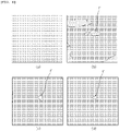
- FIG. 6 is a view for describing a count area.
- the intraoral scanner 1 performs the foreign matter detecting operation (S30) of confirming whether the foreign matter f is stained on the optical element 40 based on the image data acquired in the above-described image recognizing operation.
- the image data captured by the cameras 21 and 22 and generated by the imaging sensor 30 is displayed in real time on a display device connected to the intraoral scanner 1. This is to enable the patient's affected object to be stably scanned by displaying the portion illuminated by the user of the intraoral scanner 1 in real time. Meanwhile, a count area having the size corresponding to the image generated by the imaging sensor 30 (which is digitized with respect to the captured area) is generated and displayed on a screen of the display device. At this time, the count area is not an area where images captured by the cameras 21 and 22 are directly displayed, but is a virtual area for determining whether the measurement result data exists.
- the count area is composed of pixels, and each pixel may be formed to have the size corresponding to the image data generated by capturing the object.
- the count area may also be formed to have the same size as the image data generated by the imaging sensor 30.
- the count area may be formed to have the one-to-one correspondence with the image data.
- initial values are allocated to all pixels to initialize pixel values configuring the count area (base operation (S31)). Pixels in which the initial values are allocated to the pixel values are expressed in black on the display device when viewed with naked eye.
- the pixel value may have a range from 0 to 255, and when the pixel value is 0, the pixel is expressed in black, and when the pixel value is 255, the pixel is expressed in white, so that the pixel becomes brighter as the pixel value increases.
- the pixel value allocated to each pixel may be expressed as a change in brightness of an achromatic color in the count area according to a gray scale.
- an initial value may be any value from 0 to 255, but to effectively compare a portion where the measurement result exists and a portion where the measurement result does not exist, it is preferable that the initial values of the pixels allocated in the base operation are set to 0.
- the base operation (S31) When the base operation (S31) is performed, an additional value is added so that the pixel values of the count area corresponding to the portion where the measurement result does not exist in the image data acquired in the above-described image recognizing operation are changed (specifying operation (S32)). Accordingly, the count area corresponding to the portion where the measurement result does not exist has a brighter color compared to the pixel where the measurement result exists.
- the pixel value is an integer value having a value from 0 to 255
- the addition value may be set to 1.
- the initial values are again allocated to the pixel values of the count area corresponding to the portion where the measurement result exists in the image data acquired in the image recognizing operation (S20) (reallocating operation (S33)). It is practically difficult to detect the foreign matter f from the image data acquired by one single capturing, and even when the foreign matter f is detected by one single capturing, the reliability of the detection may not be guaranteed. Accordingly, for the portion where the measurement result does not momentarily exist by performing capturing a plurality of times, as a result, the pixel value is returned to the initial value to prevent the false detection of the foreign matter f.
- FIG. 5 shows that the reallocating operation (S33) is sequentially performed after the specifying operation (S32), but the present disclosure is not limited thereto. Since the image data generated by the captured area may be divided into the portion where the measurement result exists and the portion where the measurement result does not exist, it goes without saying that the specifying operation (S32) after the reallocating operation (S33) may also be performed, and the specifying operation (S32) and the reallocating operation (S33) may also be performed in parallel, as necessary.
- a determining operation (S34) of determining whether the foreign matter f exists in the optical element 40 of the intraoral scanner 1 is performed.
- the determining operation when the pixel values allocated to the pixels configuring the count area are less than a predesignated first set value, it is determined that the foreign matter f is not found or foreign matter image f' is not specified enough to determine that the foreign matter f exists, and a new image is captured and recognized (re-recognizing operation (S35)).
- the first set value is a preset value, and may be set to a value determined to be clear enough to distinguish the foreign matter image f' displayed on the count area from surrounding areas.
- the specifying operation (S32) of adding 1 to a count area pixel value corresponding to the portion where the measurement result does not exist again, and the reallocating operation (S33) of allocating 0 to the count area pixel value corresponding to the portion where the measurement result exists are performed again.
- the area corresponding to the portion where the measurement result does not exist on the count area gradually becomes brighter due to the increase in the pixel value.
- (a) to (d) of FIG. 6 show the count areas when 1 second ((a) of FIG. 6 ), 10 seconds ((b) of FIG. 6 ), 30 seconds ((c) of FIG. 6 ), and 60 seconds ((d) of FIG. 6 ) have elapsed since the foreign matter f was detected, respectively.
- the triangularshaped foreign matter image f' in the central portion of each drawing gradually becomes brighter as the foreign matter f detecting operation is repeated over time.
- the elapsed times (1 second, 10 seconds, 30 seconds, and 60 seconds) are illustrative, and may mean that the count area varies according to a first elapsed time, a second elapsed time, a third elapsed time, and a fourth elapsed time.
- the drawing is to describe that the foreign matter detecting operation (S30) is performed and the foreign matter image f' appears clearly over time.
- At least a part of the count area when the second elapsed time has elapsed is expressed brighter than in (a) of FIG. 6 .
- there is no foreign matter f attached to the optical element but a noise data area or the area where the measurement result does not exist may instantaneously occur.
- a predetermined pixel value may be added to the count area corresponding to the image data received in the specifying operation (S32).
- the fourth elapsed time may refer to a time for which the foreign matter image f' may be clearly distinguished and expressed compared to other areas. Through the clearly displayed foreign matter image f', the user may easily confirm whether the foreign matter has been attached to the optical element.
- the initial value is reallocated in the reallocating operation (S33) when data is input by the normal measurement again later even when the pixel value may be added by the specifying operation (S32) because data is not temporarily input due to other reasons irrelevant to the attachment of the foreign matter. Accordingly, it is possible to prevent the false detection of the foreign matter due to a temporary data input error and improve the reliability of the method for investigating the optical element.
- the specifying operation (S32) may be performed at an interval of 1 second or less.
- a time interval until the specifying operation is performed again through the re-recognizing operation after the specifying operation may be 1 second or less.
- the time interval is longer, the total time required for detecting the foreign matter f gets longer, making it difficult to quickly detect the foreign matter f. Accordingly, it is preferable that a time between a certain specifying operation and the next specifying is one second or less.
- an operation of generating a notification on the display device is performed.
- Generating the notification on the display device may be outputting a message requesting the inspection of the optical element 40 according to the detection of the foreign matter f or damage to the optical element 40 in a new pop-up window, or outputting a message to replace the tip case 14 formed therein from the optical element 40.
- generating the notification on the display device may be not only outputting the message on the display device but also generating a notification sound.
- the user may inspect the state of the optical element 40 of the intraoral scanner 1 in use or replace the tip case 14 in which the optical element 40 is disposed, and the user may perform the scan operation without directly inspecting the state of the optical element 40 from time to time, so that it is possible not only to improve the user's operation efficiency, but also improve the scan reliability of the intraoral scanner 1.
- the foreign matter f stained on a small area does not cause a big problem in measurement, and may be a material that may be separated while the intraoral scanner 1 is used as dust of a very small size. Accordingly, in this case, when the area where the measurement result does not exist is greater than or equal to an area of a specific size, it may be determined that the foreign matter f is stained on the optical element 40.
- the method for investigating the optical element may perform the specifying operation and the reallocating operation again by capturing and recognizing a new image when the count area pixel value is less than the first set value or when the number of pixels in which the count area pixel value is greater than or equal to the first set value is counted and the number of pixels counted is less than the second set value, and perform the notification generating operation (S40) when the number of pixels in which the count area pixel value is greater than or equal to the first set value is counted and the number of pixels counted is greater than or equal to the second set value.
- the first set value is the same as described above, and the second set value is a preset value for the number of pixels satisfying the condition in which the pixel value is greater than or equal to the first set value.
- the second set value is a reference value for an area of a pixel having a brightness greater than or equal to a specific brightness, and when the number of pixels counted is greater than or equal to the second set value, this is determined as the foreign matter f. Accordingly, in this case, the notification generating operation (S40) is performed only when the two set value criteria are all satisfied, so that it is possible to improve the accuracy of detecting the presence or absence of the foreign matter f.
- FIG. 7 is a schematic view of a system for investigating the optical element according to the present disclosure.
- the system for investigating the optical element may include the intraoral scanner 1.
- the intraoral scanner 1 may include the case 10 that may be drawn into and drawn out from the oral cavity, and is formed with an opening that is open so that the state inside the oral cavity is incident therein in the form of light through one end, at least one imaging unit 20 configured to generate image data by receiving light incident through the opening of the case 10, the light irradiation unit 30 disposed at one side of the imaging unit, and configured to emit light to irradiate the state inside the oral cavity through the opening, and the optical element configured to illuminate the object by refracting or reflecting light generated from the light irradiation unit 30, and cause light reflected from the object to enter into the imaging unit 20.
- an operating principle of the intraoral scanner 1 is the same as described above in the method for investigating the optical element using the intraoral scanner 1.
- the optical element investigation unit 200 may include a display unit 210 configured to display the count area with the size corresponding to the image generated by the imaging unit 20, and a determination unit 220 configured to determine whether the foreign matter is stained by the operation of the count area.
- the optical element investigation unit 200 may also be formed to be spaced apart from the intraoral scanner 1, but the present disclosure is not necessarily limited thereto, and may be formed inside the intraoral scanner 1, so that the intraoral scanner 1 may also self-investigate whether there is a problem in the state of the optical element
- the display unit 210 on which the count area is displayed is formed to be spaced apart from the intraoral scanner 1.
- the count area is generated on the display unit 210, and a pixel value of 0 is allocated to all pixels configuring the count area.
- the count area may have the size corresponding to the size of the image acquired by the imaging unit 20.
- the count area has the same size as that of the image acquired by the imaging unit 20, so that the pixels configuring the image data acquired by the imaging unit 20 have the one-to-one correspondence with the pixels configuring the count area, respectively.
- the imaging unit 20 when the initial values of the pixel values are allocated to all pixels configuring the count area and initialization is completed, an additional value is added to the pixel values of the count area corresponding to the portion where the measurement result does not exist from the image data generated by the imaging unit.
- the pixel value may be an integer value between 0 and 255, and as the pixel value increases from 0 to 255, the pixel may be displayed on the display unit 210 to gradually brighten from black to white.
- the imaging unit 20 when the imaging unit 20 generates image data in order to continuously investigate the state of the optical element, the portion where the foreign matter is stained continuously appears as the portion where the measurement result does not exist, whereas the measurement result does not momentarily exist in other portions, and portions where the measurement result is received again appear.
- the initial values are again reallocated to the pixel values of the count area corresponding to the portion where the measurement result exists.
- the optical element investigation unit 200 adds the additional value to the pixel values of the count area corresponding to the portions in which the measurement result does not exist, and the initial values are reallocated to the pixel values of the count area corresponding to the portions in which the measurement result is received, so that it is possible to perform a clear foreign matter detection.
- the initial value and the additional value may preferably be 0 and 1, respectively, as described above.
- the determination unit 220 may determine that the foreign matter is attached to the optical element to control the notification unit to generate the notification.
- the determination unit 220 may be a processor configured to apply the control signal to each unit configuring the system, or determine whether the foreign matter is detected with respect to the pixel values of the count area displayed on the display unit 210.
- the determination unit 220 may count the number of pixels in which the count area pixel value is the first set value, and control the notification unit to generate the notification when the number of pixels counted is greater than or equal to the second set value.
- the notification signal may be expressed in various methods, such as a vibration signal, a sound signal, and a light emission signal, generated by the intraoral scanner.
- the count area may be displayed in the form of a pop-up on the display unit 210 to notify the user of the inspection and replacement of the optical element.
- the present disclosure relates to the method and system for investigating the optical element embedded in the intraoral scanner, and it is possible to easily maintain the intraoral scanner by enabling the user to recognize it when it is determined that the foreign matter is attached to the optical element. Accordingly, it is possible to improve the scan efficiency of the intraoral scanner.
Landscapes
- Health & Medical Sciences (AREA)
- Life Sciences & Earth Sciences (AREA)
- Physics & Mathematics (AREA)
- General Health & Medical Sciences (AREA)
- General Physics & Mathematics (AREA)
- Engineering & Computer Science (AREA)
- Public Health (AREA)
- Veterinary Medicine (AREA)
- Animal Behavior & Ethology (AREA)
- Oral & Maxillofacial Surgery (AREA)
- Dentistry (AREA)
- Pathology (AREA)
- Epidemiology (AREA)
- Immunology (AREA)
- Biochemistry (AREA)
- Analytical Chemistry (AREA)
- Chemical & Material Sciences (AREA)
- Optics & Photonics (AREA)
- Biomedical Technology (AREA)
- Biophysics (AREA)
- Surgery (AREA)
- Medical Informatics (AREA)
- Molecular Biology (AREA)
- Heart & Thoracic Surgery (AREA)
- Nuclear Medicine, Radiotherapy & Molecular Imaging (AREA)
- Radiology & Medical Imaging (AREA)
- Theoretical Computer Science (AREA)
- Audiology, Speech & Language Pathology (AREA)
- Computer Vision & Pattern Recognition (AREA)
- Quality & Reliability (AREA)
- Dental Tools And Instruments Or Auxiliary Dental Instruments (AREA)
- Endoscopes (AREA)
Applications Claiming Priority (2)
| Application Number | Priority Date | Filing Date | Title |
|---|---|---|---|
| KR1020190175290A KR102370017B1 (ko) | 2019-12-26 | 2019-12-26 | 구강스캐너에 내장된 광학요소 검사 방법 및 이를 이용한 시스템 |
| PCT/KR2020/019072 WO2021133090A2 (ko) | 2019-12-26 | 2020-12-24 | 구강스캐너에 내장된 광학요소 검사 방법 및 이를 이용한 시스템 |
Publications (4)
| Publication Number | Publication Date |
|---|---|
| EP4062866A2 true EP4062866A2 (de) | 2022-09-28 |
| EP4062866A4 EP4062866A4 (de) | 2023-11-22 |
| EP4062866C0 EP4062866C0 (de) | 2025-07-30 |
| EP4062866B1 EP4062866B1 (de) | 2025-07-30 |
Family
ID=76573326
Family Applications (1)
| Application Number | Title | Priority Date | Filing Date |
|---|---|---|---|
| EP20907029.1A Active EP4062866B1 (de) | 2019-12-26 | 2020-12-24 | Verfahren zur untersuchung eines in einem intraoralen scanner eingebetteten optischen elements und system unter verwendung desselben |
Country Status (4)
| Country | Link |
|---|---|
| US (1) | US12533033B2 (de) |
| EP (1) | EP4062866B1 (de) |
| KR (1) | KR102370017B1 (de) |
| WO (1) | WO2021133090A2 (de) |
Families Citing this family (11)
| Publication number | Priority date | Publication date | Assignee | Title |
|---|---|---|---|---|
| JP1711307S (ja) * | 2021-02-08 | 2022-03-30 | 歯科用スキャナー | |
| JP1723389S (ja) * | 2021-12-14 | 2022-08-29 | 口腔内スキャナー | |
| USD1042842S1 (en) * | 2022-02-18 | 2024-09-17 | Align Technology, Inc. | Intraoral scanner wand |
| USD988513S1 (en) * | 2022-08-19 | 2023-06-06 | Sprintray Inc. | Intraoral scanner |
| USD1048401S1 (en) * | 2022-12-08 | 2024-10-22 | 3Shape A/S | Scanner tip |
| USD1051387S1 (en) * | 2022-12-08 | 2024-11-12 | 3Shape A/S | Scanner with a tip |
| USD1101031S1 (en) * | 2022-12-08 | 2025-11-04 | 3Shape A/S | Scanner without tip |
| CN116245804A (zh) * | 2022-12-22 | 2023-06-09 | 先临三维科技股份有限公司 | 口内扫描仪的异物识别方法、装置、设备及存储介质 |
| WO2025084562A1 (ko) * | 2023-10-20 | 2025-04-24 | 아크리얼 주식회사 | 구강 스캐닝 시스템 |
| KR102926252B1 (ko) * | 2023-10-20 | 2026-02-12 | 아크리얼 주식회사 | 실시간으로 피드백을 제공할 수 있는 구강 스캐닝 시스템 |
| WO2025211794A1 (ko) * | 2024-04-03 | 2025-10-09 | 주식회사 메디트 | 터치 센서를 포함하는 3차원 핸드헬드 스캐너 |
Family Cites Families (17)
| Publication number | Priority date | Publication date | Assignee | Title |
|---|---|---|---|---|
| JP4996856B2 (ja) * | 2006-01-23 | 2012-08-08 | 株式会社日立ハイテクノロジーズ | 欠陥検査装置およびその方法 |
| JP5260188B2 (ja) * | 2008-08-27 | 2013-08-14 | 富士フイルム株式会社 | ハードディスク検査装置及び方法並びにプログラム |
| JP2012147909A (ja) | 2011-01-18 | 2012-08-09 | Olympus Corp | 歯牙観察装置 |
| KR101418403B1 (ko) | 2012-12-14 | 2014-07-09 | 라파바이오 주식회사 | 구강용 3차원 스캐너 |
| US10073044B2 (en) * | 2014-05-16 | 2018-09-11 | Ncr Corporation | Scanner automatic dirty/clean window detection |
| KR101662566B1 (ko) * | 2015-05-20 | 2016-10-05 | 주식회사바텍 | 광학부 교환에 의해 스캔 영역과 정밀도 변경이 가능한 구강스캐너 |
| US12285307B2 (en) * | 2016-02-17 | 2025-04-29 | Peter Wohrle | System and method for guiding medical instruments |
| KR101792542B1 (ko) * | 2016-03-30 | 2017-11-02 | 주식회사바텍 | 착탈식 모듈을 갖는 치과용 3차원 스캐너 |
| US10229495B2 (en) * | 2016-11-22 | 2019-03-12 | Agilent Technologies, Inc. | Method for unsupervised stain separation in pathological whole slide images |
| BR102016028266A2 (pt) * | 2016-12-01 | 2018-06-19 | Autaza Tecnologia Ltda - Epp | Método e sistema para a inspeção automática de qualidade de materiais |
| JP6752710B2 (ja) * | 2016-12-27 | 2020-09-09 | グローリー株式会社 | 撮像装置、汚れ検知システム、及び、汚れ検知方法 |
| KR20180133577A (ko) * | 2017-06-07 | 2018-12-17 | 클라우드라인주식회사 | 광화각을 갖는 구강영상의 취득이 가능한 구강 카메라 장치 |
| KR102042024B1 (ko) * | 2017-12-14 | 2019-11-07 | 주식회사 바텍 | 구강 스캐너 |
| KR101874547B1 (ko) * | 2018-05-03 | 2018-07-04 | 주식회사 메디트 | 3차원 구강 스캐너 |
| JP6933608B2 (ja) * | 2018-06-01 | 2021-09-08 | ファナック株式会社 | 視覚センサのレンズまたはレンズカバーの異常検出システム |
| CN112334755A (zh) * | 2018-06-22 | 2021-02-05 | 三菱电机株式会社 | 粒子检测装置 |
| US11291404B2 (en) * | 2019-09-24 | 2022-04-05 | Dentsply Sirona Inc. | Method, system and computer readable storage media for the detection of errors in three-dimensional measurements |
-
2019
- 2019-12-26 KR KR1020190175290A patent/KR102370017B1/ko active Active
-
2020
- 2020-12-24 WO PCT/KR2020/019072 patent/WO2021133090A2/ko not_active Ceased
- 2020-12-24 EP EP20907029.1A patent/EP4062866B1/de active Active
-
2022
- 2022-06-24 US US17/848,699 patent/US12533033B2/en active Active
Also Published As
| Publication number | Publication date |
|---|---|
| WO2021133090A2 (ko) | 2021-07-01 |
| WO2021133090A3 (ko) | 2021-08-19 |
| EP4062866C0 (de) | 2025-07-30 |
| EP4062866B1 (de) | 2025-07-30 |
| EP4062866A4 (de) | 2023-11-22 |
| KR20210082883A (ko) | 2021-07-06 |
| US20220313094A1 (en) | 2022-10-06 |
| US12533033B2 (en) | 2026-01-27 |
| KR102370017B1 (ko) | 2022-03-04 |
Similar Documents
| Publication | Publication Date | Title |
|---|---|---|
| US12533033B2 (en) | Method for investigating optical element embedded in intraoral scanner, and system using same | |
| EP3028003B1 (de) | Verfahren und systeme zur erzeugung von farbbildern | |
| CN108445007A (zh) | 一种基于图像融合的检测方法及其检测装置 | |
| KR101203210B1 (ko) | 결함 검사장치 | |
| WO2012161239A1 (ja) | 内視鏡装置 | |
| JP2009168582A (ja) | 外観検査装置 | |
| JP2018527962A (ja) | プルキンエ計測器及び自動評価方法 | |
| CN113645922A (zh) | 光学龋齿诊断仪、光学龋齿诊断方法和龋齿诊断系统 | |
| CN1991435B (zh) | 用于光学扫描表面的扫描设备 | |
| WO2017029670A1 (en) | Intra-oral mapping of edentulous or partially edentulous mouth cavities | |
| CN114383521B (zh) | 自动涡轮叶片与护罩间隙测量 | |
| WO2004065903A1 (ja) | 容器の口部検査装置 | |
| US20130130191A1 (en) | Optical tomography image acquisition device | |
| CN104897680A (zh) | 物件检测方法及装置 | |
| JP2009042093A (ja) | 電子部品検査装置および電子部品検査方法 | |
| EP2739206B1 (de) | Adaptives belichtungsverfahren und vorrichtung zur zahnschattierungsanpassung | |
| KR102559164B1 (ko) | 이미지 처리 장치 및 이미지 처리 방법 | |
| CN120379585A (zh) | 口内3d扫描仪校准 | |
| KR102632337B1 (ko) | 얼라인 상태 표현 장치 및 방법 | |
| JP4104302B2 (ja) | 前眼部断面解析装置及び前眼部断面解析プログラム | |
| JP2020153684A (ja) | 画像測定装置 | |
| JP2010025805A (ja) | 深さ測定装置及び深さ測定方法 | |
| KR200176154Y1 (ko) | 3디센서를 이용한 아이시 및 패턴드 웨이퍼의 3차원 외관검사장치 | |
| KR200176165Y1 (ko) | 3디센서를 이용한 아이시 및 패턴드 웨이퍼의 3차원 외관및 대미지 검사장치 | |
| JP2007071745A (ja) | 照明用光学素子の検査装置 |
Legal Events
| Date | Code | Title | Description |
|---|---|---|---|
| STAA | Information on the status of an ep patent application or granted ep patent |
Free format text: STATUS: THE INTERNATIONAL PUBLICATION HAS BEEN MADE |
|
| PUAI | Public reference made under article 153(3) epc to a published international application that has entered the european phase |
Free format text: ORIGINAL CODE: 0009012 |
|
| STAA | Information on the status of an ep patent application or granted ep patent |
Free format text: STATUS: REQUEST FOR EXAMINATION WAS MADE |
|
| 17P | Request for examination filed |
Effective date: 20220623 |
|
| AK | Designated contracting states |
Kind code of ref document: A2 Designated state(s): AL AT BE BG CH CY CZ DE DK EE ES FI FR GB GR HR HU IE IS IT LI LT LU LV MC MK MT NL NO PL PT RO RS SE SI SK SM TR |
|
| DAV | Request for validation of the european patent (deleted) | ||
| DAX | Request for extension of the european patent (deleted) | ||
| REG | Reference to a national code |
Ref country code: DE Ref legal event code: R079 Free format text: PREVIOUS MAIN CLASS: A61C0009000000 Ipc: G01B0011240000 Ref document number: 602020055687 Country of ref document: DE |
|
| A4 | Supplementary search report drawn up and despatched |
Effective date: 20231024 |
|
| RIC1 | Information provided on ipc code assigned before grant |
Ipc: G01N 21/958 20060101ALI20231019BHEP Ipc: G01N 21/94 20060101ALI20231019BHEP Ipc: A61C 9/00 20060101ALI20231019BHEP Ipc: G01B 11/24 20060101AFI20231019BHEP |
|
| GRAP | Despatch of communication of intention to grant a patent |
Free format text: ORIGINAL CODE: EPIDOSNIGR1 |
|
| STAA | Information on the status of an ep patent application or granted ep patent |
Free format text: STATUS: GRANT OF PATENT IS INTENDED |
|
| INTG | Intention to grant announced |
Effective date: 20250228 |
|
| GRAS | Grant fee paid |
Free format text: ORIGINAL CODE: EPIDOSNIGR3 |
|
| GRAA | (expected) grant |
Free format text: ORIGINAL CODE: 0009210 |
|
| STAA | Information on the status of an ep patent application or granted ep patent |
Free format text: STATUS: THE PATENT HAS BEEN GRANTED |
|
| AK | Designated contracting states |
Kind code of ref document: B1 Designated state(s): AL AT BE BG CH CY CZ DE DK EE ES FI FR GB GR HR HU IE IS IT LI LT LU LV MC MK MT NL NO PL PT RO RS SE SI SK SM TR |
|
| REG | Reference to a national code |
Ref country code: GB Ref legal event code: FG4D |
|
| REG | Reference to a national code |
Ref country code: CH Ref legal event code: EP |
|
| REG | Reference to a national code |
Ref country code: DE Ref legal event code: R096 Ref document number: 602020055687 Country of ref document: DE |
|
| REG | Reference to a national code |
Ref country code: IE Ref legal event code: FG4D |
|
| U01 | Request for unitary effect filed |
Effective date: 20250825 |
|
| U07 | Unitary effect registered |
Designated state(s): AT BE BG DE DK EE FI FR IT LT LU LV MT NL PT RO SE SI Effective date: 20250829 |
|
| PG25 | Lapsed in a contracting state [announced via postgrant information from national office to epo] |
Ref country code: IS Free format text: LAPSE BECAUSE OF FAILURE TO SUBMIT A TRANSLATION OF THE DESCRIPTION OR TO PAY THE FEE WITHIN THE PRESCRIBED TIME-LIMIT Effective date: 20251130 |
|
| PGFP | Annual fee paid to national office [announced via postgrant information from national office to epo] |
Ref country code: GB Payment date: 20251218 Year of fee payment: 6 |
|
| PG25 | Lapsed in a contracting state [announced via postgrant information from national office to epo] |
Ref country code: NO Free format text: LAPSE BECAUSE OF FAILURE TO SUBMIT A TRANSLATION OF THE DESCRIPTION OR TO PAY THE FEE WITHIN THE PRESCRIBED TIME-LIMIT Effective date: 20251030 |
|
| PG25 | Lapsed in a contracting state [announced via postgrant information from national office to epo] |
Ref country code: HR Free format text: LAPSE BECAUSE OF FAILURE TO SUBMIT A TRANSLATION OF THE DESCRIPTION OR TO PAY THE FEE WITHIN THE PRESCRIBED TIME-LIMIT Effective date: 20250730 |
|
| PG25 | Lapsed in a contracting state [announced via postgrant information from national office to epo] |
Ref country code: GR Free format text: LAPSE BECAUSE OF FAILURE TO SUBMIT A TRANSLATION OF THE DESCRIPTION OR TO PAY THE FEE WITHIN THE PRESCRIBED TIME-LIMIT Effective date: 20251031 |
|
| U20 | Renewal fee for the european patent with unitary effect paid |
Year of fee payment: 6 Effective date: 20251218 |
|
| PG25 | Lapsed in a contracting state [announced via postgrant information from national office to epo] |
Ref country code: PL Free format text: LAPSE BECAUSE OF FAILURE TO SUBMIT A TRANSLATION OF THE DESCRIPTION OR TO PAY THE FEE WITHIN THE PRESCRIBED TIME-LIMIT Effective date: 20250730 |
|
| PG25 | Lapsed in a contracting state [announced via postgrant information from national office to epo] |
Ref country code: RS Free format text: LAPSE BECAUSE OF FAILURE TO SUBMIT A TRANSLATION OF THE DESCRIPTION OR TO PAY THE FEE WITHIN THE PRESCRIBED TIME-LIMIT Effective date: 20251030 |
|
| PG25 | Lapsed in a contracting state [announced via postgrant information from national office to epo] |
Ref country code: ES Free format text: LAPSE BECAUSE OF FAILURE TO SUBMIT A TRANSLATION OF THE DESCRIPTION OR TO PAY THE FEE WITHIN THE PRESCRIBED TIME-LIMIT Effective date: 20250730 |
|
| PG25 | Lapsed in a contracting state [announced via postgrant information from national office to epo] |
Ref country code: SM Free format text: LAPSE BECAUSE OF FAILURE TO SUBMIT A TRANSLATION OF THE DESCRIPTION OR TO PAY THE FEE WITHIN THE PRESCRIBED TIME-LIMIT Effective date: 20250730 |