EP4061196B1 - Optische vorrichtung - Google Patents
Optische vorrichtung Download PDFInfo
- Publication number
- EP4061196B1 EP4061196B1 EP20811060.1A EP20811060A EP4061196B1 EP 4061196 B1 EP4061196 B1 EP 4061196B1 EP 20811060 A EP20811060 A EP 20811060A EP 4061196 B1 EP4061196 B1 EP 4061196B1
- Authority
- EP
- European Patent Office
- Prior art keywords
- optical element
- image plane
- optical
- optical path
- final image
- Prior art date
- Legal status (The legal status is an assumption and is not a legal conclusion. Google has not performed a legal analysis and makes no representation as to the accuracy of the status listed.)
- Active
Links
Images




Classifications
-
- A—HUMAN NECESSITIES
- A61—MEDICAL OR VETERINARY SCIENCE; HYGIENE
- A61B—DIAGNOSIS; SURGERY; IDENTIFICATION
- A61B1/00—Instruments for performing medical examinations of the interior of cavities or tubes of the body by visual or photographical inspection, e.g. endoscopes; Illuminating arrangements therefor
- A61B1/227—Instruments for performing medical examinations of the interior of cavities or tubes of the body by visual or photographical inspection, e.g. endoscopes; Illuminating arrangements therefor for ears, i.e. otoscopes
-
- A—HUMAN NECESSITIES
- A61—MEDICAL OR VETERINARY SCIENCE; HYGIENE
- A61B—DIAGNOSIS; SURGERY; IDENTIFICATION
- A61B1/00—Instruments for performing medical examinations of the interior of cavities or tubes of the body by visual or photographical inspection, e.g. endoscopes; Illuminating arrangements therefor
-
- A—HUMAN NECESSITIES
- A61—MEDICAL OR VETERINARY SCIENCE; HYGIENE
- A61B—DIAGNOSIS; SURGERY; IDENTIFICATION
- A61B1/00—Instruments for performing medical examinations of the interior of cavities or tubes of the body by visual or photographical inspection, e.g. endoscopes; Illuminating arrangements therefor
- A61B1/00002—Operational features of endoscopes
- A61B1/00004—Operational features of endoscopes characterised by electronic signal processing
- A61B1/00009—Operational features of endoscopes characterised by electronic signal processing of image signals during a use of endoscope
-
- A—HUMAN NECESSITIES
- A61—MEDICAL OR VETERINARY SCIENCE; HYGIENE
- A61B—DIAGNOSIS; SURGERY; IDENTIFICATION
- A61B1/00—Instruments for performing medical examinations of the interior of cavities or tubes of the body by visual or photographical inspection, e.g. endoscopes; Illuminating arrangements therefor
- A61B1/00064—Constructional details of the endoscope body
- A61B1/00066—Proximal part of endoscope body, e.g. handles
-
- A—HUMAN NECESSITIES
- A61—MEDICAL OR VETERINARY SCIENCE; HYGIENE
- A61B—DIAGNOSIS; SURGERY; IDENTIFICATION
- A61B1/00—Instruments for performing medical examinations of the interior of cavities or tubes of the body by visual or photographical inspection, e.g. endoscopes; Illuminating arrangements therefor
- A61B1/00064—Constructional details of the endoscope body
- A61B1/00071—Insertion part of the endoscope body
- A61B1/0008—Insertion part of the endoscope body characterised by distal tip features
- A61B1/00096—Optical elements
-
- A—HUMAN NECESSITIES
- A61—MEDICAL OR VETERINARY SCIENCE; HYGIENE
- A61B—DIAGNOSIS; SURGERY; IDENTIFICATION
- A61B1/00—Instruments for performing medical examinations of the interior of cavities or tubes of the body by visual or photographical inspection, e.g. endoscopes; Illuminating arrangements therefor
- A61B1/00163—Optical arrangements
- A61B1/00188—Optical arrangements with focusing or zooming features
-
- A—HUMAN NECESSITIES
- A61—MEDICAL OR VETERINARY SCIENCE; HYGIENE
- A61B—DIAGNOSIS; SURGERY; IDENTIFICATION
- A61B1/00—Instruments for performing medical examinations of the interior of cavities or tubes of the body by visual or photographical inspection, e.g. endoscopes; Illuminating arrangements therefor
- A61B1/012—Instruments for performing medical examinations of the interior of cavities or tubes of the body by visual or photographical inspection, e.g. endoscopes; Illuminating arrangements therefor characterised by internal passages or accessories therefor
- A61B1/018—Instruments for performing medical examinations of the interior of cavities or tubes of the body by visual or photographical inspection, e.g. endoscopes; Illuminating arrangements therefor characterised by internal passages or accessories therefor for receiving instruments
-
- A—HUMAN NECESSITIES
- A61—MEDICAL OR VETERINARY SCIENCE; HYGIENE
- A61B—DIAGNOSIS; SURGERY; IDENTIFICATION
- A61B1/00—Instruments for performing medical examinations of the interior of cavities or tubes of the body by visual or photographical inspection, e.g. endoscopes; Illuminating arrangements therefor
- A61B1/04—Instruments for performing medical examinations of the interior of cavities or tubes of the body by visual or photographical inspection, e.g. endoscopes; Illuminating arrangements therefor combined with photographic or television appliances
- A61B1/042—Instruments for performing medical examinations of the interior of cavities or tubes of the body by visual or photographical inspection, e.g. endoscopes; Illuminating arrangements therefor combined with photographic or television appliances characterised by a proximal camera, e.g. a CCD camera
-
- A—HUMAN NECESSITIES
- A61—MEDICAL OR VETERINARY SCIENCE; HYGIENE
- A61B—DIAGNOSIS; SURGERY; IDENTIFICATION
- A61B1/00—Instruments for performing medical examinations of the interior of cavities or tubes of the body by visual or photographical inspection, e.g. endoscopes; Illuminating arrangements therefor
- A61B1/06—Instruments for performing medical examinations of the interior of cavities or tubes of the body by visual or photographical inspection, e.g. endoscopes; Illuminating arrangements therefor with illuminating arrangements
- A61B1/0655—Control therefor
-
- A—HUMAN NECESSITIES
- A61—MEDICAL OR VETERINARY SCIENCE; HYGIENE
- A61B—DIAGNOSIS; SURGERY; IDENTIFICATION
- A61B1/00—Instruments for performing medical examinations of the interior of cavities or tubes of the body by visual or photographical inspection, e.g. endoscopes; Illuminating arrangements therefor
- A61B1/06—Instruments for performing medical examinations of the interior of cavities or tubes of the body by visual or photographical inspection, e.g. endoscopes; Illuminating arrangements therefor with illuminating arrangements
- A61B1/0661—Endoscope light sources
- A61B1/0669—Endoscope light sources at proximal end of an endoscope
-
- A—HUMAN NECESSITIES
- A61—MEDICAL OR VETERINARY SCIENCE; HYGIENE
- A61B—DIAGNOSIS; SURGERY; IDENTIFICATION
- A61B1/00—Instruments for performing medical examinations of the interior of cavities or tubes of the body by visual or photographical inspection, e.g. endoscopes; Illuminating arrangements therefor
- A61B1/06—Instruments for performing medical examinations of the interior of cavities or tubes of the body by visual or photographical inspection, e.g. endoscopes; Illuminating arrangements therefor with illuminating arrangements
- A61B1/0661—Endoscope light sources
- A61B1/0684—Endoscope light sources using light emitting diodes [LED]
-
- A—HUMAN NECESSITIES
- A61—MEDICAL OR VETERINARY SCIENCE; HYGIENE
- A61B—DIAGNOSIS; SURGERY; IDENTIFICATION
- A61B1/00—Instruments for performing medical examinations of the interior of cavities or tubes of the body by visual or photographical inspection, e.g. endoscopes; Illuminating arrangements therefor
- A61B1/32—Devices for opening or enlarging the visual field, e.g. of a tube of the body
-
- G—PHYSICS
- G02—OPTICS
- G02B—OPTICAL ELEMENTS, SYSTEMS OR APPARATUS
- G02B23/00—Telescopes, e.g. binoculars; Periscopes; Instruments for viewing the inside of hollow bodies; Viewfinders; Optical aiming or sighting devices
- G02B23/24—Instruments or systems for viewing the inside of hollow bodies, e.g. fibrescopes
- G02B23/2407—Optical details
- G02B23/2423—Optical details of the distal end
-
- G—PHYSICS
- G02—OPTICS
- G02B—OPTICAL ELEMENTS, SYSTEMS OR APPARATUS
- G02B23/00—Telescopes, e.g. binoculars; Periscopes; Instruments for viewing the inside of hollow bodies; Viewfinders; Optical aiming or sighting devices
- G02B23/24—Instruments or systems for viewing the inside of hollow bodies, e.g. fibrescopes
- G02B23/2407—Optical details
- G02B23/2461—Illumination
-
- A—HUMAN NECESSITIES
- A61—MEDICAL OR VETERINARY SCIENCE; HYGIENE
- A61B—DIAGNOSIS; SURGERY; IDENTIFICATION
- A61B2560/00—Constructional details of operational features of apparatus; Accessories for medical measuring apparatus
- A61B2560/04—Constructional details of apparatus
- A61B2560/0406—Constructional details of apparatus specially shaped apparatus housings
-
- A—HUMAN NECESSITIES
- A61—MEDICAL OR VETERINARY SCIENCE; HYGIENE
- A61B—DIAGNOSIS; SURGERY; IDENTIFICATION
- A61B2560/00—Constructional details of operational features of apparatus; Accessories for medical measuring apparatus
- A61B2560/04—Constructional details of apparatus
- A61B2560/0431—Portable apparatus, e.g. comprising a handle or case
Definitions
- the present application relates an apparatus for providing magnification of an object for a device having a camera.
- embodiments are directed to apparatus for medical visual examination and to apparatus for assisting a user in performing medical procedures.
- the application relates to an instrument configured for use with a mobile user device, providing enhanced image quality while maintaining sufficient access for tools.
- Some instruments incorporate traditional optical systems with mobile user devices, providing improved ergonomics, usability and cost for wider access to associated procedures such as micro-suction of the ear canal.
- Such instruments often exhibit poor image magnification and detail, and do not provide sufficient space for tool access.
- GB-A-2569325 discloses a handle, a speculum mount, a smartphone mount and a spacing element.
- the spacing element is configured to maintain an optical separation distance between the speculum mount and the smartphone mount.
- the apparatus also comprises optical paths for the smartphone's camera and light source and optical elements to focus the image and/or direct the light.
- the optical element may be configured to provide dual images to the smartphone's camera. In use the apparatus enables a clear view of the ear canal while allowing access of a micro-suction tool to be inserted into the ear canal.
- a cannula grip and guide for the micro-suction tool is also disclosed.
- US-A1-2015/234149 discloses a zoom lens system for a mobile phone camera including two or more zoom lens groups and an intermediate real image plane.
- US-A1-2017/293139 discloses an optical system for an endoscope including a reversal system for projecting a distal intermediate image onto a proximal intermediate image plane, where the system enables sharp imaging in the near infrared range.
- apparatus for providing magnification of an object for a device having a camera, the apparatus comprising:
- the apparatus can provide greatly increased magnification of objects undergoing examination, while providing clear space for tool access to the objects.
- the use of two optical elements arranged as described significantly increases the magnification of the object while the spacing element maintains the object at a fixed distance from the first optical element thus allowing a space for tool access to be provided.
- the second distance may be at least twice the first distance and preferably around 5 times larger than the first distance.
- the second distance may be at least around a decimal order of magnitude greater than the first distance. It is noted that the distance along the optical path may be significantly greater than the physical straight-line distance, in particular if the optical path is bent and diverted as described in more detail below.
- the device may simply comprise a camera and hardware and software for operating the camera
- the device having a camera comprises a mobile user device such as a smartphone or tablet device. It may also comprise a custom device that includes a camera, hardware and software and optionally a screen and wireless communication capabilities.
- the apparatus may further comprise a body for defining an aperture through which human or animal anatomical structures are examined.
- the optical path preferably passes through the aperture.
- the body may be a speculum for placing in a patient's ear canal.
- the apparatus may comprise an otoscope.
- the speculum may be disposed at the distal end of the spacing element, and the spacing element may be configured to provide a gap for tool access to the ear canal through the speculum.
- the apparatus may further comprise a third optical element disposed on the optical path at the intermediate image plane.
- the third optical element may contain the entire image at the intermediate image plane, and may be arranged such that the first optical element and the second optical element lie in conjugate planes.
- this feature reduces in the final image vignetting effects resulting from light at higher field angles missing the second optical element.
- At least one, preferably each, optical element may comprise a lens.
- the first optical element may comprise two doublets.
- the apparatus may further comprise an aperture stop disposed on the optical path, wherein the aperture stop effects a reduction in the diameter of the entrance pupil of the apparatus, optionally wherein the first optical element comprises two doublets and the aperture stop is disposed between the two doublets. This increases the depth of field in the final image by increasing the f-number of the optics.
- the apparatus may further comprise a mirror arrangement comprising a plurality of mirrors arranged to divert the optical path away from and then towards an axis extending between the first optical element and the final image plane, such that the optical path is longer than the distance between the first optical element and the final image plane.
- the plurality of mirrors may divert the optical path to a plane substantially parallel and proximate to a distal surface of the device, that is, along a path parallel to the back of the mobile device. This offers the advantage of being able to fold a section of the optical path, providing a more compact and ergonomic apparatus while maintaining sufficient clear space for tool access.
- the first optical element may be achromatic.
- the front focal length of the first optical element may be no less than around 80 mm, preferably no less than 100 mm.
- the front focal length of the first optical element may be no greater than around 180 mm, preferably no greater than 150 mm.
- the power of the second optical element may be no less than around 3 dioptres, preferably no less than 5 dioptres.
- the power of the second optical element may be no greater than around 25 dioptres, preferably no greater than 23 dioptres.
- An accompanying application may be provided for the mobile computing device having a camera receiving an image from the apparatus described above and such an application may be configured to crop the image, digitally magnify the image and/or invert the image in real-time.
- the method may further comprise the step of arranging a plurality of mirrors to divert the optical path away from and then towards an axis extending between the first optical element and the final image plane, such that the optical path is longer that the distance between the first optical element and the final image plane.
- the method may further comprise the step of arranging the plurality of mirrors to divert the optical path to a plane substantially parallel and proximate to a distal surface of the device.
- the method may further comprise the step of installing the optical elements and the plurality of mirrors in a housing, wherein the housing is partially or totally sealed and provides space for the optical path through one or more internal cavities.
- the method may further comprise the step of illuminating the object using a powered light source and an associated optical arrangement, the light source preferably being a plurality of white light LEDs.
- the powered light source may be provided by the device.
- the method may further comprise the steps of controlling the powered light source using electronic circuitry and attaching the electronic circuitry to the spacing element.
- the method may further comprise coupling a handle to the spacing element.
- the method may further comprise powering the powered light source using a power source and associated electronic circuitry.
- the power source and the associated electronic circuitry may be disposed in the handle.
- any feature in one aspect of the invention may be applied to other aspects of the invention, in any appropriate combination.
- method aspects may be applied to system aspects, and vice versa.
- any, some and/or all features in one aspect can be applied to any, some and/or all features in any other aspect, in any appropriate combination.
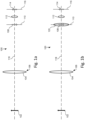
- the apparatus comprises a first optical element 104 at a first location 106, and a second optical element 112.
- the first optical element 104 provides an image 108 of the object 102 in an intermediate image plane 110.
- the image 108 is then magnified optically by the second optical element 112 to provide a final image 114 in a final image plane 116.
- the intermediate image plane 110 and the second optical element 112 are arranged along an optical path 118 extending between the first optical element 104 and the final image plane 116.
- the focal lengths of the optical elements 104, 112 are such that the distance from the first optical element 104 to the intermediate image plane 110 is greater than the distance from the intermediate image plane 110 to the second optical element 112.
- a third optical element 120 may be provided at the intermediate image plane 110, such that the third optical element 120 contains the entire image 108.
- the third optical element 120 is arranged such that the first optical element 104 and the second optical element 112 lie in conjugate planes.
- a spacing element maintains a fixed separation between the first optical element 104 and the object 102.
- Means for mounting the apparatus 100 in a fixed position relative to the mobile user device is provided (also not illustrated in Figure 1a or 1b ) such that a camera aperture of the mobile user device is supported in the final image plane 116.
- At least one, preferably each, optical element is a lens or a system of lenses.
- the length of the optical path 118 taken between two locations will be referred to as a distance along the optical path 118, and is distinct from the shortest spatial distance between the two locations.
- the distance along the optical path 118 from the intermediate image plane 110 to the final image plane 116 is significantly smaller than the distance along the optical path 118 from the intermediate image plane 110 to the first optical element 104.
- Figures 1a and 1b are not drawn to scale and the distance between the first optical element 104 and the plane of the object 102 may be greater than the spatial distance between the optical elements 104, 112 and the spatial distance between the first optical element 104 and the image plane 116. That is, the spacing element is arranged to provide a gap large enough to allow access for surgical tools or other devices.
- the end of the apparatus 100 nearest to the object 102 will be referred to as the distal end, i.e. the end which is furthest from the user, and the end of the apparatus 100 nearest to the mobile user device will be referred to as the proximal end, i.e. the end closest to the user.
- the second optical element 112 is arranged to reduce the minimum focusing distance (and effective focal length) of the camera, allowing the image 108 to be placed closer to the final image plane 116 for an in-focus final image 114.
- the apparatus 100 may be used for medical examinations and any coupled procedures. Accordingly, by way of example, the apparatus 100 may be incorporated into or implemented in conjunction with medical devices such as otoscopes, endoscopes or ophthalmoscopes, for examination of internal or external anatomical structures.
- medical devices such as otoscopes, endoscopes or ophthalmoscopes
- the first optical element 104 has a focal length of approximately 100 mm -150mm and is placed along the optical path 118 approximately one focal length away from the object 102.
- the intermediate image plane 110 is therefore approximately 300 mm along the optical path 118 from the first optical element 104.
- magnification can be achieved using the first optical element 104, found as the ratio of the distances along the optical path 118 from the first optical element 104 to the object 102 and from the first optical element 104 to the intermediate image plane 110.
- the second optical element 112 has a power of approximately 10 dioptres and reduces the minimum focusing distance of the camera by a factor of 1.6, and in combination with the first optical element 104 has a magnification factor of approximately 3.2 (equal to 2 x 1.6 where the ratio of the distance between the object 102 and the first optical element 104 to the distance between the first optical element 104 and the intermediate image plane 110 is 2:1).
- the power of the second optical element 112 is 23 dioptres, the minimum focussing distance is reduced by a factor of approximately 2.4 and a magnification factor of approximately 4.8 is achieved.
- this apparatus 100 achieves a magnification approximately 8 times greater with a 10-dioptre second optical element 112 and approximately 11 times greater with a 23-dioptre second optical element 112.
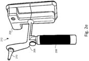
- the means for mounting the apparatus 100 in a fixed position relative to the mobile user device 200 comprises a housing 204 from which the spacing element 206 extends distally.
- a handle 208 and a speculum 210 are coupled to the spacing element 206, the speculum 210 defining an aperture through which human or animal anatomical structures, such as a patient's ear canal, may be examined.
- the speculum 210 is disposed on the distal end of the spacing element 206 and is placed in a patient's ear canal during operation of the apparatus 100. This provides a fixed separation between the object 102 (ear canal) and the first optical element 104.
- the gap 212 is sufficiently large for tool access to the ear canal through the speculum 210, suitable for medical procedures such as micro-suction.
- the apparatus 100 further comprises a mirror arrangement 220 comprising a plurality of mirrors 222 to divert the optical path 218 away from and then towards an axis extending between the first optical element 104 and the final image plane 116. Accordingly, the optical path 218 is longer than the distance between the first optical element 104 and the final image plane 116.
- the plurality of mirrors 222 is preferably a plurality of plane mirrors, for example of about 10 or 12.5mm diameter.
- An aperture of the camera 202 is shown supported in the final image plane 116 in Figure 2a . In one example corresponding to Figures 2a , 2b and 2e , the bounding dimensions of the housing 204 are approximately 80 mm ⁇ 30 mm ⁇ 170 mm.
- the plurality of mirrors 222 may divert the optical path 218 to a plane substantially parallel and proximate to a distal surface (that is the rear surface) of the mobile user device 200.
- a number of other folding arrangements exist, for example a further arrangement is shown in Figure 2d .
- the bounding dimensions of the housing 204 are approximately 20 mm x 50 mm x 120 mm.
- the performance of the achromatic doublets 300, 302 is diffraction limited provided the apparatus 100 has field angles less than around 5 degrees, meaning other common forms of aberrations are reduced, such as spherical aberrations, coma and astigmatism.
- the achromatic doublets 300, 302 may be non-identical, wherein their focal lengths (equivalent to the front and rear focal lengths of the first optical element 104 respectively) are different according to the respective distances of the object 102 and the intermediate image plane 110 from the first optical element 104.
- the first optical element 104 further comprises an aperture stop 310 disposed in between the achromatic doublets 300, 302.
- the aperture stop 310 effects a reduction in the diameter of the entrance pupil of the apparatus 100, wherein the entrance pupil is the smallest optical aperture in the apparatus 100 along the optical path 118. This has the effect of increasing the f-number of the apparatus 100, i.e. the ratio of its focal length to the diameter of the entrance pupil.
- the depth of field in the final image 114 is reduced as a result of magnification. To compensate, greater depth of field is achieved by increasing the f-number.
- the diameter of the aperture stop 310 may be adjustable between a plurality of different sizes.
- the distal 300 and proximal 302 achromatic doublets both have an effective focal length of 100-150 mm and are separated from each other by a gap of 1 mm.
- the aperture stop 310 has an aperture diameter of 6.3 mm.
- the third optical element 120 has an effective focal length of 30 mm and is disposed around 148 mm proximally along the optical path 118 from the proximal achromatic doublet 302.
- the second optical element 112 has an optical power of 12.5 dioptres, and is disposed around 30 mm proximally along the optical path 118 from the third optical element 120 and 1 mm distally along the optical path 118 from the final image plane 116.
- the plane of closest focus exists around 147 mm distally from the distal achromatic doublet 300 and 5 mm from the distal end of the speculum 210; at the plane of closest focus the depth of field is 2 mm and the f-number is 3.
- the plane of furthest focus exists 17 mm distally from the plane of closest focus; at the plane of furthest focus the depth of field is 2.6 mm.
- the optical elements 104, 112, 120 in this example are of diameter 12.5 mm.
- the optical properties of the apparatus 100 can be designed to match the particular optics of a particular mobile user device. This allows the quality of the final image 114 to be tuned appropriately, especially with reference to depth of field and focus range.
- the aperture stop 310 has an aperture diameter of 3 mm and the optical elements 104, 112, 120 have a diameter of 8 mm.
- the plane of closest focus exists 5 mm from the distal end of the speculum 210, and the plane of furthest focus exists 16.8 mm distally from the plane of closest focus.
- the depths of field at the plane of closest and furthest focus are, respectively, 7.7 mm and 9.6 mm.
- the f-number at the plane of closest focus is 6.3.
- the apparatus 100 further comprises a lighting arrangement 400 according to a preferred embodiment which will now be described.
- the lighting arrangement 400 comprises a powered light source 410 and an optical arrangement 420 configured to guide light from the powered light source 410 towards the object 102.
- the lighting arrangement 400 is mounted to the apparatus 100, for example in the speculum (see Figure 4a ) or substantially adjacent to the mobile user device 200 (see Figure 4b ).
- the powered light source 410 is provided by the mobile user device 200; otherwise, the powered light source 410 is a plurality of white light LEDs.
- the optical arrangement 420 is a collimator for collimating the light emitted from the powered light source 410. Directing additional light to the object 102 in this way increases the illumination of the object 102 in the final image 114, providing good image quality despite parts of the apparatus 100 which may reduce the available light, such as the aperture stop 310.
- the lighting arrangement 400 further comprises electronic circuitry 502 for controlling the powered light source 410, and means for attaching the powered light source 410 and electronic circuitry 502 to the apparatus 100 including positioning internal to parts mentioned above.
- the lighting arrangement 400 further comprises a power source 504 for powering the light source 410, and electronic circuitry 506 for controlling the power source, the power source 504 preferably being a rechargeable lithium-ion battery.
- the apparatus 100 comprises a charging stand
- the lighting arrangement 400 is disposed in the speculum 210.
- the powered light source 410 comprises a ring of white light LEDs disposed on a circular printed circuit board extending around a circumference of the speculum 210.
- the optical arrangement 420 extends around a section of the internal contour of the speculum 210 and is coupled to the powered light source 410 to direct light along the length of the speculum 210 towards the object 102.
- Electronic circuitry 502 and a user-operable button 510 for activating the powered light source 410 are disposed in the spacing element 206.
- the power source 504 and its associated circuitry 506 are disposed in the handle 208, providing a counterweight to the mobile user device 200.
- the skilled person will appreciate that other arrangements of the light source and its associated power source may be provided.
- a charging stand 520 is configured to receive the handle 208 of the apparatus 100 in order to charge the power source 504.
- the charging stand 520 comprises a charging stand cover 522 and a cabling 526 for connection to an external power supply, wherein the cabling 526 is coupled to the charging stand 520 via a cable retraction system 528 for biasing mechanically the cabling 526 towards the cover 522.
- the cabling retraction system 528 may comprise a plurality of springs and pulleys.
- Electronic circuitry 524 for controlling the charging of the power source 504 is disposed within the charging stand 520. The charging stand 520 therefore provides a means for charging the power source 504 of the apparatus 100.
- the optical elements 104, 112, 120 may be further configured to provide a stereoscopic final image 114, for example via one or more arrangements of mirrors, lenses and/or prisms.
- the camera 202 may be a stereo camera and the mobile user device 200 may comprise built-in hardware for displaying such stereoscopic images, for example an autostereoscopic screen.
- the mobile user device 200 may be coupled to suitable external viewing hardware for the user, such as binocular spectacles.
- this allows the user to view dual 2D images of the object 102, providing depth perception.
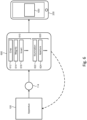
- the application 600 receives the final image 114 in a digital format via one or more image sensors of the camera 202 of the mobile user device 200.
- the application 600 is configured to perform any number of a selection of operations 610 on the image to produce an output image 630.
- the application 600 displays the output image 630 on a screen.
- the application 600 is operable to effect configuration changes in the apparatus 100 using any number of a selection of configuration controls 620.
- the application 600 therefore allows for further digital image enhancement and can be used to optimally display the image 114 of the object 102 for the user.
- the operations 610 include cropping 612, digital magnification 614 and/or real-time image inversion 616.
- Cropping 612 and digital magnification 614 allow the area of interest in the image 114 to be maximised on the screen.
- the magnification 614 can over-zoom the image, i.e. enlarge it beyond a one-to-one mapping between sensor pixels in the camera 202 and screen pixels.
- the optical elements of the apparatus 100 may be configured such that the final image shows an inverted version of the object 102.
- Real-time image inversion 616 allows for this misrepresentation to be corrected.
- the configuration controls 620 include controlling the illumination 622 of the object 102 and the aperture 624 of the optics in the apparatus 100.
- the illumination control 622 communicates with the lighting arrangement 400 via the electronic circuitry 502, 506, for example to alter the intensity, frequency or beam width of the powered light source 410.
- the aperture control 624 adjusts the diameter of one or more adjustable apertures present in the apparatus 100, such as the aperture stop 310 or internal apertures of the camera 202 of the mobile user device 200.
- the skilled person will appreciate that other adjustable elements of the apparatus 100 may be controlled by the application 600 by way of appropriate electro-mechanical communication. Equally, the application may be implemented without configuration controls 620.
- magnification may be implemented with optical elements other than lenses, such as mirrors and/or prisms.
- Optical elements including lenses, mirrors and prisms
- Optical elements of a sufficient quality are used such that the optical performance of the apparatus 100 is assumed to be diffraction-limited. Effects such as field curvature and geometric distortions are not of importance provided sufficiently small field angles are used, as described above.
- the apparatus 100 may be used for a range of other medical examination procedures other than that of the ear canal.
- the apparatus 100 may be used to inspect the nose, throat and mouth, including for assisting with dental procedures.
- the apparatus 100 may also be used for external examination, such as that of the eye or skin surface, for which specialised attachments such as restraints or supports may be required.
- different bodies for defining an aperture may be provided at the distal end of the spacing element.
- a speculum designed for use in a patient's mouth or a body that defines an aperture through which the surface of a patient's skin may be inspected are envisaged.
- the apparatus can be used equally for veterinary as well as for human medical applications.
- the apparatus 100 as described may equally be used for a range of applications in other industries. These may include but are not limited to manufacturing quality control, inspecting electronic circuitry and examining items for forensic purposes.
- the apparatus 100 can be used for detecting surface defects such as cracks in manufactured materials as part of quality control processes.
- physical and biological items in can be examined non-invasively for forensic investigation using the described apparatus 100.
Landscapes
- Health & Medical Sciences (AREA)
- Life Sciences & Earth Sciences (AREA)
- Surgery (AREA)
- Physics & Mathematics (AREA)
- Optics & Photonics (AREA)
- Engineering & Computer Science (AREA)
- Biomedical Technology (AREA)
- Veterinary Medicine (AREA)
- Pathology (AREA)
- Radiology & Medical Imaging (AREA)
- Biophysics (AREA)
- Nuclear Medicine, Radiotherapy & Molecular Imaging (AREA)
- Public Health (AREA)
- Heart & Thoracic Surgery (AREA)
- Medical Informatics (AREA)
- Molecular Biology (AREA)
- Animal Behavior & Ethology (AREA)
- General Health & Medical Sciences (AREA)
- General Physics & Mathematics (AREA)
- Astronomy & Astrophysics (AREA)
- Microelectronics & Electronic Packaging (AREA)
- Signal Processing (AREA)
- Endoscopes (AREA)
- Lenses (AREA)
Claims (15)
- Vorrichtung (100) zum Erzielen einer Vergrößerung eines Objekts (102) für ein Gerät mit einer Kamera, wobei die Vorrichtung Folgendes umfasst:ein erstes optisches Element (104), das an einer ersten Stelle angeordnet ist, um ein Bild (108) des Objekts in einer Zwischenbildebene (110) zu liefern;und ein zweites optisches Element (112), das an einer zweiten Stelle angeordnet ist, um das Zwischenbild (108) optisch zu vergrößern und ein endgültiges Bild (114) in einer endgültigen Bildebene (116) zu erzeugen;Mittel zum Montieren der Vorrichtung in einer festen Position relativ zu dem Gerät, so dass eine Kamerablende des Geräts in der endgültigen Bildebene gehalten wird;ein Abstandselement (206) zum Halten des ersten optischen Elements in einem festen Abstand zu dem Objekt;wobei die Zwischenbildebene und das zweite optische Element entlang eines optischen Pfads (118) angeordnet sind, der sich zwischen dem ersten optischen Element und der endgültigen Bildebene erstreckt;wobei das zweite optische Element auf dem optischen Pfad zwischen der Zwischenbildebene und der endgültigen Bildebene angeordnet ist;dadurch gekennzeichnet, dass ein erster Abstand entlang des optischen Pfads von der Zwischenbildebene zur endgültigen Bildebene erheblich kleiner ist als ein zweiter Abstand entlang des optischen Pfads vom ersten optischen Element zur Zwischenbildebene.
- Vorrichtung (100) nach Anspruch 1, wobei das Gerät mit einer Kamera ein mobiles Benutzergerät umfasst.
- Vorrichtung (100) nach Anspruch 1 oder 2, die ferner Folgendes umfasst:einen Körper zum Definieren einer Öffnung, durch die ein Objekt, optional eine menschliche oder tierische anatomische Struktur, untersucht wird;wobei der Körper vorzugsweise ein Spekulum zum Platzieren im Gehörgang eines Patienten ist;wobei die Vorrichtung bevorzugter ein Otoskop umfasst.
- Vorrichtung (100) nach Anspruch 3, wobei das Spekulum am distalen Ende des Abstandselements (206) angeordnet ist, und wobei das Abstandselement zum Erzeugen eines Spalts für Zugang für ein Werkzeug zum Gehörgang durch das Spekulum konfiguriert ist.
- Vorrichtung (100) nach einem vorherigen Anspruch, die ferner Folgendes umfasst:
ein drittes optisches Element (120), das auf dem optischen Pfad (118) in der Zwischenbildebene (110) angeordnet ist, wobei:das dritte optische Element das gesamte Bild (108) in der Zwischenbildebene enthält; unddas dritte optische Element so angeordnet ist, dass das erste optische Element (104) und das zweite optische Element (112) in konjugierten Ebenen liegen. - Vorrichtung (100) nach einem vorherigen Anspruch, wobei mindestens ein, vorzugsweise jedes, optische(s) Element eine Linse umfasst.
- Vorrichtung (100) nach einem vorherigen Anspruch, wobei das erste optische Element (104) zwei Dubletten (300, 302) umfasst.
- Vorrichtung (100) nach einem vorherigen Anspruch, die ferner Folgendes umfasst:
eine Aperturblende (310), die auf dem optischen Pfad (118) angeordnet ist, wobei die Aperturblende eine Verringerung des Durchmessers der Eintrittspupille der Vorrichtung bewirkt, wobei das erste optische Element (104) optional zwei Dubletten (300, 302) umfasst und die Aperturblende zwischen den beiden Dubletten angeordnet ist. - Vorrichtung (100) nach einem vorherigen Anspruch, die ferner Folgendes umfasst:
eine Spiegelanordnung (220), die mehrere Spiegel (222) umfasst, um den optischen Pfad (118) von einer sich zwischen dem ersten optischen Element (104) und der endgültigen Bildebene (116) erstreckenden Achse weg und dann zu ihr hin umzulenken, so dass der optische Pfad länger ist als der Abstand zwischen dem ersten optischen Element und der endgültigen Bildebene. - Vorrichtung (100) nach Anspruch 9, wobei die mehreren Spiegel (222) den optischen Pfad (118) in eine Ebene umlenken, die im Wesentlichen parallel zu und nahe an einer distalen Oberfläche des Geräts liegt.
- Vorrichtung (100) nach einem vorherigen Anspruch, wobei das erste optische Element (104) achromatisch ist; und/oder wobei die vordere Brennweite des ersten optischen Elements nicht weniger als etwa 80 mm, vorzugsweise nicht weniger als 100 mm und/oder nicht mehr als etwa 180 mm, vorzugsweise nicht mehr als 150 mm beträgt.
- Vorrichtung (100) nach einem vorherigen Anspruch, wobei die Brechkraft des zweiten optischen Elements (112) nicht weniger als etwa 3 Dioptrien, vorzugsweise nicht weniger als 5 Dioptrien und/oder nicht mehr als etwa 25 Dioptrien, vorzugsweise nicht mehr als 23 Dioptrien beträgt; und/oder wobei der optische Vergrößerungsfaktor der Vorrichtung nicht weniger als etwa 8, vorzugsweise nicht weniger als 11 beträgt.
- Vorrichtung (100) nach einem vorherigen Anspruch, die ferner Folgendes umfasst:
eine Beleuchtungsanordnung (400) mit einer gespeisten Lichtquelle (410), vorzugsweise mehreren Weißlicht-LEDs. - Vorrichtung (100) nach Anspruch 13, die ferner Folgendes umfasst:eine optische Anordnung (420), die zum Leiten von Licht von der gespeisten Lichtquelle (410) zu dem Objekt konfiguriert ist;wobei die Beleuchtungsanordnung (400) ferner optional Folgendes umfasst:eine elektronische Schaltung zum Steuern der gespeisten Lichtquelle; undMittel zum Anbringen der gespeisten Lichtquelle und der elektronischen Schaltung an dem Abstandselement (206) ;wobei die optische Anordnung einen Kollimator umfasst.
- Vorrichtung (100) nach Anspruch 13 oder 14, die ferner Folgendes umfasst:eine Stromquelle (504) zum Speisen der Lichtquelle (410), vorzugsweise eine wiederaufladbare Lithium-Ionen-Batterie; undeine elektronische Schaltung zum Steuern der Stromquelle;wobei die Vorrichtung vorzugsweise ferner einen Griff (208) umfasst, und wobei die Stromquelle und die elektronische Schaltung zum Steuern der Stromquelle in dem Griff angeordnet sind.
Priority Applications (1)
| Application Number | Priority Date | Filing Date | Title |
|---|---|---|---|
| EP24189020.1A EP4424229A3 (de) | 2019-11-19 | 2020-11-12 | Optische vorrichtung |
Applications Claiming Priority (3)
| Application Number | Priority Date | Filing Date | Title |
|---|---|---|---|
| GB1916848.3A GB2586289B (en) | 2019-11-19 | 2019-11-19 | Optical apparatus |
| US16/823,657 US10898069B1 (en) | 2019-11-19 | 2020-03-19 | Optical apparatus |
| PCT/GB2020/052887 WO2021099764A1 (en) | 2019-11-19 | 2020-11-12 | Optical apparatus |
Related Child Applications (2)
| Application Number | Title | Priority Date | Filing Date |
|---|---|---|---|
| EP24189020.1A Division EP4424229A3 (de) | 2019-11-19 | 2020-11-12 | Optische vorrichtung |
| EP24189020.1A Division-Into EP4424229A3 (de) | 2019-11-19 | 2020-11-12 | Optische vorrichtung |
Publications (2)
| Publication Number | Publication Date |
|---|---|
| EP4061196A1 EP4061196A1 (de) | 2022-09-28 |
| EP4061196B1 true EP4061196B1 (de) | 2024-09-18 |
Family
ID=69063416
Family Applications (2)
| Application Number | Title | Priority Date | Filing Date |
|---|---|---|---|
| EP24189020.1A Pending EP4424229A3 (de) | 2019-11-19 | 2020-11-12 | Optische vorrichtung |
| EP20811060.1A Active EP4061196B1 (de) | 2019-11-19 | 2020-11-12 | Optische vorrichtung |
Family Applications Before (1)
| Application Number | Title | Priority Date | Filing Date |
|---|---|---|---|
| EP24189020.1A Pending EP4424229A3 (de) | 2019-11-19 | 2020-11-12 | Optische vorrichtung |
Country Status (6)
| Country | Link |
|---|---|
| US (2) | US10898069B1 (de) |
| EP (2) | EP4424229A3 (de) |
| JP (2) | JP7653433B2 (de) |
| CN (2) | CN114945309B (de) |
| GB (1) | GB2586289B (de) |
| WO (1) | WO2021099764A1 (de) |
Families Citing this family (3)
| Publication number | Priority date | Publication date | Assignee | Title |
|---|---|---|---|---|
| GB2586289B (en) * | 2019-11-19 | 2022-03-16 | Tympa Health Tech Ltd | Optical apparatus |
| US20240036297A1 (en) * | 2022-07-29 | 2024-02-01 | Welch Allyn, Inc. | Optical axis compensator for manually guided visual examination with vision aid |
| WO2025181495A1 (en) | 2024-02-29 | 2025-09-04 | Tympa Health Technologies Limited | Image analysis system for otoscopy images |
Family Cites Families (31)
| Publication number | Priority date | Publication date | Assignee | Title |
|---|---|---|---|---|
| US1896861A (en) * | 1931-05-04 | 1933-02-07 | William J Cameron | Illuminated telescope for instruments |
| US2485766A (en) * | 1944-02-15 | 1949-10-25 | Winifred H Parcher | Otoscope or the like |
| DE1797250A1 (de) * | 1968-09-04 | 1971-08-05 | Rotter Johann Dr | Optische Einrichtung mit wenigstens einem abbildenden optischen Glied zur Reproduktion von Vorlagen beliebiger Groesse und zur vergroesserten Betrachtung kleiner Vorlagen |
| US5727236A (en) * | 1994-06-30 | 1998-03-10 | Frazier; James A. | Wide angle, deep field, close focusing optical system |
| US5501652A (en) * | 1994-09-15 | 1996-03-26 | Woods; William A. | Self-examination otoscope |
| DE19804234C1 (de) * | 1998-02-04 | 1999-11-04 | Storz Karl Gmbh & Co | Endoskop, insbesondere Video-Endoskop |
| JP2002034916A (ja) * | 2000-07-24 | 2002-02-05 | Tomio Fujita | 耳腔内視鏡 |
| FR2900741B1 (fr) * | 2006-05-05 | 2008-07-18 | Mauna Kea Technologies Soc Par | Tete optique miniaturisee a haute resolution spatiale et haute sensibilite, notamment pour l'imagerie de fluorescence confocale fibree |
| US20120245422A1 (en) * | 2011-03-21 | 2012-09-27 | Hasbun William M | Otoscope attachment to be used in conjunction with a smart phone and a method for its use |
| US20130063699A1 (en) * | 2011-09-09 | 2013-03-14 | Welch Allyn, Inc. | Ocular Error Detection |
| US8944596B2 (en) * | 2011-11-09 | 2015-02-03 | Welch Allyn, Inc. | Digital-based medical devices |
| US9565996B2 (en) * | 2013-01-18 | 2017-02-14 | Ricoh Company, Ltd. | Plenoptic otoscope |
| US10092175B2 (en) * | 2014-02-12 | 2018-10-09 | Welch Allyn, Inc. | Eye viewing device enabled for performing ear examinations and adapter |
| US9479686B2 (en) * | 2014-02-19 | 2016-10-25 | Melvyn H Kreitzer | Zoom lens optical system |
| US9392933B2 (en) * | 2014-03-06 | 2016-07-19 | Ricoh Company, Ltd. | Otoscope illumination |
| BR112016022204B1 (pt) * | 2014-03-24 | 2022-05-24 | Baylis Medical Company Inc | Aparelho médico para comunicação por fluido |
| JPWO2016056465A1 (ja) * | 2014-10-09 | 2017-07-20 | オリンパス株式会社 | 結像光学系、照明装置および顕微鏡装置 |
| JPWO2016056657A1 (ja) * | 2014-10-09 | 2017-07-27 | オリンパス株式会社 | 結像光学系、照明装置および観察装置 |
| US20160249805A1 (en) * | 2015-02-27 | 2016-09-01 | Welch Allyn, Inc. | Auxiliary flash assembly for a medical instrument |
| US10105051B2 (en) * | 2015-03-22 | 2018-10-23 | Spect Inc. | System and method for a portable eye examination camera |
| US10058247B2 (en) * | 2015-05-20 | 2018-08-28 | Comprehensive Telemedicine | Multipurpose diagnostic examination apparatus and system |
| WO2016193984A1 (en) * | 2015-06-05 | 2016-12-08 | Fresh Pond Ventures Llc | Medical optical examination instrument |
| DE102016106518A1 (de) * | 2016-04-08 | 2017-10-12 | Henke-Sass, Wolf Gmbh | Optiksystem für ein Endoskop |
| US11096627B2 (en) * | 2016-04-25 | 2021-08-24 | Welch Allyn, Inc. | Medical examination system enabling interchangeable instrument operating modes |
| DE102016117547A1 (de) * | 2016-09-18 | 2018-03-22 | Leica Camera Ag | Objektiv fester Brennweite und konstanter Baulänge für Autofokusanwendungen |
| US10561309B2 (en) * | 2016-12-21 | 2020-02-18 | Massachusetts Institute Of Technology | Methods and apparatus for imaging and 3D shape reconstruction |
| DE102017101164B4 (de) * | 2017-01-23 | 2023-01-12 | Carl Zeiss Ag | Vorsatzobjektivsystem, Feldeingriffsvorrichtung, Pupilleneingriffsvorrichtung, Vorsatzobjektiv, Objektträger sowie Beleuchtungssystem |
| US10595724B2 (en) * | 2017-08-04 | 2020-03-24 | Ho Wa LAI | Adaptor for an image capture device for fundus photography |
| GB2569325B (en) * | 2017-12-13 | 2020-05-06 | Imperial Innovations Ltd | Ear examination apparatus |
| US10463307B2 (en) * | 2018-01-12 | 2019-11-05 | The Aga Khan University | Anatomical-imaging communication device |
| GB2586289B (en) * | 2019-11-19 | 2022-03-16 | Tympa Health Tech Ltd | Optical apparatus |
-
2019
- 2019-11-19 GB GB1916848.3A patent/GB2586289B/en active Active
-
2020
- 2020-03-19 US US16/823,657 patent/US10898069B1/en active Active
- 2020-11-12 CN CN202080093104.5A patent/CN114945309B/zh active Active
- 2020-11-12 JP JP2022529448A patent/JP7653433B2/ja active Active
- 2020-11-12 CN CN202510721575.0A patent/CN120284176A/zh active Pending
- 2020-11-12 EP EP24189020.1A patent/EP4424229A3/de active Pending
- 2020-11-12 US US17/777,788 patent/US20220409020A1/en active Pending
- 2020-11-12 EP EP20811060.1A patent/EP4061196B1/de active Active
- 2020-11-12 WO PCT/GB2020/052887 patent/WO2021099764A1/en not_active Ceased
-
2025
- 2025-03-14 JP JP2025041040A patent/JP2025083515A/ja active Pending
Also Published As
| Publication number | Publication date |
|---|---|
| WO2021099764A1 (en) | 2021-05-27 |
| US20220409020A1 (en) | 2022-12-29 |
| EP4424229A2 (de) | 2024-09-04 |
| JP2025083515A (ja) | 2025-05-30 |
| CN114945309B (zh) | 2025-06-20 |
| CN120284176A (zh) | 2025-07-11 |
| JP7653433B2 (ja) | 2025-03-28 |
| EP4424229A3 (de) | 2025-02-12 |
| GB2586289B (en) | 2022-03-16 |
| GB2586289A (en) | 2021-02-17 |
| CN114945309A (zh) | 2022-08-26 |
| EP4061196A1 (de) | 2022-09-28 |
| GB201916848D0 (en) | 2020-01-01 |
| JP2023502686A (ja) | 2023-01-25 |
| US10898069B1 (en) | 2021-01-26 |
Similar Documents
| Publication | Publication Date | Title |
|---|---|---|
| CN209611102U (zh) | 适配器和包含适配器的眼底照相系统 | |
| AU771368B2 (en) | Visual aid in the form of telescopic spectacles with an automatic focussing device | |
| US10028651B2 (en) | Surgical visualization systems and displays | |
| US20160248951A1 (en) | Cellscope apparatus and methods for imaging | |
| US6582362B2 (en) | Endoscope system | |
| JP2025083515A (ja) | 光学装置 | |
| US11006833B2 (en) | Medical optical examination instrument | |
| AU2019248022B2 (en) | Medical device, accessories for use therewith, and methods of use | |
| TW201919537A (zh) | 內視鏡系統 | |
| JP2015135511A (ja) | 医療用の光学観察装置のカメラアダプタおよびカメラ/アダプタ複合体 | |
| US20220214552A9 (en) | Medical magnification device | |
| JPWO2017199926A1 (ja) | 内視鏡装置 | |
| US20150223669A1 (en) | Multi-modal medical examining instrument and related method for enabling multiple examination modes | |
| HK40115818A (en) | Optical apparatus | |
| RU2337606C1 (ru) | Оптическая система эндоскопа | |
| HK40080587B (en) | Optical apparatus | |
| HK40080587A (en) | Optical apparatus | |
| WO2019198293A1 (ja) | 顕微鏡システム及び医療用光源装置 | |
| TWI589261B (zh) | 可與手持式行動裝置結合的簡易式耳鏡 | |
| TW201921034A (zh) | 內視鏡系統 | |
| EP4328648A1 (de) | Digitales mikroskop für medizinische eingriffe | |
| CN121587651A (zh) | 一种成像器件 | |
| CN121587650A (zh) | 一种内窥镜 | |
| KR101947781B1 (ko) | 단층 촬영이 가능한 검이경 |
Legal Events
| Date | Code | Title | Description |
|---|---|---|---|
| STAA | Information on the status of an ep patent application or granted ep patent |
Free format text: STATUS: UNKNOWN |
|
| STAA | Information on the status of an ep patent application or granted ep patent |
Free format text: STATUS: THE INTERNATIONAL PUBLICATION HAS BEEN MADE |
|
| PUAI | Public reference made under article 153(3) epc to a published international application that has entered the european phase |
Free format text: ORIGINAL CODE: 0009012 |
|
| STAA | Information on the status of an ep patent application or granted ep patent |
Free format text: STATUS: REQUEST FOR EXAMINATION WAS MADE |
|
| 17P | Request for examination filed |
Effective date: 20220616 |
|
| AK | Designated contracting states |
Kind code of ref document: A1 Designated state(s): AL AT BE BG CH CY CZ DE DK EE ES FI FR GB GR HR HU IE IS IT LI LT LU LV MC MK MT NL NO PL PT RO RS SE SI SK SM TR |
|
| DAV | Request for validation of the european patent (deleted) | ||
| DAX | Request for extension of the european patent (deleted) | ||
| REG | Reference to a national code |
Ref country code: HK Ref legal event code: DE Ref document number: 40080587 Country of ref document: HK |
|
| P01 | Opt-out of the competence of the unified patent court (upc) registered |
Effective date: 20230514 |
|
| GRAP | Despatch of communication of intention to grant a patent |
Free format text: ORIGINAL CODE: EPIDOSNIGR1 |
|
| STAA | Information on the status of an ep patent application or granted ep patent |
Free format text: STATUS: GRANT OF PATENT IS INTENDED |
|
| INTG | Intention to grant announced |
Effective date: 20240416 |
|
| GRAS | Grant fee paid |
Free format text: ORIGINAL CODE: EPIDOSNIGR3 |
|
| GRAA | (expected) grant |
Free format text: ORIGINAL CODE: 0009210 |
|
| STAA | Information on the status of an ep patent application or granted ep patent |
Free format text: STATUS: THE PATENT HAS BEEN GRANTED |
|
| AK | Designated contracting states |
Kind code of ref document: B1 Designated state(s): AL AT BE BG CH CY CZ DE DK EE ES FI FR GB GR HR HU IE IS IT LI LT LU LV MC MK MT NL NO PL PT RO RS SE SI SK SM TR |
|
| REG | Reference to a national code |
Ref country code: GB Ref legal event code: FG4D |
|
| REG | Reference to a national code |
Ref country code: CH Ref legal event code: EP |
|
| REG | Reference to a national code |
Ref country code: IE Ref legal event code: FG4D |
|
| REG | Reference to a national code |
Ref country code: DE Ref legal event code: R096 Ref document number: 602020038038 Country of ref document: DE |
|
| REG | Reference to a national code |
Ref country code: LT Ref legal event code: MG9D |
|
| PG25 | Lapsed in a contracting state [announced via postgrant information from national office to epo] |
Ref country code: NO Free format text: LAPSE BECAUSE OF FAILURE TO SUBMIT A TRANSLATION OF THE DESCRIPTION OR TO PAY THE FEE WITHIN THE PRESCRIBED TIME-LIMIT Effective date: 20241218 |
|
| PG25 | Lapsed in a contracting state [announced via postgrant information from national office to epo] |
Ref country code: GR Free format text: LAPSE BECAUSE OF FAILURE TO SUBMIT A TRANSLATION OF THE DESCRIPTION OR TO PAY THE FEE WITHIN THE PRESCRIBED TIME-LIMIT Effective date: 20241219 Ref country code: FI Free format text: LAPSE BECAUSE OF FAILURE TO SUBMIT A TRANSLATION OF THE DESCRIPTION OR TO PAY THE FEE WITHIN THE PRESCRIBED TIME-LIMIT Effective date: 20240918 |
|
| PG25 | Lapsed in a contracting state [announced via postgrant information from national office to epo] |
Ref country code: BG Free format text: LAPSE BECAUSE OF FAILURE TO SUBMIT A TRANSLATION OF THE DESCRIPTION OR TO PAY THE FEE WITHIN THE PRESCRIBED TIME-LIMIT Effective date: 20240918 |
|
| PG25 | Lapsed in a contracting state [announced via postgrant information from national office to epo] |
Ref country code: LV Free format text: LAPSE BECAUSE OF FAILURE TO SUBMIT A TRANSLATION OF THE DESCRIPTION OR TO PAY THE FEE WITHIN THE PRESCRIBED TIME-LIMIT Effective date: 20240918 |
|
| PG25 | Lapsed in a contracting state [announced via postgrant information from national office to epo] |
Ref country code: HR Free format text: LAPSE BECAUSE OF FAILURE TO SUBMIT A TRANSLATION OF THE DESCRIPTION OR TO PAY THE FEE WITHIN THE PRESCRIBED TIME-LIMIT Effective date: 20240918 |
|
| REG | Reference to a national code |
Ref country code: NL Ref legal event code: MP Effective date: 20240918 |
|
| PG25 | Lapsed in a contracting state [announced via postgrant information from national office to epo] |
Ref country code: RS Free format text: LAPSE BECAUSE OF FAILURE TO SUBMIT A TRANSLATION OF THE DESCRIPTION OR TO PAY THE FEE WITHIN THE PRESCRIBED TIME-LIMIT Effective date: 20241218 |
|
| PG25 | Lapsed in a contracting state [announced via postgrant information from national office to epo] |
Ref country code: RS Free format text: LAPSE BECAUSE OF FAILURE TO SUBMIT A TRANSLATION OF THE DESCRIPTION OR TO PAY THE FEE WITHIN THE PRESCRIBED TIME-LIMIT Effective date: 20241218 Ref country code: NO Free format text: LAPSE BECAUSE OF FAILURE TO SUBMIT A TRANSLATION OF THE DESCRIPTION OR TO PAY THE FEE WITHIN THE PRESCRIBED TIME-LIMIT Effective date: 20241218 Ref country code: LV Free format text: LAPSE BECAUSE OF FAILURE TO SUBMIT A TRANSLATION OF THE DESCRIPTION OR TO PAY THE FEE WITHIN THE PRESCRIBED TIME-LIMIT Effective date: 20240918 Ref country code: HR Free format text: LAPSE BECAUSE OF FAILURE TO SUBMIT A TRANSLATION OF THE DESCRIPTION OR TO PAY THE FEE WITHIN THE PRESCRIBED TIME-LIMIT Effective date: 20240918 Ref country code: GR Free format text: LAPSE BECAUSE OF FAILURE TO SUBMIT A TRANSLATION OF THE DESCRIPTION OR TO PAY THE FEE WITHIN THE PRESCRIBED TIME-LIMIT Effective date: 20241219 Ref country code: FI Free format text: LAPSE BECAUSE OF FAILURE TO SUBMIT A TRANSLATION OF THE DESCRIPTION OR TO PAY THE FEE WITHIN THE PRESCRIBED TIME-LIMIT Effective date: 20240918 Ref country code: BG Free format text: LAPSE BECAUSE OF FAILURE TO SUBMIT A TRANSLATION OF THE DESCRIPTION OR TO PAY THE FEE WITHIN THE PRESCRIBED TIME-LIMIT Effective date: 20240918 |
|
| REG | Reference to a national code |
Ref country code: AT Ref legal event code: MK05 Ref document number: 1723986 Country of ref document: AT Kind code of ref document: T Effective date: 20240918 |
|
| PG25 | Lapsed in a contracting state [announced via postgrant information from national office to epo] |
Ref country code: NL Free format text: LAPSE BECAUSE OF FAILURE TO SUBMIT A TRANSLATION OF THE DESCRIPTION OR TO PAY THE FEE WITHIN THE PRESCRIBED TIME-LIMIT Effective date: 20240918 |
|
| PG25 | Lapsed in a contracting state [announced via postgrant information from national office to epo] |
Ref country code: PT Free format text: LAPSE BECAUSE OF FAILURE TO SUBMIT A TRANSLATION OF THE DESCRIPTION OR TO PAY THE FEE WITHIN THE PRESCRIBED TIME-LIMIT Effective date: 20250120 Ref country code: IS Free format text: LAPSE BECAUSE OF FAILURE TO SUBMIT A TRANSLATION OF THE DESCRIPTION OR TO PAY THE FEE WITHIN THE PRESCRIBED TIME-LIMIT Effective date: 20250118 |
|
| PG25 | Lapsed in a contracting state [announced via postgrant information from national office to epo] |
Ref country code: SM Free format text: LAPSE BECAUSE OF FAILURE TO SUBMIT A TRANSLATION OF THE DESCRIPTION OR TO PAY THE FEE WITHIN THE PRESCRIBED TIME-LIMIT Effective date: 20240918 Ref country code: RO Free format text: LAPSE BECAUSE OF FAILURE TO SUBMIT A TRANSLATION OF THE DESCRIPTION OR TO PAY THE FEE WITHIN THE PRESCRIBED TIME-LIMIT Effective date: 20240918 |
|
| PG25 | Lapsed in a contracting state [announced via postgrant information from national office to epo] |
Ref country code: ES Free format text: LAPSE BECAUSE OF FAILURE TO SUBMIT A TRANSLATION OF THE DESCRIPTION OR TO PAY THE FEE WITHIN THE PRESCRIBED TIME-LIMIT Effective date: 20240918 |
|
| PG25 | Lapsed in a contracting state [announced via postgrant information from national office to epo] |
Ref country code: AT Free format text: LAPSE BECAUSE OF FAILURE TO SUBMIT A TRANSLATION OF THE DESCRIPTION OR TO PAY THE FEE WITHIN THE PRESCRIBED TIME-LIMIT Effective date: 20240918 Ref country code: EE Free format text: LAPSE BECAUSE OF FAILURE TO SUBMIT A TRANSLATION OF THE DESCRIPTION OR TO PAY THE FEE WITHIN THE PRESCRIBED TIME-LIMIT Effective date: 20240918 |
|
| PG25 | Lapsed in a contracting state [announced via postgrant information from national office to epo] |
Ref country code: CZ Free format text: LAPSE BECAUSE OF FAILURE TO SUBMIT A TRANSLATION OF THE DESCRIPTION OR TO PAY THE FEE WITHIN THE PRESCRIBED TIME-LIMIT Effective date: 20240918 Ref country code: PL Free format text: LAPSE BECAUSE OF FAILURE TO SUBMIT A TRANSLATION OF THE DESCRIPTION OR TO PAY THE FEE WITHIN THE PRESCRIBED TIME-LIMIT Effective date: 20240918 |
|
| PG25 | Lapsed in a contracting state [announced via postgrant information from national office to epo] |
Ref country code: IT Free format text: LAPSE BECAUSE OF FAILURE TO SUBMIT A TRANSLATION OF THE DESCRIPTION OR TO PAY THE FEE WITHIN THE PRESCRIBED TIME-LIMIT Effective date: 20240918 Ref country code: SK Free format text: LAPSE BECAUSE OF FAILURE TO SUBMIT A TRANSLATION OF THE DESCRIPTION OR TO PAY THE FEE WITHIN THE PRESCRIBED TIME-LIMIT Effective date: 20240918 |
|
| REG | Reference to a national code |
Ref country code: DE Ref legal event code: R097 Ref document number: 602020038038 Country of ref document: DE |
|
| REG | Reference to a national code |
Ref country code: CH Ref legal event code: PL |
|
| PG25 | Lapsed in a contracting state [announced via postgrant information from national office to epo] |
Ref country code: MC Free format text: LAPSE BECAUSE OF FAILURE TO SUBMIT A TRANSLATION OF THE DESCRIPTION OR TO PAY THE FEE WITHIN THE PRESCRIBED TIME-LIMIT Effective date: 20240918 |
|
| PG25 | Lapsed in a contracting state [announced via postgrant information from national office to epo] |
Ref country code: DK Free format text: LAPSE BECAUSE OF FAILURE TO SUBMIT A TRANSLATION OF THE DESCRIPTION OR TO PAY THE FEE WITHIN THE PRESCRIBED TIME-LIMIT Effective date: 20240918 |
|
| PG25 | Lapsed in a contracting state [announced via postgrant information from national office to epo] |
Ref country code: LU Free format text: LAPSE BECAUSE OF NON-PAYMENT OF DUE FEES Effective date: 20241112 |
|
| REG | Reference to a national code |
Ref country code: CH Ref legal event code: PL |
|
| PG25 | Lapsed in a contracting state [announced via postgrant information from national office to epo] |
Ref country code: CH Free format text: LAPSE BECAUSE OF NON-PAYMENT OF DUE FEES Effective date: 20241130 |
|
| PLBE | No opposition filed within time limit |
Free format text: ORIGINAL CODE: 0009261 |
|
| STAA | Information on the status of an ep patent application or granted ep patent |
Free format text: STATUS: NO OPPOSITION FILED WITHIN TIME LIMIT |
|
| 26N | No opposition filed |
Effective date: 20250619 |
|
| REG | Reference to a national code |
Ref country code: BE Ref legal event code: MM Effective date: 20241130 |
|
| PG25 | Lapsed in a contracting state [announced via postgrant information from national office to epo] |
Ref country code: SE Free format text: LAPSE BECAUSE OF FAILURE TO SUBMIT A TRANSLATION OF THE DESCRIPTION OR TO PAY THE FEE WITHIN THE PRESCRIBED TIME-LIMIT Effective date: 20240918 |
|
| PG25 | Lapsed in a contracting state [announced via postgrant information from national office to epo] |
Ref country code: BE Free format text: LAPSE BECAUSE OF NON-PAYMENT OF DUE FEES Effective date: 20241130 |
|
| PG25 | Lapsed in a contracting state [announced via postgrant information from national office to epo] |
Ref country code: IE Free format text: LAPSE BECAUSE OF NON-PAYMENT OF DUE FEES Effective date: 20241112 |
|
| PGFP | Annual fee paid to national office [announced via postgrant information from national office to epo] |
Ref country code: DE Payment date: 20251114 Year of fee payment: 6 |
|
| PGFP | Annual fee paid to national office [announced via postgrant information from national office to epo] |
Ref country code: GB Payment date: 20251119 Year of fee payment: 6 |
|
| PGFP | Annual fee paid to national office [announced via postgrant information from national office to epo] |
Ref country code: FR Payment date: 20251125 Year of fee payment: 6 |
|
| PG25 | Lapsed in a contracting state [announced via postgrant information from national office to epo] |
Ref country code: HU Free format text: LAPSE BECAUSE OF FAILURE TO SUBMIT A TRANSLATION OF THE DESCRIPTION OR TO PAY THE FEE WITHIN THE PRESCRIBED TIME-LIMIT; INVALID AB INITIO Effective date: 20201112 |
|
| PG25 | Lapsed in a contracting state [announced via postgrant information from national office to epo] |
Ref country code: CY Free format text: LAPSE BECAUSE OF FAILURE TO SUBMIT A TRANSLATION OF THE DESCRIPTION OR TO PAY THE FEE WITHIN THE PRESCRIBED TIME-LIMIT; INVALID AB INITIO Effective date: 20201112 |