EP4060840B1 - Elektrisches einbaugerät - Google Patents
Elektrisches einbaugerät Download PDFInfo
- Publication number
- EP4060840B1 EP4060840B1 EP22162758.1A EP22162758A EP4060840B1 EP 4060840 B1 EP4060840 B1 EP 4060840B1 EP 22162758 A EP22162758 A EP 22162758A EP 4060840 B1 EP4060840 B1 EP 4060840B1
- Authority
- EP
- European Patent Office
- Prior art keywords
- clamping
- main body
- bearing
- return means
- recessable
- Prior art date
- Legal status (The legal status is an assumption and is not a legal conclusion. Google has not performed a legal analysis and makes no representation as to the accuracy of the status listed.)
- Active
Links
Images


Classifications
-
- H—ELECTRICITY
- H02—GENERATION; CONVERSION OR DISTRIBUTION OF ELECTRIC POWER
- H02G—INSTALLATION OF ELECTRIC CABLES OR LINES, OR OF COMBINED OPTICAL AND ELECTRIC CABLES OR LINES
- H02G3/00—Installations of electric cables or lines or protective tubing therefor in or on buildings, equivalent structures or vehicles
- H02G3/02—Details
- H02G3/08—Distribution boxes; Connection or junction boxes
- H02G3/18—Distribution boxes; Connection or junction boxes providing line outlets
- H02G3/20—Ceiling roses or other lighting sets
-
- F—MECHANICAL ENGINEERING; LIGHTING; HEATING; WEAPONS; BLASTING
- F21—LIGHTING
- F21S—NON-PORTABLE LIGHTING DEVICES; SYSTEMS THEREOF; VEHICLE LIGHTING DEVICES SPECIALLY ADAPTED FOR VEHICLE EXTERIORS
- F21S8/00—Lighting devices intended for fixed installation
- F21S8/02—Lighting devices intended for fixed installation of recess-mounted type, e.g. downlighters
- F21S8/026—Lighting devices intended for fixed installation of recess-mounted type, e.g. downlighters intended to be recessed in a ceiling or like overhead structure, e.g. suspended ceiling
-
- F—MECHANICAL ENGINEERING; LIGHTING; HEATING; WEAPONS; BLASTING
- F21—LIGHTING
- F21V—FUNCTIONAL FEATURES OR DETAILS OF LIGHTING DEVICES OR SYSTEMS THEREOF; STRUCTURAL COMBINATIONS OF LIGHTING DEVICES WITH OTHER ARTICLES, NOT OTHERWISE PROVIDED FOR
- F21V21/00—Supporting, suspending, or attaching arrangements for lighting devices; Hand grips
- F21V21/02—Wall, ceiling, or floor bases; Fixing pendants or arms to the bases
- F21V21/04—Recessed bases
- F21V21/041—Mounting arrangements specially adapted for false ceiling panels or partition walls made of plates
- F21V21/042—Mounting arrangements specially adapted for false ceiling panels or partition walls made of plates using clamping means, e.g. for clamping with panel or wall
- F21V21/044—Mounting arrangements specially adapted for false ceiling panels or partition walls made of plates using clamping means, e.g. for clamping with panel or wall with elastically deformable elements, e.g. spring tongues
- F21V21/045—Mounting arrangements specially adapted for false ceiling panels or partition walls made of plates using clamping means, e.g. for clamping with panel or wall with elastically deformable elements, e.g. spring tongues being tensioned by translation of parts, e.g. by pushing or pulling
-
- H—ELECTRICITY
- H02—GENERATION; CONVERSION OR DISTRIBUTION OF ELECTRIC POWER
- H02G—INSTALLATION OF ELECTRIC CABLES OR LINES, OR OF COMBINED OPTICAL AND ELECTRIC CABLES OR LINES
- H02G3/00—Installations of electric cables or lines or protective tubing therefor in or on buildings, equivalent structures or vehicles
- H02G3/02—Details
- H02G3/08—Distribution boxes; Connection or junction boxes
- H02G3/12—Distribution boxes; Connection or junction boxes for flush mounting
- H02G3/123—Distribution boxes; Connection or junction boxes for flush mounting in thin walls
Definitions
- the present invention relates to the field of built-in electrical appliances suitable and intended to be built into a wall such as a cladding wall or false ceiling or any other similar wall and has as its subject a built-in electrical appliance.
- Such a wall has two opposite faces, namely an external face and an internal face, crossed by at least one hole made to the dimensions of the electrical device to be embedded in said hole.
- These built-in electrical appliances comprise a main body, generally cylindrical or truncated cone-shaped, extending along a longitudinal axis and being provided with a bearing face extending laterally outside the main body so as to be able to bear against the external face of the wall in the built-in state of the appliance. They further comprise two helical torsion springs arranged diametrically opposite on either side of said longitudinal axis.
- each spring forms a clamping lug extending outside the main body and another portion of the spring forms a helical winding constituting the active portion of the spring.
- the helical winding of each spring is mounted on an external side of the main body and forms, in addition to its active function of the spring, a kind of articulation allowing the pivoting of the clamping lug about the winding axis. A free end of the spring winding is fixedly held in the external side.
- Each spring is made from a metal rod bent so as to form, in particular, the winding and the clamping tab extending from the latter and ending in a free end.
- the part of the metal rod forming the clamping leg is usually bent into a U shape, with the base of the U forming the free end.
- Each clamping lug also called a clamping arm or lever, can thus be moved by pivoting about the winding axis between a deployed or raised position allowing the passage of the device through the hole in the wall and a folded or lowered position towards the support face in which the free end of each clamping lug is, in the embedded state of the device in said hole, in support, with pressure, on the internal face of said wall.
- the active part of each spring tends to elastically return by force each clamping lug to its lowered or folded position.
- the wall In the recessed state of the device, the wall is thus held in a vice between the support face of the main body extending transversely to the outside and the free ends of the two fixing lugs returned to the lowered or folded position under the restoring force of each spring.
- the two clamping lugs and the pressure exerted by their free ends on the internal face of the wall make it possible to maintain the device embedded in the wall by clamping on the latter.
- the device is thus maintained in the recessed state by clamping the wall between the free ends of its clamping lugs and its support face.
- the installer When installing the built-in electrical appliance, the installer must first raise or extend with his fingers the two clamping tabs on the sides of the main body in order to allow the insertion/embedding of the appliance in the hole in the wall provided for this purpose until the support face of said appliance comes to bear against the external face of said wall, then when the two clamping tabs have passed to the other side of the wall, that is to say on the side of its internal face, they are automatically returned, under the effect of the restoring force exerted by the active part of the springs, to their lowered or folded position and their free ends then come to bear with pressure on, or to be pressed abruptly against, the internal face of the wall.
- each clamping tab is made from a spring and pivots around the winding axis of said spring:
- the clamping legs are difficult to arm, i.e. to move manually to their deployed or raised position, to allow the passage of the device through the hole in the wall.
- the clamping legs due to the significant retaining force, it can injure the installer. Injuries are particularly frequent when removing the device due to a sudden return of said clamping legs to their lowered or folded position and due to the structure of the clamping legs made from a bent metal rod forming the spring.
- some devices include adjustment means of the potentiometer type allowing to adjust, for example, the time delay or the trigger threshold.
- These potentiometers are accessible on the external lateral face of the main body and require to slightly remove the device from the hole in the wall, and possibly to rotate the device about its longitudinal axis, to allow the user to be opposite said potentiometers.
- the clamping tabs can remain hooked and/or damage the wall of the hole and/or prevent the rotation of the device.
- the document US2020/149721A1 relates to a recessed fixture for installing a luminaire in a wall or ceiling opening. It comprises a luminaire housing and two retaining assemblies each having a portion for mating with the luminaire and another portion for resting on a surface supporting the weight of the luminaire such as a ceiling surface.
- Each retaining assembly comprises a body and a spring extending within the body and being coupled at its distal end to a projection-shaped coupling member of the housing.
- the subject of the invention is a device for installing recessed luminaires in a surface, comprising at least one locking element composed of a first part having a first end associated with said surface and a second part having a second end associated with a structure of the luminaire.
- the two parts can rotate relative to each other around a fixed shaft, mounted on the structure, under the action of a torsion spring defined by a pair of spirals and two opposite ends.
- the document AU2011100986A4 relates to a recessed luminaire in a ceiling hole, said luminaire comprising an annular mounting base configured to be recessed into the hole for mounting the luminaire, at least one frame member connected to said base and a biasing element in the form of a double helix spring connected to the frame member by means of an axis passing through both coils of the spring.
- the present invention aims to overcome these drawbacks.
- the built-in electrical appliance is as defined in claim 1.
- clamping legs 2 may also be called or referred to, for example, as clamping arms or levers.
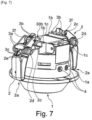
- each clamping tab 2 is associated with one of the return means 3 and is pivotally articulated at its connecting end 2b on said main body 2 around a pivot axis 2c substantially perpendicular to the longitudinal axis X1.
- Each return means 3 is connected to the associated clamping tab 2 and to the main body 1.
- the pivot axis 2c is made from a fixed cylindrical rod, preferably metallic. It is fixed on the main body 1.
- the diameter of the rod is small, that is to say the smallest possible to limit friction (or friction), preferably of the order of 1 mm to 2.5 mm.
- the clamping tab 2 is configured to rotate around such a rod 2c and may comprise for this purpose, at its connecting end 2b, a part forming a hub 2f receiving or crossed by said rod 2c (see in particular the figure 11 ).
- the pivot axis 2c allows the clamping lug 2 to be held on the main body 1.
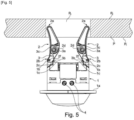
- the bearing face 1a may have a circular or ring shape.
- the bearing face 1a is flat. It preferably extends perpendicular to the longitudinal axis X1.
- the wall P may be a wall intended to be used, in particular, in a building or a structure. It may be of the cladding wall or false ceiling wall type. It may be in the form of a plate, a partition or a panel and be oriented vertically, horizontally or inclined.
- a built-in electrical appliance according to the present invention may be, depending on the application, of the type, for example, a built-in smoke or presence or movement detector, a built-in light or spotlight, or a built-in acoustic speaker.
- a built-in electrical appliance comprises, depending on the application, functional technical parts, for example, electrical, electronic, detection, electrical connection, light or sound, which are known and are not described in the present invention which concerns the support and holding part of the appliance.
- These functional technical parts linked to the application concerned may be contained in the main body 1 or extend outside the latter.
- each return means 3 is supported by the associated clamping tab 2.
- each return means 3 comprises an active part 3a mounted in the associated clamping tab 2 and a connecting end part 3b connected to the main body 2.
- the active part 3a of the return means 3 is understood to mean a part capable of deforming elastically by compression or extension, as opposed to other parts capable and intended to be used for connections or supports.
- each return means 3 can end, opposite its connecting end part 3b, by a holding end part 3c allowing its fixing or holding in the clamping tab 2 which can comprise for this purpose at least one housing 2e. More particularly, the active part 3a can then be extended, on the one hand, by the connecting end part 3b and, on the other hand, by its holding end part 3c.
- the main body 1 comprises at least two bearing and sliding edges 1b, preferably of rounded shape, each associated with one of the return means 3.
- the connecting end portion 3b of each return means 3 is connected to the main body 1 by being supported, by sliding contact, on the associated bearing and sliding edge 1b so that, when the clamping tab 2 is moved between its lowered or folded position and its deployed or raised position or vice versa, each connecting end portion 3b slides on the associated bearing and sliding edge 1b by pivoting around the latter.
- each bearing and sliding edge 1b can extend substantially perpendicular to the longitudinal axis X1.
- each support and sliding edge 1b is located near the pivot axis 2c of the clamping tab 2 supporting the return means 3 with which said support edge 1b is associated. This characteristic makes it possible to optimize the clamping and force effects described below.
- each bearing and sliding edge 1b of the main body 1 is associated with a cavity 1c made in the main body 1 at a level located between said bearing and sliding edge 1b and the bearing face 1a so as to allow the connecting end part 3b of each return means 3 to be inserted into the associated cavity 1c during its sliding on the associated bearing and sliding edge 1b and its pivoting around the latter.
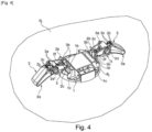
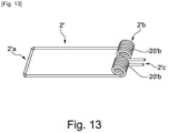
- each return means 3 consists of at least one helical torsion spring 3 ( figures 1 , 2 , 3 , 4 , 5 , 6 , 7 , 8 , 9 And 10 ).
- Each return means 3 may also consist, in a form not shown in the attached figures, of a helical compression or traction spring 3.
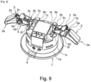
- Each helical torsion spring 3 comprises at least one helical winding 3a forming the active part 3a and extending substantially parallel to the pivot axis 2c of the clamping tab 2 associated with said return means 3.
- each helical torsion spring 3 may preferably comprise two helical windings 3a.
- the two helical windings 3a may extend side by side substantially on the same axis.
- the two helical windings 3a may be arranged on either side of the longitudinal axis of the clamping tab 2.
- each torsion helical spring 3 may comprise a single helical winding 3a.
- the connecting end portion 3b in the case where the torsion helical spring 3 comprises a single helical winding 3a ( figures 9 And 10 ), may be formed by a connecting end 3b connected to said helical winding 3a or, in the case where the helical torsion spring 3 comprises two helical windings 3a ( figures 1 , 2 , 3 , 4 , 5 , 6 , 7 , 8 ), can be formed by two connecting ends 3b, preferably connected to each other, each connected to one of the helical windings 3a.
- Each helical torsion spring 3 may terminate, at its end opposite its connecting end portion 3b, with at least one holding end 3e allowing it to be fixed or held in the clamping tab 2 which may comprise for this purpose at least one housing 2e capable of receiving the or at least one of said holding ends 3e. More particularly, in the case of a helical torsion spring 3 comprising several helical windings 3a, for example two helical windings 3a ( figures 1 , 2 , 3 , 4 , 5 , 6 , 7 , 8 ), each helical torsion spring 3 may comprise several holding ends 3c, for example two holding ends 3c each connected to one of the helical windings 3a. In the case of a helical torsion spring 3 comprising a single winding 3a ( figures 9 And 10 ), this may comprise a single holding end 3c connected to the helical winding 3a.
- each helical winding 3a is extended at one of its ends by a connecting end 3b and at its other end by a holding end 3c. It is also understood that the connecting end portion 3b of each helical torsion spring 3 may be formed by or from one or more connecting ends 3b.
- the connecting end portion 3b may have a U shape. This shape may be achieved, as can be seen in the figures ( figures 1 , 2 , 3 , 4 , 5 , 6 , 7 , 8 ), by the two connecting ends 3b connected together by a connecting branch perpendicular to the latter, this in the case of a helical torsion spring 3 comprising two helical windings 3a.
- each helical winding 3a is mounted around a mandrel 2d ( figures 1 , 2 , 3 , 4 , 5 , 6 , 7 , 9 And 11 ), or in a cylindrical cavity, allowing the active part 3a of the spring 3 (not shown in the attached figures) to be held, integrated in the clamping tab 2 and extending substantially parallel to the pivot axis 2c of the clamping tab 2 associated with said spring 3.
- each clamping tab 2 may comprise a mandrel 2d or a cylindrical cavity common to the two springs 3 or two mandrels or cylindrical cavities extending side by side on the same axis, preferably on either side of the axis of the clamping tab 2.
- each helical torsion spring 3 comprises a single helical winding 3a
- the latter can be arranged on one side or the other of the axis of the clamping tab 2.
- each clamping leg 2 may comprise at least one mandrel 2d or a cylindrical cavity allowing the mounting of a helical spring 3 with two helical windings 3a or with a single helical winding 3a.
- the active part 3a where appropriate the mandrel 2d or the cylindrical cavity, is located substantially in the central or middle part of the associated clamping tab 2 between its free end 2a and its connecting end 2b or between said central or middle part and the connecting end 2b.
- This position of the active part 3a in the clamping tab 2 makes it possible to optimize the clamping and force effects described below.
- each clamping tab 2 is made, at least on the surface, from a material with a low coefficient of friction (or friction).
- This characteristic makes it possible to promote the sliding of the free end 2a of each clamping tab 2 on the internal face P2 of the wall P, in particular to allow or promote the rotation of the electrical device around its longitudinal axis X1 in the embedded state in order to carry out the adjustment or maintenance of the device or its angular positioning.
- the built-in electrical appliance may comprise adjustment means 4, for example, of the potentiometer type, making it possible to adjust, for example, the time delay or the triggering threshold.
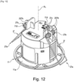
- adjustment means 4 may be accessible on the external lateral face of the main body 1 and require, in the built-in state of the appliance, to slightly remove said appliance from the hole P3 of the wall P, and possibly, to rotate the appliance about its longitudinal axis X, to allow the user to be opposite said adjustment means 4. Thanks to the present invention, such rotation of the appliance is made possible or facilitated without catching or blocking on the wall P or by limiting the latter, unlike a built-in electrical appliance of the prior art such as, for example, that shown in the figure 12 and described subsequently.
- the clamping tabs 2 are made from a plastic material.
- This feature has the effect or advantage of allowing the part to be made with complex shapes to obtain extended or widened contact surfaces at the clamping tabs 2, more particularly their free ends 2a and/or to be able to better configure each clamping tab 2 in order to receive, if necessary, the active part 3a of the return means 3 and/or to obtain a low coefficient of friction (or friction) of the contact or support surfaces such as the external surfaces of the connecting ends 2b intended to come to bear on the support face 1a of the device.
- this has a generally cylindrical or truncated cone shape.
- the two clamping legs 2 can preferably be diametrically opposed on either side of the longitudinal axis X1.
- a built-in electrical appliance according to the present invention in the built-in state in a hole P3 provided for this purpose in a thin wall P ( figure 2 ) or a thick P wall ( figure 3 ), that is to say of greater thickness than that of the thin wall P.
- the clamping tabs 2 are lowered or folded, under the effect of the restoring force exerted by each associated restoring means 3, towards the bearing face 1a of the main body 1 by coming to bear under pressure, by their free end 2a, on the internal face P2 of the wall P.
- Such a built-in electrical appliance according to the present invention makes it possible to obtain a clamping or holding force in the thin wall P identical or almost identical to that obtained in the thick or thicker wall P.
- the two clamping tabs 2' of a built-in electrical appliance of the prior art are not distinct from the return means but are each constituted by a part of a return means 2'b while forming with the latter only a single piece.
- each return means 2'b consists of a helical torsion spring 2'b formed from a rod bent so as to form, on the one hand, two helical windings 20'b extending substantially on the same axis perpendicular to the longitudinal axis X1 of the main body 1' of the device and, on the other hand, a U-shaped part forming one of the two clamping tabs 2' and ending with a free end 2'a coming to bear with pressure on the internal face P2 of a wall P in the embedded state of said device in the latter.
- helical windings 20'b are mounted on the main body 1' by being fixed by a holding end 2'c and by being threaded onto a mandrel 1'd fixed on the main body 1' perpendicular to the longitudinal axis X1.
- Each helical winding 20'b forms, in addition to the active part of the spring 2'b, an articulation on the main body 1' allowing pivoting of the clamping tab 2' about the winding axis.
- the main body 1' comprises a bearing face 1'a capable and intended to come to bear in clamping against the external face P1 of a wall P.
- clamping tabs 2' may damage the hole P3 of the wall P when the appliance is inserted or removed from said hole P3 and cause more or less significant damage to the wall P.
- the restoring force exerted on the clamping tabs 2' is much greater than in the lowered or folded position of said clamping tabs, which makes it difficult to maintain this raised or deployed position or an intermediate position when moving to this raised or deployed position or vice versa and may result in risks of injury to the user.
Landscapes
- Engineering & Computer Science (AREA)
- General Engineering & Computer Science (AREA)
- Architecture (AREA)
- Civil Engineering (AREA)
- Structural Engineering (AREA)
- Clamps And Clips (AREA)
- Snaps, Bayonet Connections, Set Pins, And Snap Rings (AREA)
Claims (10)
- Elektrisches Einbaugerät, welches dafür ausgelegt ist, in ein Loch (P3) eingepasst werden zu können, das durch eine Wand (P) hindurch ausgebildet ist, die zwei gegenüberliegende Seiten aufweist, eine Außenseite (P1) und eine Innenseite (P2), wobei das Gerät umfasst: einen Hauptkörper (1), der sich entlang einer Längsachse (X1) erstreckt und mit einer äußeren Anlageseite (1a) versehen ist, die geeignet und dazu bestimmt ist, im in das Loch (P3) eingepassten Zustand des Gerätes an der Außenseite (P1) zur Anlage zu kommen, mindestens zwei Klemmlaschen (2), die jeweils ein freies Ende (2a) und ein mit dem Hauptkörper (1) verbundenes Verbindungsende (2b) aufweisen, um so die Bewegung jeder Klemmlasche (2) außerhalb des Hauptkörpers (1) zwischen einer angehobenen Position, die das Einsetzen des Gerätes in des Loch (P3) ermöglicht, und einer abgesenkten Position, in der jedes freie Ende (2a) geeignet und dazu bestimmt ist, mit Druck, unter der Einwirkung einer auf die Klemmlaschen ausgeübten Rückstellkraft, an der Innenseite (P2) im eingepassten Zustand des Gerätes zur Anlage zu kommen, um dieses Letztere durch Klemmung der Wand (P) zwischen der Anlageseite (1a) und den freien Enden (2a) zu halten, zu ermöglichen, und Rückstellmittel (3), welche die Rückstellkraft ausüben, die bestrebt ist, diese Letzteren in ihre abgesenkte Position zurückzubewegen, wobei die Rückstellmittel (3) von den Klemmlaschen (2) verschieden sind und jede Klemmlasche (2) einem der Rückstellmittel (3) zugeordnet ist und an ihrem Verbindungsende (2b) am Hauptkörper (1) um eine zur Längsachse (X1) im Wesentlichen senkrechte Schwenkachse (2c) schwenkbar angelenkt ist, wobei jedes Rückstellmittel (3) mit der zugeordneten Klemmlasche (2) und mit dem Hauptkörper (1) verbunden ist, wobei jedes Rückstellmittel (3) von der zugeordneten Klemmlasche (2) gestützt wird und einen aktiven Teil (3a), der in der zugeordneten Klemmlasche (2) angebracht ist, und einen Verbindungsendteil (3b), der mit dem Hauptkörper (1) verbunden ist, umfasst, dadurch gekennzeichnet, dass der Hauptkörper (1) mindestens zwei Anlage- und Gleitränder (1b) umfasst, vorzugsweise von gerundeter Form, die jeweils einem der Rückstellmittel (3) zugeordnet sind, und dadurch, dass der Verbindungsendteil (3b) jedes Rückstellmittels (3) mit dem Hauptkörper (1) verbunden ist, indem er in gleitendem Kontakt am zugeordneten Anlage- und Gleitrand (1b) anliegt, so dass während der Bewegung der Klemmlasche (2) zwischen ihrer abgesenkten Position und ihrer angehobenen Position oder umgekehrt jeder Verbindungsendteil (3b) auf dem zugeordneten Anlage- und Gleitrand (1b) gleitet und dabei um diesen Letzteren schwenkt.
- Elektrisches Einbaugerät nach Anspruch 1, dadurch gekennzeichnet, dass sich der aktive Teil (3a) im Wesentlichen im zentralen oder mittleren Teil der zugeordneten Klemmlasche (2) zwischen ihrem freien Ende (2a) und ihrem Verbindungsende (2b) oder zwischen dem zentralen oder mittleren Teil und dem Verbindungsende (2b) befindet.
- Elektrisches Einbaugerät nach Anspruch 1 oder 2, dadurch gekennzeichnet, dass sich jeder Anlage- und Gleitrand (1b) in der Nähe der Schwenkachse (2c) der Klemmlasche (2) befindet, die das Rückstellmittel (3) stützt, dem der Anlagerand (1b) zugeordnet ist.
- Elektrisches Einbaugerät nach einem der Ansprüche 1 bis 3, dadurch gekennzeichnet, dass jeder Anlage- und Gleitrand (1b) des Hauptkörpers (1) einer Vertiefung (1c) zugeordnet ist, die im Hauptkörper (1) auf einer Höhe ausgebildet ist, die sich zwischen dem Anlage- und Gleitrand (1b) und der Anlageseite (1a) befindet, um zu ermöglichen, dass sich der Verbindungsendteil (3b) jedes Rückstellmittels (3) während seines Gleitens auf dem zugeordneten Anlage- und Gleitrand (1b) und seiner Schwenkung um diesen Letzteren in die zugeordnete Vertiefung (1c) hineinbewegt.
- Elektrisches Einbaugerät nach einem der Ansprüche 1 bis 4, dadurch gekennzeichnet, dass jedes Rückstellmittel (3), das einer Klemmlasche (2) zugeordnet ist, aus mindestens einer Torsions- oder Druck- oder Zugschraubenfeder (3) besteht.
- Elektrisches Einbaugerät nach Anspruch 5, dadurch gekennzeichnet, dass jede Torsionsschraubenfeder (3) mindestens eine schraubenförmige Wicklung umfasst, die den aktiven Teil (3a) bildet und sich im Wesentlichen parallel zur Schwenkachse (2c) der Klemmlasche (2) erstreckt, die dem Rückstellmittel (3) zugeordnet ist.
- Elektrisches Einbaugerät nach Anspruch 6, dadurch gekennzeichnet, dass jede schraubenförmige Wicklung (3a) um einen Dorn (2d) herum oder in einem oder in einer zylindrischen Vertiefung angebracht ist, der bzw. die das Halten des aktiven Teils der Feder ermöglicht, in die Klemmlasche (2) integriert ist und sich im Wesentlichen parallel zur Schwenkachse (4) der Klemmlasche (2) erstreckt, die der Feder (3) zugeordnet ist.
- Elektrisches Einbaugerät nach einem der Ansprüche 1 bis 7, dadurch gekennzeichnet, dass das freie Ende (2a) jeder Klemmlasche (2) wenigstens an der Oberfläche aus einem Material mit einem niedrigen Friktions- oder Reibungskoeffizienten hergestellt ist.
- Elektrisches Einbaugerät nach einem der Ansprüche 1 bis 8, dadurch gekennzeichnet, dass die Klemmlaschen (2) aus einem Kunststoff hergestellt sind.
- Elektrisches Einbaugerät nach einem der Ansprüche 1 bis 9, dadurch gekennzeichnet, dass der Hauptkörper (1) eine im Wesentlichen zylindrische oder kegelstumpfförmige Form aufweist und/oder die Klemmlaschen (2) diametral entgegengesetzt beiderseits der Längsachse (X1) angeordnet sind.
Applications Claiming Priority (1)
| Application Number | Priority Date | Filing Date | Title |
|---|---|---|---|
| FR2102764A FR3120998B1 (fr) | 2021-03-19 | 2021-03-19 | Appareil électrique encastrable |
Publications (2)
| Publication Number | Publication Date |
|---|---|
| EP4060840A1 EP4060840A1 (de) | 2022-09-21 |
| EP4060840B1 true EP4060840B1 (de) | 2025-01-08 |
Family
ID=75746887
Family Applications (1)
| Application Number | Title | Priority Date | Filing Date |
|---|---|---|---|
| EP22162758.1A Active EP4060840B1 (de) | 2021-03-19 | 2022-03-17 | Elektrisches einbaugerät |
Country Status (2)
| Country | Link |
|---|---|
| EP (1) | EP4060840B1 (de) |
| FR (1) | FR3120998B1 (de) |
Families Citing this family (1)
| Publication number | Priority date | Publication date | Assignee | Title |
|---|---|---|---|---|
| CN109489010B (zh) * | 2018-12-20 | 2024-01-26 | 江门市韦尔达照明科技有限公司 | 一种预埋件及面板内嵌设备 |
Family Cites Families (4)
| Publication number | Priority date | Publication date | Assignee | Title |
|---|---|---|---|---|
| ATE474187T1 (de) * | 2006-03-06 | 2010-07-15 | Antares Iluminacion Sa | Vorrichtung zum installieren von einbauleuchten in einer fläche |
| AU2011100986A4 (en) * | 2011-08-09 | 2011-09-08 | Nimbus Lighting Group Limited | Downlight Fixture Mechanism |
| WO2016007018A1 (en) * | 2014-07-11 | 2016-01-14 | Switch Lighting Limited | Improvements in and relating to lighting fixtures |
| US10724717B2 (en) * | 2018-11-08 | 2020-07-28 | Abl Ip Holding Llc | Light fixture installation apparatus and methods |
-
2021
- 2021-03-19 FR FR2102764A patent/FR3120998B1/fr active Active
-
2022
- 2022-03-17 EP EP22162758.1A patent/EP4060840B1/de active Active
Also Published As
| Publication number | Publication date |
|---|---|
| FR3120998A1 (fr) | 2022-09-23 |
| EP4060840A1 (de) | 2022-09-21 |
| FR3120998B1 (fr) | 2023-06-16 |
Similar Documents
| Publication | Publication Date | Title |
|---|---|---|
| EP1150736B1 (de) | Manuelle steuervorrichtung für einen chirurgischen führungsdraht | |
| FR2947961A1 (fr) | Connecteur coaxial coude et son procede d'assemblage. | |
| WO2004032772A2 (fr) | Systeme de fixation a plaque | |
| FR2877150A1 (fr) | Procede de montage d'un connecteur electrique sur un cable coaxial, et un tel connecteur | |
| EP4060840B1 (de) | Elektrisches einbaugerät | |
| EP1722453B1 (de) | Einbaudose | |
| FR2952156A1 (fr) | Collier de fixation sans vis a montage rapide | |
| FR2970532A1 (fr) | Dispositif de fixation pour un revetement isolant de batiment. | |
| WO1991011650A1 (fr) | Dispositif de verrouillage de deux tubes coaxiaux | |
| FR2817931A1 (fr) | Montage d'ecrou | |
| BE1014886A3 (fr) | Guide-cable pour enrouleur de cable d'alimentation | |
| EP2470819B1 (de) | Dämpfungsbrücke | |
| WO2010149279A1 (fr) | Dispositif de fixation a ecrou plastique | |
| EP1538718B1 (de) | Spreizkrallenrückstelleinrichtung | |
| EP1722111B1 (de) | Befestigungselement zur Befestigung eines Metallprofils auf einem Träger | |
| FR3070756B1 (fr) | Accessoire d’aide au reglage de l’alignement d’une roue avant d’une bicyclette par rapport a la potence de son guidon | |
| FR3062526A1 (fr) | Dispositif de connexion d'un conducteur | |
| FR2881287A1 (fr) | Dispositif de fixation etanche d'un cable | |
| FR3012186A1 (fr) | Element de blocage d'au moins deux tubes enfiles l'un dans l'autre, et structure de liaison a tubes telescopiques le comprenant | |
| EP2799641B1 (de) | Zangenregulierbare verankerungsvorrichtung | |
| EP1889668B1 (de) | Verriegelungs- und Entriegelungsvorrichtung für eine Lackierrolle | |
| FR2836511A1 (fr) | Butee a montage rapide pour volet roulant, et volet roulant ainsi equipe | |
| FR3056239A1 (fr) | Dispositif de maintien amovible d’un premier element horizontal sur un second element vertical | |
| FR2589708A1 (fr) | Dispositif de stabilisation de recipients, notamment sur les plans de cuisson | |
| FR3028878A1 (fr) | Poignee de porte |
Legal Events
| Date | Code | Title | Description |
|---|---|---|---|
| PUAI | Public reference made under article 153(3) epc to a published international application that has entered the european phase |
Free format text: ORIGINAL CODE: 0009012 |
|
| STAA | Information on the status of an ep patent application or granted ep patent |
Free format text: STATUS: THE APPLICATION HAS BEEN PUBLISHED |
|
| AK | Designated contracting states |
Kind code of ref document: A1 Designated state(s): AL AT BE BG CH CY CZ DE DK EE ES FI FR GB GR HR HU IE IS IT LI LT LU LV MC MK MT NL NO PL PT RO RS SE SI SK SM TR |
|
| STAA | Information on the status of an ep patent application or granted ep patent |
Free format text: STATUS: REQUEST FOR EXAMINATION WAS MADE |
|
| 17P | Request for examination filed |
Effective date: 20230320 |
|
| RBV | Designated contracting states (corrected) |
Designated state(s): AL AT BE BG CH CY CZ DE DK EE ES FI FR GB GR HR HU IE IS IT LI LT LU LV MC MK MT NL NO PL PT RO RS SE SI SK SM TR |
|
| P01 | Opt-out of the competence of the unified patent court (upc) registered |
Effective date: 20230606 |
|
| GRAP | Despatch of communication of intention to grant a patent |
Free format text: ORIGINAL CODE: EPIDOSNIGR1 |
|
| STAA | Information on the status of an ep patent application or granted ep patent |
Free format text: STATUS: GRANT OF PATENT IS INTENDED |
|
| RIC1 | Information provided on ipc code assigned before grant |
Ipc: H02G 3/12 20060101ALN20241023BHEP Ipc: F21V 21/04 20060101ALN20241023BHEP Ipc: F21S 8/02 20060101ALI20241023BHEP Ipc: H02G 3/20 20060101AFI20241023BHEP |
|
| GRAS | Grant fee paid |
Free format text: ORIGINAL CODE: EPIDOSNIGR3 |
|
| GRAA | (expected) grant |
Free format text: ORIGINAL CODE: 0009210 |
|
| STAA | Information on the status of an ep patent application or granted ep patent |
Free format text: STATUS: THE PATENT HAS BEEN GRANTED |
|
| INTG | Intention to grant announced |
Effective date: 20241114 |
|
| AK | Designated contracting states |
Kind code of ref document: B1 Designated state(s): AL AT BE BG CH CY CZ DE DK EE ES FI FR GB GR HR HU IE IS IT LI LT LU LV MC MK MT NL NO PL PT RO RS SE SI SK SM TR |
|
| REG | Reference to a national code |
Ref country code: GB Ref legal event code: FG4D Free format text: NOT ENGLISH |
|
| REG | Reference to a national code |
Ref country code: CH Ref legal event code: EP |
|
| REG | Reference to a national code |
Ref country code: DE Ref legal event code: R096 Ref document number: 602022009467 Country of ref document: DE |
|
| REG | Reference to a national code |
Ref country code: IE Ref legal event code: FG4D Free format text: LANGUAGE OF EP DOCUMENT: FRENCH |
|
| PGFP | Annual fee paid to national office [announced via postgrant information from national office to epo] |
Ref country code: DE Payment date: 20250327 Year of fee payment: 4 |
|
| PGFP | Annual fee paid to national office [announced via postgrant information from national office to epo] |
Ref country code: AT Payment date: 20250417 Year of fee payment: 4 |
|
| PGFP | Annual fee paid to national office [announced via postgrant information from national office to epo] |
Ref country code: FR Payment date: 20250325 Year of fee payment: 4 |
|
| REG | Reference to a national code |
Ref country code: LT Ref legal event code: MG9D |
|
| REG | Reference to a national code |
Ref country code: NL Ref legal event code: MP Effective date: 20250108 |
|
| REG | Reference to a national code |
Ref country code: AT Ref legal event code: MK05 Ref document number: 1758964 Country of ref document: AT Kind code of ref document: T Effective date: 20250108 |
|
| PG25 | Lapsed in a contracting state [announced via postgrant information from national office to epo] |
Ref country code: NL Free format text: LAPSE BECAUSE OF FAILURE TO SUBMIT A TRANSLATION OF THE DESCRIPTION OR TO PAY THE FEE WITHIN THE PRESCRIBED TIME-LIMIT Effective date: 20250108 |
|
| PG25 | Lapsed in a contracting state [announced via postgrant information from national office to epo] |
Ref country code: RS Free format text: LAPSE BECAUSE OF FAILURE TO SUBMIT A TRANSLATION OF THE DESCRIPTION OR TO PAY THE FEE WITHIN THE PRESCRIBED TIME-LIMIT Effective date: 20250408 |
|
| PG25 | Lapsed in a contracting state [announced via postgrant information from national office to epo] |
Ref country code: PL Free format text: LAPSE BECAUSE OF FAILURE TO SUBMIT A TRANSLATION OF THE DESCRIPTION OR TO PAY THE FEE WITHIN THE PRESCRIBED TIME-LIMIT Effective date: 20250108 |
|
| PG25 | Lapsed in a contracting state [announced via postgrant information from national office to epo] |
Ref country code: ES Free format text: LAPSE BECAUSE OF FAILURE TO SUBMIT A TRANSLATION OF THE DESCRIPTION OR TO PAY THE FEE WITHIN THE PRESCRIBED TIME-LIMIT Effective date: 20250108 |
|
| PG25 | Lapsed in a contracting state [announced via postgrant information from national office to epo] |
Ref country code: NO Free format text: LAPSE BECAUSE OF FAILURE TO SUBMIT A TRANSLATION OF THE DESCRIPTION OR TO PAY THE FEE WITHIN THE PRESCRIBED TIME-LIMIT Effective date: 20250408 Ref country code: IS Free format text: LAPSE BECAUSE OF FAILURE TO SUBMIT A TRANSLATION OF THE DESCRIPTION OR TO PAY THE FEE WITHIN THE PRESCRIBED TIME-LIMIT Effective date: 20250508 |
|
| PG25 | Lapsed in a contracting state [announced via postgrant information from national office to epo] |
Ref country code: HR Free format text: LAPSE BECAUSE OF FAILURE TO SUBMIT A TRANSLATION OF THE DESCRIPTION OR TO PAY THE FEE WITHIN THE PRESCRIBED TIME-LIMIT Effective date: 20250108 |
|
| PG25 | Lapsed in a contracting state [announced via postgrant information from national office to epo] |
Ref country code: LV Free format text: LAPSE BECAUSE OF FAILURE TO SUBMIT A TRANSLATION OF THE DESCRIPTION OR TO PAY THE FEE WITHIN THE PRESCRIBED TIME-LIMIT Effective date: 20250108 Ref country code: PT Free format text: LAPSE BECAUSE OF FAILURE TO SUBMIT A TRANSLATION OF THE DESCRIPTION OR TO PAY THE FEE WITHIN THE PRESCRIBED TIME-LIMIT Effective date: 20250508 |
|
| PG25 | Lapsed in a contracting state [announced via postgrant information from national office to epo] |
Ref country code: BG Free format text: LAPSE BECAUSE OF FAILURE TO SUBMIT A TRANSLATION OF THE DESCRIPTION OR TO PAY THE FEE WITHIN THE PRESCRIBED TIME-LIMIT Effective date: 20250108 Ref country code: GR Free format text: LAPSE BECAUSE OF FAILURE TO SUBMIT A TRANSLATION OF THE DESCRIPTION OR TO PAY THE FEE WITHIN THE PRESCRIBED TIME-LIMIT Effective date: 20250409 |
|
| PGFP | Annual fee paid to national office [announced via postgrant information from national office to epo] |
Ref country code: CH Payment date: 20250401 Year of fee payment: 4 |
|
| PG25 | Lapsed in a contracting state [announced via postgrant information from national office to epo] |
Ref country code: AT Free format text: LAPSE BECAUSE OF FAILURE TO SUBMIT A TRANSLATION OF THE DESCRIPTION OR TO PAY THE FEE WITHIN THE PRESCRIBED TIME-LIMIT Effective date: 20250108 |
|
| PG25 | Lapsed in a contracting state [announced via postgrant information from national office to epo] |
Ref country code: SE Free format text: LAPSE BECAUSE OF FAILURE TO SUBMIT A TRANSLATION OF THE DESCRIPTION OR TO PAY THE FEE WITHIN THE PRESCRIBED TIME-LIMIT Effective date: 20250108 |
|
| PG25 | Lapsed in a contracting state [announced via postgrant information from national office to epo] |
Ref country code: SM Free format text: LAPSE BECAUSE OF FAILURE TO SUBMIT A TRANSLATION OF THE DESCRIPTION OR TO PAY THE FEE WITHIN THE PRESCRIBED TIME-LIMIT Effective date: 20250108 |
|
| REG | Reference to a national code |
Ref country code: DE Ref legal event code: R097 Ref document number: 602022009467 Country of ref document: DE |
|
| PG25 | Lapsed in a contracting state [announced via postgrant information from national office to epo] |
Ref country code: DK Free format text: LAPSE BECAUSE OF FAILURE TO SUBMIT A TRANSLATION OF THE DESCRIPTION OR TO PAY THE FEE WITHIN THE PRESCRIBED TIME-LIMIT Effective date: 20250108 |
|
| PG25 | Lapsed in a contracting state [announced via postgrant information from national office to epo] |
Ref country code: MC Free format text: LAPSE BECAUSE OF FAILURE TO SUBMIT A TRANSLATION OF THE DESCRIPTION OR TO PAY THE FEE WITHIN THE PRESCRIBED TIME-LIMIT Effective date: 20250108 |
|
| PG25 | Lapsed in a contracting state [announced via postgrant information from national office to epo] |
Ref country code: CZ Free format text: LAPSE BECAUSE OF FAILURE TO SUBMIT A TRANSLATION OF THE DESCRIPTION OR TO PAY THE FEE WITHIN THE PRESCRIBED TIME-LIMIT Effective date: 20250108 Ref country code: EE Free format text: LAPSE BECAUSE OF FAILURE TO SUBMIT A TRANSLATION OF THE DESCRIPTION OR TO PAY THE FEE WITHIN THE PRESCRIBED TIME-LIMIT Effective date: 20250108 |
|
| PG25 | Lapsed in a contracting state [announced via postgrant information from national office to epo] |
Ref country code: RO Free format text: LAPSE BECAUSE OF FAILURE TO SUBMIT A TRANSLATION OF THE DESCRIPTION OR TO PAY THE FEE WITHIN THE PRESCRIBED TIME-LIMIT Effective date: 20250108 |
|
| PG25 | Lapsed in a contracting state [announced via postgrant information from national office to epo] |
Ref country code: SK Free format text: LAPSE BECAUSE OF FAILURE TO SUBMIT A TRANSLATION OF THE DESCRIPTION OR TO PAY THE FEE WITHIN THE PRESCRIBED TIME-LIMIT Effective date: 20250108 |
|
| PLBE | No opposition filed within time limit |
Free format text: ORIGINAL CODE: 0009261 |
|
| STAA | Information on the status of an ep patent application or granted ep patent |
Free format text: STATUS: NO OPPOSITION FILED WITHIN TIME LIMIT |
|
| PG25 | Lapsed in a contracting state [announced via postgrant information from national office to epo] |
Ref country code: LU Free format text: LAPSE BECAUSE OF NON-PAYMENT OF DUE FEES Effective date: 20250317 |