EP1538718B1 - Spreizkrallenrückstelleinrichtung - Google Patents
Spreizkrallenrückstelleinrichtung Download PDFInfo
- Publication number
- EP1538718B1 EP1538718B1 EP04360102A EP04360102A EP1538718B1 EP 1538718 B1 EP1538718 B1 EP 1538718B1 EP 04360102 A EP04360102 A EP 04360102A EP 04360102 A EP04360102 A EP 04360102A EP 1538718 B1 EP1538718 B1 EP 1538718B1
- Authority
- EP
- European Patent Office
- Prior art keywords
- grip
- forming
- snap fitting
- assembly
- curved
- Prior art date
- Legal status (The legal status is an assumption and is not a legal conclusion. Google has not performed a legal analysis and makes no representation as to the accuracy of the status listed.)
- Expired - Lifetime
Links
- 210000000078 claw Anatomy 0.000 title description 48
- 230000015556 catabolic process Effects 0.000 description 3
- 238000006731 degradation reaction Methods 0.000 description 3
- 238000005452 bending Methods 0.000 description 2
- 238000003780 insertion Methods 0.000 description 2
- 230000037431 insertion Effects 0.000 description 2
- 208000031968 Cadaver Diseases 0.000 description 1
- 230000032683 aging Effects 0.000 description 1
- 230000000712 assembly Effects 0.000 description 1
- 238000000429 assembly Methods 0.000 description 1
- 230000006378 damage Effects 0.000 description 1
- 230000000694 effects Effects 0.000 description 1
- 230000005489 elastic deformation Effects 0.000 description 1
- 238000009434 installation Methods 0.000 description 1
- 238000004519 manufacturing process Methods 0.000 description 1
- 238000012986 modification Methods 0.000 description 1
- 230000004048 modification Effects 0.000 description 1
- 230000000284 resting effect Effects 0.000 description 1
- 230000035882 stress Effects 0.000 description 1
- 238000006467 substitution reaction Methods 0.000 description 1
- 210000002105 tongue Anatomy 0.000 description 1
Images
Classifications
-
- H—ELECTRICITY
- H02—GENERATION; CONVERSION OR DISTRIBUTION OF ELECTRIC POWER
- H02G—INSTALLATION OF ELECTRIC CABLES OR LINES, OR OF COMBINED OPTICAL AND ELECTRIC CABLES OR LINES
- H02G3/00—Installations of electric cables or lines or protective tubing therefor in or on buildings, equivalent structures or vehicles
- H02G3/02—Details
- H02G3/08—Distribution boxes; Connection or junction boxes
- H02G3/12—Distribution boxes; Connection or junction boxes for flush mounting
- H02G3/121—Distribution boxes; Connection or junction boxes for flush mounting in plain walls
-
- H—ELECTRICITY
- H02—GENERATION; CONVERSION OR DISTRIBUTION OF ELECTRIC POWER
- H02G—INSTALLATION OF ELECTRIC CABLES OR LINES, OR OF COMBINED OPTICAL AND ELECTRIC CABLES OR LINES
- H02G3/00—Installations of electric cables or lines or protective tubing therefor in or on buildings, equivalent structures or vehicles
- H02G3/02—Details
- H02G3/08—Distribution boxes; Connection or junction boxes
- H02G3/12—Distribution boxes; Connection or junction boxes for flush mounting
- H02G3/123—Distribution boxes; Connection or junction boxes for flush mounting in thin walls
Definitions
- the present invention relates to the field of electrical appliances, domestic, semi-recessed, such as sockets, switches, infrared detectors, ... which are fixed in recess boxes via claws and has as an object a device for returning the claws for disassembly.
- the fastening claws of such apparatuses which are intended to be hooked into the corresponding walls of the flush-mounting boxes under the effect of screw tightening tending to rotate these claws towards said walls, are generally recalled in the rest position by means of elastic means such as an elastic band completely surrounding the apparatus and resting on the outer faces of the claws, or again by means of spring devices such as bending spring blades riveted on the claws or by torsion springs acting on said claws.
- the elastic return means have essentially the disadvantage of a very rapid aging causing their destruction, so that they are generally inoperative when disassembly of the equipment must be performed.
- the spring return devices such as blades riveted to the claws, are known in particular by DE-A-38 23 117 and have the disadvantage of providing a relatively complex and expensive solution to the problem.
- Such a device does not allow, however, a quick and easy mounting on an apparatus and may degrade rapidly in case of multiple maneuvers.
- the present invention aims to overcome these drawbacks by proposing a device for rapping claws for disassembly that is simple to assemble inexpensive manufacturing and that is not likely to deteriorate over time.
- claws for disassembly for electrical equipment, domestic, semi-recessed such as sockets, switches, infrared detectors, etc., fixed in recessed boxes by means of claws according to claim 1.
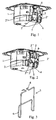
- FIGS. 1 and 2 appended drawings show a semi-recessed apparatus, electrical, domestic, such as a socket or a computer socket 1 provided with claws 2 for fixing in a flush-mounting box, not shown, each claw being provided with teeth 2 ' intended to penetrate the wall of the flush-mounting box and a return device.
- Figures 1 and 2 drawings which represent an apparatus in a side perspective view from below, only a claw 2 is visible. However, in known manner, such equipment is always fixed by means of two diametrically opposed claws and actuated by screws.
- the return device 3 of the claws 2 is essentially, for each claw 2, in the form of a wire spring 3 provided with a first means 4 snap-fitting in a corresponding housing 5 of the apparatus and a second means 6 for snap-fitting on the corresponding claw 2.
- the wire spring forming the return device 3 ( figure 3 ) is advantageously in the form of an integrally folded element comprising a lower part constituting the first snap-fitting means 4, which is in the form of a U-shaped piece whose ends of the flanges are curved and extended in parallel by arms forming the body of the device 3, said arms being bent at their end parallel to the core of the U forming the first snap-fitting means 4 to form the second snap-fitting means 6 which is constituted by curved hooks in the opposite direction of the bent portions of the arms forming the body of the device 3.
- Each housing 5 intended to cooperate for latching with the first latching mounting means 4 is constituted by a recess of the wall of the apparatus 1 delimited by grooves 5 '( figure 2 ) and by a hooking lug 5 "protruding into the housing 5 between the grooves 5 'The holding surface of the hooking lug 5" is advantageously located at a distance from the opposite end of the grooves 5' slightly greater than the length of the arms of the U forming the first snap fit means 4.
- the wire spring forming the device 3 can be snapped into the housing 5 of the body 1 of the apparatus by inserting the wings of the U forming the first snap-fitting means 4 into the grooves 5 'of the housing 5, then by engagement of its core with the latching lug 5 "following an elastic deformation of the entire U at the end of insertion of the first snap-fitting means 4 into the housing 5.
- bent hooks forming the second snap-fitting means 6 on the corresponding claw 2 cooperate with an elongate recess 2 "of the claw 2, the width of which is slightly greater than the curved portion of the hooks 6 extending parallel to the curved portions of the claws.
- the arms forming the body of the device 3 and connecting the first snap-fitting means 4 to the body 1 of the apparatus and the second snap-fitting means 6 to the claw 2 advantageously have a spacing slightly greater than the largest width of the claw 2, which extends between the teeth 2 'and the narrowed portion with the obvious 2 ".
- each claw 2 is held laterally by the devices 3, so that both during fastening operations and during disassembly operations, the claws 2 move perfectly perpendicularly to the corresponding wall of the body 1 of the apparatus.
- the spring forming the device 3 When clamping the actuating screw of the claw 2, the spring forming the device 3 is stretched and biased at the junction of the arms forming the body of the device 3 with the first snap-fitting means 4. Given the relatively large size of the device 3, the resulting bending stress is relatively low, so that the fatigue degradation of said device 3 is almost insignificant. When loosening the actuating screw of the claw 2, the device 3 recalls said claw in its position shown in FIG. figure 1 .
- the invention it is possible to provide a device for returning claws for electrical equipment, domestic semi-recessed mounting in recessed boxes, with great reliability over time and allowing precise guiding of claws both when tightening only when loosening them.
Landscapes
- Engineering & Computer Science (AREA)
- Architecture (AREA)
- Civil Engineering (AREA)
- Structural Engineering (AREA)
- Casings For Electric Apparatus (AREA)
- Management, Administration, Business Operations System, And Electronic Commerce (AREA)
- Crystals, And After-Treatments Of Crystals (AREA)
- Magnetic Ceramics (AREA)
- Electrical Discharge Machining, Electrochemical Machining, And Combined Machining (AREA)
- Holding Or Fastening Of Disk On Rotational Shaft (AREA)
- Clamps And Clips (AREA)
Claims (6)
- Vorrichtung (3) zum Zurückstellen von Krallen (2) an Elektroinstallationsgeräten mit einem Teilgehäuse, wie etwa einer Starkstromsteckdose oder einer Datensteckdose (1), welche mit Spreizkrallen (2) zum Fixieren in einer Einbaudose versehen sind, wobei jede Spreizkralle mit Zähnen (2') versehen ist, die in die Wand der Einbaudose eindringen sollen, und mit einer Rückstellvorrichtung (3), die sich für jede Spreizkralle (2) im Wesentlichen in Form einer Drahtfeder (3) darstellt, welche aus einem einzigen gefalteten Element gebildet ist, dadurch gekennzeichnet, dass die Drahtfeder (3) mit einem ersten Rastmontagemittel (4) in einen entsprechenden Sitz (5) der Einrichtung und einem zweiten Rastmontagemittel (6) an der entsprechenden Spreizkralle (2) versehen ist, wobei diese Drahtfeder (3) einen unteren Abschnitt aufweist, der das erste Rastmontagemittel (4) an dem Gehäuse (1) des Elektroinstallationsgeräts bildet und die Form eines U besitzt, welches einen Steg und Schenkel aufweist, wobei die Schenkelenden umgebogen und parallel zu den Schenkeln durch Arme verlängert sind, die den Körper der Vorrichtung (3) bilden, wobei die Arme an ihren Enden nach innen und parallel zu dem U-Steg, welcher das erste Rastmontagemittel (4) bildet, gebogen sind, um das zweite Rastmontagemittel (6), welches durch Haken gebildet wird, die entgegengesetzt zu dem gebogenen Abschnitt der Arme gebogen sind, an der Spreizkralle (2) zu bilden, das den Körper der Vorrichtung (3) bildet.
- Vorrichtung nach Anspruch 1, dadurch gekennzeichnet, dass jeder Sitz (5), der zum Einrasten mit dem ersten Rastmittel (4) ausgelegt ist, durch eine Aussparung in der Wand des Elektroinstallationsgeräts (1), die von Nuten (5') und durch eine in den Sitz (5) vorspringende Rastnase (5") zwischen den Nuten (5') begrenzt ist, gebildet ist.
- Vorrichtung nach Anspruch 2, dadurch gekennzeichnet, dass die Haltefläche der Rastnase (5") in einem Abstand von dem gegenüberliegenden Ende der Nuten (5') gelegen ist, der etwas größer ist als die Länge der Arme des U, welches das erste Rastmittel (4) bildet.
- Vorrichtung nach Anspruch 1, dadurch gekennzeichnet, dass die gebogenen Haken, die das zweite Rastmittel (6) zum Montieren an der entsprechenden Kralle (2) bilden, mit einer länglichen Aussparung (2") der Kralle (2) zusammenwirken, deren Breite etwas größer ist als der gebogene Abschnitt der Haken (6), der sich parallel zu den gebogenen Abschnitten der Arme erstreckt, die den Körper der Vorrichtung (3) bilden.
- Vorrichtung nach Anspruch 4, dadurch gekennzeichnet, dass die Aussparung (2") sich in vorteilhafter Weise in einen verengten Abschnitt der Kralle (2) erstreckt, entfernt von dem Ende, welches die Zähne (2') aufweist, die sich in die Wände der Einbaudose (2) eingraben sollen, nahe dem mittels Schraube zu betätigenden Ende.
- Vorrichtung nach einem der Ansprüche 1 und 5, dadurch gekennzeichnet, dass die Arme, die den Körper der Vorrichtung (3) bilden und das erste Rastmontagemittel (4) am Gerätegehäuse (1) mit dem zweiten Rastmittel (6) zum Montieren an der Kralle (2) verbinden, einen Abstand aufweisen, der etwas größer ist als die größte Breite der Kralle (2), die sich zwischen den Zähnen (2') und dem die Aussparung (2") umfassenden verengten Abschnitt erstreckt.
Applications Claiming Priority (2)
| Application Number | Priority Date | Filing Date | Title |
|---|---|---|---|
| FR0314261A FR2863412B1 (fr) | 2003-12-04 | 2003-12-04 | Dispositif de rappel des griffes |
| FR0314261 | 2003-12-04 |
Publications (2)
| Publication Number | Publication Date |
|---|---|
| EP1538718A1 EP1538718A1 (de) | 2005-06-08 |
| EP1538718B1 true EP1538718B1 (de) | 2010-07-14 |
Family
ID=34451724
Family Applications (1)
| Application Number | Title | Priority Date | Filing Date |
|---|---|---|---|
| EP04360102A Expired - Lifetime EP1538718B1 (de) | 2003-12-04 | 2004-11-30 | Spreizkrallenrückstelleinrichtung |
Country Status (4)
| Country | Link |
|---|---|
| EP (1) | EP1538718B1 (de) |
| AT (1) | ATE474353T1 (de) |
| DE (1) | DE602004028092D1 (de) |
| FR (1) | FR2863412B1 (de) |
Families Citing this family (4)
| Publication number | Priority date | Publication date | Assignee | Title |
|---|---|---|---|---|
| FR2959882B1 (fr) * | 2010-05-04 | 2014-10-31 | Legrand France | Appareillage electrique encastrable a etancheite amelioree |
| EP3096424B1 (de) * | 2015-05-21 | 2019-02-13 | Simon, S.A.U. | Flexibler klauengriff zum befestigen eines elementes in einer schachtel und mit diesem klauengriff zu befestigendes element |
| FR3105561B1 (fr) * | 2019-12-20 | 2021-12-31 | Legrand France | Boîte électrique en deux parties |
| CN112467642A (zh) * | 2020-11-13 | 2021-03-09 | 江西泉新电气有限公司 | 一种线缆固线器 |
Family Cites Families (1)
| Publication number | Priority date | Publication date | Assignee | Title |
|---|---|---|---|---|
| DE20013233U1 (de) * | 2000-08-01 | 2001-12-13 | GIRA Giersiepen GmbH & Co. KG, 42477 Radevormwald | Elektrisches Installationsgerät |
-
2003
- 2003-12-04 FR FR0314261A patent/FR2863412B1/fr not_active Expired - Fee Related
-
2004
- 2004-11-30 EP EP04360102A patent/EP1538718B1/de not_active Expired - Lifetime
- 2004-11-30 DE DE602004028092T patent/DE602004028092D1/de not_active Expired - Lifetime
- 2004-11-30 AT AT04360102T patent/ATE474353T1/de not_active IP Right Cessation
Also Published As
| Publication number | Publication date |
|---|---|
| FR2863412A1 (fr) | 2005-06-10 |
| DE602004028092D1 (de) | 2010-08-26 |
| EP1538718A1 (de) | 2005-06-08 |
| ATE474353T1 (de) | 2010-07-15 |
| FR2863412B1 (fr) | 2008-07-18 |
Similar Documents
| Publication | Publication Date | Title |
|---|---|---|
| EP3206260A1 (de) | Elektrisches gerät, das über eine druckverbindungsklemme mit einer halteklammer verfügt, die die elastische verformung der kontaktfeder führt und begrenzt | |
| EP1538718B1 (de) | Spreizkrallenrückstelleinrichtung | |
| EP3089295B1 (de) | Elektrische verbindungsvorrichtung zur spannungsausgleichsverbindung von einem kabelrinnenabschnitt mit eines stromkabelabschnitts | |
| EP3598582B1 (de) | Elektrische verbindungsvorrichtung | |
| BE1018556A5 (fr) | Rallonge de griffes de serrage d'elements electriques. | |
| EP1950858B1 (de) | Befestigungsvorrichtung für Installationsgeräte mittels Krallen | |
| EP4060840B1 (de) | Elektrisches einbaugerät | |
| EP1531525B1 (de) | Kabelklemme mit vergrösserter Klemmfläche und damit ausgerüsteter Verbinderblock | |
| FR2770937A1 (fr) | Appareillage electrique a encastrer a fixation par griffes | |
| FR2963488A1 (fr) | Embout multipolaire de connexion electrique | |
| FR3006419A1 (fr) | Luminaire encastrable | |
| EP0370876B1 (de) | Vorrichtung zum Befestigen der Entmagnetisierungsspule eines Fernsehgeräts | |
| EP0698741A1 (de) | Schraube mit einem von einem Käfig umschlossenen Kopf zur Befestigung z.B. in der Öffnung einer Platte | |
| EP0643444A1 (de) | Elektrischer Kontakt mit elastischer Rückstellung | |
| FR2881287A1 (fr) | Dispositif de fixation etanche d'un cable | |
| FR2668863A1 (fr) | Canal pour installations electriques ou similaires ou pour reseaux de distribution en general. | |
| FR3028356A1 (fr) | Borne de connexion electrique a vis imperdable | |
| EP2618034A1 (de) | Träger für schraubenlose Rohrschellen zur Schnellmontage | |
| EP2500981A1 (de) | Elektrische Verbindungsvorrichtung zum Erden von Metallstrukturen | |
| FR2711196A1 (fr) | Ecrou encagé à montage sur un rail ou analogue et assemblage obtenu à l'aide de cet écrou. | |
| EP0680127A2 (de) | Wickelvorrichtung für elektrische Kabel um einem Aggegatgehäuse | |
| FR2796774A1 (fr) | Griffe de prolongement a ressort de verrouillage sur une griffe d'origine de mecanisme electrique | |
| EP1928058A1 (de) | Automatische elektrische Verbindungsklemme | |
| EP1445844B1 (de) | Elektrische Struktur mit einer Befestigungsvorrichtung wenigstens eines Kabels, sowie entsprechende Verschlussinstallation oder Sonnenschutzinstallation | |
| EP3408545B1 (de) | Anordnung zum befestigen und entfernen einer platte zum tragen von kabelbaumklemmvorrichtungen |
Legal Events
| Date | Code | Title | Description |
|---|---|---|---|
| PUAI | Public reference made under article 153(3) epc to a published international application that has entered the european phase |
Free format text: ORIGINAL CODE: 0009012 |
|
| AK | Designated contracting states |
Kind code of ref document: A1 Designated state(s): AT BE BG CH CY CZ DE DK EE ES FI FR GB GR HU IE IS IT LI LU MC NL PL PT RO SE SI SK TR |
|
| AX | Request for extension of the european patent |
Extension state: AL HR LT LV MK YU |
|
| RAP1 | Party data changed (applicant data changed or rights of an application transferred) |
Owner name: HAGER CONTROLS |
|
| 17P | Request for examination filed |
Effective date: 20051012 |
|
| AKX | Designation fees paid |
Designated state(s): AT CH DE LI NL |
|
| 17Q | First examination report despatched |
Effective date: 20090420 |
|
| GRAP | Despatch of communication of intention to grant a patent |
Free format text: ORIGINAL CODE: EPIDOSNIGR1 |
|
| GRAS | Grant fee paid |
Free format text: ORIGINAL CODE: EPIDOSNIGR3 |
|
| GRAA | (expected) grant |
Free format text: ORIGINAL CODE: 0009210 |
|
| AK | Designated contracting states |
Kind code of ref document: B1 Designated state(s): AT CH DE LI NL |
|
| REG | Reference to a national code |
Ref country code: CH Ref legal event code: EP |
|
| REG | Reference to a national code |
Ref country code: CH Ref legal event code: NV Representative=s name: SCHNEIDER FELDMANN AG PATENT- UND MARKENANWAELTE |
|
| REF | Corresponds to: |
Ref document number: 602004028092 Country of ref document: DE Date of ref document: 20100826 Kind code of ref document: P |
|
| REG | Reference to a national code |
Ref country code: NL Ref legal event code: VDEP Effective date: 20100714 |
|
| PG25 | Lapsed in a contracting state [announced via postgrant information from national office to epo] |
Ref country code: AT Free format text: LAPSE BECAUSE OF FAILURE TO SUBMIT A TRANSLATION OF THE DESCRIPTION OR TO PAY THE FEE WITHIN THE PRESCRIBED TIME-LIMIT Effective date: 20100714 Ref country code: NL Free format text: LAPSE BECAUSE OF FAILURE TO SUBMIT A TRANSLATION OF THE DESCRIPTION OR TO PAY THE FEE WITHIN THE PRESCRIBED TIME-LIMIT Effective date: 20100714 |
|
| PLBE | No opposition filed within time limit |
Free format text: ORIGINAL CODE: 0009261 |
|
| STAA | Information on the status of an ep patent application or granted ep patent |
Free format text: STATUS: NO OPPOSITION FILED WITHIN TIME LIMIT |
|
| 26N | No opposition filed |
Effective date: 20110415 |
|
| REG | Reference to a national code |
Ref country code: DE Ref legal event code: R097 Ref document number: 602004028092 Country of ref document: DE Effective date: 20110415 |
|
| REG | Reference to a national code |
Ref country code: CH Ref legal event code: PFA Owner name: HAGER CONTROLS, FR Free format text: FORMER OWNER: HAGER CONTROLS, FR |
|
| PGFP | Annual fee paid to national office [announced via postgrant information from national office to epo] |
Ref country code: DE Payment date: 20221125 Year of fee payment: 19 |
|
| PGFP | Annual fee paid to national office [announced via postgrant information from national office to epo] |
Ref country code: CH Payment date: 20221205 Year of fee payment: 19 |
|
| REG | Reference to a national code |
Ref country code: DE Ref legal event code: R119 Ref document number: 602004028092 Country of ref document: DE |
|
| REG | Reference to a national code |
Ref country code: CH Ref legal event code: PL |
|
| PG25 | Lapsed in a contracting state [announced via postgrant information from national office to epo] |
Ref country code: CH Free format text: LAPSE BECAUSE OF NON-PAYMENT OF DUE FEES Effective date: 20231130 |
|
| PG25 | Lapsed in a contracting state [announced via postgrant information from national office to epo] |
Ref country code: CH Free format text: LAPSE BECAUSE OF NON-PAYMENT OF DUE FEES Effective date: 20231130 |
|
| PG25 | Lapsed in a contracting state [announced via postgrant information from national office to epo] |
Ref country code: DE Free format text: LAPSE BECAUSE OF NON-PAYMENT OF DUE FEES Effective date: 20240601 |
|
| PG25 | Lapsed in a contracting state [announced via postgrant information from national office to epo] |
Ref country code: DE Free format text: LAPSE BECAUSE OF NON-PAYMENT OF DUE FEES Effective date: 20240601 |