EP4059688B1 - Fiber-reinforced composite forming method and fiber-reinforced composite forming apparatus - Google Patents
Fiber-reinforced composite forming method and fiber-reinforced composite forming apparatus Download PDFInfo
- Publication number
- EP4059688B1 EP4059688B1 EP20927548.6A EP20927548A EP4059688B1 EP 4059688 B1 EP4059688 B1 EP 4059688B1 EP 20927548 A EP20927548 A EP 20927548A EP 4059688 B1 EP4059688 B1 EP 4059688B1
- Authority
- EP
- European Patent Office
- Prior art keywords
- fiber
- pressure
- base material
- reinforced composite
- fiber base
- Prior art date
- Legal status (The legal status is an assumption and is not a legal conclusion. Google has not performed a legal analysis and makes no representation as to the accuracy of the status listed.)
- Active
Links
Images





Classifications
-
- B—PERFORMING OPERATIONS; TRANSPORTING
- B29—WORKING OF PLASTICS; WORKING OF SUBSTANCES IN A PLASTIC STATE IN GENERAL
- B29C—SHAPING OR JOINING OF PLASTICS; SHAPING OF MATERIAL IN A PLASTIC STATE, NOT OTHERWISE PROVIDED FOR; AFTER-TREATMENT OF THE SHAPED PRODUCTS, e.g. REPAIRING
- B29C70/00—Shaping composites, i.e. plastics material comprising reinforcements, fillers or preformed parts, e.g. inserts
- B29C70/04—Shaping composites, i.e. plastics material comprising reinforcements, fillers or preformed parts, e.g. inserts comprising reinforcements only, e.g. self-reinforcing plastics
- B29C70/28—Shaping operations therefor
- B29C70/40—Shaping or impregnating by compression not applied
- B29C70/42—Shaping or impregnating by compression not applied for producing articles of definite length, i.e. discrete articles
- B29C70/44—Shaping or impregnating by compression not applied for producing articles of definite length, i.e. discrete articles using isostatic pressure, e.g. pressure difference-moulding, vacuum bag-moulding, autoclave-moulding or expanding rubber-moulding
- B29C70/443—Shaping or impregnating by compression not applied for producing articles of definite length, i.e. discrete articles using isostatic pressure, e.g. pressure difference-moulding, vacuum bag-moulding, autoclave-moulding or expanding rubber-moulding and impregnating by vacuum or injection
-
- B—PERFORMING OPERATIONS; TRANSPORTING
- B29—WORKING OF PLASTICS; WORKING OF SUBSTANCES IN A PLASTIC STATE IN GENERAL
- B29C—SHAPING OR JOINING OF PLASTICS; SHAPING OF MATERIAL IN A PLASTIC STATE, NOT OTHERWISE PROVIDED FOR; AFTER-TREATMENT OF THE SHAPED PRODUCTS, e.g. REPAIRING
- B29C33/00—Moulds or cores; Details thereof or accessories therefor
- B29C33/44—Moulds or cores; Details thereof or accessories therefor with means for, or specially constructed to facilitate, the removal of articles, e.g. of undercut articles
- B29C33/46—Moulds or cores; Details thereof or accessories therefor with means for, or specially constructed to facilitate, the removal of articles, e.g. of undercut articles using fluid pressure
-
- B—PERFORMING OPERATIONS; TRANSPORTING
- B29—WORKING OF PLASTICS; WORKING OF SUBSTANCES IN A PLASTIC STATE IN GENERAL
- B29C—SHAPING OR JOINING OF PLASTICS; SHAPING OF MATERIAL IN A PLASTIC STATE, NOT OTHERWISE PROVIDED FOR; AFTER-TREATMENT OF THE SHAPED PRODUCTS, e.g. REPAIRING
- B29C33/00—Moulds or cores; Details thereof or accessories therefor
- B29C33/44—Moulds or cores; Details thereof or accessories therefor with means for, or specially constructed to facilitate, the removal of articles, e.g. of undercut articles
- B29C33/48—Moulds or cores; Details thereof or accessories therefor with means for, or specially constructed to facilitate, the removal of articles, e.g. of undercut articles with means for collapsing or disassembling
- B29C33/50—Moulds or cores; Details thereof or accessories therefor with means for, or specially constructed to facilitate, the removal of articles, e.g. of undercut articles with means for collapsing or disassembling elastic or flexible
- B29C33/505—Moulds or cores; Details thereof or accessories therefor with means for, or specially constructed to facilitate, the removal of articles, e.g. of undercut articles with means for collapsing or disassembling elastic or flexible cores or mandrels, e.g. inflatable
-
- B—PERFORMING OPERATIONS; TRANSPORTING
- B29—WORKING OF PLASTICS; WORKING OF SUBSTANCES IN A PLASTIC STATE IN GENERAL
- B29C—SHAPING OR JOINING OF PLASTICS; SHAPING OF MATERIAL IN A PLASTIC STATE, NOT OTHERWISE PROVIDED FOR; AFTER-TREATMENT OF THE SHAPED PRODUCTS, e.g. REPAIRING
- B29C39/00—Shaping by casting, i.e. introducing the moulding material into a mould or between confining surfaces without significant moulding pressure; Apparatus therefor
- B29C39/22—Component parts, details or accessories; Auxiliary operations
- B29C39/42—Casting under special conditions, e.g. vacuum
-
- B—PERFORMING OPERATIONS; TRANSPORTING
- B29—WORKING OF PLASTICS; WORKING OF SUBSTANCES IN A PLASTIC STATE IN GENERAL
- B29C—SHAPING OR JOINING OF PLASTICS; SHAPING OF MATERIAL IN A PLASTIC STATE, NOT OTHERWISE PROVIDED FOR; AFTER-TREATMENT OF THE SHAPED PRODUCTS, e.g. REPAIRING
- B29C70/00—Shaping composites, i.e. plastics material comprising reinforcements, fillers or preformed parts, e.g. inserts
- B29C70/04—Shaping composites, i.e. plastics material comprising reinforcements, fillers or preformed parts, e.g. inserts comprising reinforcements only, e.g. self-reinforcing plastics
- B29C70/28—Shaping operations therefor
- B29C70/40—Shaping or impregnating by compression not applied
- B29C70/42—Shaping or impregnating by compression not applied for producing articles of definite length, i.e. discrete articles
- B29C70/44—Shaping or impregnating by compression not applied for producing articles of definite length, i.e. discrete articles using isostatic pressure, e.g. pressure difference-moulding, vacuum bag-moulding, autoclave-moulding or expanding rubber-moulding
- B29C70/446—Moulding structures having an axis of symmetry or at least one channel, e.g. tubular structures, frames
-
- B—PERFORMING OPERATIONS; TRANSPORTING
- B29—WORKING OF PLASTICS; WORKING OF SUBSTANCES IN A PLASTIC STATE IN GENERAL
- B29D—PRODUCING PARTICULAR ARTICLES FROM PLASTICS OR FROM SUBSTANCES IN A PLASTIC STATE
- B29D99/00—Subject matter not provided for in other groups of this subclass
- B29D99/001—Producing wall or panel-like structures, e.g. for hulls, fuselages, or buildings
- B29D99/0014—Producing wall or panel-like structures, e.g. for hulls, fuselages, or buildings provided with ridges or ribs, e.g. joined ribs
-
- B—PERFORMING OPERATIONS; TRANSPORTING
- B29—WORKING OF PLASTICS; WORKING OF SUBSTANCES IN A PLASTIC STATE IN GENERAL
- B29C—SHAPING OR JOINING OF PLASTICS; SHAPING OF MATERIAL IN A PLASTIC STATE, NOT OTHERWISE PROVIDED FOR; AFTER-TREATMENT OF THE SHAPED PRODUCTS, e.g. REPAIRING
- B29C43/00—Compression moulding, i.e. applying external pressure to flow the moulding material; Apparatus therefor
- B29C43/32—Component parts, details or accessories; Auxiliary operations
- B29C43/36—Moulds for making articles of definite length, i.e. discrete articles
- B29C43/3642—Bags, bleeder sheets or cauls for isostatic pressing
- B29C2043/3649—Inflatable bladders using gas or fluid and related details
-
- B—PERFORMING OPERATIONS; TRANSPORTING
- B29—WORKING OF PLASTICS; WORKING OF SUBSTANCES IN A PLASTIC STATE IN GENERAL
- B29C—SHAPING OR JOINING OF PLASTICS; SHAPING OF MATERIAL IN A PLASTIC STATE, NOT OTHERWISE PROVIDED FOR; AFTER-TREATMENT OF THE SHAPED PRODUCTS, e.g. REPAIRING
- B29C43/00—Compression moulding, i.e. applying external pressure to flow the moulding material; Apparatus therefor
- B29C43/32—Component parts, details or accessories; Auxiliary operations
- B29C43/36—Moulds for making articles of definite length, i.e. discrete articles
- B29C43/3642—Bags, bleeder sheets or cauls for isostatic pressing
- B29C2043/3652—Elastic moulds or mould parts, e.g. cores or inserts
-
- B—PERFORMING OPERATIONS; TRANSPORTING
- B29—WORKING OF PLASTICS; WORKING OF SUBSTANCES IN A PLASTIC STATE IN GENERAL
- B29C—SHAPING OR JOINING OF PLASTICS; SHAPING OF MATERIAL IN A PLASTIC STATE, NOT OTHERWISE PROVIDED FOR; AFTER-TREATMENT OF THE SHAPED PRODUCTS, e.g. REPAIRING
- B29C43/00—Compression moulding, i.e. applying external pressure to flow the moulding material; Apparatus therefor
- B29C43/32—Component parts, details or accessories; Auxiliary operations
- B29C43/36—Moulds for making articles of definite length, i.e. discrete articles
- B29C43/3642—Bags, bleeder sheets or cauls for isostatic pressing
- B29C2043/3655—Pressure transmitters, e.g. caul plates; pressure pads
-
- B—PERFORMING OPERATIONS; TRANSPORTING
- B29—WORKING OF PLASTICS; WORKING OF SUBSTANCES IN A PLASTIC STATE IN GENERAL
- B29K—INDEXING SCHEME ASSOCIATED WITH SUBCLASSES B29B, B29C OR B29D, RELATING TO MOULDING MATERIALS OR TO MATERIALS FOR MOULDS, REINFORCEMENTS, FILLERS OR PREFORMED PARTS, e.g. INSERTS
- B29K2101/00—Use of unspecified macromolecular compounds as moulding material
- B29K2101/10—Thermosetting resins
-
- B—PERFORMING OPERATIONS; TRANSPORTING
- B29—WORKING OF PLASTICS; WORKING OF SUBSTANCES IN A PLASTIC STATE IN GENERAL
- B29K—INDEXING SCHEME ASSOCIATED WITH SUBCLASSES B29B, B29C OR B29D, RELATING TO MOULDING MATERIALS OR TO MATERIALS FOR MOULDS, REINFORCEMENTS, FILLERS OR PREFORMED PARTS, e.g. INSERTS
- B29K2105/00—Condition, form or state of moulded material or of the material to be shaped
- B29K2105/06—Condition, form or state of moulded material or of the material to be shaped containing reinforcements, fillers or inserts
-
- B—PERFORMING OPERATIONS; TRANSPORTING
- B29—WORKING OF PLASTICS; WORKING OF SUBSTANCES IN A PLASTIC STATE IN GENERAL
- B29K—INDEXING SCHEME ASSOCIATED WITH SUBCLASSES B29B, B29C OR B29D, RELATING TO MOULDING MATERIALS OR TO MATERIALS FOR MOULDS, REINFORCEMENTS, FILLERS OR PREFORMED PARTS, e.g. INSERTS
- B29K2105/00—Condition, form or state of moulded material or of the material to be shaped
- B29K2105/06—Condition, form or state of moulded material or of the material to be shaped containing reinforcements, fillers or inserts
- B29K2105/08—Condition, form or state of moulded material or of the material to be shaped containing reinforcements, fillers or inserts of continuous length, e.g. cords, rovings, mats, fabrics, strands or yarns
- B29K2105/0872—Prepregs
-
- B—PERFORMING OPERATIONS; TRANSPORTING
- B29—WORKING OF PLASTICS; WORKING OF SUBSTANCES IN A PLASTIC STATE IN GENERAL
- B29L—INDEXING SCHEME ASSOCIATED WITH SUBCLASS B29C, RELATING TO PARTICULAR ARTICLES
- B29L2022/00—Hollow articles
-
- B—PERFORMING OPERATIONS; TRANSPORTING
- B29—WORKING OF PLASTICS; WORKING OF SUBSTANCES IN A PLASTIC STATE IN GENERAL
- B29L—INDEXING SCHEME ASSOCIATED WITH SUBCLASS B29C, RELATING TO PARTICULAR ARTICLES
- B29L2031/00—Other particular articles
- B29L2031/30—Vehicles, e.g. ships or aircraft, or body parts thereof
- B29L2031/3076—Aircrafts
- B29L2031/3082—Fuselages
-
- B—PERFORMING OPERATIONS; TRANSPORTING
- B29—WORKING OF PLASTICS; WORKING OF SUBSTANCES IN A PLASTIC STATE IN GENERAL
- B29L—INDEXING SCHEME ASSOCIATED WITH SUBCLASS B29C, RELATING TO PARTICULAR ARTICLES
- B29L2031/00—Other particular articles
- B29L2031/30—Vehicles, e.g. ships or aircraft, or body parts thereof
- B29L2031/3076—Aircrafts
- B29L2031/3085—Wings
Definitions
- the present disclosure relates to a fiber-reinforced composite forming method and a fiber-reinforced composite forming apparatus.
- JP 2019-77115 A discloses a forming method for the fiber-reinforced composite to which vacuum assisted resin transfer molding (VaRTM) for infiltrating the resin into the fiber base material by using a differential pressure between a vacuum pressure and an atmospheric pressure is applied.
- VaRTM vacuum assisted resin transfer molding
- PTL 1 discloses the followings. A core is installed in a hollow part when a composite having a hollow structure is formed, and the core is pulled out from the hollow part after the composite is formed.
- EP 1 134 069 A1 discloses a hollow structure of fiber-reinforced resin and a method of manufacturing such hollow structure.
- An inner mould is positioned on a stand.
- Substrate comprising reinforcing fiber is arranged at the surface of the mould.
- the top of the substrate is covered with a bag and the interior pressure of the bag is reduced to below atmosphere pressure.
- synthetic resin is injected into the reinforcing fiber.
- US 2012/0119405 A1 describes a method for producing a composite fiber component and a device for carrying out such method.
- a filter panel comprising a porous material is provided.
- a resin soaked fiber material is arranged on the filter panel, the fiber material on the filter panel is covered, and a negative pressure is generated at a side of the filter panel that faces away from the filter material.
- a cylindrical or rod-shaped rigid reinforcing jig is inserted into the core to maintain a shape holding function of the core.
- the core is installed in the hollow part of the composite, it is necessary to carry out work for inserting the reinforcing jig into the core.
- the present disclosure is made in view of the above-described circumstances, and an object of the present disclosure is to provide a fiber-reinforced composite forming method and fiber-reinforced composite forming apparatus which can form a fiber-reinforced composite including a hollow part without requiring complicated work.
- a fiber-reinforced composite forming method including an alignment step of aligning a fiber base material in which a core part including an elastic long foam and a cover member for sealing the foam is accommodated in a hollow part, in a forming die, a sealing step of sealing the fiber base material in the forming die to form a sealed space, an injection step of suctioning air in the sealed space formed by the sealing step, reducing a pressure of the sealed space, and injecting a thermosetting resin material into the fiber base material sealed in the sealed space, a curing step of heating and curing the thermosetting resin material injected into the fiber base material by the injection step, a detachment step of detaching a fiber-reinforced composite including the thermosetting resin material cured by the curing step and
- a fiber-reinforced composite forming apparatus including a core part including an elastic long foam and a cover member for sealing the foam, a forming die in which a fiber base material accommodating the core part in a hollow part is aligned, a sealing member that seals the fiber base material in the forming die to form a sealed space, a suction part that suctions air in the sealed space to reduce a pressure of the sealed space, a resin injection part that injects a thermosetting resin material into the fiber base material sealed in the sealed space whose pressure is reduced by the suction part, and a heating part that heats and cures the thermosetting resin material injected into the fiber base material by the resin injection part in the sealed space whose pressure is reduced by the suction part.
- the core part includes a connection member that connects an internal space sealed by the cover member to a pressure-reducing source.
- the fiber-reinforced composite forming method and the fiber-reinforced composite forming apparatus which can form the fiber-reinforced composite including the hollow part without requiring complicated work.
- a forming apparatus (fiber-reinforced composite forming apparatus) 100 according to a first embodiment of the present disclosure and a fiber-reinforced composite forming method for using the forming apparatus will be described with reference to the drawings.
- Fig. 1 is a cross-sectional view illustrating the forming apparatus 100 according to the first embodiment of the present disclosure.
- Fig. 2 is a sectional view taken along line A-A of the forming apparatus 100 illustrated in Fig. 1 .
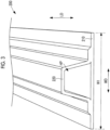
- Fig. 3 is a view illustrating an example of a composite 200 manufactured by the forming apparatus 100 illustrated in Fig. 1 .
- the forming apparatus 100 of the present embodiment is the following apparatus.
- a bagging film 30 is used for an upper die.
- Fiber base materials FB1 and FB2 to be aligned in a forming die 20 serving as a lower die are sealed in a sealed space CS, and a pressure of the sealed space CS is reduced.
- the forming apparatus 100 performs infusion molding for curing a thermosetting resin material RM by filling the sealed space CS with the thermosetting resin material RM.
- the forming apparatus 100 of the present embodiment forms a composite (fiber-reinforced composite) 200 illustrated in Fig. 3 .
- the composite 200 illustrated in Fig. 3 is a stringer used as a reinforcing material for reinforcing a fuselage and a main wing structure of aircraft.
- the composite 200 is a member having a long shape extending along a longitudinal direction LD and having a protruding central part in a width direction WD.
- the width direction WD is a direction orthogonal to the longitudinal direction LD on a surface on which the composite 200 is installed.
- the composite 200 includes a flat part 210 having a width W1 along the width direction WD and formed in a flat shape, and a protruding part 220 connected to the flat part 210 and protruding upward in the central part in the width direction WD.
- the flat part 210 and the protruding part 220 are integrally formed by using the thermosetting resin material RM.
- the flat part 210 is obtained by infiltrating the thermosetting resin material RM into the fiber base material FB1 illustrated in Figs. 1 and 2 .
- the protruding part 220 is obtained by infiltrating the thermosetting resin material RM into the fiber base material FB2 illustrated in Figs. 1 and 2 .
- a fiber base material FB1 and a fiber base material FB2 are members in which sheets formed of a reinforcing fiber material such as a carbon fiber and a glass fiber are laminated over a plurality of layers.
- the thermosetting resin material RM is an epoxy resin, unsaturated polyester, vinyl ester, phenol, cyanate ester or polyimide.
- the composite 200 illustrated in Fig. 3 includes a hollow part HP defined by the flat part 210 and the protruding part 220 and extending along the longitudinal direction LD.
- the forming apparatus 100 of the present embodiment uses a core part 10 serving as a core inserted into the hollow part HP to constantly form the composite 200 having the hollow part HP.
- the composite 200 is formed in a state where the core part 10 is inserted into the hollow part HP. In this manner, a shape of the hollow part HP can be maintained to have a constant shape when the composite 200 is formed.
- the forming apparatus 100 of the present embodiment includes the core part 10, a forming die 20, a bagging film (sealing member) 30, a suction line (suction part) 40, a resin injection line (resin injection part) 50, a communication line 60, a heating part 70, a pressure plate 80, a resin diffusion medium 82, and a suction medium 84.
- the core part 10 includes a foam 11, a cover member 12, and a connection member 13.
- the foam 11 is a member formed in a long shape in which a length in the longitudinal direction LD is longer than a length in the width direction WD.
- the foam 11 is formed of an elastic material having elasticity (for example, silicone rubber).
- the elastic material for forming the foam 11 is an open cell material illustrated in Figs. 1 and 2 .
- the open cell material has internally formed bubbles communicating with each other, and has a function of contracting when air inside the foam flows outward.
- the foam 11 is formed of the elastic material having an open cell, elasticity of the core part 10 can be improved.
- the elastic material is formed of a highly heat-resistant material such as silicone rubber. In this manner, sufficient heat resistance is provided by the heating part 70, and the core part 10 can be provided with strength for holding the shape of the hollow part HP.
- the cover member 12 is a film-shaped or sheet-shaped member that forms an internal space IS in which the foam 11 is sealed. It is preferable to use an elastic material to follow contraction and expansion of the foam. In addition, it is preferable that the cover member 12 has heat resistance to withstand heat curing of a thermosetting resin, and for example, a material thereof includes fluorocarbon rubber or the like. In addition, since the cover member 12 comes into contact with the thermosetting resin material RM infiltrating into the fiber base materials FB1 and FB2, it is necessary to provide a surface of the cover member 12 with a mold release capability. Therefore, it is necessary to perform mold release treatment on the surface of the cover member or to wrap a mold release film.
- connection member 13 is a member that connects the internal space IS sealed by the cover member 12 to a pressure-reducing source 310 such as a vacuum pump via the communication line 60. Since the communication line 60 is connected to the connection member 13, the air existing in the internal space IS can be discharged from the internal space IS, and the pressure of the internal space IS can be reduced to a pressure lower than an atmospheric pressure.
- the fiber base material FB1 and the fiber base material FB2 in which the core part 10 is accommodated in the hollow part HP are aligned, and the die forms the fiber base material FB1 and the fiber base material FB2 into a desired shape.
- the forming die 20 illustrated in Figs. 1 and 2 is a female die including a flat surface 21 having the fiber base material FB1 aligned thereon and extending along the width direction WD, and a recessed place 22 having the fiber base material FB2 aligned thereon and having a shape recessed downward from the flat surface 21.
- the bagging film 30 is a member that forms the sealed space CS by sealing the fiber base materials FB1 and FB2 in the forming die 20.
- the bagging film 30 is formed of a resin material containing nylon as a main component.
- the bagging film 30 is joined to the flat surface 21 of the forming die 20 by the sealant tape ST to cover an entire periphery of the recessed place 22 of the forming die 20.
- the suction line 40 is a tube body in which one end is connected to a suction source 330 such as a vacuum pump and the other end is connected to the sealed space CS. Since the suction source 330 and the sealed space CS are connected to each other, the suction line 40 can discharge the air existing in the sealed space CS from the sealed space CS, and can reduce the pressure of the sealed space CS to a pressure lower than the atmospheric pressure.
- a suction source 330 such as a vacuum pump
- the resin injection line 50 is a tube body that injects the thermosetting resin material RM into the fiber base materials FB1 and FB2 sealed in the sealed space CS whose pressure is reduced by the suction line 40.
- One end of the resin injection line 50 is connected to a supply source 320 for supplying the thermosetting resin material RM, and the other end is connected to the sealed space CS. Since the supply source 320 and the sealed space CS are connected to each other, the resin injection line 50 can supply the thermosetting resin material RM from the supply source 320 to the sealed space CS whose pressure is reduced by the suction line 40.
- the communication line 60 is a tube body in which one end is connected to the pressure-reducing source 310 and the other end is connected to the connection member 13 of the core part 10.
- the communication line 60 can reduce the pressure of the internal space IS of the core part 10 by connecting the pressure-reducing source 310 and the connection member 13 to each other.
- the communication line 60 is used so that the internal space IS is maintained at the atmospheric pressure when the thermosetting resin material RM is heated by the heating part 70.
- the heating part 70 is a heat source that heats and cures the thermosetting resin material RM injected into the fiber base materials FB1 and FB2 by the resin injection line 50 in the sealed space CS whose pressure is reduced by the suction line 40. As illustrated in Figs. 1 and 2 , the heating part 70 is aligned above the bagging film 30. The heating part 70 may be aligned not only above the bagging film 30 but also below the forming die 20 or inside the forming die 20. In addition, the heating part 70 may be aligned only below the forming die 20 or only inside the forming die 20, and may perform heating by using a method for blowing hot air into a space, such as an oven.
- the pressure plate 80 is a plate-like component aligned above the fiber base material FB1 aligned in the forming die 20, and is formed of a metallic material, for example.
- the pressure plate 80 uses its own weight to apply a pressure to the fiber base material FB1. In this manner, the pressure plate 80 can smooth the surface of the flat part 210 of the composite 200 obtained by infiltrating the thermosetting resin material RM into the fiber base material FB1.
- the resin diffusion medium 82 is a sheet-shaped medium for supplying the thermosetting resin material RM supplied from the resin injection line 50 to the sealed space CS while diffusing the thermosetting resin material RM to the entire fiber base material FB1.
- the resin diffusion medium 82 has a net-shaped internal structure, and has a structure through the inside of which the thermosetting resin material RM can pass. Therefore, the thermosetting resin material RM supplied to the sealed space CS whose pressure is reduced by the suction line 40 passes through the inside of the resin diffusion medium 82, and is diffused to the entire surface of the fiber base material FB1, and infiltrates into the fiber base material FB1.
- the suction medium 84 is a sheet-shaped medium for guiding the surplus thermosetting resin material RM passing through the fiber base material FB1 and the fiber base material FB2 to the suction line 40 while diffusing the surplus thermosetting resin material RM.
- the suction medium 84 has a net-shaped internal structure, and has a structure through the inside of which the thermosetting resin material RM can pass. Therefore, the surplus thermosetting resin material RM passing through the fiber base material FB1 and the fiber base material FB2 is guided to the suction medium 84 from the surface of the fiber base material FB2, passes through the inside of the suction medium 84, and is guided to the suction line 40.
- Fig. 4 is a flowchart illustrating the composite forming method according to the present embodiment.
- Fig. 5 is a cross-sectional view illustrating the forming apparatus 100 before the fiber base materials FB1 and FB2 are aligned in the forming die 20.
- Step S101 alignment step
- the fiber base material FB1 and the fiber base material FB2 in which the core part 10 is accommodated in the hollow part HP are aligned in the recessed place 22 of the forming die 20.
- the suction medium 84 is aligned in the recessed place 22 of the forming die 20
- the fiber base material FB2 is aligned on the suction medium 84
- the core part 10 is aligned on the fiber base material FB2.
- Fig. 6 is a cross-sectional view illustrating the forming apparatus 100 after the fiber base materials FB1 and FB2 are aligned in the forming die 20.
- Step S102 the fiber base material FB1 and the fiber base material FB2 are sealed in the forming die 20 to form the sealed space CS.
- the bagging film 30 is joined to the flat surface 21 of the forming die 20 by the sealant tape ST to cover an entire periphery of the recessed place 22 of the forming die 20, thereby forming the sealed space CS.
- the sealing step in Step S102 is completed, the forming apparatus 100 is brought into a state illustrated in Fig. 1 .
- Step S102 the resin injection line 50 connected to the supply source 320 of the thermosetting resin material RM and the sealed space CS are brought into a state of communicating with each other.
- the suction line 40 connected to the suction source 330 and the sealed space CS are brought into a state of communicating with each other.
- Step S103 injection step
- the air in the sealed space CS formed by Step S102 is suctioned to reduce the pressure of the sealed space CS, and the thermosetting resin material RM is injected into the fiber base materials FB1 and FB2 sealed in the sealed space CS.
- the suction source 330 is operated, the air existing in the sealed space CS is discharged from the sealed space CS via the suction line 40, and the pressure of the sealed space CS is reduced to a vacuum state where the pressure is lower than the atmospheric pressure or a pressure close to the vacuum state.
- thermosetting resin material RM can be supplied to the resin injection line 50, and the thermosetting resin material RM is supplied to the sealed space CS by using a pressure difference between the resin injection line 50 and the sealed space CS whose pressure is reduced.
- the thermosetting resin material RM supplied to the sealed space CS passes through the inside of the resin diffusion medium 82, is diffused to the entire surface of the fiber base material FB1, and is injected into the fiber base material FB1. In this manner, the thermosetting resin material RM is brought into a state of infiltrating into the fiber base materials FB1 and FB2.
- thermosetting resin material RM infiltrating into the fiber base material FB1 further infiltrates into the fiber base material FB2.
- a portion of the thermosetting resin material RM infiltrating into the fiber base material FB2 passes through the inside of the suction medium 84, is guided to the suction line 40, and is discharged to the suction line 40 as the surplus thermosetting resin material RM.
- Step S103 injection step
- the pressure of the sealed space CS is reduced to the vacuum state or the pressure close to the vacuum state. Accordingly, the fiber base materials FB1 and FB2 and the thermosetting resin material RM infiltrating into the fiber base materials FB1 and FB2 are pressurized by the atmospheric pressure.
- the shape of the hollow part HP of the fiber base materials FB1 and FB2 it is necessary to hold the shape of the core part 10 accommodated in the hollow part HP.
- Step S103 injection step
- the pressure-reducing source 310 communicating with the internal space IS of the core part 10 via the communication line 60 is adjusted so that the pressure of the internal space IS maintains an atmospheric pressure state or the pressure close to the atmospheric pressure. In this manner, the shape of the core part 10 accommodated in the hollow part HP is held.
- Step S104 the thermosetting resin material RM injected into the fiber base material FB1 and the fiber base material FB2 in Step S103 (injection step) is heated to a temperature the same as or higher than a thermosetting temperature by the heating part 70, and the thermosetting resin material RM is cured.
- Step S104 (curing step) the internal space IS of the core part 10 is heated by the heating part 70. Therefore, when the internal space IS remains in a sealed state, the air in the internal space IS expands, thereby causing a possibility that the shape of the hollow part HP may be deformed.
- Step S104 the pressure-reducing source 310 communicating with the internal space IS of the core part 10 via the communication line 60 is adjusted.
- the communication line 60 is caused to communicate with an external space maintained to have the atmospheric pressure, and the pressure of the internal space IS maintains the atmospheric pressure state or the pressure close to the atmospheric pressure. In this manner, the shape of the core part 10 accommodated in the hollow part HP is held.
- Step S104 (curing step) an internal pressure of the sealed container may be adjusted so that the pressure of the internal space IS and the internal pressure of the sealed container maintain a predetermined pressure difference.
- the pressure plate 80 a pressure plate having a sufficient weight to such an extent that the pressure plate does not move with respect to the pressure generated by expansion of the air in the internal space IS may be adopted. In this case, even when a force of expanding the hollow part HP acts due to the expansion of the air in the internal space IS, the pressure plate 80 does not move due to the force. Accordingly, it is possible to prevent the shape of the hollow part HP from being deformed.
- the cover member 12 of the core part 10 is aligned in a state of being in contact with the fiber base material FB1.
- a slight clearance may be formed between the core part 10 and the fiber base material FB1.
- the alignment step in a state where a portion of the core part 10 is not in contact with the fiber base material FB1, the fiber base material FB1 and the fiber base material FB2 are aligned in the forming die 20. Since the core part 10 thermally expands due to the heating, the clearance is formed. In this manner, it is possible to prevent the fiber base material FB1 and the fiber base material FB2 from being excessively pushed due to filling of the clearance between the cover member 12 and the fiber base material FB1 when the heating is performed in the curing step.
- Step S105 (detachment step) the composite 200 including the thermosetting resin material RM cured in Step S104 (curing step), the fiber base material FB1, and the fiber base material FB2 is detached from the forming die 20.
- the sealant tape ST that joins the bagging film 30 and the flat part 210 of the forming die 20 is removed, and the bagging film 30 is detached from the forming die 20.
- Fig. 7 is a longitudinal sectional view illustrating the composite 200 and the core part 10 which are detached from the forming die 20.
- Step S106 the pressure of the internal space IS sealed by the cover member 12 is reduced so that the foam 11 contracts, and the core part 10 accommodated in the hollow part HP of the composite 200 is removed.
- the pressure-reducing source 310 is operated to discharge the air existing in the internal space IS from the internal space IS, and the pressure in the internal space IS is reduced to the pressure lower than the atmospheric pressure.
- Fig. 8 is a longitudinal sectional view illustrating the core part 10 and the composite 200 in which the pressure of the internal space IS is reduced.
- the foam 11 of the core part 10 contracts due to an action of the atmospheric pressure.
- a clearance CL1 is formed between the core part 10 and the flat part 210 of the composite 200
- a clearance CL2 is formed between the core part 10 and the protruding part 220 of the composite 200.
- Fig. 9 is a longitudinal sectional view illustrating the composite 200 and the core part 10 partially pulled out from the hollow part HP of the composite 200.
- the core part 10 inserted into the hollow part HP of the composite 200 includes the cover member 12 and the foam 11 aligned in the internal space IS of the cover member 12.
- the core part 10A inserted into the hollow part HP of the composite 200 may include a cover member 12A including an inner cover 12Aa and an outer cover 12Ab, and the foam 11.
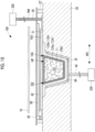
- Fig. 10 is a cross-sectional view illustrating the forming apparatus 100 according to a modification example of the embodiment.
- the inner cover (inner cover) 12Aa is a film-shaped or sheet-shaped member that forms a first internal space IS1 in which the foam 11 is sealed.
- the first internal space IS1 sealed by the inner cover 12Aa is connected to the pressure-reducing source 310 illustrated in Fig. 2 .
- the outer cover (outer cover) 12Ab is a film-shaped or sheet-shaped member that accommodates the inner cover 12Aa and forms a second internal space IS2 with the inner cover 12Aa.
- the second internal space IS2 is connected to another pressure-reducing source (not illustrated) different from the pressure-reducing source 310.
- Step S103 injection step
- Step S104 curing step
- the pressure-reducing source 310 connected to the first internal space IS1 reduces the pressure of the first internal space IS1 sealed by the inner cover 12Aa to the pressure lower than the atmospheric pressure, and adjusts the foam 11 not to expand after being heated by the heating part 70.
- a pressure-reducing source (not illustrated) connected to the second internal space IS2 is adjusted so that the second internal space IS2 sealed by the outer cover 12Ab is maintained at the atmospheric pressure.
- the pressure of the sealed space CS is reduced by the suction source 330.
- the second internal space IS2 aligned inside the sealed space CS maintains the atmospheric pressure. Therefore, it is possible to prevent the outer cover 12Ab from being deformed so that the hollow part HP contracts after coming into contact with the fiber base materials FB1 and FB2.
- Step S103 injection step
- Step S104 curing step
- the fiber base materials FB1 and FB2 in which the core part 10 is accommodated in the hollow part HP are aligned in the forming die 20.
- the fiber base materials FB1 and FB2 are sealed in the forming die 20 to form the sealed space CS.
- the pressure of the sealed space CS is reduced, the thermosetting resin material RM is injected into the fiber base materials FB1 and FB2, and the thermosetting resin material RM is heated and cured.
- the composite 200 including the cured thermosetting resin material RM and fiber base materials FB1 and FB2 is formed.
- thermosetting resin material RM When the thermosetting resin material RM is cured after being injected into the fiber base materials FB1 and FB2, the core part 10 is accommodated in the hollow part HP of the fiber base materials FB1 and FB2. Therefore, the shape of the hollow part HP of the fiber base materials FB1 and FB2 can be maintained.
- the fiber-reinforced composite forming method of the present embodiment after the composite 200 is detached from the forming die 20, the pressure of the internal space IS of the core part 10 sealed by the cover member 12 is reduced so that the foam 11 contracts. In this manner, the clearances CL1 and CL2 are formed between the core part 10 and the hollow part HP of the composite 200. Therefore, the core part 10 accommodated in the hollow part HP can be easily removed. In this way, according to the fiber-reinforced composite forming method of the present embodiment, the composite 200 including the hollow part HP can be formed without requiring complicated work.
- thermosetting resin material RM can be injected into the fiber base materials FB1 and FB2 via the resin injection line 50 by reducing the pressure of the sealed space CS via the suction line 40.
- the thermosetting resin material RM can infiltrate into the fiber base materials FB1 and FB2 by utilizing a differential pressure between the pressure of the sealed space CS and the atmospheric pressure.
- the internal space IS maintains the atmospheric pressure when the thermosetting resin material RM is heated. Therefore, it is possible to suppress a disadvantage that the hollow part HP of the fiber base materials FB1 and FB2 may be deformed when the air existing in the internal space IS is pressurized to the atmospheric pressure or higher.
- the foam 11 is formed of the elastic material having the open cell. Therefore, the foam can sufficiently contract by reducing the pressure of the internal space IS sealed by the cover member 12. 11, and the core part 10 can be easily removed from the hollow part HP of the fiber-reinforced composite.
- Fig. 11 is a longitudinal sectional view illustrating the forming apparatus 100A according to the second embodiment of the present disclosure.
- the present embodiment is a modification example of the first embodiment, and is the same as the first embodiment except for a case described below. Thus, description thereof will be omitted below.
- the core part 10 of the forming apparatus 100 of the first embodiment connects the connection member 13 and the pressure-reducing source 310 to each other via the communication line 60.
- the forming apparatus 100A of the present embodiment connects the connection member 13 and the sealed space CS to each other via a communication part 14.
- the core part 10 of the forming apparatus 100A of the present embodiment includes the communication part 14 and a membrane 15.
- the communication part 14 is a tube body in which one end is connected to the connection member 13 and the other end is open to the sealed space CS.
- the membrane 15 is attached to an end portion where the communication part 14 is open to the sealed space CS.
- the membrane 15 is a separation membrane that does not allow permeation of the thermosetting resin material RM while allowing the air to permeate between the internal space IS and the sealed space CS.
- the membrane 15 is provided to prevent the thermosetting resin material RM injected into the sealed space CS from entering the internal space IS of the core part 10.
- the forming method for using the forming apparatus 100A of the present embodiment is different from the forming method for using the forming apparatus 100 of the first embodiment in the following points.
- a first different point is that an operation in Step S103 (injection step) in Fig. 4 according to the first embodiment is different.
- the shape of the core part 10 accommodated in the hollow part HP is held by causing the pressure of the internal space IS to maintain the atmospheric pressure state or the pressure close to the atmospheric pressure.
- the internal space IS and the sealed space CS communicate with each other via the communication part 14. Therefore, in the injection step of the present embodiment, the air in the internal space IS is guided to the suction line 40 via the internal space IS by reducing the pressure of the sealed space CS via the suction line 40.
- the pressure of the internal space IS is reduced to the vacuum state or the pressure close to the vacuum state.
- the sealed space CS is reduced to the vacuum state or the pressure close to the vacuum state, the bagging film 30 and the pressure plate 80A are pressed toward the forming die 20 by the action of the atmospheric pressure.
- the pressure plate 80A of the present embodiment has a shape that comes into contact with the flat surface 21 of the forming die 20 to surround the recessed place 22. Therefore, even when the pressure plate 80A is pressed toward the forming die 20, the pressure plate 80A comes into contact with the forming die 20 so that a position of the pressure plate 80A is maintained. Therefore, the shapes of the fiber base materials FB1 and FB2 aligned below the pressure plate 80A are maintained.
- the shape of the core part 10 is maintained. In this manner, the shapes of the fiber base materials FB1 and FB2 are maintained in the injection step.
- Step S104 curing step in Fig. 4 according to the first embodiment is different.
- the pressure of the internal space IS of the core part 10 maintains the atmospheric pressure state or the pressure close to the atmospheric pressure so that the shape of the core part 10 accommodated in the hollow part HP is held.
- the pressure of the internal space IS of the core part 10 maintains the same pressure as the pressure of the sealed space CS. That is, the internal space IS and the sealed space CS communicate with each other by the communication part 14. Therefore, the pressure of the internal space IS of the core part 10 and the pressure of the sealed space CS are maintained to be the same as each other.
- the air in the internal space IS expands by the heating part 70.
- the pressure of the internal space IS is reduced to the vacuum state or a state close to the vacuum state where the pressure of the internal space IS is the same as the pressure of the sealed space CS, all or most of the air in the internal space IS are discharged outward. Therefore, even when the air in the internal space IS expands by the heating part 70, the shape of the core part 10 is hardly changed. Therefore, the shape of the core part 10 accommodated in the hollow part HP can be held.
- the core part 10 includes the communication part 14. Therefore, the pressure of the sealed space CS is reduced via the suction line 40 in the injection step. In this manner, the air in the internal space IS is guided to the suction line 40 via the sealed space CS. In the curing step, the internal space IS is heated in a state where the air is reduced. Therefore, even when the internal space expands due to the heating, there is no possibility that the core part may be excessively deformed to deform the hollow part of the fiber base material.
- the resin injection line 50 is provided above the forming die 20, and the suction line 40 is provided in the recessed place 22 of the forming die 20.
- the resin injection line 50 may be provided in the recessed place 22 of the forming die 20, and the suction line 40 may be provided above the forming die 20.
- the forming die 20 is the female die having the flat surface 21 and the recessed place 22 having a shape recessed downward from the flat surface 21.
- the forming die 20 may be a male die having a flat surface and a protruding part protruding upward from the flat surface.
- the fiber-reinforced composite forming method in the above-described embodiment can be understood as follows, for example.
- the fiber-reinforced composite forming method including the alignment step (S101) of aligning the fiber base material (FB1, FB2) in which the core part (10) including the elastic long foam (11) and the cover member (12) for sealing the foam is accommodated in the hollow part (HP), in the forming die (20), the sealing step (S102) of sealing the fiber base material in the forming die to form the sealed space (CS), the injection step (S103) of suctioning the air in the sealed space formed by the sealing step, reducing the pressure in the sealed space, and injecting the thermosetting resin material into the fiber base material sealed in the sealed space, the curing step (S104) of heating and curing the thermosetting resin material injected into the fiber base material by the injection step, the detachment step (S105) of detaching the fiber-reinforced composite (200) including the thermosetting resin material cured by the curing step and the fiber base material, from the forming die, and the removal step (S106) of reducing the pressure of the internal
- the fiber base material in which the core part is accommodated in the hollow part is aligned in the forming die.
- the fiber base material is sealed in the forming die to form the sealed space.
- the pressure of the sealed space is reduced, the thermosetting resin material is injected into the fiber base material, and the thermosetting resin material RM is heated and cured.
- the fiber-reinforced composite including the cured thermosetting resin material and the fiber base material is formed.
- the thermosetting resin is cured after being injected into the fiber base material, the core part is accommodated in the hollow part of the fiber base material. Therefore, the shape of the hollow part of the fiber base material can be maintained.
- the fiber-reinforced composite forming method in the present disclosure after the fiber-reinforced composite is detached from the forming die, the pressure of the internal space of the core part sealed by the cover member is reduced so that the foam contracts. In this manner, the clearance is formed between the core part and the hollow part of the fiber-reinforced composite. Therefore, the core part accommodated in the hollow part can be easily removed. In this way, according to the fiber-reinforced composite forming method in the present disclosure, the fiber-reinforced composite including the hollow part can be formed without requiring complicated work.
- the resin injection line (50) connected to the supply source (320) of the thermosetting resin material and the sealed space are caused to communicate with each other, and the suction line (40) connected to the suction source (330) and the sealed space are caused to communicate with each other.
- the thermosetting resin material is injected into the fiber base material via the resin injection line by reducing the pressure of the sealed space via the suction line.
- the thermosetting resin material can be injected into the fiber base material via the resin injection line by reducing the pressure of the sealed space via the suction line.
- the thermosetting resin material can infiltrate into the fiber base material by utilizing the differential pressure between the pressure of the sealed space and the atmospheric pressure.
- the fiber-reinforced composite forming method having the above-described configuration, it is preferable to adopt the following configuration.
- the internal space is maintained at the atmospheric pressure when the thermosetting resin material is heated.
- the internal space maintains the atmospheric pressure when the thermosetting resin material is heated. Therefore, it is possible to suppress a disadvantage that the hollow part of the fiber base material may be deformed when the air existing in the internal space is pressurized to the atmospheric pressure or higher.
- the core part includes the communication part (14) through which the internal space and the sealed space communicate with each other.
- the air in the internal space is guided to the suction line via the sealed space by reducing the pressure of the sealed space via the suction line.
- the core part includes the communication part. Therefore, in the injection step, the air in the internal space is guided to the suction line via the sealed space by reducing the pressure of the sealed space via the suction line. In the curing step, the heating is performed in a state where the air in the internal space is reduced. Therefore, even when the internal space expands due to the heating, there is no possibility that the core part may be excessively deformed to deform the hollow part of the fiber base material.
- the cover member includes the inner cover for sealing the foam and the outer cover for accommodating the inner cover.
- the pressure of the first internal space sealed by the inner cover is reduced to the pressure lower than the atmospheric pressure, and the pressure of the second internal space between the inner cover and the outer cover is maintained at the atmospheric pressure.
- the pressure of the first internal space sealed by the inner cover is reduced to the pressure lower than the atmospheric pressure.
- the foam can be adjusted not to expand after being heated by the heating part.
- the pressure of the second internal space between the outer cover and the inner cover is maintained at the atmospheric pressure, it is possible to prevent the hollow part of the core part from being deformed to contract.
- the fiber base material is aligned in the forming die in a state where a portion of the core part is not in contact with the fiber base material.
- a portion of the core part does not come into contact with the fiber base material in a state before the heating starts to be performed by the heating step. Therefore, when the heating starts to be performed by the heating step and the foam expands, it is possible to prevent the fiber base material from being excessively pushed due to filling of the clearance between the portion of the core part and the fiber base material.
- the foam is formed of the elastic material having the open cell.
- the foam is formed of the elastic material having the open cell. Therefore, the foam can sufficiently contract by reducing the pressure of the internal space sealed by the cover member, and the core part can be easily removed from the hollow part of the fiber-reinforced composite.
- the fiber-reinforced composite forming apparatus in the above-described embodiment can be understood as follows, for example.
- the fiber-reinforced composite forming apparatus including the core part (10) including the elastic long foam (11) and the cover member (12) for sealing the foam, the forming die (20) in which the fiber base material (FB1, FB2) accommodating the core part in the hollow part (HP) is aligned, the sealing member (30) that seals the fiber base material in the forming die to form the sealed space (CS), the suction part (40) that suctions the air in the sealed space to reduce the pressure of the sealed space, the resin injection part (50) that injects the thermosetting resin material into the fiber base material sealed in the sealed space whose pressure is reduced by the suction part, and the heating part (60) that heats and cures the thermosetting resin material injected into the fiber base material by the resin injection part in the sealed space whose pressure is reduced by the suction part.
- the core part includes the connection member (13) that connects the internal space (IS) sealed by the cover member to the pressure-reducing source (310).
- the fiber base material in which the core part is accommodated in the hollow part is aligned in the forming die.
- the fiber base material is sealed in the forming die to form the sealed space.
- the pressure of the sealed space is reduced, the thermosetting resin material is injected into the fiber base material, and the thermosetting resin material is heated and cured.
- the fiber-reinforced composite including the cured thermosetting resin material and the fiber base material is formed.
- the thermosetting resin is cured after being injected into the fiber base material, the core part is accommodated in the hollow part of the fiber base material. Therefore, the shape of the hollow part of the fiber base material can be maintained.
- the core part includes the connection member that connects the internal space to the pressure-reducing source. Therefore, after the fiber-reinforced composite is detached from the forming die, the pressure of the internal space of the core part sealed by the cover member is reduced so that the foam contracts. In this manner, the clearance is formed between the core part and the hollow part of the fiber-reinforced composite. In this manner, the core part accommodated in the hollow part of the fiber-reinforced composite can be easily removed. In this way, according to the fiber-reinforced composite forming apparatus in the present disclosure, the fiber-reinforced composite including hollow part can be formed without requiring complicated work.
- the resin injection part is a tube body connected to the supply source (320) of the thermosetting resin material and communicating with the sealed space.
- the suction part is a tube body connected to the suction source (330) and communicating with the sealed space.
- the pressure of the sealed space is reduced via the tube body connected to the suction source.
- the thermosetting resin material can be injected into the fiber base material via the tube body connected to the supply source.
- the thermosetting resin can infiltrate into the fiber base material by utilizing the differential pressure between the pressure of the sealed space and the atmospheric pressure.
- the fiber-reinforced composite forming apparatus includes the communication line (60) that communicates with the internal space, and is maintained at the internal space at the atmospheric pressure when the thermosetting resin material is heated by the heating part.
- the fiber-reinforced composite forming apparatus includes the communication line. Therefore, the pressure of the internal space maintains the atmospheric pressure when the thermosetting resin material is heated. In this manner, it is possible to suppress a disadvantage that the hollow part of the fiber base material may be deformed when the air existing in the internal space is pressurized to the atmospheric pressure or higher.
- the core part includes the communication part (14) through which the internal space and the sealed space communicate with each other.
- the core part includes the communication part. Therefore, when the thermosetting resin material is injected by the resin injection part, the pressure of the sealed space is reduced via the suction line. In this manner, the air in the internal space is guided to the suction line via the sealed space.
- the thermosetting resin material is heated by the heating part, the foam is heated in a state where the air in the internal space is reduced. Therefore, even when the foam expands due to the heating, there is no possibility that the core part may be excessively deformed to deform the hollow part of the fiber base material.
- the cover member includes the inner cover for sealing the foam and the outer cover for accommodating the inner cover.
- the pressure of the first internal space sealed by the inner cover is reduced to the pressure lower than the atmospheric pressure, and the pressure of the second internal space between the inner cover and the outer cover maintains the atmospheric pressure.
- the pressure of the first internal space sealed by the inner cover is reduced to the pressure lower than the atmospheric pressure.
- the foam can be adjusted not to expand after being heated by the heating part.
- the pressure of the second internal space between the outer cover and the inner cover is maintained at the atmospheric pressure, it is possible to prevent the hollow part of the core part from being deformed to contract.
- the core part In a state where the thermosetting resin material is not heated by the heating part, the core part is accommodated in the hollow part in a state where a portion of the core part is not in contact with the fiber base material.
- thermosetting resin material starts to be heated by the heating part and the foam expands, it is possible to prevent the fiber base material from being excessively pushed due to filling of the clearance between the portion of the core part and the fiber base material.
- the foam is formed of the elastic material having the open cell.
- the foam is formed of the elastic material having the open cell. Therefore, the foam can sufficiently contract by reducing the pressure of the internal space sealed by the cover member, and the core part can be easily removed from the hollow part of the fiber-reinforced composite.
Landscapes
- Engineering & Computer Science (AREA)
- Mechanical Engineering (AREA)
- Chemical & Material Sciences (AREA)
- Composite Materials (AREA)
- Physics & Mathematics (AREA)
- Fluid Mechanics (AREA)
- Architecture (AREA)
- Civil Engineering (AREA)
- Structural Engineering (AREA)
- Casting Or Compression Moulding Of Plastics Or The Like (AREA)
- Moulding By Coating Moulds (AREA)
Applications Claiming Priority (1)
| Application Number | Priority Date | Filing Date | Title |
|---|---|---|---|
| PCT/JP2020/012718 WO2021191967A1 (ja) | 2020-03-23 | 2020-03-23 | 繊維強化複合材成形方法および繊維強化複合材成形装置 |
Publications (3)
| Publication Number | Publication Date |
|---|---|
| EP4059688A1 EP4059688A1 (en) | 2022-09-21 |
| EP4059688A4 EP4059688A4 (en) | 2022-12-14 |
| EP4059688B1 true EP4059688B1 (en) | 2025-01-22 |
Family
ID=77890020
Family Applications (1)
| Application Number | Title | Priority Date | Filing Date |
|---|---|---|---|
| EP20927548.6A Active EP4059688B1 (en) | 2020-03-23 | 2020-03-23 | Fiber-reinforced composite forming method and fiber-reinforced composite forming apparatus |
Country Status (3)
| Country | Link |
|---|---|
| EP (1) | EP4059688B1 (https=) |
| JP (1) | JP7318112B2 (https=) |
| WO (1) | WO2021191967A1 (https=) |
Families Citing this family (2)
| Publication number | Priority date | Publication date | Assignee | Title |
|---|---|---|---|---|
| US12611823B2 (en) * | 2022-12-13 | 2026-04-28 | The Boeing Company | In-tool compaction for composite structures |
| CN116653181B (zh) * | 2023-05-26 | 2025-05-06 | 广联航空工业股份有限公司 | 一种复合材料制造用脱模装置及其使用方法 |
Family Cites Families (11)
| Publication number | Priority date | Publication date | Assignee | Title |
|---|---|---|---|---|
| US3764641A (en) * | 1971-01-08 | 1973-10-09 | A Ash | Method of forming irregularly shaped hollow articles using a variable stiffness mandrel |
| SE509503C2 (sv) * | 1997-05-12 | 1999-02-01 | Volvo Ab | Arrangemang, förfarande och hålkropp vid formning av plastdetaljer |
| CA2347717A1 (en) * | 1998-09-30 | 2000-04-06 | Toray Industries, Inc. | A fibre-reinforced resin structure having hollow cross section and manufacturing method thereof |
| US6889937B2 (en) * | 1999-11-18 | 2005-05-10 | Rocky Mountain Composites, Inc. | Single piece co-cure composite wing |
| US9296187B2 (en) * | 2008-12-10 | 2016-03-29 | The Boeing Company | Bagging process and mandrel for fabrication of elongated composite structure |
| DE102009026456A1 (de) * | 2009-05-25 | 2010-12-16 | Airbus Operations Gmbh | Vorrichtung und Verfahren zur Herstellung eines Verbundbauteils |
| JP6209095B2 (ja) * | 2014-01-31 | 2017-10-04 | 三菱重工業株式会社 | Frp成形治具及びfrp構造体の成形方法 |
| GB2525243A (en) * | 2014-04-17 | 2015-10-21 | Airbus Operations Ltd | A method of moulding and a core plug for use in the method |
| US10086534B2 (en) * | 2014-10-17 | 2018-10-02 | The Boeing Company | Multifunctional mandrel end cap and method |
| US10926435B2 (en) * | 2017-05-03 | 2021-02-23 | The Boeing Company | Foam mandrel assembly |
| JP6715226B2 (ja) * | 2017-10-25 | 2020-07-01 | 株式会社Subaru | 複合材成形治具及び複合材成形方法 |
-
2020
- 2020-03-23 EP EP20927548.6A patent/EP4059688B1/en active Active
- 2020-03-23 JP JP2022509780A patent/JP7318112B2/ja active Active
- 2020-03-23 WO PCT/JP2020/012718 patent/WO2021191967A1/ja not_active Ceased
Also Published As
| Publication number | Publication date |
|---|---|
| JP7318112B2 (ja) | 2023-07-31 |
| JPWO2021191967A1 (https=) | 2021-09-30 |
| EP4059688A4 (en) | 2022-12-14 |
| EP4059688A1 (en) | 2022-09-21 |
| WO2021191967A1 (ja) | 2021-09-30 |
Similar Documents
| Publication | Publication Date | Title |
|---|---|---|
| US12343948B2 (en) | Diaphragm forming | |
| EP3006180B1 (en) | Method and device for manufacturing fiber-reinforced plastic | |
| RU2635623C2 (ru) | Способ формирования формованной заготовки | |
| US11701797B2 (en) | Composite material molding jig and composite material molding method | |
| CA2987004C (en) | Device and method for manufacturing fiber-reinforced plastic molded article | |
| CA2662476C (en) | Forming-molding tool and process for producing preforms and fiber reinforced plastics with the tool | |
| EP2116358B1 (en) | Method and apparatus for conforming a blank | |
| EP4059688B1 (en) | Fiber-reinforced composite forming method and fiber-reinforced composite forming apparatus | |
| CN105705320A (zh) | 用于生产复合材料部件的设备及方法 | |
| US20230294371A1 (en) | Composite material molding method | |
| US12319019B2 (en) | Fiber-reinforced composite material molding apparatus and fiber-reinforced composite material molding method | |
| JP7279102B2 (ja) | 繊維強化複合材成形方法および繊維強化複合材成形装置 | |
| EP4472832B1 (en) | Concavity diaphragm forming | |
| EP4169701B1 (en) | Fiber-reinforced composite material shaping device and fiber-reinforced composite material shaping method | |
| EP4563334A1 (en) | Molding method and molding device for composite material | |
| JP2004181658A (ja) | 繊維強化樹脂製管分岐部の製造法並びに製造装置 | |
| JP5558323B2 (ja) | 繊維強化プラスチック、その製造方法 | |
| CN115052736A (zh) | 原材料成型装置及原材料成型方法 |
Legal Events
| Date | Code | Title | Description |
|---|---|---|---|
| STAA | Information on the status of an ep patent application or granted ep patent |
Free format text: STATUS: THE INTERNATIONAL PUBLICATION HAS BEEN MADE |
|
| PUAI | Public reference made under article 153(3) epc to a published international application that has entered the european phase |
Free format text: ORIGINAL CODE: 0009012 |
|
| STAA | Information on the status of an ep patent application or granted ep patent |
Free format text: STATUS: REQUEST FOR EXAMINATION WAS MADE |
|
| 17P | Request for examination filed |
Effective date: 20220615 |
|
| AK | Designated contracting states |
Kind code of ref document: A1 Designated state(s): AL AT BE BG CH CY CZ DE DK EE ES FI FR GB GR HR HU IE IS IT LI LT LU LV MC MK MT NL NO PL PT RO RS SE SI SK SM TR |
|
| A4 | Supplementary search report drawn up and despatched |
Effective date: 20221114 |
|
| RIC1 | Information provided on ipc code assigned before grant |
Ipc: B29C 33/46 20060101ALI20221108BHEP Ipc: B29C 70/54 20060101ALI20221108BHEP Ipc: B29C 70/48 20060101ALI20221108BHEP Ipc: B29C 70/44 20060101ALI20221108BHEP Ipc: B29C 39/42 20060101AFI20221108BHEP |
|
| DAV | Request for validation of the european patent (deleted) | ||
| DAX | Request for extension of the european patent (deleted) | ||
| GRAP | Despatch of communication of intention to grant a patent |
Free format text: ORIGINAL CODE: EPIDOSNIGR1 |
|
| STAA | Information on the status of an ep patent application or granted ep patent |
Free format text: STATUS: GRANT OF PATENT IS INTENDED |
|
| INTG | Intention to grant announced |
Effective date: 20240918 |
|
| GRAS | Grant fee paid |
Free format text: ORIGINAL CODE: EPIDOSNIGR3 |
|
| GRAA | (expected) grant |
Free format text: ORIGINAL CODE: 0009210 |
|
| STAA | Information on the status of an ep patent application or granted ep patent |
Free format text: STATUS: THE PATENT HAS BEEN GRANTED |
|
| AK | Designated contracting states |
Kind code of ref document: B1 Designated state(s): AL AT BE BG CH CY CZ DE DK EE ES FI FR GB GR HR HU IE IS IT LI LT LU LV MC MK MT NL NO PL PT RO RS SE SI SK SM TR |
|
| REG | Reference to a national code |
Ref country code: GB Ref legal event code: FG4D |
|
| REG | Reference to a national code |
Ref country code: CH Ref legal event code: EP |
|
| REG | Reference to a national code |
Ref country code: IE Ref legal event code: FG4D |
|
| REG | Reference to a national code |
Ref country code: DE Ref legal event code: R096 Ref document number: 602020045381 Country of ref document: DE |
|
| REG | Reference to a national code |
Ref country code: NL Ref legal event code: MP Effective date: 20250122 |
|
| PG25 | Lapsed in a contracting state [announced via postgrant information from national office to epo] |
Ref country code: NL Free format text: LAPSE BECAUSE OF FAILURE TO SUBMIT A TRANSLATION OF THE DESCRIPTION OR TO PAY THE FEE WITHIN THE PRESCRIBED TIME-LIMIT Effective date: 20250122 |
|
| PG25 | Lapsed in a contracting state [announced via postgrant information from national office to epo] |
Ref country code: RS Free format text: LAPSE BECAUSE OF FAILURE TO SUBMIT A TRANSLATION OF THE DESCRIPTION OR TO PAY THE FEE WITHIN THE PRESCRIBED TIME-LIMIT Effective date: 20250422 |
|
| PG25 | Lapsed in a contracting state [announced via postgrant information from national office to epo] |
Ref country code: FI Free format text: LAPSE BECAUSE OF FAILURE TO SUBMIT A TRANSLATION OF THE DESCRIPTION OR TO PAY THE FEE WITHIN THE PRESCRIBED TIME-LIMIT Effective date: 20250122 |
|
| PG25 | Lapsed in a contracting state [announced via postgrant information from national office to epo] |
Ref country code: PL Free format text: LAPSE BECAUSE OF FAILURE TO SUBMIT A TRANSLATION OF THE DESCRIPTION OR TO PAY THE FEE WITHIN THE PRESCRIBED TIME-LIMIT Effective date: 20250122 |
|
| PG25 | Lapsed in a contracting state [announced via postgrant information from national office to epo] |
Ref country code: ES Free format text: LAPSE BECAUSE OF FAILURE TO SUBMIT A TRANSLATION OF THE DESCRIPTION OR TO PAY THE FEE WITHIN THE PRESCRIBED TIME-LIMIT Effective date: 20250122 |
|
| REG | Reference to a national code |
Ref country code: LT Ref legal event code: MG9D |
|
| PG25 | Lapsed in a contracting state [announced via postgrant information from national office to epo] |
Ref country code: IS Free format text: LAPSE BECAUSE OF FAILURE TO SUBMIT A TRANSLATION OF THE DESCRIPTION OR TO PAY THE FEE WITHIN THE PRESCRIBED TIME-LIMIT Effective date: 20250522 Ref country code: NO Free format text: LAPSE BECAUSE OF FAILURE TO SUBMIT A TRANSLATION OF THE DESCRIPTION OR TO PAY THE FEE WITHIN THE PRESCRIBED TIME-LIMIT Effective date: 20250422 |
|
| REG | Reference to a national code |
Ref country code: AT Ref legal event code: MK05 Ref document number: 1761157 Country of ref document: AT Kind code of ref document: T Effective date: 20250122 |
|
| PG25 | Lapsed in a contracting state [announced via postgrant information from national office to epo] |
Ref country code: HR Free format text: LAPSE BECAUSE OF FAILURE TO SUBMIT A TRANSLATION OF THE DESCRIPTION OR TO PAY THE FEE WITHIN THE PRESCRIBED TIME-LIMIT Effective date: 20250122 |
|
| PG25 | Lapsed in a contracting state [announced via postgrant information from national office to epo] |
Ref country code: LV Free format text: LAPSE BECAUSE OF FAILURE TO SUBMIT A TRANSLATION OF THE DESCRIPTION OR TO PAY THE FEE WITHIN THE PRESCRIBED TIME-LIMIT Effective date: 20250122 Ref country code: PT Free format text: LAPSE BECAUSE OF FAILURE TO SUBMIT A TRANSLATION OF THE DESCRIPTION OR TO PAY THE FEE WITHIN THE PRESCRIBED TIME-LIMIT Effective date: 20250522 |
|
| PG25 | Lapsed in a contracting state [announced via postgrant information from national office to epo] |
Ref country code: BG Free format text: LAPSE BECAUSE OF FAILURE TO SUBMIT A TRANSLATION OF THE DESCRIPTION OR TO PAY THE FEE WITHIN THE PRESCRIBED TIME-LIMIT Effective date: 20250122 Ref country code: GR Free format text: LAPSE BECAUSE OF FAILURE TO SUBMIT A TRANSLATION OF THE DESCRIPTION OR TO PAY THE FEE WITHIN THE PRESCRIBED TIME-LIMIT Effective date: 20250423 |
|
| PG25 | Lapsed in a contracting state [announced via postgrant information from national office to epo] |
Ref country code: AT Free format text: LAPSE BECAUSE OF FAILURE TO SUBMIT A TRANSLATION OF THE DESCRIPTION OR TO PAY THE FEE WITHIN THE PRESCRIBED TIME-LIMIT Effective date: 20250122 |
|
| PG25 | Lapsed in a contracting state [announced via postgrant information from national office to epo] |
Ref country code: SE Free format text: LAPSE BECAUSE OF FAILURE TO SUBMIT A TRANSLATION OF THE DESCRIPTION OR TO PAY THE FEE WITHIN THE PRESCRIBED TIME-LIMIT Effective date: 20250122 |
|
| PG25 | Lapsed in a contracting state [announced via postgrant information from national office to epo] |
Ref country code: SM Free format text: LAPSE BECAUSE OF FAILURE TO SUBMIT A TRANSLATION OF THE DESCRIPTION OR TO PAY THE FEE WITHIN THE PRESCRIBED TIME-LIMIT Effective date: 20250122 |
|
| PG25 | Lapsed in a contracting state [announced via postgrant information from national office to epo] |
Ref country code: DK Free format text: LAPSE BECAUSE OF FAILURE TO SUBMIT A TRANSLATION OF THE DESCRIPTION OR TO PAY THE FEE WITHIN THE PRESCRIBED TIME-LIMIT Effective date: 20250122 |
|
| PG25 | Lapsed in a contracting state [announced via postgrant information from national office to epo] |
Ref country code: MC Free format text: LAPSE BECAUSE OF FAILURE TO SUBMIT A TRANSLATION OF THE DESCRIPTION OR TO PAY THE FEE WITHIN THE PRESCRIBED TIME-LIMIT Effective date: 20250122 |
|
| PG25 | Lapsed in a contracting state [announced via postgrant information from national office to epo] |
Ref country code: IT Free format text: LAPSE BECAUSE OF FAILURE TO SUBMIT A TRANSLATION OF THE DESCRIPTION OR TO PAY THE FEE WITHIN THE PRESCRIBED TIME-LIMIT Effective date: 20250122 |
|
| PG25 | Lapsed in a contracting state [announced via postgrant information from national office to epo] |
Ref country code: CZ Free format text: LAPSE BECAUSE OF FAILURE TO SUBMIT A TRANSLATION OF THE DESCRIPTION OR TO PAY THE FEE WITHIN THE PRESCRIBED TIME-LIMIT Effective date: 20250122 Ref country code: EE Free format text: LAPSE BECAUSE OF FAILURE TO SUBMIT A TRANSLATION OF THE DESCRIPTION OR TO PAY THE FEE WITHIN THE PRESCRIBED TIME-LIMIT Effective date: 20250122 |
|
| REG | Reference to a national code |
Ref country code: CH Ref legal event code: H13 Free format text: ST27 STATUS EVENT CODE: U-0-0-H10-H13 (AS PROVIDED BY THE NATIONAL OFFICE) Effective date: 20251023 Ref country code: DE Ref legal event code: R097 Ref document number: 602020045381 Country of ref document: DE |
|
| PG25 | Lapsed in a contracting state [announced via postgrant information from national office to epo] |
Ref country code: RO Free format text: LAPSE BECAUSE OF FAILURE TO SUBMIT A TRANSLATION OF THE DESCRIPTION OR TO PAY THE FEE WITHIN THE PRESCRIBED TIME-LIMIT Effective date: 20250122 |
|
| PG25 | Lapsed in a contracting state [announced via postgrant information from national office to epo] |
Ref country code: SK Free format text: LAPSE BECAUSE OF FAILURE TO SUBMIT A TRANSLATION OF THE DESCRIPTION OR TO PAY THE FEE WITHIN THE PRESCRIBED TIME-LIMIT Effective date: 20250122 |
|
| PG25 | Lapsed in a contracting state [announced via postgrant information from national office to epo] |
Ref country code: LU Free format text: LAPSE BECAUSE OF NON-PAYMENT OF DUE FEES Effective date: 20250323 |
|
| PLBE | No opposition filed within time limit |
Free format text: ORIGINAL CODE: 0009261 |
|
| STAA | Information on the status of an ep patent application or granted ep patent |
Free format text: STATUS: NO OPPOSITION FILED WITHIN TIME LIMIT |
|
| REG | Reference to a national code |
Ref country code: BE Ref legal event code: MM Effective date: 20250331 |
|
| GBPC | Gb: european patent ceased through non-payment of renewal fee |
Effective date: 20250422 |
|
| 26N | No opposition filed |
Effective date: 20251023 |
|
| PG25 | Lapsed in a contracting state [announced via postgrant information from national office to epo] |
Ref country code: GB Free format text: LAPSE BECAUSE OF NON-PAYMENT OF DUE FEES Effective date: 20250422 |
|
| PG25 | Lapsed in a contracting state [announced via postgrant information from national office to epo] |
Ref country code: BE Free format text: LAPSE BECAUSE OF NON-PAYMENT OF DUE FEES Effective date: 20250331 |
|
| PG25 | Lapsed in a contracting state [announced via postgrant information from national office to epo] |
Ref country code: CH Free format text: LAPSE BECAUSE OF NON-PAYMENT OF DUE FEES Effective date: 20250331 |
|
| PG25 | Lapsed in a contracting state [announced via postgrant information from national office to epo] |
Ref country code: IE Free format text: LAPSE BECAUSE OF NON-PAYMENT OF DUE FEES Effective date: 20250323 |
|
| PGFP | Annual fee paid to national office [announced via postgrant information from national office to epo] |
Ref country code: DE Payment date: 20260128 Year of fee payment: 7 |
|
| PGFP | Annual fee paid to national office [announced via postgrant information from national office to epo] |
Ref country code: FR Payment date: 20260209 Year of fee payment: 7 |