EP4056847B1 - Hydraulikpumpensystem - Google Patents
Hydraulikpumpensystem Download PDFInfo
- Publication number
- EP4056847B1 EP4056847B1 EP22275025.9A EP22275025A EP4056847B1 EP 4056847 B1 EP4056847 B1 EP 4056847B1 EP 22275025 A EP22275025 A EP 22275025A EP 4056847 B1 EP4056847 B1 EP 4056847B1
- Authority
- EP
- European Patent Office
- Prior art keywords
- pump
- hydraulic
- housing
- working vehicle
- optionally
- Prior art date
- Legal status (The legal status is an assumption and is not a legal conclusion. Google has not performed a legal analysis and makes no representation as to the accuracy of the status listed.)
- Active
Links
- 239000012530 fluid Substances 0.000 claims description 132
- 239000000446 fuel Substances 0.000 claims description 23
- 238000006073 displacement reaction Methods 0.000 claims description 13
- 239000011358 absorbing material Substances 0.000 claims description 11
- 238000007789 sealing Methods 0.000 claims description 11
- 239000000463 material Substances 0.000 description 17
- 238000012423 maintenance Methods 0.000 description 9
- 229910000831 Steel Inorganic materials 0.000 description 8
- 239000004411 aluminium Substances 0.000 description 8
- 229910052782 aluminium Inorganic materials 0.000 description 8
- XAGFODPZIPBFFR-UHFFFAOYSA-N aluminium Chemical compound [Al] XAGFODPZIPBFFR-UHFFFAOYSA-N 0.000 description 8
- 239000007769 metal material Substances 0.000 description 8
- 239000004033 plastic Substances 0.000 description 8
- 229920003023 plastic Polymers 0.000 description 8
- 239000010959 steel Substances 0.000 description 8
- 230000005540 biological transmission Effects 0.000 description 7
- 238000002485 combustion reaction Methods 0.000 description 6
- 230000009286 beneficial effect Effects 0.000 description 5
- 125000006850 spacer group Chemical group 0.000 description 4
- 238000003466 welding Methods 0.000 description 4
- 238000006243 chemical reaction Methods 0.000 description 3
- 238000001816 cooling Methods 0.000 description 3
- 230000005611 electricity Effects 0.000 description 3
- 238000009499 grossing Methods 0.000 description 3
- 230000001133 acceleration Effects 0.000 description 2
- 239000000853 adhesive Substances 0.000 description 2
- 230000001070 adhesive effect Effects 0.000 description 2
- 230000008878 coupling Effects 0.000 description 2
- 238000010168 coupling process Methods 0.000 description 2
- 238000005859 coupling reaction Methods 0.000 description 2
- 230000003628 erosive effect Effects 0.000 description 2
- 238000001914 filtration Methods 0.000 description 2
- 239000002184 metal Substances 0.000 description 2
- 229910052751 metal Inorganic materials 0.000 description 2
- 238000005086 pumping Methods 0.000 description 2
- 230000008439 repair process Effects 0.000 description 2
- XLYOFNOQVPJJNP-UHFFFAOYSA-N water Substances O XLYOFNOQVPJJNP-UHFFFAOYSA-N 0.000 description 2
- UFHFLCQGNIYNRP-UHFFFAOYSA-N Hydrogen Chemical compound [H][H] UFHFLCQGNIYNRP-UHFFFAOYSA-N 0.000 description 1
- 238000005452 bending Methods 0.000 description 1
- 230000015572 biosynthetic process Effects 0.000 description 1
- 238000004140 cleaning Methods 0.000 description 1
- 230000000295 complement effect Effects 0.000 description 1
- 238000010276 construction Methods 0.000 description 1
- 239000012809 cooling fluid Substances 0.000 description 1
- 229910052739 hydrogen Inorganic materials 0.000 description 1
- 239000001257 hydrogen Substances 0.000 description 1
- 230000004941 influx Effects 0.000 description 1
- 238000004519 manufacturing process Methods 0.000 description 1
- 238000000034 method Methods 0.000 description 1
- 238000012986 modification Methods 0.000 description 1
- 230000004048 modification Effects 0.000 description 1
- 230000003068 static effect Effects 0.000 description 1
Images


Classifications
-
- E—FIXED CONSTRUCTIONS
- E02—HYDRAULIC ENGINEERING; FOUNDATIONS; SOIL SHIFTING
- E02F—DREDGING; SOIL-SHIFTING
- E02F9/00—Component parts of dredgers or soil-shifting machines, not restricted to one of the kinds covered by groups E02F3/00 - E02F7/00
- E02F9/20—Drives; Control devices
- E02F9/22—Hydraulic or pneumatic drives
- E02F9/2221—Control of flow rate; Load sensing arrangements
- E02F9/2232—Control of flow rate; Load sensing arrangements using one or more variable displacement pumps
-
- F—MECHANICAL ENGINEERING; LIGHTING; HEATING; WEAPONS; BLASTING
- F04—POSITIVE - DISPLACEMENT MACHINES FOR LIQUIDS; PUMPS FOR LIQUIDS OR ELASTIC FLUIDS
- F04B—POSITIVE-DISPLACEMENT MACHINES FOR LIQUIDS; PUMPS
- F04B23/00—Pumping installations or systems
- F04B23/02—Pumping installations or systems having reservoirs
- F04B23/021—Pumping installations or systems having reservoirs the pump being immersed in the reservoir
-
- F—MECHANICAL ENGINEERING; LIGHTING; HEATING; WEAPONS; BLASTING
- F15—FLUID-PRESSURE ACTUATORS; HYDRAULICS OR PNEUMATICS IN GENERAL
- F15B—SYSTEMS ACTING BY MEANS OF FLUIDS IN GENERAL; FLUID-PRESSURE ACTUATORS, e.g. SERVOMOTORS; DETAILS OF FLUID-PRESSURE SYSTEMS, NOT OTHERWISE PROVIDED FOR
- F15B1/00—Installations or systems with accumulators; Supply reservoir or sump assemblies
- F15B1/26—Supply reservoir or sump assemblies
- F15B1/265—Supply reservoir or sump assemblies with pressurised main reservoir
-
- E—FIXED CONSTRUCTIONS
- E02—HYDRAULIC ENGINEERING; FOUNDATIONS; SOIL SHIFTING
- E02F—DREDGING; SOIL-SHIFTING
- E02F9/00—Component parts of dredgers or soil-shifting machines, not restricted to one of the kinds covered by groups E02F3/00 - E02F7/00
- E02F9/20—Drives; Control devices
- E02F9/22—Hydraulic or pneumatic drives
- E02F9/2217—Hydraulic or pneumatic drives with energy recovery arrangements, e.g. using accumulators, flywheels
-
- E—FIXED CONSTRUCTIONS
- E02—HYDRAULIC ENGINEERING; FOUNDATIONS; SOIL SHIFTING
- E02F—DREDGING; SOIL-SHIFTING
- E02F9/00—Component parts of dredgers or soil-shifting machines, not restricted to one of the kinds covered by groups E02F3/00 - E02F7/00
- E02F9/20—Drives; Control devices
- E02F9/22—Hydraulic or pneumatic drives
- E02F9/2264—Arrangements or adaptations of elements for hydraulic drives
-
- E—FIXED CONSTRUCTIONS
- E02—HYDRAULIC ENGINEERING; FOUNDATIONS; SOIL SHIFTING
- E02F—DREDGING; SOIL-SHIFTING
- E02F9/00—Component parts of dredgers or soil-shifting machines, not restricted to one of the kinds covered by groups E02F3/00 - E02F7/00
- E02F9/20—Drives; Control devices
- E02F9/22—Hydraulic or pneumatic drives
- E02F9/2278—Hydraulic circuits
- E02F9/2292—Systems with two or more pumps
-
- E—FIXED CONSTRUCTIONS
- E02—HYDRAULIC ENGINEERING; FOUNDATIONS; SOIL SHIFTING
- E02F—DREDGING; SOIL-SHIFTING
- E02F9/00—Component parts of dredgers or soil-shifting machines, not restricted to one of the kinds covered by groups E02F3/00 - E02F7/00
- E02F9/20—Drives; Control devices
- E02F9/22—Hydraulic or pneumatic drives
- E02F9/2278—Hydraulic circuits
- E02F9/2296—Systems with a variable displacement pump
-
- F—MECHANICAL ENGINEERING; LIGHTING; HEATING; WEAPONS; BLASTING
- F04—POSITIVE - DISPLACEMENT MACHINES FOR LIQUIDS; PUMPS FOR LIQUIDS OR ELASTIC FLUIDS
- F04B—POSITIVE-DISPLACEMENT MACHINES FOR LIQUIDS; PUMPS
- F04B15/00—Pumps adapted to handle specific fluids, e.g. by selection of specific materials for pumps or pump parts
- F04B15/02—Pumps adapted to handle specific fluids, e.g. by selection of specific materials for pumps or pump parts the fluids being viscous or non-homogeneous
-
- F—MECHANICAL ENGINEERING; LIGHTING; HEATING; WEAPONS; BLASTING
- F04—POSITIVE - DISPLACEMENT MACHINES FOR LIQUIDS; PUMPS FOR LIQUIDS OR ELASTIC FLUIDS
- F04B—POSITIVE-DISPLACEMENT MACHINES FOR LIQUIDS; PUMPS
- F04B17/00—Pumps characterised by combination with, or adaptation to, specific driving engines or motors
- F04B17/03—Pumps characterised by combination with, or adaptation to, specific driving engines or motors driven by electric motors
-
- F—MECHANICAL ENGINEERING; LIGHTING; HEATING; WEAPONS; BLASTING
- F04—POSITIVE - DISPLACEMENT MACHINES FOR LIQUIDS; PUMPS FOR LIQUIDS OR ELASTIC FLUIDS
- F04B—POSITIVE-DISPLACEMENT MACHINES FOR LIQUIDS; PUMPS
- F04B23/00—Pumping installations or systems
- F04B23/02—Pumping installations or systems having reservoirs
- F04B23/021—Pumping installations or systems having reservoirs the pump being immersed in the reservoir
- F04B23/023—Pumping installations or systems having reservoirs the pump being immersed in the reservoir only the pump-part being immersed, the driving-part being outside the reservoir
-
- F—MECHANICAL ENGINEERING; LIGHTING; HEATING; WEAPONS; BLASTING
- F04—POSITIVE - DISPLACEMENT MACHINES FOR LIQUIDS; PUMPS FOR LIQUIDS OR ELASTIC FLUIDS
- F04B—POSITIVE-DISPLACEMENT MACHINES FOR LIQUIDS; PUMPS
- F04B23/00—Pumping installations or systems
- F04B23/04—Combinations of two or more pumps
-
- F—MECHANICAL ENGINEERING; LIGHTING; HEATING; WEAPONS; BLASTING
- F04—POSITIVE - DISPLACEMENT MACHINES FOR LIQUIDS; PUMPS FOR LIQUIDS OR ELASTIC FLUIDS
- F04B—POSITIVE-DISPLACEMENT MACHINES FOR LIQUIDS; PUMPS
- F04B49/00—Control, e.g. of pump delivery, or pump pressure of, or safety measures for, machines, pumps, or pumping installations, not otherwise provided for, or of interest apart from, groups F04B1/00 - F04B47/00
- F04B49/20—Control, e.g. of pump delivery, or pump pressure of, or safety measures for, machines, pumps, or pumping installations, not otherwise provided for, or of interest apart from, groups F04B1/00 - F04B47/00 by changing the driving speed
-
- F—MECHANICAL ENGINEERING; LIGHTING; HEATING; WEAPONS; BLASTING
- F04—POSITIVE - DISPLACEMENT MACHINES FOR LIQUIDS; PUMPS FOR LIQUIDS OR ELASTIC FLUIDS
- F04B—POSITIVE-DISPLACEMENT MACHINES FOR LIQUIDS; PUMPS
- F04B53/00—Component parts, details or accessories not provided for in, or of interest apart from, groups F04B1/00 - F04B23/00 or F04B39/00 - F04B47/00
- F04B53/001—Noise damping
-
- F—MECHANICAL ENGINEERING; LIGHTING; HEATING; WEAPONS; BLASTING
- F04—POSITIVE - DISPLACEMENT MACHINES FOR LIQUIDS; PUMPS FOR LIQUIDS OR ELASTIC FLUIDS
- F04B—POSITIVE-DISPLACEMENT MACHINES FOR LIQUIDS; PUMPS
- F04B53/00—Component parts, details or accessories not provided for in, or of interest apart from, groups F04B1/00 - F04B23/00 or F04B39/00 - F04B47/00
- F04B53/16—Casings; Cylinders; Cylinder liners or heads; Fluid connections
-
- F—MECHANICAL ENGINEERING; LIGHTING; HEATING; WEAPONS; BLASTING
- F04—POSITIVE - DISPLACEMENT MACHINES FOR LIQUIDS; PUMPS FOR LIQUIDS OR ELASTIC FLUIDS
- F04B—POSITIVE-DISPLACEMENT MACHINES FOR LIQUIDS; PUMPS
- F04B53/00—Component parts, details or accessories not provided for in, or of interest apart from, groups F04B1/00 - F04B23/00 or F04B39/00 - F04B47/00
- F04B53/20—Filtering
-
- F—MECHANICAL ENGINEERING; LIGHTING; HEATING; WEAPONS; BLASTING
- F15—FLUID-PRESSURE ACTUATORS; HYDRAULICS OR PNEUMATICS IN GENERAL
- F15B—SYSTEMS ACTING BY MEANS OF FLUIDS IN GENERAL; FLUID-PRESSURE ACTUATORS, e.g. SERVOMOTORS; DETAILS OF FLUID-PRESSURE SYSTEMS, NOT OTHERWISE PROVIDED FOR
- F15B1/00—Installations or systems with accumulators; Supply reservoir or sump assemblies
- F15B1/26—Supply reservoir or sump assemblies
-
- F—MECHANICAL ENGINEERING; LIGHTING; HEATING; WEAPONS; BLASTING
- F15—FLUID-PRESSURE ACTUATORS; HYDRAULICS OR PNEUMATICS IN GENERAL
- F15B—SYSTEMS ACTING BY MEANS OF FLUIDS IN GENERAL; FLUID-PRESSURE ACTUATORS, e.g. SERVOMOTORS; DETAILS OF FLUID-PRESSURE SYSTEMS, NOT OTHERWISE PROVIDED FOR
- F15B11/00—Servomotor systems without provision for follow-up action; Circuits therefor
- F15B11/02—Systems essentially incorporating special features for controlling the speed or actuating force of an output member
-
- F—MECHANICAL ENGINEERING; LIGHTING; HEATING; WEAPONS; BLASTING
- F15—FLUID-PRESSURE ACTUATORS; HYDRAULICS OR PNEUMATICS IN GENERAL
- F15B—SYSTEMS ACTING BY MEANS OF FLUIDS IN GENERAL; FLUID-PRESSURE ACTUATORS, e.g. SERVOMOTORS; DETAILS OF FLUID-PRESSURE SYSTEMS, NOT OTHERWISE PROVIDED FOR
- F15B21/00—Common features of fluid actuator systems; Fluid-pressure actuator systems or details thereof, not covered by any other group of this subclass
- F15B21/001—Servomotor systems with fluidic control
-
- F—MECHANICAL ENGINEERING; LIGHTING; HEATING; WEAPONS; BLASTING
- F15—FLUID-PRESSURE ACTUATORS; HYDRAULICS OR PNEUMATICS IN GENERAL
- F15B—SYSTEMS ACTING BY MEANS OF FLUIDS IN GENERAL; FLUID-PRESSURE ACTUATORS, e.g. SERVOMOTORS; DETAILS OF FLUID-PRESSURE SYSTEMS, NOT OTHERWISE PROVIDED FOR
- F15B21/00—Common features of fluid actuator systems; Fluid-pressure actuator systems or details thereof, not covered by any other group of this subclass
- F15B21/04—Special measures taken in connection with the properties of the fluid
- F15B21/041—Removal or measurement of solid or liquid contamination, e.g. filtering
-
- F—MECHANICAL ENGINEERING; LIGHTING; HEATING; WEAPONS; BLASTING
- F04—POSITIVE - DISPLACEMENT MACHINES FOR LIQUIDS; PUMPS FOR LIQUIDS OR ELASTIC FLUIDS
- F04B—POSITIVE-DISPLACEMENT MACHINES FOR LIQUIDS; PUMPS
- F04B49/00—Control, e.g. of pump delivery, or pump pressure of, or safety measures for, machines, pumps, or pumping installations, not otherwise provided for, or of interest apart from, groups F04B1/00 - F04B47/00
- F04B49/06—Control using electricity
- F04B49/065—Control using electricity and making use of computers
-
- F—MECHANICAL ENGINEERING; LIGHTING; HEATING; WEAPONS; BLASTING
- F04—POSITIVE - DISPLACEMENT MACHINES FOR LIQUIDS; PUMPS FOR LIQUIDS OR ELASTIC FLUIDS
- F04B—POSITIVE-DISPLACEMENT MACHINES FOR LIQUIDS; PUMPS
- F04B53/00—Component parts, details or accessories not provided for in, or of interest apart from, groups F04B1/00 - F04B23/00 or F04B39/00 - F04B47/00
- F04B53/001—Noise damping
- F04B53/002—Noise damping by encapsulation
-
- F—MECHANICAL ENGINEERING; LIGHTING; HEATING; WEAPONS; BLASTING
- F04—POSITIVE - DISPLACEMENT MACHINES FOR LIQUIDS; PUMPS FOR LIQUIDS OR ELASTIC FLUIDS
- F04B—POSITIVE-DISPLACEMENT MACHINES FOR LIQUIDS; PUMPS
- F04B53/00—Component parts, details or accessories not provided for in, or of interest apart from, groups F04B1/00 - F04B23/00 or F04B39/00 - F04B47/00
- F04B53/22—Arrangements for enabling ready assembly or disassembly
-
- F—MECHANICAL ENGINEERING; LIGHTING; HEATING; WEAPONS; BLASTING
- F15—FLUID-PRESSURE ACTUATORS; HYDRAULICS OR PNEUMATICS IN GENERAL
- F15B—SYSTEMS ACTING BY MEANS OF FLUIDS IN GENERAL; FLUID-PRESSURE ACTUATORS, e.g. SERVOMOTORS; DETAILS OF FLUID-PRESSURE SYSTEMS, NOT OTHERWISE PROVIDED FOR
- F15B2211/00—Circuits for servomotor systems
- F15B2211/20—Fluid pressure source, e.g. accumulator or variable axial piston pump
- F15B2211/205—Systems with pumps
- F15B2211/20507—Type of prime mover
- F15B2211/20515—Electric motor
-
- F—MECHANICAL ENGINEERING; LIGHTING; HEATING; WEAPONS; BLASTING
- F15—FLUID-PRESSURE ACTUATORS; HYDRAULICS OR PNEUMATICS IN GENERAL
- F15B—SYSTEMS ACTING BY MEANS OF FLUIDS IN GENERAL; FLUID-PRESSURE ACTUATORS, e.g. SERVOMOTORS; DETAILS OF FLUID-PRESSURE SYSTEMS, NOT OTHERWISE PROVIDED FOR
- F15B2211/00—Circuits for servomotor systems
- F15B2211/20—Fluid pressure source, e.g. accumulator or variable axial piston pump
- F15B2211/205—Systems with pumps
- F15B2211/20576—Systems with pumps with multiple pumps
Definitions
- the present disclosure relates to a hydraulic pump system, a pump module for a hydraulic pump system and a working vehicle including a hydraulic pump system.
- Working vehicles such as excavators, backhoe loaders, telehandlers, skid-steer loaders, dumpers and the like often have one or more hydraulically actuated devices such as working arm actuators, track motors, bucket actuators etc.
- hydraulically actuated devices operate by receiving a flow of hydraulic fluid from a hydraulic pump.
- the hydraulic pump of a working vehicle receives hydraulic fluid from the reservoir via a first pipe and supplies hydraulic fluid to a hydraulic system via a second pipe.
- first and second pipes are disconnected and the hydraulic pump is de-mounted from the working vehicle.
- energy losses along the length of the first pipe reduce the efficiency of the hydraulic system.
- the hydraulic pump In standard working vehicles driven by an internal combustion engine (ICE), the hydraulic pump is typically driven by the ICE. That is, the hydraulic pump includes a drive shaft which is coupled (either directly, or via a gearbox) to an output shaft of the ICE, so that the hydraulic pump outputs a flow of hydraulic fluid whenever the ICE is running.
- ICE internal combustion engine
- WO2017/077060A1 discloses a hydraulic device for a rail vehicle.
- DE19612582A1 discloses a drive unit for vehicle, e.g. a forklift truck.
- EP0857871A1 discloses a motor pump unit.
- DE4120665A1 discloses an electrically driven hydraulic pump.
- the present disclosure seeks to overcome, or at least mitigate, one or more problems of the prior art.
- the present invention provides a hydraulic system and working machine according to the appended claims.
- a pump system comprising:
- the pump module(s) i.e. as attachable/detachable self-contained units
- fluid e.g. hydraulic fluid
- This reduces the complexity of the system and reduces or removes energy losses which would occur along such piping.
- This is particularly beneficial for working vehicles, such as battery-powered working vehicles where reduced energy losses result in increased battery life, or fuel cell powered working vehicles where reduced energy losses result in reduced fuel consumption.
- pump modules i.e. attachable/detachable self-contained units
- attachable/detachable self-contained units allows the pump modules to be installed or removed from the pump system without having to connect/disconnect interconnected components within the module. This simplifies the procedure for removal/replacement of pumps for repair or maintenance.
- the pump system is a hydraulic pump system for supplying hydraulic fluid from the tank to a hydraulic system.
- the pump system comprises a plurality of pumps, optionally three pumps.
- Having a plurality of pumps allows fluid (e.g. hydraulic fluid) to be supplied to multiple circuits more efficiently than if a single pump and flow sharing valves were used.
- fluid e.g. hydraulic fluid
- the mounting arrangement comprises a single mounting portion (e.g. mounting plate) and each pump is mounted to the housing via the single mounting portion.
- Having such a single mounting portion provides a simple means to install/remove the pumps together from the housing (e.g. for access to an interior of the housing for cleaning/maintenance).
- the mounting portion (e.g. mounting plate) comprises a lid for the housing.
- the mounting arrangement comprises a plurality of mounting portions and each pump is mounted to the housing via one of the mounting portions
- the or each pump comprises a body, and wherein the body extends at least partially into the tank.
- Having a body of the pump(s) extending at least partially into the tank (i.e. into an interior region defined by the housing) provides a compact arrangement (since at least part of the body of the pump is within an interior of the housing) which is useful in space-constrained environments, such as mobile vehicles (e.g. working vehicles).
- the housing comprises an outer casing and an inner liner spaced apart from the outer casing to define a cavity therebetween.
- Such a cavity in a two-part housing reduces the transmission of sound generated by the one or more pumps from within the tank to an exterior of the housing. It will be understood that the liner of such a housing defines an interior wall of the tank.
- the cavity contains sound absorbing material.
- Such sound absorbing material further reduces the amount of noise generated by the one or more pumps that is transmitted to the exterior of the tank.
- the outer casing comprises an inwardly extending projection (e.g. flange) and/or the inner liner comprises an outwardly extending projection (e.g. flange) configured to space the liner from the outer casing.
- an inwardly extending projection e.g. flange
- the inner liner comprises an outwardly extending projection (e.g. flange) configured to space the liner from the outer casing.
- Such projection(s) facilitate correct alignment of the inner liner within the casing (e.g. so that a width of the cavity is approximately equal around a perimeter of the housing). Furthermore, such projection(s) being provided on the outer casing and/or inner liner removes the need for separate spacing components.
- one or more spacers are provided within the cavity between the inner liner and the outer casing.
- Such spacer(s) facilitate correct alignment of the inner liner within the casing (e.g. so that a width of the cavity is approximately equal around a perimeter of the housing).
- the outer casing comprises an open end comprising a rim and the inner liner comprises an end comprising an outwardly extending projection (e.g. flange) for engaging the rim.
- an outwardly extending projection e.g. flange
- Such an arrangement provides a simple means for constructing the two-part housing.
- the rim comprises an inwardly extending projection (e.g. flange), and the outwardly extending projection of the inner liner engages the inwardly extending projection of the outer casing.
- an inwardly extending projection e.g. flange
- the inwardly-extending projection of the outer casing acts to space the liner from an outer wall of the outer casing, whilst also provided a greater surface area for contact with the outwardly extending projection of the inner liner (e.g. to provide an increased surface area for welding or for receiving one or more bolts therethrough).
- the outer casing is formed of plastics material or metallic material (e.g. steel or aluminium).
- the inner liner is formed of plastics material or metallic material (e.g. steel or aluminium).
- the housing components can be easily formed from such materials. These materials have also been found to be suitable for reducing noise in tanks in combination with the cavity and/or sound absorbing material above.
- the housing defines one or more apertures for receiving the one or more pump modules.
- Having one or more apertures for receiving the pump modules provides a simple means for mounting the pump modules to the housing.
- the mounting arrangement comprises one or more plates or flanges each for at least partially surrounding a perimeter of one of said one or more apertures of the housing.
- a plate or flange which surrounds a perimeter of one of said apertures of the housing allows the aperture to be completely covered by the plate or flange (which is useful for preventing ingress of dirt or debris, and/or leakage of fluid from the aperture).
- a plate or flange also provides an abutment surface which indicates when the pump module has been correctly positioned relative to the housing.
- the mounting arrangement e.g. a single mounting plate, or a plurality of mounting plates/flanges
- the mounting arrangement is mounted to the housing via a releasable fastening.
- one of the mounting arrangement and housing comprises one or more through-holes or threaded holes and the other of the mounting portion and housing comprises a corresponding one or more threaded holes or through-holes, wherein the or each through-hole and threaded hole is provided for receiving a bolt to couple said mounting arrangement to the housing.
- Having an arrangement which is suitable for coupling via one or more bolts provides a simple means of releasably mounting the pump module(s) to the housing via the mounting arrangement.
- the pump system further comprises one or more seals for sealing the one or more apertures.
- the apertures being sealed allows the pump assembly to be used in any orientation (e.g. pump modules can be mounted on a top, side or lower surface of the housing) without leakage of fluid (e.g. hydraulic fluid). This provides a more flexible range of uses for the pump assembly. Furthermore, being sealed also prevents leakage in mobile applications where fluid may move around within the tank (e.g. in a working vehicle due to acceleration forces or inclined surfaces).
- fluid e.g. hydraulic fluid
- the mounting arrangement comprises one or more mounting plates or flanges which at least partially surround a respective aperture of said one or more apertures of the housing, and wherein the or each mounting plate or flange further comprises a seal surface and/or seal provided on said mounting plate or flange for sealing said aperture.
- a seal e.g. a compressible seal such as a gasket
- offers a reliable means of sealing an aperture, particularly under pressure e.g. a bolting pressure exerted on the compressible seal when the mounting portion is secured to the housing via one or more bolts).
- each of the one or more pump modules comprises a body comprising an inlet portion which defines a pump inlet, and
- Having a pump inlet of the pump body immersed in fluid (e.g. hydraulic fluid) in the tank removes the need for pipework connecting the pump inlet to the fluid in the tank. This reduces the complexity of the system and reduces or removes energy losses which would occur along such piping. This is particularly beneficial for working vehicles, such as battery-powered working vehicles where reduced energy losses result in increased battery life, or fuel cell powered working vehicles where reduced energy losses result in reduced fuel consumption.
- fluid e.g. hydraulic fluid
- each of the one or more pump modules comprises a pump outlet
- the hydraulic pump system further comprises one or more fluid supply lines (e.g. hydraulic supply lines) connected to the one or more pump outlets for channelling fluid (e.g. hydraulic fluid) supplied by the one or more pump modules out of the housing.
- fluid supply lines e.g. hydraulic supply lines
- Such a fluid supply line(s) allows fluid (e.g. hydraulic fluid) supplied by the pump(s) to be used outside the tank (e.g. to move actuators in a hydraulic system for a working vehicle).
- fluid e.g. hydraulic fluid
- each of the fluid supply lines is coupled to the mounting arrangement, so that said fluid supply lines can be attached/detached from the pump system with the respective pump modules.
- Each of the fluid supply lines being coupled to the mounting arrangement allows simple removal/replacement of pump modules with the mounting arrangement without having to connect/disconnect the fluid supply line from the associated pump outlet.
- the mounting arrangement comprises one or more fluid supply ports each coupled to a respective fluid supply line for connection to a fluid system (e.g. hydraulic system) in order to supply fluid (e.g. hydraulic fluid) from the pump module to the fluid system, wherein the fluid supply port is arranged to be external to the tank.
- a fluid system e.g. hydraulic system
- fluid e.g. hydraulic fluid
- Such a fluid supply port allows the pump module(s) to be easily connected to a fluid system (e.g. to a hydraulic system for moving hydraulic actuators in a hydraulic system for a working vehicle).
- a fluid system e.g. to a hydraulic system for moving hydraulic actuators in a hydraulic system for a working vehicle.
- the one or more fluid supply ports being provided on or by the mounting arrangement allows the pump(s) to be removed with the mounting arrangement without having to disconnect the fluid supply line(s) and/or downstream fluid connections (e.g. as opposed to having the port(s) on a fixed part of the housing, which would necessitate disconnecting the fluid supply line(s) from the respective port(s) and/or pump(s) when removing the pump(s) and mounting arrangement from the housing.
- each of the one or more pump modules further comprises an electric motor for driving the pump.
- having an electric motor for each pump module allows flow of fluid from each module to be controlled independently of the other modules. This allows optimal pump flow rates to be set for each pump module, in contrast to prior art hydraulic systems that are driven by an internal combustion engine (ICE) which results in the hydraulic pump(s) outputting hydraulic fluid whenever the ICE is running (even if not required by hydraulically actuated devices of the hydraulic system).
- ICE internal combustion engine
- having an electric motor for each pump module leads to improved efficiency of the pump system, which is particularly beneficial for working vehicles, such as battery-powered working vehicles where increased pump system efficiency results in increased battery life, or fuel cell powered working vehicles where reduced energy losses result in reduced fuel consumption.
- the output of fluid (e.g. hydraulic fluid) from the pump of each of the one or more pump modules is controlled via rotation speed of the electric motor of said pump module; optionally, wherein the pump system further comprises one or more inverters for controlling frequency of power supplied to the one or more pump modules; optionally, wherein the one or more inverters are each mounted to the mounting arrangement or to a respective pump module, so that said one or more inverters can be attached/detached from the pump system with said one or more pump modules.
- fluid e.g. hydraulic fluid
- Having the pump(s) controlled via rotation speed of the electric motor(s) allows an optimal pump flow rate to be set for each pump module. This reduces the need for restrictions in downstream fluid systems (e.g. downstream hydraulic systems), which improves the efficiency of the associated fluid system.
- downstream fluid systems e.g. downstream hydraulic systems
- Such an inverter arrangement enables variable speed control of the electric motor(s) and DC to AC power smoothing/conversion. This is useful in applications where the electric motors are powered by a DC electricity source (e.g. a battery on an electric working vehicle or a fuel cell on a fuel cell powered working vehicle).
- a DC electricity source e.g. a battery on an electric working vehicle or a fuel cell on a fuel cell powered working vehicle.
- the pump system further comprises a controller configured to set the rotation speed of the or each electric motor based on one or more user inputs and/or one or more sensor inputs such as pump pressure and system temperature.
- Such a controller allows an optimal pump flow rate to be set for each pump module, which leads to increased efficiency of a fluid system (e.g. hydraulic system) incorporating the pump system.
- a fluid system e.g. hydraulic system
- the electric motor of each of the one or more pump modules is connected to the pump of said pump module by a common drive shaft or a gearbox.
- Connecting a pump to an electric motor via a common drive shaft offers a simple and reliable means for driving the hydraulic pump by the electric motor.
- Connecting a pump to an electric motor via a gearbox allows the electric motor and pump to each be run in their optimal rotational speed ranges (which may differ), which increases the efficiency of the pump system.
- the electric motor and/or inverter of at least one of the one or more pump modules is arranged to be positioned external to the tank.
- Arranging the electric motor(s) to be external to the tank protects electrical components from short-circuiting or other damage caused be contact with hydraulic fluid.
- the pump system comprises a cover for said electric motor(s) and/or inverter(s).
- Such a cover provides two functions. Firstly, the cover protects the external components (i.e. electric motor(s) and/or inverter(s)) from being damaged by impact or dirt/debris. Secondly, the cover reduces the transmission of noise generated by the external components, which results in a quieter pump system.
- the cover protects the external components (i.e. electric motor(s) and/or inverter(s)) from being damaged by impact or dirt/debris.
- the cover reduces the transmission of noise generated by the external components, which results in a quieter pump system.
- the cover comprises sound-absorbing material (e.g. lined on an inside of the cover).
- Such sound-absorbing material further reduces the transmission of noise from the pump system.
- the cover is formed of plastics material or metallic material (e.g. steel or aluminium).
- the cover can be easily formed from such materials. These materials have also been found to be suitable for reducing noise transmission through the cover.
- the pump of each of the one or more pump modules is a fixed displacement pump.
- the pump of each of the one or more pump modules is a bent axis piston pump.
- Bent axis piston pumps have been found to offer a high displacement ratio due to large swash angles (>40°), which results in a power dense package in comparison to axial piston pumps. This provides a high volumetric efficiency, which leads to an increased overall efficiency of the pump system.
- the pump system further comprises a filter arrangement for filtering fluid (e.g. hydraulic fluid) input to the tank (e.g. hydraulic fluid returning to the tank from a hydraulic system).
- fluid e.g. hydraulic fluid
- the tank e.g. hydraulic fluid returning to the tank from a hydraulic system.
- Having such a filter arrangement removes debris entrained in the fluid prior to entering the tank (e.g. debris formed via erosion of components in a hydraulic system) which improves the efficiency of the associated fluid system and reduces the likelihood of damage to components such as the pump.
- debris entrained in the fluid e.g. debris formed via erosion of components in a hydraulic system
- the filter arrangement is mounted on the housing or the mounting arrangement; optionally, wherein the filter arrangement extends at least partially into the tank.
- a working vehicle comprising a pump system as disclosed herein.
- the working vehicle is an electric working vehicle (e.g. a battery powered working vehicle).
- the working vehicle is a fuel cell powered working vehicle (e.g. comprising a hydrogen fuel cell for powering the working vehicle).
- a fuel cell powered working vehicle e.g. comprising a hydrogen fuel cell for powering the working vehicle.
- the working vehicle is a hybrid working vehicle of the kind having an electric source of power and an alternative source of power.
- the pump system of the first aspect of the disclosure is particularly compact and efficient. This provides significant benefits when applied to a working vehicle (where space is restricted and power is of limited capacity), particularly electric working vehicles where increased efficiency results in increased battery life and periods of use between charging, or fuel cell powered working vehicles where reduced energy losses result in reduced fuel consumption.
- the working vehicle is an excavator, backhoe loader, telehandler, skid-steer loader, dumper, forklift truck or other type of working vehicle having one or more hydraulically-actuated devices.
- a pump module comprising a pump, an electric motor for driving the pump, and a mounting portion for mounting the pump module to a housing of a fluid tank in use.
- Such a pump module i.e. an attachable/detachable self-contained unit
- a pump module is suitable for mounting directly to a housing of a fluid tank, which provides a compact arrangement. Furthermore, such an arrangement allows easy removal/replacement/maintenance of such modules.
- the pump is a hydraulic pump.
- the mounting portion is positioned such that a portion of the pump extends into said fluid tank when the pump module is mounted to said housing by the mounting portion in use.
- the mounting portion comprises a flange for surrounding a perimeter of an aperture of said housing when the pump module is mounted to said housing by the mounting portion in use.
- a flange which surrounds a perimeter of an aperture of the housing allows the aperture to be completely covered by the mounting portion (which is useful for preventing ingress of dirt or debris, and/or leakage of fluid from the aperture).
- a flange also provides an abutment surface which indicates when the pump module has been correctly positioned relative to the housing.
- the mounting portion comprises a releasable fastening for releasably mounting the hydraulic pump module to said housing in use.
- Having a releasable engagement formation provides a simple means of releasably mounting the pump module to the housing. This allows the pump module to be removed for maintenance or replaced easily.
- the mounting portion comprises a seal surface and/or seal configured to seal an aperture of said housing when the pump module is mounted to said housing by the mounting portion in use.
- a seal e.g. a compressible seal such as a gasket
- offers a reliable means of sealing an aperture, particularly under pressure e.g. a bolting pressure exerted on the compressible seal when the mounting portion is secured to the housing via one or more bolts.
- this allows the pump module to be fitted a housing of a fluid tank in any orientation (e.g. to a top, side or bottom surface) without leakage of fluid (e.g. hydraulic fluid).
- the electric motor is arranged to be positioned external to said fluid tank when the pump module is mounted to said housing by the mounting portion in use.
- Arranging the electric motor to be external to the tank in use protects electrical components from short-circuiting or other damage caused be contact with fluid.
- the pump comprises a pump inlet and a pump outlet, wherein the pump module further comprises a fluid supply line connected to the pump outlet for channelling fluid (e.g. hydraulic fluid) supplied by the pump to a fluid system (e.g. a hydraulic system).
- fluid e.g. hydraulic fluid
- a fluid system e.g. a hydraulic system
- Having a fluid supply line as part of the pump module allows simple removal/replacement of the pump module from a housing of a tank without having to connect/disconnect the fluid supply line from the pump outlet.
- the fluid supply line is coupled to the mounting portion, so that said hydraulic supply lines can be attached/detached from said housing with the pump.
- the fluid supply line being coupled to the mounting portion allows simple removal/replacement of the pump module without having to connect/disconnect the fluid supply line from the pump outlet.
- the mounting portion further comprises a fluid supply port coupled to the fluid supply line for connection to a fluid system (e.g. hydraulic system) in order to supply fluid from the pump module to the fluid system, wherein the fluid supply port is arranged to be external to said fluid tank when the pump module is mounted to said housing by the mounting portion in use.
- a fluid system e.g. hydraulic system
- Having a fluid supply port allows the pump module to be easily connected to a fluid system (e.g. a hydraulic system for moving hydraulic actuators of a working vehicle).
- a fluid system e.g. a hydraulic system for moving hydraulic actuators of a working vehicle.
- the output of fluid from the pump is controlled via rotation speed of the electric motor.
- the pump module further comprises an inverter to control frequency of power supplied to the electric motor.
- inverter arrangement enables variable speed control of the electric motor(s) and DC to AC power smoothing/conversion. This is useful in applications where the electric motors are powered by a DC electricity source (e.g. a battery on an electric working vehicle, or a fuel cell in a fuel cell powered working vehicle).
- a DC electricity source e.g. a battery on an electric working vehicle, or a fuel cell in a fuel cell powered working vehicle.
- the electric motor is connected to the pump by a common drive shaft or a gearbox.
- Connecting the pump to the electric motor via a common drive shaft offers a simple and reliable means for driving the pump by the electric motor.
- the pump is a fixed displacement pump.
- the pump is a bent axis piston pump.
- Bent axis piston pumps have been found to offer a high displacement ratio due to large swash angles (>40°), which results in a power dense package in comparison to axial piston pumps. This provides a high volumetric efficiency, which leads to an increased overall efficiency of the pump module.
- a pump module comprising a pump and a mounting portion for mounting the pump module to a housing of a hydraulic fluid tank in use, wherein the mounting portion is configured to at least partially surround an aperture of said housing, and wherein the mounting portion comprises a seal surface and/or seal configured to seal said aperture when the pump module is mounted to said housing in use.
- Such a pump module i.e. an attachable/detachable self-contained unit
- a pump module is suitable for mounting directly to a housing of a hydraulic fluid tank, which provides a compact arrangement. Furthermore, such an arrangement allows easy removal/ replacement/ maintenance of such modules.
- a seal e.g. a compressible seal such as a gasket
- offers a reliable means of sealing an aperture, particularly under pressure e.g. a bolting pressure exerted on the compressible seal when the mounting portion is secured to the housing via one or more bolts.
- the mounting portion is positioned such that a portion of the pump extends into said fluid tank when the pump module is mounted to said housing by the mounting portion in use.
- the mounting portion comprises a flange for surrounding a perimeter of said aperture when the pump module is mounted to said housing by the mounting portion in use;
- a flange which surrounds a perimeter of an aperture of the housing allows the aperture to be completely covers by the mounting portion (which is useful for preventing ingress of dirt or debris, and/or leakage of fluid from the aperture).
- a flange also provides an abutment surface which indicates when the pump module has been correctly positioned relative to the housing.
- the mounting portion comprises a releasable fastening for releasably mounting the pump module to said housing in use.
- Having a releasable engagement allows the pump module to be easily removed/installed to a housing for maintenance or replacement purposes.
- a fluid system comprising:
- Such a cavity in a two-part housing reduces the transmission of sound generated by the one or more components from within the tank to an exterior of the housing.
- the one or more components are pumps
- any noise generated by the pumps would be reduced by the two-part tank construction.
- the liner of such a housing defines an interior wall of the tank.
- the cavity contains sound absorbing material.
- Such sound absorbing material further reduces the amount of noise generated by the one or more components that is transmitted to the exterior of the tank.
- the outer casing comprises an inwardly extending projection (e.g. flange) and/or the inner liner comprises an outwardly extending projection (e.g. flange) configured to space the liner from the outer casing.
- an inwardly extending projection e.g. flange
- the inner liner comprises an outwardly extending projection (e.g. flange) configured to space the liner from the outer casing.
- Such projection(s) facilitate correct alignment of the inner liner within the casing (e.g. so that a width of the cavity is approximately equal around a perimeter of the housing). Furthermore, such projection(s) being provided on the outer casing and/or inner liner removes the need for separate spacing components.
- one or more spacers are provided within the cavity between the inner liner and the outer casing.
- Such spacer(s) facilitate correct alignment of the inner liner within the casing (e.g. so that a width of the cavity is approximately equal around a perimeter of the housing).
- the outer casing comprises an open end comprising a rim and the inner liner comprises an end comprising an outwardly extending projection (e.g. flange) for engaging the rim.
- an outwardly extending projection e.g. flange
- Such an arrangement provides a simple means for constructing the two-part housing.
- the rim comprises an inwardly extending projection (e.g. flange), and the outwardly extending projection of the inner liner engages the inwardly extending projection of the outer casing.
- an inwardly extending projection e.g. flange
- the inwardly-extending projection of the outer casing acts to space the liner from an outer wall of the outer casing, whilst also provided a greater surface area for contact with the outwardly extending projection of the inner liner (e.g. to provide an increased surface area for welding or for receiving one or more bolts therethrough).
- the outer casing is formed of plastics material or metallic material (e.g. steel or aluminium).
- the inner liner is formed of plastics material or metallic material (e.g. steel or aluminium).
- the housing components can be easily formed from such materials. These materials have also been found to be suitable for reducing noise in tanks in combination with the cavity and/or sound absorbing material above.
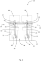
- the hydraulic pump system 10 includes a housing 12 defining a tank 14 for containing hydraulic fluid 16 in use.
- the hydraulic pump system also includes three pump modules 18 (one of which is obscured by the exploded/removed pump module 18 at the front of the figure). In alternative embodiments, more or fewer than three pump modules 18 are provided.
- Each pump module 18 includes a mounting portion 20 and a hydraulic pump 22 for supplying hydraulic fluid 16 from the tank 14 to a hydraulic system (e.g. a hydraulic system of a working vehicle).
- a hydraulic system e.g. a hydraulic system of a working vehicle.
- Each pump module 18 is mounted to the housing 12 by the mounting portion 20.
- Having pump modules 18 (i.e. attachable/detachable self-contained units) mounted to the housing 12 provides a self-contained hydraulic pump system 10 and reduces or removes the length of piping needed to connect the pumps 22 to the hydraulic fluid 16 contained in the tank 14. This reduces the complexity of the system and reduces or removes energy losses which would occur along such piping. This is particularly beneficial for working vehicles, such as battery-powered working vehicles where reduced energy losses result in increased battery life, or fuel cell powered working vehicles where reduced energy losses result in reduced fuel consumption. In addition, this arrangement is more compact than prior art systems in which the hydraulic pump(s) 22 are provided separate from the tank 14.
- the pump modules 18 are each attachable to and detachable from the housing as a self-contained unit. In other words, the pump modules 18 can each be installed or removed from the hydraulic pump system 10 without having to connect/disconnect interconnected components within the pump module 18.
- Each hydraulic pump 22 includes a body 24 having a pump inlet 26 and a pump outlet 28.
- the body 24 extends into the tank 14 so that the pump inlet 26 is immersed in hydraulic fluid 16 contained in the tank 14 in use.
- the body 24 extends partially into the tank 14.
- part of the body 24 e.g. an inlet portion
- the pump inlet 26 is not immersed in hydraulic fluid 16 contained in the tank 14 in use.
- the housing 12 defines three apertures 30 for receiving the pump modules 18.
- the mounting portion 20 of each pump module 18 is configured for mounting the pump module 18 around a respective aperture 30 of the housing 12. It will therefore be understood that where the number of pump modules 18 is more or less than in the illustrated embodiment, the number of apertures 30 differs accordingly. Having one or more apertures 30 for receiving the pump modules 18, and a mounting portion 20 on each pump module 18 provides a simple means for mounting the pump modules 18 to the housing 12.
- the mounting portion 20 of each pump module 18 includes a flange 32 for surrounding a perimeter of an aperture 30 of the housing 12 when the pump module 18 is coupled to the housing 12 in use. Having a flange 32 which surrounds a perimeter of an aperture 30 of the housing 12 allows the aperture 30 to be completely covered by the mounting portion 20 (which is useful for preventing ingress of dirt or debris, and/or leakage of fluid from the aperture 30). Such a flange 32 also provides an abutment surface which indicates when the pump module 18 has been correctly positioned relative to the housing 12.
- the mounting portion 20 of each pump module 18 includes a flange which only partially surrounds a perimeter of an aperture 30 of the housing 12.
- the mounting portion 20 includes a plurality of projections or flanges arranged circumferentially around an aperture 30 of the housing 12 in use.
- each pump module 18 is mounted to the housing 12 via a releasable fastening. Having a releasable fastening allows the pump modules 18 to be easily removed/installed for maintenance or replacement purposes.
- the mounting portion 20 includes a plurality of through-holes 34 and the housing 12 includes a corresponding plurality of threaded holes 36.
- Each through-hole 34 and threaded hole 36 is provided for receiving a bolt (not shown) to couple the pump module 18 to the housing 12 in use.
- the housing 12 includes a plurality of through-holes 34 and the mounting portion 20 includes a corresponding plurality of threaded holes 36.
- any other combination of through-holes and/or threaded holes suitable for receiving a fastener is used (e.g.
- through-hole shall be interpreted as a non-threaded hole
- threaded holes shall be interpreted as a blind or through-hole comprising threads.
- the mounting portion 20 of each pump module 18 is fixedly attached to the housing 12 (e.g. via welding or adhesive). Fixedly attaching the mounting portions 20 to the housing 12 ensures a robust connection and can contribute to sealing of the apertures 30 in which the pump modules 18 are received.
- the hydraulic pump system 10 includes seals for sealing the apertures 30 to prevent leakage of hydraulic fluid 16 from the tank 14.
- the apertures 30 being sealed in use allows the hydraulic pump system 10 to be used in any orientation (e.g. pump modules 18 can be mounted on a top, side or lower surface of the housing 12) without leakage of hydraulic fluid 16. This provides a more flexible range of uses for the hydraulic pump system 10.
- being sealed also prevents leakage in mobile applications where hydraulic fluid 16 may move around within the tank 14 (e.g. in a working vehicle due to acceleration forces or travelling over inclined surfaces).
- the mounting portion 20 of each pump module 18 includes a seal 38 for sealing a respective aperture 30 when the pump module 18 is coupled to the housing 12 in use.
- a seal 38 e.g. a compressible seal such as a gasket
- offers a reliable means of sealing an aperture 30, particularly under pressure e.g. a bolting pressure exerted on the compressible seal 38 when the mounting portion 20 is secured to the housing 12 via one or more bolts).
- each pump module 18 is provided on a lower surface of the mounting portion 20, so that the seal 38 is provided between the flange 32 and a portion of the housing 12 surrounding the aperture 30.
- the mounting portion 20 of each pump module 18 includes a seal surface instead of, or in addition to, the seal 38.
- a seal surface instead of, or in addition to, the seal 38.
- a flat metal surface intended to form a metal-to-metal seal with the housing when the mounting portion 20 is fixed to the housing under pressure (e.g. bolting pressure).
- the hydraulic pump system 10 also includes a plurality of hydraulic supply lines 40 each connected to a respective pump outlet 28 of the pump modules 18 for channelling hydraulic fluid 16 supplied by the pump modules 18 out of the housing 12.
- Such hydraulic supply lines 40 allow hydraulic fluid 16 supplied by the hydraulic pumps 22 to be used outside the tank 14 (e.g. to move actuators in a hydraulic system for a working vehicle).
- each pump module 18 includes one of the hydraulic supply lines 40 so that the hydraulic supply lines 40 can be attached/detached from the hydraulic pump system 10 with the respective pump module 18.
- Each of the hydraulic supply lines 40 being part of a respective pump module 18 allows simple removal/replacement of pump modules 18 without having to connect/disconnect the hydraulic supply line 40 from the associated pump outlet 28.
- each pump module 18 includes a hydraulic supply port 42 coupled to the hydraulic supply line 40 of the pump module 18 for connection to a hydraulic system in order to supply hydraulic fluid 16 from the pump module 18 to the hydraulic system.
- Each of the hydraulic supply ports 42 is arranged to be external to the tank 14 when its respective pump module 18 is mounted to the housing 12. Such a hydraulic supply port 42 allows the hydraulic pump modules 18 to be easily connected to a hydraulic system (e.g. for moving hydraulic actuators in a hydraulic system for a working vehicle).
- hydraulic supply ports 42 are provided on the housing 12 rather than the respective pump modules 18.
- each of the pump modules 18 also includes an electric motor 44 for driving the hydraulic pump 22 of the pump module 18.
- having an electric motor 44 for each pump module 18 allows flow of hydraulic fluid 16 from each module 18 to be controlled independently of the other modules 18. This allows optimal pump flow rates to be set for each pump module 18, in contrast to prior art hydraulic systems that are driven by an internal combustion engine (ICE) which results in the hydraulic pump(s) outputting hydraulic fluid whenever the ICE is running (even if not required by hydraulically actuated devices of the hydraulic system).
- ICE internal combustion engine
- having an electric motor for each pump module leads to improved efficiency of the hydraulic pump system 10, which is particularly beneficial for working vehicles, such as battery-powered working vehicles where increased pump system efficiency results in increased battery life, or fuel cell powered working vehicles where reduced energy losses result in reduced fuel consumption.
- the output of hydraulic fluid 16 from the hydraulic pump 22 of each of the pump modules 18 is controlled via rotation speed of the electric motor 44 of the pump module 18. Having the hydraulic pumps 22 controlled via rotation speed of the electric motors 44 allows an optimal pump flow rate to be set for each pump module 18. This reduces the need for restrictions in downstream hydraulic systems, which improves the efficiency of the associated hydraulic system.
- the hydraulic system also includes three inverters 46 to control frequency of power supplied to the electric motors 44 of the pump modules 18.
- Such an inverter arrangement enables variable speed control of the electric motors 44 and DC to AC power smoothing/conversion. This is useful in applications where the electric motors 44 are powered by a DC electricity source (e.g. a battery on an electric working vehicle or a fuel cell on a fuel cell powered vehicle).
- a DC electricity source e.g. a battery on an electric working vehicle or a fuel cell on a fuel cell powered vehicle.
- the inverters 46 are each part of a respective pump module 18 so that the inverter 46 can be attached/detached from the hydraulic pump system 10 with said pump module 18.
- the inverters 46 are provided separate to the pump modules 18.
- the electric motors 44 are DC motors and the inverters 46 are omitted.
- the hydraulic pump system 10 also includes a controller 48 configured to set the rotation speed of the electric motors 44 based on one or more user inputs 50 (such as an operating lever position) and/or one or more sensor inputs 52 (such as pump pressure and system temperature).
- a controller 48 allows an optimal pump flow rate to be set for each pump module 18, which leads to increased efficiency of a hydraulic system incorporating the hydraulic pump system 10.
- each pump module 18 is connected to the hydraulic pump 22 of the pump module 18 by a common drive shaft 54.
- Connecting a hydraulic pump 22 to an electric motor 44 via a common drive shaft 54 offers a simple and reliable means for driving the hydraulic pump 22 by the electric motor 44.
- the electric motor 44 of each pump module 18 is connected to the hydraulic pump 22 of the pump module 18 by a gearbox. Connecting a hydraulic pump 22 to an electric motor 44 via a gearbox allows the electric motor 44 and hydraulic pump 22 to each be run in their optimal rotational speed ranges (which may differ), which increases the efficiency of the hydraulic pump system 10.
- the electric motor 44 of each pump module 18 is arranged so that it is positioned external to the tank 14. Arranging the electric motors 44 to be external to the tank 14 protects electrical components from short-circuiting or other damage caused be contact with hydraulic fluid 16 located within the tank 14 in use.
- the hydraulic pump 22 of each pump module 18 is a fixed displacement pump.
- the hydraulic pumps 22 are bent axis piston pumps. Having an electric motor 44 driving a fixed displacement pump 22 eliminates the need for variable swash control to vary pump output, which allows an infinite range of output flow rates without inefficiency of partial displacement associated with variable swash plate piston pumps.
- bent axis piston pumps have been found to offer a high displacement ratio due to large swash angles (>40°), which results in a power dense package in comparison to axial piston pumps. This provides a high volumetric efficiency, which leads to an increased overall efficiency of the hydraulic pump system 10.
- the number of electric motors 44 is less than the number of pump modules 18, so that one or more pump modules are driven by a common electric motor 44.
- the electric motors 44 are omitted and the pump modules 18 are driven by an internal combustion engine.
- the output of hydraulic fluid 16 from the hydraulic pumps 22 of the pump modules 18 is variable for a given rotation rate of the common electric motor 44 or internal combustion engine (e.g. by using a variable swash-plate pump).
- a controller is provided to set the swash-plate angle (or similar displacement-changing property of the hydraulic pumps) based on one or more user inputs 50 and/or sensor inputs 52.
- the hydraulic pump system 10 also includes a filter arrangement 56 for filtering hydraulic fluid 16 input to the tank 14 (e.g. hydraulic fluid 16 returning from one or more hydraulically-actuated devices of a working vehicle). Having such a filter arrangement 56 removes debris entrained in the hydraulic fluid 16 prior to entering the tank 14 (e.g. debris formed via erosion of components in a hydraulic system) which improves the efficiency of the hydraulic system and reduces the likelihood of damage to components such as the hydraulic pump 22.
- the filter arrangement 56 is mounted on the housing 12 and extends partially into the tank 14 similarly to the pump modules 18, which provides a compact and self-contained arrangement.
- the filter arrangement 56 is provided external to the housing 12 (e.g. as a separate unit connected to the tank 14 via a pipe).
- the hydraulic pump system 10 may be used in different applications with different pump requirements. For example, in some embodiments only two pump modules 18 are required. In some embodiments where only two pump modules 18 are required, the housing 12 still includes three apertures 30 for receiving three pump modules 18. Therefore, one of the apertures 30 will not be covered by a pump module 18. In such embodiments, the aperture 30 which is not covered by the pump module 18 is covered by a cover plate of similar shape and size as the mounting portion 20 of the pump modules 18. In this way, the aperture 30 which is not covered by a pump module 18 is covered (and sealed, if the cover plate includes a seal) to prevent influx of debris to the tank 14 or leakage of hydraulic fluid 16 from the tank 14. Such a hydraulic pump system 10 is therefore configurable to meet the requirements of a particular application, by using the same basic integers (i.e. housing 12, pump modules 18 and cover plate).
- a hydraulic pump system according to a further embodiment is indicated at 210.
- Common features between the hydraulic pump system of Figures 1 to 4 and this embodiment are given the prefix "2", and only differences between the embodiments will be discussed in detail.
- the housing 212 includes an outer casing 212a and an inner liner 212b which defines an interior wall of the tank 214.
- the inner liner 212b is spaced apart from the outer casing 212a to define a cavity 213 therebetween (as best illustrated in Figures 6 and 7 ).
- the cavity 213 reduces the transmission of sound generated by the pumps 222 from within the tank 214 to an exterior of the housing 212.
- the cavity 213 contains sound absorbing material to further reduce the amount of noise generated by the pumps 222 that is transmitted to the exterior of the housing 212.
- the outer casing 212a has an open end defining a rim 258 and the inner liner 212b has an outwardly extending flange 260 for engaging the rim 258.
- the outwardly extending flange 260 prevents the inner liner 212b from dropping to the base of the outer casing 212a, so that the cavity 213 extends underneath the inner liner 212b.
- the inner liner 212b has a different type of outwardly extending projection instead of the flange 260 (e.g. a series of outwardly extending projections distributed around the inner liner 212b).
- the rim 258 of the outer casing 212a defines an inwardly extending flange which is configured to space the inner liner 212b from the side walls 262a of the outer casing 212a. In this way, the inwardly extending flange of the rim 258 extends to and abuts against the side walls 262b of the inner liner 212b, which ensures correct alignment of the inner liner 212b within the outer casing 212a.
- the rim 258 has a different type of inwardly extending projection instead of a flange (e.g. a series of inwardly extending projections distributed around the rim 258).
- separate spacing components are provided within the cavity 213 to facilitate spacing between the liner 212b and the outer casing 212a (e.g. in addition to, or instead of, the inwardly extending flange/projection(s) of the rim 258).
- the rim 258 is box shaped (i.e. formed of box sections welded to the side walls 262) and also extends outwardly from the side walls to provide a greater contact area for the flange 260 of the inner liner 212b and for the mounting plate 220.
- the inwardly extending flange of the rim 258 is formed by bending the side walls 262 inwards.
- the housing has an open upper end which defines an aperture 230 for receiving the pumps 222, as will be described in more detail below.
- the aperture 230 is closed by a mounting plate 220.
- the mounting plate 220 acts as a lid for the tank 214.
- mounting plate 220, flange 260 of the inner liner 212b and/or the rim 258 of the outer casing 212a can be clamped or welded together. While not shown in the illustrated embodiment, mounting plate 220, flange 260 of the inner liner 212b and/or the rim 258 of the outer casing 212a can also be attached by fasteners (e.g. bolts) provided in complementary through-holes or threaded holes in the mounting plate 220, flange 260 of the inner liner 212b and/or rim 258 of the outer casing 212a. It will be understood that in some embodiments with such through-holes or threaded holes, the outwardly extending portion of the rim 258 is extended to provide space for the holes to receive the fasteners.
- fasteners e.g. bolts
- a seal (not shown) is provided between the mounting plate 220 and the housing 212.
- a compressible seal such as a gasket is attached to an underside of the mounting plate 220 or attached to a top of the flange 260 of the inner liner 212b.
- a compressible seal is provided as a separate component that is placed between the mounting plate 220 and housing 212 during assembly.
- the seal also has holes aligned with through-holes or threaded holes of the mounting plate 220 and housing 212 to receive a fastener (e.g. bolt) therethrough.
- the outer casing 212a can be formed of plastics material, metallic material (e.g. steel or aluminium) or any other suitable material.
- the inner liner 212b can be formed of plastics material, metallic material (e.g. steel or aluminium) or any other suitable material.
- the mounting plate 220 is configured to mount all of the pumps 222 to the housing 212.
- the pump module 218 includes the mounting plate 220, the three pumps 222, and their respective motors 244 and inverters 246, so that all the pumps 222, motors 244 and inverters 246 are installed/removed from the housing 212 together.
- the hydraulic supply lines 240 each extend from a respective pump outlet 228 to a respective port 242 provided on the common mounting plate 220.
- the pumps 222 and their respective motors 244 and inverters 246 are additionally releasably mounted to the mounting plate 220 so that they can be removed/replaced independently of each other.
- the pumps 222 and their respective motors 244 and inverters 246 are additionally releasably mounted to the mounting plate 220 so that they can be removed/replaced independently of each other.
- several pump modules 18 are attached to a common mounting plate 220 by individual mounting portions 20, in the same way that the pump modules 18 of the embodiment of Figures 1 to 4 above are attached to an upper surface of the housing 12.
- the mounting plate 220 extends beyond the area defined by the open end of the housing 212 (e.g. behind the housing 212). In this way, the mounting plate 220 provides a shoulder 264 which can be used to mount the hydraulic pump system 210 to a vehicle.
- the portion of the mounting plate 220 which extends beyond the area defined by the open end of the housing 212 also provides space for mounting additional components such as electronics, filters or the like.
- a cover 266 is provided for the components which are external to the tank 214 (i.e. electric motors 244, inverters 246 and other electronics).
- the cover 266 protects such components from impact, dirt and debris, and also reduces the transmission of noise generated by these components, which results in a quieter pump system 210.
- cover 266 would include one or more suitable apertures, cutaways or the like for access to the hydraulic ports 242 (e.g. to connect hoses thereto).
- the cover 266 includes sound-absorbing material (e.g. lined on an inside of the cover 266).
- the cover 266 can be formed of plastics material, metallic material (e.g. steel or aluminium) or any other suitable material.
- the mounting plate 220 includes a slot 268 for allowing airflow inside the cover 266 (e.g. for cooling the electronic components located therein).
- a slot 268 is provided in the cover 266, or a plurality of such slots 268 are provided in the mounting plate 220 and/or cover 266.
- the working vehicle 100 includes a working arm 102 controlled by a plurality of hydraulic actuators 104.
- the working vehicle 100 also includes a pair of left and right tracks 106 for moving the working vehicle 100.
- the left and right tracks 106 are driven by respective hydraulic motors.
- a set of user inputs 50 e.g. joy-sticks, levers, buttons, pedals etc.
- the working vehicle 100 also includes a hydraulic pump system 10 as described above in relation to Figures 1 to 4 or a hydraulic pump system 210 as described above in relation to Figures 5 to 8 .
- the hydraulic pump system 10, 210 is provided to supply hydraulic fluid 16 to the hydraulic actuators 104 and left/right track motors of the working vehicle 100.
- the hydraulic pump systems 10, 210 of Figures 1 to 4 and 5 to 8 are particularly compact and efficient. This provides significant benefits when applied to a working vehicle 100 (where space is restricted and power is of limited capacity), particularly when the working vehicle 100 is an electric working vehicle where increased efficiency results in increased battery life and periods of use between charging, or a fuel cell powered working vehicle where reduced energy losses result in reduced fuel consumption.
- the working vehicle 100 is of the type known as an excavator.
- the working vehicle is a different type of vehicle.
- the working vehicle is a backhoe loader, telehandler, skid-steer loader, dumper, forklift truck or other type of working vehicle having one or more hydraulically-actuated devices.
- the hydraulic pump system 10, 210 is part of a hydraulic system of a static application rather than a mobile application such as a working vehicle (e.g. the hydraulic pump system 10, 210 is part of an industrial hydraulic system in a manufacturing or processing plant).
- module used throughout this description is to be interpreted as an attachable/detachable self-contained unit comprising components that can be installed in or removed from the hydraulic pump system 10 as a single unit, i.e. without having to connect/disconnect interconnected components of the module to or from one another.
Landscapes
- Engineering & Computer Science (AREA)
- General Engineering & Computer Science (AREA)
- Mechanical Engineering (AREA)
- Mining & Mineral Resources (AREA)
- Civil Engineering (AREA)
- Structural Engineering (AREA)
- Physics & Mathematics (AREA)
- Fluid Mechanics (AREA)
- Chemical & Material Sciences (AREA)
- Analytical Chemistry (AREA)
- Details Of Reciprocating Pumps (AREA)
- Supply Devices, Intensifiers, Converters, And Telemotors (AREA)
Claims (15)
- Arbeitsfahrzeug mit einem hydraulischen Pumpensystem (10, 210), das hydraulische Pumpensystem umfassend:ein Gehäuse (12, 212), das im Gebrauch einen Tank (214) zur Aufnahme von Hydraulikflüssigkeit (216) definiert,ein oder mehrere Pumpenmodule (18, 218), die jeweils eine Hydraulikpumpe (22, 222) zum Zuführen von Hydraulikflüssigkeit aus dem Tank zu einem Hydrauliksystem umfassen, undeine Montageanordnung (20, 220),wobei das oder jedes Pumpenmodul durch die Montageanordnung am Gehäuse befestigt ist, unddadurch gekennzeichnet, dass das eine oder die mehreren Pumpenmodule drei hydraulische Pumpen umfassen.
- Arbeitsfahrzeug nach Anspruch 1, wobei die Montageanordnung einen einzelnen Montageabschnitt (220) (z. B. Montageplatte) umfasst und jede Hydraulikpumpe über den einzelnen Montageabschnitt am Gehäuse befestigt ist, oder wobei die Montageanordnung eine Vielzahl von Montageabschnitten (20) umfasst und jede Hydraulikpumpe über einen der Montageabschnitte am Gehäuse befestigt ist.
- Arbeitsfahrzeug nach Anspruch 1 oder 2, wobei die oder jede Hydraulikpumpe einen Körper (24) umfasst und wobei sich der Körper zumindest teilweise in den Tank erstreckt.
- Arbeitsfahrzeug nach Anspruch 3, wobei das Gehäuse ein Außengehäuse (212a) und eine Innenauskleidung (212b) umfasst, die vom Außengehäuse beabstandet ist, um dazwischen einen Hohlraum (213) zu definieren, wobei der Hohlraum optional schallabsorbierendes Material enthält.
- Arbeitsfahrzeug nach einem der vorhergehenden Ansprüche, wobei das Gehäuse eine oder mehrere Öffnungen (30, 230) zur Aufnahme des einen oder der mehreren Pumpenmodule definiert und wobei die Montageanordnung eine oder mehrere Platten (220) oder Flansche (32) umfasst, die jeweils zumindest teilweise einen Umfangs einer der einen oder mehreren Öffnungen des Gehäuses umgeben.
- Arbeitsfahrzeug nach einem der vorhergehenden Ansprüche, wobei die Montageanordnung über eine lösbare Befestigung am Gehäuse befestigt ist, wobei optional entweder die Montageanordnung oder das Gehäuse ein oder mehrere Durchgangslöcher (34) oder Gewindelöcher (36) aufweist und der andere vom Montageabschnitt und Gehäuse ein oder mehrere entsprechende Durchgangslöcher (34) oder Gewindelöcher (36) umfasst, wobei das oder jedes Durchgangsloch und Gewindeloch zur Aufnahme eines Bolzens zum Koppeln der Montageanordnung am Gehäuse vorgesehen ist.
- Arbeitsfahrzeug nach Anspruch 5 oder 6, ferner umfassend eine oder mehrere Dichtungen (38) zum Abdichten der einen oder mehreren Öffnungen, wobei die Montageanordnung optional eine oder mehrere Montageplatten oder Montageflansche umfasst, die eine jeweilige Öffnung der einen oder mehreren Öffnungen des Gehäuses zumindest teilweise umgeben, und wobei die oder jede Montageplatte oder der oder jeder Montageflansch ferner eine Dichtungsfläche und/oder Dichtung umfasst, die auf der Montageplatte oder dem Montageflansch zum Abdichten der Öffnung vorgesehen ist.
- Arbeitsfahrzeug nach einem der vorhergehenden Ansprüche, wobei jedes der einen oder mehreren Pumpenmodule einen Körper umfasst, der einen Einlassabschnitt umfasst, der einen Pumpeneinlass (26, 226) definiert, undwobei sich der Einlassabschnitt des Körpers so in den Tank erstreckt, dass der Pumpeneinlass im Betrieb in die im Tank enthaltene Hydraulikflüssigkeit eintaucht und/oderwobei das hydraulische Pumpensystem ferner eine Filter- oder Siebanordnung (56) umfasst, die mit dem Pumpeneinlass gekoppelt ist, wobei sich der Einlassabschnitt des Körpers in den Tank erstreckt, so dass die Filter- oder Siebanordnung im Betrieb in die im Tank enthaltene Hydraulikflüssigkeit eintaucht.
- Arbeitsfahrzeug nach Anspruch 8, wobei jedes der einen oder mehreren Pumpenmodule einen Pumpenauslass (28, 228) umfasst und wobei das hydraulische Pumpensystem ferner eine oder mehrere damit verbundene hydraulische Versorgungsleitungen (40, 240) umfasst, die mit der einen oder den mehreren Pumpenauslässen verbunden sind, um Hydraulikflüssigkeit, die von dem einen oder den mehreren Pumpenmodulen zugeführt wird, aus dem Gehäuse zu leiten.
- Arbeitsfahrzeug nach Anspruch 9, wobei jede der hydraulischen Versorgungsleitungen mit der Montageanordnung gekoppelt ist, so dass die hydraulischen Versorgungsleitungen optional mit dem hydraulischen Pumpensystem mit den jeweiligen Pumpenmodulen verbunden bzw. davon gelöst werden können, wobei die Montageanordnung einen oder mehrere Hydraulikversorgungsanschlüsse (42, 242) umfasst, die jeweils mit einer entsprechenden Hydraulikversorgungsleitung zum Anschluss an ein Hydrauliksystem verbunden sind, um dem Hydrauliksystem Hydraulikflüssigkeit von dem einen oder den mehreren Pumpenmodulen zuzuführen, wobei der oder jeder hydraulische Versorgungsanschluss außerhalb des Tanks angeordnet ist.
- Arbeitsfahrzeug nach einem der vorhergehenden Ansprüche, wobei jedes der einen oder mehreren Pumpenmodule ferner einen Elektromotor (44, 244) zum Antreiben der Hydraulikpumpe umfasst, wobei optional die Abgabe von Hydraulikflüssigkeit von der Hydraulikpumpe von jeder der einen oder der mehreren Pumpenmodule über die Drehzahl des Elektromotors des Pumpenmoduls gesteuert wird, wobei optional das Hydrauliksystem ferner einen oder mehrere Wechselrichter (46, 246) zum Steuern der Frequenz des Stroms umfasst, der dem einen oder den mehreren Pumpenmodulen zugeführt wird, wobei optional der eine oder die mehreren Wechselrichter jeweils an der Montageanordnung oder an einem entsprechenden Pumpenmodul befestigt sind, so dass der eine oder die mehreren Wechselrichter an dem hydraulischen Pumpensystem mit dem einen oder den mehreren Pumpenmodulen angebracht bzw. davon entfernt werden können und/oder optional ferner umfassend eine Steuerung (48), die dazu beschaffen ist, die Drehzahl des oder jedes Elektromotors basierend auf einer oder mehreren Benutzereingaben (50) und/oder einer oder mehreren Sensoreingaben (52), wie etwa Pumpendruck und Systemtemperatur, einzustellen, wobei optional der Elektromotor und/oder Wechselrichter von mindestens einem des einen oder der mehreren Pumpenmodule dazu beschaffen ist, außerhalb des Tanks angeordnet zu werden, wobei optional das hydraulische Pumpensystem ferner eine Abdeckung (266) für den (die) Elektromotor(en) und/oder den oder die Wechselrichter umfasst.
- Arbeitsfahrzeug nach einem der vorhergehenden Ansprüche, wobei die Hydraulikpumpe jedes der einen oder mehreren Pumpenmodule eine Konstantpumpe ist, wobei die Hydraulikpumpe jedes des einen oder der mehreren Pumpenmodule optional eine Schrägachsenkolbenpumpe ist.
- Arbeitsfahrzeug nach einem der vorhergehenden Ansprüche, wobei das Arbeitsfahrzeug ein Elektro-Arbeitsfahrzeug ist.
- Arbeitsfahrzeug nach einem der Ansprüche 1 bis 12, wobei das Arbeitsfahrzeug ein brennstoffzellenbetriebenes Arbeitsfahrzeug ist.
- Arbeitsfahrzeug nach einem der Ansprüche 1 bis 12, wobei das Arbeitsfahrzeug ein Hybrid-Arbeitsfahrzeug der Art ist, das eine elektrische Energiequelle und eine alternative Energiequelle aufweist.
Priority Applications (1)
| Application Number | Priority Date | Filing Date | Title |
|---|---|---|---|
| EP24175974.5A EP4397860A3 (de) | 2021-03-08 | 2022-03-02 | Hydraulisches pumpensystem |
Applications Claiming Priority (1)
| Application Number | Priority Date | Filing Date | Title |
|---|---|---|---|
| GB2103209.9A GB2604609A (en) | 2021-03-08 | 2021-03-08 | Hydraulic pump system |
Related Child Applications (2)
| Application Number | Title | Priority Date | Filing Date |
|---|---|---|---|
| EP24175974.5A Division EP4397860A3 (de) | 2021-03-08 | 2022-03-02 | Hydraulisches pumpensystem |
| EP24175974.5A Division-Into EP4397860A3 (de) | 2021-03-08 | 2022-03-02 | Hydraulisches pumpensystem |
Publications (2)
| Publication Number | Publication Date |
|---|---|
| EP4056847A1 EP4056847A1 (de) | 2022-09-14 |
| EP4056847B1 true EP4056847B1 (de) | 2024-06-19 |
Family
ID=75472583
Family Applications (2)
| Application Number | Title | Priority Date | Filing Date |
|---|---|---|---|
| EP22275025.9A Active EP4056847B1 (de) | 2021-03-08 | 2022-03-02 | Hydraulikpumpensystem |
| EP24175974.5A Pending EP4397860A3 (de) | 2021-03-08 | 2022-03-02 | Hydraulisches pumpensystem |
Family Applications After (1)
| Application Number | Title | Priority Date | Filing Date |
|---|---|---|---|
| EP24175974.5A Pending EP4397860A3 (de) | 2021-03-08 | 2022-03-02 | Hydraulisches pumpensystem |
Country Status (5)
| Country | Link |
|---|---|
| US (1) | US12180948B2 (de) |
| EP (2) | EP4056847B1 (de) |
| CN (1) | CN115045870A (de) |
| BR (1) | BR102022004254A2 (de) |
| GB (1) | GB2604609A (de) |
Families Citing this family (4)
| Publication number | Priority date | Publication date | Assignee | Title |
|---|---|---|---|---|
| FR3107572B1 (fr) * | 2020-02-21 | 2022-02-25 | Air Liquide | Appareil de compression et station de remplissage comprenant un tel appareil |
| EP4306724A1 (de) | 2022-07-15 | 2024-01-17 | Yanmar Holdings Co., Ltd. | Elektrische arbeitsmaschine |
| US20240240658A1 (en) * | 2023-01-17 | 2024-07-18 | Narendra Gupta | Hydraulic power pack module |
| GB2629410A (en) | 2023-04-27 | 2024-10-30 | Bamford Excavators Ltd | A hydraulic pump arrangement |
Family Cites Families (26)
| Publication number | Priority date | Publication date | Assignee | Title |
|---|---|---|---|---|
| US2456339A (en) * | 1946-06-25 | 1948-12-14 | Darwin B Stricklin | Pump construction |
| US3212280A (en) * | 1963-11-22 | 1965-10-19 | Air Prod & Chem | Volatile liquid pumping system |
| US4047845A (en) * | 1975-12-22 | 1977-09-13 | Auto Research Corporation | Cyclic pump |
| KR970001727B1 (ko) | 1991-04-12 | 1997-02-14 | 히다찌 겐끼 가부시기가이샤 | 건설기계의 유압구동장치 |
| DE4120665A1 (de) * | 1991-06-22 | 1992-12-24 | Teves Gmbh Alfred | Elektromotorisch angetriebene hydraulikpumpe |
| DE19612582A1 (de) * | 1996-03-29 | 1997-10-02 | Miag Fahrzeugbau Gmbh | Antriebseinheit für ein Fahrzeug |
| EP0857871B1 (de) * | 1997-02-05 | 2001-11-07 | Hoerbiger Hydraulik GmbH | Hydraulisches Motorpumpenaggregat |
| DE19959022C1 (de) * | 1999-12-08 | 2001-06-21 | Bosch Gmbh Robert | Antriebseinheit |
| KR100621985B1 (ko) | 2005-08-02 | 2006-09-11 | 볼보 컨스트럭션 이키프먼트 홀딩 스웨덴 에이비 | 주행시스템 |
| US7513393B2 (en) * | 2006-06-16 | 2009-04-07 | Lincoln Industrial Corporation | Container system |
| DE102011106307A1 (de) | 2011-07-01 | 2013-01-03 | Robert Bosch Gmbh | Steueranordnung und Verfahren zum Ansteuern von mehreren hydraulischen Verbrauchern |
| US9239044B2 (en) * | 2012-03-19 | 2016-01-19 | Lincoln Industrial Corporation | Lance pump having horizontally mounted stepper/servo motor |
| US9145660B2 (en) | 2012-08-31 | 2015-09-29 | Caterpillar Inc. | Hydraulic control system having over-pressure protection |
| US9303387B2 (en) | 2012-11-01 | 2016-04-05 | Husco International, Inc. | Hydraulic system with open loop electrohydraulic pressure compensation |
| JP6147229B2 (ja) * | 2014-07-02 | 2017-06-14 | 日精樹脂工業株式会社 | 電動ポンプ装置 |
| JP6324347B2 (ja) | 2015-06-01 | 2018-05-16 | 日立建機株式会社 | 建設機械の油圧制御装置 |
| EP3358201B1 (de) | 2015-09-29 | 2023-02-15 | Hitachi Construction Machinery Co., Ltd. | Druckölenergierückgewinnungsvorrichtung einer arbeitsmaschine |
| DE102015119055B4 (de) * | 2015-11-06 | 2019-05-09 | Knorr-Bremse Systeme für Schienenfahrzeuge GmbH | Hydrogerät |
| CN107407300B (zh) | 2016-03-10 | 2018-12-28 | 日立建机株式会社 | 工程机械 |
| WO2018140905A1 (en) * | 2017-01-27 | 2018-08-02 | Franklin Electric Co., Inc. | Motor drive system and method |
| JP6596458B2 (ja) | 2017-03-13 | 2019-10-23 | 株式会社日立建機ティエラ | 電動式油圧作業機械の油圧駆動装置 |
| CN109563696B (zh) * | 2017-05-09 | 2021-05-07 | 日立建机株式会社 | 作业机械 |
| JP6450487B1 (ja) | 2018-05-15 | 2019-01-09 | 川崎重工業株式会社 | 油圧ショベル駆動システム |
| JP6867551B2 (ja) | 2018-09-05 | 2021-04-28 | 株式会社日立建機ティエラ | 電動式油圧作業機械の油圧駆動装置 |
| DE102019003342A1 (de) * | 2019-05-11 | 2020-11-12 | Hydac Fluidtechnik Gmbh | Hydraulisches Antriebssystem |
| EP3779209B1 (de) * | 2019-08-16 | 2023-09-20 | Bucher Municipal AG | Auf einer festen bodenoberfläche selbstfahrende arbeitsmaschine mit einem auf einem fahrgestell aufgebauten hydraulikaggregat |
-
2021
- 2021-03-08 GB GB2103209.9A patent/GB2604609A/en active Pending
-
2022
- 2022-03-02 EP EP22275025.9A patent/EP4056847B1/de active Active
- 2022-03-02 EP EP24175974.5A patent/EP4397860A3/de active Pending
- 2022-03-08 BR BR102022004254-3A patent/BR102022004254A2/pt unknown
- 2022-03-08 CN CN202210220579.7A patent/CN115045870A/zh active Pending
- 2022-03-08 US US17/689,980 patent/US12180948B2/en active Active
Also Published As
| Publication number | Publication date |
|---|---|
| CN115045870A (zh) | 2022-09-13 |
| EP4056847A1 (de) | 2022-09-14 |
| US12180948B2 (en) | 2024-12-31 |
| GB2604609A (en) | 2022-09-14 |
| EP4397860A3 (de) | 2024-09-25 |
| US20220282718A1 (en) | 2022-09-08 |
| BR102022004254A2 (pt) | 2022-09-20 |
| GB202103209D0 (en) | 2021-04-21 |
| EP4397860A2 (de) | 2024-07-10 |
Similar Documents
| Publication | Publication Date | Title |
|---|---|---|
| EP4056847B1 (de) | Hydraulikpumpensystem | |
| KR101342565B1 (ko) | 작업 기계의 전액 구동 시스템 | |
| US6912849B2 (en) | Cylinder driving system and energy regenerating method thereof | |
| RU2429148C2 (ru) | Компрессорное устройство | |
| US5540563A (en) | Unitary housing for double hydraulic unit | |
| US9790662B2 (en) | Hybrid-type working machine | |
| JP4873058B2 (ja) | 車両用自動変速機 | |
| CN114987130A (zh) | Mpe车轴组的外壳结构 | |
| US10919376B2 (en) | Recess-mounted hydraulic pump cartridge and work vehicle drivetrain therewith | |
| WO2016000732A1 (en) | A turbocharger unit | |
| US4467604A (en) | Hydrostatic drive system for an excavator | |
| CN212003821U (zh) | 多功能独立散热系统 | |
| KR101804437B1 (ko) | 개구 폐색 커버 및 당해 개구 폐색 커버를 구비한 건설기계 | |
| CN217421714U (zh) | 一种液压系统动力元件并联装置 | |
| CN215890441U (zh) | 一种带吸油滤清器的电油泵 | |
| JP2019173943A (ja) | 車両用駆動装置 | |
| CN111336160A (zh) | 散热系统及工程机械装备 | |
| EP4455480A1 (de) | Hydraulische pumpenanordnung | |
| CN220483085U (zh) | 一种挖掘装载机油箱组合结构 | |
| JP4783488B2 (ja) | 潤滑油供給装置およびそのラインフィルタ | |
| US20100146960A1 (en) | Externally mounted variator for split torque transmission | |
| CN216044388U (zh) | 一种可变量低脉动齿轮泵 | |
| CN219802012U (zh) | 带有电动马达的系统 | |
| CN1281867C (zh) | 机械泵 | |
| CN215595878U (zh) | 一种驱动液压齿轮泵的电机装置 |
Legal Events
| Date | Code | Title | Description |
|---|---|---|---|
| PUAI | Public reference made under article 153(3) epc to a published international application that has entered the european phase |
Free format text: ORIGINAL CODE: 0009012 |
|
| STAA | Information on the status of an ep patent application or granted ep patent |
Free format text: STATUS: THE APPLICATION HAS BEEN PUBLISHED |
|
| AK | Designated contracting states |
Kind code of ref document: A1 Designated state(s): AL AT BE BG CH CY CZ DE DK EE ES FI FR GB GR HR HU IE IS IT LI LT LU LV MC MK MT NL NO PL PT RO RS SE SI SK SM TR |
|
| STAA | Information on the status of an ep patent application or granted ep patent |
Free format text: STATUS: REQUEST FOR EXAMINATION WAS MADE |
|
| 17P | Request for examination filed |
Effective date: 20230314 |
|
| RBV | Designated contracting states (corrected) |
Designated state(s): AL AT BE BG CH CY CZ DE DK EE ES FI FR GB GR HR HU IE IS IT LI LT LU LV MC MK MT NL NO PL PT RO RS SE SI SK SM TR |
|
| GRAP | Despatch of communication of intention to grant a patent |
Free format text: ORIGINAL CODE: EPIDOSNIGR1 |
|
| STAA | Information on the status of an ep patent application or granted ep patent |
Free format text: STATUS: GRANT OF PATENT IS INTENDED |
|
| RIC1 | Information provided on ipc code assigned before grant |
Ipc: F04B 23/04 20060101ALI20240112BHEP Ipc: F04B 23/02 20060101ALI20240112BHEP Ipc: F04B 17/03 20060101AFI20240112BHEP |
|
| INTG | Intention to grant announced |
Effective date: 20240220 |
|
| GRAS | Grant fee paid |
Free format text: ORIGINAL CODE: EPIDOSNIGR3 |
|
| GRAA | (expected) grant |
Free format text: ORIGINAL CODE: 0009210 |
|
| STAA | Information on the status of an ep patent application or granted ep patent |
Free format text: STATUS: THE PATENT HAS BEEN GRANTED |
|
| P01 | Opt-out of the competence of the unified patent court (upc) registered |
Effective date: 20240501 |
|
| AK | Designated contracting states |
Kind code of ref document: B1 Designated state(s): AL AT BE BG CH CY CZ DE DK EE ES FI FR GB GR HR HU IE IS IT LI LT LU LV MC MK MT NL NO PL PT RO RS SE SI SK SM TR |
|
| REG | Reference to a national code |
Ref country code: GB Ref legal event code: FG4D |
|
| REG | Reference to a national code |
Ref country code: CH Ref legal event code: EP |
|
| REG | Reference to a national code |
Ref country code: DE Ref legal event code: R096 Ref document number: 602022004045 Country of ref document: DE |
|
| REG | Reference to a national code |
Ref country code: SE Ref legal event code: TRGR |
|
| PG25 | Lapsed in a contracting state [announced via postgrant information from national office to epo] |
Ref country code: BG Free format text: LAPSE BECAUSE OF FAILURE TO SUBMIT A TRANSLATION OF THE DESCRIPTION OR TO PAY THE FEE WITHIN THE PRESCRIBED TIME-LIMIT Effective date: 20240619 |
|
| PG25 | Lapsed in a contracting state [announced via postgrant information from national office to epo] |
Ref country code: FI Free format text: LAPSE BECAUSE OF FAILURE TO SUBMIT A TRANSLATION OF THE DESCRIPTION OR TO PAY THE FEE WITHIN THE PRESCRIBED TIME-LIMIT Effective date: 20240619 Ref country code: HR Free format text: LAPSE BECAUSE OF FAILURE TO SUBMIT A TRANSLATION OF THE DESCRIPTION OR TO PAY THE FEE WITHIN THE PRESCRIBED TIME-LIMIT Effective date: 20240619 |
|
| REG | Reference to a national code |
Ref country code: LT Ref legal event code: MG9D |
|
| PG25 | Lapsed in a contracting state [announced via postgrant information from national office to epo] |
Ref country code: GR Free format text: LAPSE BECAUSE OF FAILURE TO SUBMIT A TRANSLATION OF THE DESCRIPTION OR TO PAY THE FEE WITHIN THE PRESCRIBED TIME-LIMIT Effective date: 20240920 |
|
| REG | Reference to a national code |
Ref country code: NL Ref legal event code: MP Effective date: 20240619 |
|
| PG25 | Lapsed in a contracting state [announced via postgrant information from national office to epo] |
Ref country code: LV Free format text: LAPSE BECAUSE OF FAILURE TO SUBMIT A TRANSLATION OF THE DESCRIPTION OR TO PAY THE FEE WITHIN THE PRESCRIBED TIME-LIMIT Effective date: 20240619 |
|
| PG25 | Lapsed in a contracting state [announced via postgrant information from national office to epo] |
Ref country code: NO Free format text: LAPSE BECAUSE OF FAILURE TO SUBMIT A TRANSLATION OF THE DESCRIPTION OR TO PAY THE FEE WITHIN THE PRESCRIBED TIME-LIMIT Effective date: 20240919 Ref country code: LV Free format text: LAPSE BECAUSE OF FAILURE TO SUBMIT A TRANSLATION OF THE DESCRIPTION OR TO PAY THE FEE WITHIN THE PRESCRIBED TIME-LIMIT Effective date: 20240619 Ref country code: HR Free format text: LAPSE BECAUSE OF FAILURE TO SUBMIT A TRANSLATION OF THE DESCRIPTION OR TO PAY THE FEE WITHIN THE PRESCRIBED TIME-LIMIT Effective date: 20240619 Ref country code: GR Free format text: LAPSE BECAUSE OF FAILURE TO SUBMIT A TRANSLATION OF THE DESCRIPTION OR TO PAY THE FEE WITHIN THE PRESCRIBED TIME-LIMIT Effective date: 20240920 Ref country code: FI Free format text: LAPSE BECAUSE OF FAILURE TO SUBMIT A TRANSLATION OF THE DESCRIPTION OR TO PAY THE FEE WITHIN THE PRESCRIBED TIME-LIMIT Effective date: 20240619 Ref country code: BG Free format text: LAPSE BECAUSE OF FAILURE TO SUBMIT A TRANSLATION OF THE DESCRIPTION OR TO PAY THE FEE WITHIN THE PRESCRIBED TIME-LIMIT Effective date: 20240619 Ref country code: RS Free format text: LAPSE BECAUSE OF FAILURE TO SUBMIT A TRANSLATION OF THE DESCRIPTION OR TO PAY THE FEE WITHIN THE PRESCRIBED TIME-LIMIT Effective date: 20240919 |
|
| PG25 | Lapsed in a contracting state [announced via postgrant information from national office to epo] |
Ref country code: NL Free format text: LAPSE BECAUSE OF FAILURE TO SUBMIT A TRANSLATION OF THE DESCRIPTION OR TO PAY THE FEE WITHIN THE PRESCRIBED TIME-LIMIT Effective date: 20240619 |
|
| REG | Reference to a national code |
Ref country code: AT Ref legal event code: MK05 Ref document number: 1696065 Country of ref document: AT Kind code of ref document: T Effective date: 20240619 |
|
| PG25 | Lapsed in a contracting state [announced via postgrant information from national office to epo] |
Ref country code: NL Free format text: LAPSE BECAUSE OF FAILURE TO SUBMIT A TRANSLATION OF THE DESCRIPTION OR TO PAY THE FEE WITHIN THE PRESCRIBED TIME-LIMIT Effective date: 20240619 |
|
| PG25 | Lapsed in a contracting state [announced via postgrant information from national office to epo] |
Ref country code: PT Free format text: LAPSE BECAUSE OF FAILURE TO SUBMIT A TRANSLATION OF THE DESCRIPTION OR TO PAY THE FEE WITHIN THE PRESCRIBED TIME-LIMIT Effective date: 20241021 |
|
| PG25 | Lapsed in a contracting state [announced via postgrant information from national office to epo] |
Ref country code: PT Free format text: LAPSE BECAUSE OF FAILURE TO SUBMIT A TRANSLATION OF THE DESCRIPTION OR TO PAY THE FEE WITHIN THE PRESCRIBED TIME-LIMIT Effective date: 20241021 |
|
| PG25 | Lapsed in a contracting state [announced via postgrant information from national office to epo] |
Ref country code: PL Free format text: LAPSE BECAUSE OF FAILURE TO SUBMIT A TRANSLATION OF THE DESCRIPTION OR TO PAY THE FEE WITHIN THE PRESCRIBED TIME-LIMIT Effective date: 20240619 |
|
| PG25 | Lapsed in a contracting state [announced via postgrant information from national office to epo] |
Ref country code: EE Free format text: LAPSE BECAUSE OF FAILURE TO SUBMIT A TRANSLATION OF THE DESCRIPTION OR TO PAY THE FEE WITHIN THE PRESCRIBED TIME-LIMIT Effective date: 20240619 |
|
| PG25 | Lapsed in a contracting state [announced via postgrant information from national office to epo] |
Ref country code: IS Free format text: LAPSE BECAUSE OF FAILURE TO SUBMIT A TRANSLATION OF THE DESCRIPTION OR TO PAY THE FEE WITHIN THE PRESCRIBED TIME-LIMIT Effective date: 20241019 Ref country code: AT Free format text: LAPSE BECAUSE OF FAILURE TO SUBMIT A TRANSLATION OF THE DESCRIPTION OR TO PAY THE FEE WITHIN THE PRESCRIBED TIME-LIMIT Effective date: 20240619 |
|
| PG25 | Lapsed in a contracting state [announced via postgrant information from national office to epo] |
Ref country code: CZ Free format text: LAPSE BECAUSE OF FAILURE TO SUBMIT A TRANSLATION OF THE DESCRIPTION OR TO PAY THE FEE WITHIN THE PRESCRIBED TIME-LIMIT Effective date: 20240619 |
|
| PG25 | Lapsed in a contracting state [announced via postgrant information from national office to epo] |
Ref country code: SK Free format text: LAPSE BECAUSE OF FAILURE TO SUBMIT A TRANSLATION OF THE DESCRIPTION OR TO PAY THE FEE WITHIN THE PRESCRIBED TIME-LIMIT Effective date: 20240619 Ref country code: RO Free format text: LAPSE BECAUSE OF FAILURE TO SUBMIT A TRANSLATION OF THE DESCRIPTION OR TO PAY THE FEE WITHIN THE PRESCRIBED TIME-LIMIT Effective date: 20240619 |
|
| PG25 | Lapsed in a contracting state [announced via postgrant information from national office to epo] |
Ref country code: ES Free format text: LAPSE BECAUSE OF FAILURE TO SUBMIT A TRANSLATION OF THE DESCRIPTION OR TO PAY THE FEE WITHIN THE PRESCRIBED TIME-LIMIT Effective date: 20240619 Ref country code: SM Free format text: LAPSE BECAUSE OF FAILURE TO SUBMIT A TRANSLATION OF THE DESCRIPTION OR TO PAY THE FEE WITHIN THE PRESCRIBED TIME-LIMIT Effective date: 20240619 |