EP4056428A1 - Verfahren zur herstellung einer dekormatte für den innenraum eines fahrzeugs - Google Patents
Verfahren zur herstellung einer dekormatte für den innenraum eines fahrzeugs Download PDFInfo
- Publication number
- EP4056428A1 EP4056428A1 EP22161457.1A EP22161457A EP4056428A1 EP 4056428 A1 EP4056428 A1 EP 4056428A1 EP 22161457 A EP22161457 A EP 22161457A EP 4056428 A1 EP4056428 A1 EP 4056428A1
- Authority
- EP
- European Patent Office
- Prior art keywords
- strips
- covering
- decoration
- flaps
- flap
- Prior art date
- Legal status (The legal status is an assumption and is not a legal conclusion. Google has not performed a legal analysis and makes no representation as to the accuracy of the status listed.)
- Pending
Links
- 238000000034 method Methods 0.000 title claims abstract description 32
- 238000004519 manufacturing process Methods 0.000 title claims abstract description 8
- 239000000463 material Substances 0.000 claims abstract description 73
- 238000005034 decoration Methods 0.000 claims abstract description 27
- 239000004753 textile Substances 0.000 claims description 19
- 239000003292 glue Substances 0.000 claims description 10
- 239000010985 leather Substances 0.000 claims description 10
- 239000012943 hotmelt Substances 0.000 claims description 7
- 238000003475 lamination Methods 0.000 claims description 6
- 238000003825 pressing Methods 0.000 claims description 6
- 238000007493 shaping process Methods 0.000 claims description 4
- 238000007747 plating Methods 0.000 claims description 3
- 238000010030 laminating Methods 0.000 claims description 2
- 238000009958 sewing Methods 0.000 claims 1
- 238000002360 preparation method Methods 0.000 abstract description 2
- 239000006260 foam Substances 0.000 description 42
- 239000010410 layer Substances 0.000 description 12
- 239000004744 fabric Substances 0.000 description 8
- 239000011248 coating agent Substances 0.000 description 4
- 238000000576 coating method Methods 0.000 description 4
- 239000007779 soft material Substances 0.000 description 4
- 229920001410 Microfiber Polymers 0.000 description 2
- 239000004698 Polyethylene Substances 0.000 description 2
- 230000015572 biosynthetic process Effects 0.000 description 2
- 239000012792 core layer Substances 0.000 description 2
- 239000003658 microfiber Substances 0.000 description 2
- 239000004033 plastic Substances 0.000 description 2
- 229920003023 plastic Polymers 0.000 description 2
- -1 polyethylene Polymers 0.000 description 2
- 229920000573 polyethylene Polymers 0.000 description 2
- 229920002635 polyurethane Polymers 0.000 description 2
- 239000004814 polyurethane Substances 0.000 description 2
- 238000010408 sweeping Methods 0.000 description 2
- 239000004831 Hot glue Substances 0.000 description 1
- 229920005830 Polyurethane Foam Polymers 0.000 description 1
- 240000008042 Zea mays Species 0.000 description 1
- 239000000853 adhesive Substances 0.000 description 1
- 230000001070 adhesive effect Effects 0.000 description 1
- 230000001680 brushing effect Effects 0.000 description 1
- 238000001816 cooling Methods 0.000 description 1
- 238000005520 cutting process Methods 0.000 description 1
- 230000000694 effects Effects 0.000 description 1
- 230000007613 environmental effect Effects 0.000 description 1
- 239000012467 final product Substances 0.000 description 1
- 238000011090 industrial biotechnology method and process Methods 0.000 description 1
- 238000009434 installation Methods 0.000 description 1
- 239000002184 metal Substances 0.000 description 1
- 239000002991 molded plastic Substances 0.000 description 1
- 239000004745 nonwoven fabric Substances 0.000 description 1
- 229920000728 polyester Polymers 0.000 description 1
- 239000011496 polyurethane foam Substances 0.000 description 1
- 239000000047 product Substances 0.000 description 1
- 230000035939 shock Effects 0.000 description 1
- 239000007787 solid Substances 0.000 description 1
- 239000008259 solid foam Substances 0.000 description 1
- XLYOFNOQVPJJNP-UHFFFAOYSA-N water Substances O XLYOFNOQVPJJNP-UHFFFAOYSA-N 0.000 description 1
- 239000002759 woven fabric Substances 0.000 description 1
Images


Classifications
-
- B—PERFORMING OPERATIONS; TRANSPORTING
- B60—VEHICLES IN GENERAL
- B60R—VEHICLES, VEHICLE FITTINGS, OR VEHICLE PARTS, NOT OTHERWISE PROVIDED FOR
- B60R13/00—Elements for body-finishing, identifying, or decorating; Arrangements or adaptations for advertising purposes
- B60R13/02—Internal Trim mouldings ; Internal Ledges; Wall liners for passenger compartments; Roof liners
- B60R2013/0281—Internal Trim mouldings ; Internal Ledges; Wall liners for passenger compartments; Roof liners made of a plurality of visible parts
-
- B—PERFORMING OPERATIONS; TRANSPORTING
- B60—VEHICLES IN GENERAL
- B60R—VEHICLES, VEHICLE FITTINGS, OR VEHICLE PARTS, NOT OTHERWISE PROVIDED FOR
- B60R13/00—Elements for body-finishing, identifying, or decorating; Arrangements or adaptations for advertising purposes
- B60R13/02—Internal Trim mouldings ; Internal Ledges; Wall liners for passenger compartments; Roof liners
- B60R2013/0293—Connection or positioning of adjacent panels
Definitions
- the invention relates to the interior trim of closed vehicles, in particular motor vehicles. It relates more particularly to the covering of the dashboard, of the interior face of the doors or of other surfaces of the passenger compartment by surface covering materials - or covering - flexible from the family of woven or non-woven textiles, natural or synthetic, including microfiber fabrics, or from the leather family, natural or synthetic.
- the object of the invention is therefore to provide, for vehicle interior parts, a coating of flexible material which has a pleated appearance, and which can take on all the complex shapes found in such a passenger compartment, including concavities and convexities, including in close proximity to each other on the same part with complex shapes. It is desired that the coating be very firmly fixed.
- a method of covering for decoration of a vehicle interior part comprising shaping a surface for decoration made of a flexible surface material, and lamination on a part of interior of a cover sheet comprising said surface for decoration
- first characteristics of the method allow the use of current industrial techniques, with for example the use of a press including a cavity and a piston. They are also compatible with the use of an adhesive deposited by roller on the back of the sheet, for its attachment to the part - or insert.
- the method is particular in that it comprises a preparation of strips of flexible material, a production of right flaps and left flaps on the long sides of said strips, a production of a line of stitches over a length of at least a right flap and at least one left flap, said left flap and said right flap being brought face to face under the surface for decoration and being secured to each other by the stitches of the line, so as to participate in said shaping of the surface for decoration, a flattening of the joined flaps using the line of stitches as a pivot line, until said covering sheet has been produced with a pleated appearance on the surface for decoration and a regular rear side for lamination on the cockpit part.
- the first embodiment consists of making folds in an assembly of strips of flexible material on which no lining (for example foam) has been affixed, the latter being put in place in the last stages of the method.
- no lining for example foam
- a first strip of flexible material 10 has been shown in the form of a long rectangle of thin thickness, one of the surfaces of which is a decorative surface 10A and the other surface , opposite is an attachment surface 10B.
- This first strip can advantageously be obtained by cutting from a larger piece, obtained from a supplier of fabric or leather or other flexible materials such as microfibers, one surface of which has previously been glued with a hot-melt or heat-reactive glue which, in the absence of heat, is inactive and in which several strips are cut.
- the bands used are free from each other, that is to say that the fabric, the textile or the leather has been completely cut, and that there is no longer any link between two bands.
- the bands can alternatively be obtained independently of each other.
- the decorative surface 10A is typically pleasant to the touch and has an appealing appearance to the eye, while the fixing surface 10B is suitable for affixing to a plastic or other material element, such as an insert or a structural element.
- the fixing surface 10B is already provided with a coating of hot melt adhesive.
- strip is used to indicate a width to length ratio of the rectangle very much in favor of the length, although the invention also applies with a slightly elongated rectangle.
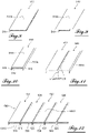
- FIG. 2 In picture 2 the result of a first process step applied to the first strip of flexible material 10 has been shown.
- the treatment applied consisted in folding, parallel to each of the two long sides of the rectangle constituting the strip, two parts thereof, to distinguish three parts therein: a central strip 11, slightly narrower than the first strip of flexible material 10 taken edge to edge, and a left flap 12 as well as a right flap 13, each now being delimited and connected to the central strip 11 by a hinge or fold formed in the flexible material.
- the flaps do not constitute only a small part of the first strip of flexible material 10. It is further specified that the material being flexible, the fold remains little marked at this stage.
- the surface of the right flap 13 constituted by a part of the decorative surface 10A has been identified. This part is called the outer surface of the right flap 13A.
- strip 22 itself provided with a left flap outer surface 22A.
- the outer surface of the right flap 13A and the outer surface of the left flap 22A are placed against each other over their entire length, the first and second strips of flexible material 10 and 20 being positioned parallel to each other. in the same plane.
- the contact between the two surfaces can be direct, or indirect with the interposition of a layer of an additional material if necessary.
- the outer surface of the right flap 13A and the outer surface of the left flap 22A are superimposed, their long sides being superimposed two by two and their short sides possibly also being superimposed, without this being essential for the proper performance of the method.
- the first and second strips of flexible material 10 and 20 not necessarily having the same length.
- a series of stitches 90 is then made over the entire common length of the left flap 12 and right flap 13, so as to immobilize or secure the first and second strips of flexible material 10 and 20.
- the stitches form a line, which is positioned very close to the fold which was not very marked, and it replaces the fold in the delimitation between the flap and the central band.
- the stitches of the series of stitches 90 can be individual stitches set in line with each other or stitches of an uninterrupted seam extending the full length of both flaps.
- FIG. 4 In figure 4 a subsequent step of the process has been shown, during which strips of flexible material 30 and 40 were also fixed after the first two strips of flexible material 10 and 20, on the side of the strip 20.
- the right flap 13 and the left flap of the second strip 22 have formed a double sewn flap 15.
- the right flap 23 and the left flap 32, having undergone another series of stitches 91 have formed a second sewn double flap 25.
- another double sewn flap 35 is made with the flaps 33 and 42 having undergone another series of stitches 92, and a double sewn flap 45 is formed with flaps 43 and 52 having undergone another series of stitches 93.
- a layer 100 (or pleated decoration) consisting of the assembly of strips of flexible material 10, 20, 30, 40 and other strips which can be put in place in the same way and attached by a series of stitches.
- the sheet 100 has on one of its faces a decorative surface 100A consisting of the assembly of the decorative surfaces of the central strips of each of the strips of flexible material 10, 20, 30, 40, etc.
- the sheet 100 On its opposite face, the sheet 100 has a surface from which the double sewn flaps 15, 25, 35, 45 etc. protrude.
- FIG. 5 In figure 5 we represent the sequence of operations.
- the web is the subject of a homogeneous sweeping or brushing in a single direction, so as to fold or lay down each of the double sewn flaps 15, 25, 35, 45 in a similar manner, with rotation of this flap along lines of stitches connecting the flaps of each of the strips of flexible material with its central strip.
- the web 100 (or pleated decoration) is found flattened, with the appearance of a pleated effect on the decorative surface 100A, each of the double sewn flaps 15, 25, 35, 45 being pressed against the fixing surface of the adjacent central strip, the orientation given to the movement being the same for each of the strips. Between two strips, the opening of a pleat is visible on the decorative face, but the pleat is held closed by the series of stitches along the length of the strips. On the opposite face, an attachment surface 100B is formed. It is regular and compatible with subsequent lamination, as the flaps are plated. They can even be glued against the rear face of the central bands, using a glue applied beforehand, as commented in relation to the figure 1 . It is possible to use the tablecloth as such, without proceeding to the steps which will be described in figures 6 and 7 , but these are also interesting.
- FIG. 6 In figure 6 the subsequent stage of the process has been shown, by which the ply 100 is bonded to a single piece of foam 200 to form a consolidated ply 300 (which will ultimately serve as a covering ply for the automobile part), this assembly step resembling a lamination.
- the piece of foam is a single flat piece, of modest thickness compared to the dimensions of the sheet 100, of which one dimension in its plane is of the same order of magnitude as the length of the strips, and the other dimension is of the same order. in magnitude as the sum of the widths of the central bands. It is a polyethylene or polyurethane foam.
- the single piece of foam 200 can also be glued on its face which comes into contact with the sheet 100, with a hot-melt glue, to allow assembly with the sheet 100.
- the hot-melt or heat-reactive glue present on one or the the other of the two assembled surfaces, namely the fixing face 100B and the surface of the single piece of foam 200, or on the two surfaces is activated by the application of heat, so as to join the two elements together.
- a three-dimensional textile can be used.
- the foam or the three-dimensional textile are lining materials (they thicken the ply) and also comfort materials: they offer a pleasant type of padding to the passenger.
- the consolidated ply 300 or covering ply is cut out as needed to define contours, rectilinear or curvilinear, in its plane, depending on its destination.
- FIG. 7 shows in section the result of the process: we have a single piece of foam 200 (or three-dimensional textile) on which is fixed a sheet 100 of pleated appearance showing on the face opposite the foam a pleasant decorative surface for the 'user. The stitches are invisible to the user, hidden under the folded soft material.
- the method is continued by the application of a deposit of hot-melt or heat-reactive glue by roller on the fixing face 300B of the consolidated ply, that is to say the foam face.
- a laminating press and a specific tool allowing to receive the format and the insert to be decorated.
- the tool is made up of two parts: a fixed lower female part shaped to receive the decoration and a male part shaped to receive the insert to be covered, and placed on a piston.
- the press is opened, then there is placement and positioning of the consolidated sheet 300 on the fixed plate, and placement of the insert to be decorated on the movable plate positioned in the upper part of the press.
- the glue is activated by applying infrared rays to the consolidated sheet 300, and the mobile platen is lowered for contacting and pressing. After cooling, the adhesion of the decoration to the insert is obtained, and the mobile plate is raised, then the insert bearing its covering is removed.
- the second embodiment which will now be presented, consists of making folds in an assembly of strips of flexible material (or decoration) on the back of which a foam or three-dimensional textile lining is present from the outset.
- FIG. 8 In figure 8 , the first step of this second embodiment of the invention has been shown.
- the strip of flexible material 510 comprises a decorative surface 510A and on its opposite face a complete covering of foam 518, immobilized and for example glued over its entire surface, in a uniform manner.
- the complete covering of foam 518 covers, in the variant presented, the whole of the face opposite the decorative surface 510A and is interrupted at its edges, for example because the strip of flexible material has been cut from a ply composed of an assembly of a layer of foam and a sheet of flexible material.
- the foam can be a polyurethane or polyethylene foam, and it can be replaced by a three-dimensional textile.
- the visible side of the lining (or fleece) material can already be glued.
- the complete covering of foam 518 (or textile) is the subject of cuts parallel to the long sides of the strip of flexible material 510 on each of the 2 long sides, and the thin lateral strips thus cut are detached, for example unstuck, from the flexible material.
- the width of foam removed is, on each side, greater than the thickness of the complete foam covering 518.
- the remaining foam is referenced as the central foam layer 519. It has a slightly narrower width than the strip of flexible material 510, taken edge to edge. It is also possible to provide that its thickness is not constant: it can for example be bevelled, ultimately creating an inclination between two pluses of the finished product.
- left flap 512 and right flap 513 are formed by folding the strip of flexible material, along the central layer of foam 519 (or textile), in s possibly pressing on the edge of the latter, and towards the face of the strip of flexible material in which the latter is located.
- the flaps are nevertheless not pressed against the band and remain free. The fold is not marked only moderately, due to the flexible nature of the material. Since the width of these flaps is defined by the width of foam that had been removed, the flaps, if held perpendicular to the web, each extend beyond the thickness of the central foam layer 518.
- FIG. 11 In figure 11 the subsequent step of the process has been shown by which a second strip of flexible material 520 identical or similar to the strip of flexible material 510, but free with respect to the strip 510, is brought closer to the latter by their respective flaps, and more precisely by the outer surface of right flap 513A and the outer surface of left flap 522A, which are placed face to face.
- a line of stitches 590 is carried out in a manner similar to what had been described in the first embodiment to secure the flaps, but it is carried out on the part of the flaps which exceeds the thickness of the central layer of foam or three-dimensional textile 519, just below the surface of this lining material.
- the second strip of flexible material comprises another central layer of foam 529 in the same way as the first strip, and that the stitches are placed in the same way vis-à-vis this other central layer of foam .
- FIG. 12 In figure 12 , a subsequent step of the process has been shown, during which strips of flexible material 530 and 540 similar to the first two strips were also fixed after the first two strips of flexible material 510 and 520, on the side of the strip 520.
- a sewn double flap 515 and other sewn double flaps 525, 535 and 545 are formed with the flaps and stitches.
- a temporary layer 600 consisting of the assembly of strips of flexible material 510, 520, 530, 540 and other strips.
- the temporary sheet 600 has on one of its faces a decorative surface 600A consisting of the assembly of the decorative surfaces. On its opposite face, the temporary sheet 600 has a temporary surface 600C from which protrude the double sewn flaps 515, 525, 535, 545 etc.
- FIG. 13 In figure 13 , there is shown the result of the sweeping, coating or plating of the flaps, in a single direction, against the temporary surface 600C, forming a final fixing surface 600D, and resulting in a ply 601 (final ply, or covering ply).
- the final 600D binding surface is smooth, stable and suitable for the lamination on a cabin part.
- the flaps surround and cover the most external part of the foam (or textile), under each of the bands, on a single side of each of the bands - in the figures, this is the most right side of each of the bands.
- the line of stitches constitutes the point of rotation, well defined and making the assembly firm and solid.
- the foam Conversely, on the left side, the foam remains uncovered, the flap being driven, by its seam, with the flap covering the foam of the neighboring band. This is how the double flaps 515, 525, ... are folded along the seam line.
- FIG. 14 The figure 14 shows in section the result of the process: we have an assembly of pieces of foam (or textile) 519, 529, etc. coated with the flexible material and sewn to each other by their respective long sides. The assembly bears the pleated appearance showing on the face opposite the foam a pleasant decorative surface for the user. If the thickness of the central layer of foam 519 is not constant, a relief or an inclination can be introduced into the decorative surface 600A.
- the process is continued by the application of a hot-melt or heat-reactive glue on the final fixing face 600D of the covering ply or final ply 601. Then one proceeds to the application of the pasted decoration on the cabin part or shape automobile - or insert - using the press and the specific tool mentioned above.
- the stitches can be replaced, for the purpose of securing the adjacent flaps, by staples, or even the use of glue, or even the use of clips, without calling into question the principles of the 'invention.
- the invention applies to motor vehicle door trims, as well as to dashboard panels.
Landscapes
- Engineering & Computer Science (AREA)
- Mechanical Engineering (AREA)
- Vehicle Interior And Exterior Ornaments, Soundproofing, And Insulation (AREA)
Applications Claiming Priority (1)
| Application Number | Priority Date | Filing Date | Title |
|---|---|---|---|
| FR2102416A FR3120566B1 (fr) | 2021-03-11 | 2021-03-11 | Procédé de fabrication d’une nappe de décoration pour habitacle de véhicule |
Publications (1)
| Publication Number | Publication Date |
|---|---|
| EP4056428A1 true EP4056428A1 (de) | 2022-09-14 |
Family
ID=75954015
Family Applications (1)
| Application Number | Title | Priority Date | Filing Date |
|---|---|---|---|
| EP22161457.1A Pending EP4056428A1 (de) | 2021-03-11 | 2022-03-10 | Verfahren zur herstellung einer dekormatte für den innenraum eines fahrzeugs |
Country Status (2)
| Country | Link |
|---|---|
| EP (1) | EP4056428A1 (de) |
| FR (1) | FR3120566B1 (de) |
Citations (4)
| Publication number | Priority date | Publication date | Assignee | Title |
|---|---|---|---|---|
| GB796614A (en) * | 1955-11-30 | 1958-06-18 | Standard Pressed Steel Co | Laminated trim pads suitable for use in vehicle bodies |
| US20130147228A1 (en) * | 2011-12-08 | 2013-06-13 | Faurecia Interior Systems, Inc. | Seam spacers for use with decorative stitching of vehicle interior components |
| EP3103678A1 (de) * | 2015-06-08 | 2016-12-14 | Cera TSC | Verkleidungsüberzug einer polsterung zum ausfüttern eines sitzelements eines kraftfahrzeugs |
| FR3086225A1 (fr) * | 2018-09-24 | 2020-03-27 | Psa Automobiles Sa | Procede de realisation d’une housse d’habillage de siege, a reliefs longitudinaux |
-
2021
- 2021-03-11 FR FR2102416A patent/FR3120566B1/fr active Active
-
2022
- 2022-03-10 EP EP22161457.1A patent/EP4056428A1/de active Pending
Patent Citations (4)
| Publication number | Priority date | Publication date | Assignee | Title |
|---|---|---|---|---|
| GB796614A (en) * | 1955-11-30 | 1958-06-18 | Standard Pressed Steel Co | Laminated trim pads suitable for use in vehicle bodies |
| US20130147228A1 (en) * | 2011-12-08 | 2013-06-13 | Faurecia Interior Systems, Inc. | Seam spacers for use with decorative stitching of vehicle interior components |
| EP3103678A1 (de) * | 2015-06-08 | 2016-12-14 | Cera TSC | Verkleidungsüberzug einer polsterung zum ausfüttern eines sitzelements eines kraftfahrzeugs |
| FR3086225A1 (fr) * | 2018-09-24 | 2020-03-27 | Psa Automobiles Sa | Procede de realisation d’une housse d’habillage de siege, a reliefs longitudinaux |
Also Published As
| Publication number | Publication date |
|---|---|
| FR3120566B1 (fr) | 2023-12-01 |
| FR3120566A1 (fr) | 2022-09-16 |
Similar Documents
| Publication | Publication Date | Title |
|---|---|---|
| AU751796B2 (en) | Vehicle trim component having two-part cover material and method and apparatus for producing same | |
| EP0895894B1 (de) | Ein Autoteil mit einer geflockten Auskleidung und Verfahren zum Flocken eines solchen Teiles | |
| WO2015015131A1 (fr) | Procede de formage de garniture pour siege automobile | |
| FR2975649A1 (fr) | Piece de panneau interieur avec couverture d'airbag | |
| FR2608964A1 (fr) | Panneaux composites moules | |
| WO2017140982A1 (fr) | Coque de bagage, bagage comprenant une telle coque de bagage, et procédé de fabrication de la coque de bagage | |
| FR3009222A1 (fr) | Formage d'une garniture pour siege automobile | |
| EP1841584B1 (de) | Verfahren zur herstellung eines mehrschichtigen teils mit flexiblem lokalem bereich, z.b. zur verwendung als innenausstattung für ein kraftfahrzeug | |
| EP4056428A1 (de) | Verfahren zur herstellung einer dekormatte für den innenraum eines fahrzeugs | |
| FR2900607A1 (fr) | Siege de vehicule automobile comportant une coiffe de garnissage amovible, et coiffe pour un tel siege | |
| EP3423600B1 (de) | Verfahren zur herstellung einer dekorativen auskleidung für ein kraftfahrzeuginnenraumelement und einheit mit einem auskleidungelement | |
| EP3481673B1 (de) | Abdecksystem für den schaltknüppel eines kraftfahrzeugs | |
| FR2744947A1 (fr) | Procede d'habillage, par une feuille, d'une piece injectee, moule pour la mise en oeuvre du procede et piece obtenue | |
| FR3074458A1 (fr) | Panneau d'equipement interieur de vehicule automobile et procede de fabrication associe | |
| EP3774444B1 (de) | Dekorschicht für ein kraftfahrzeugbauteil | |
| WO2020030765A1 (fr) | Procédé pour réaliser un bagage, en particulier un sac de voyage souple ou semi-rigide | |
| EP1798112A2 (de) | Verfahren zum Spritzgiessen eines Ausstattungsteiles sowie danach hergestelltes Ausstattungsteil | |
| FR3134957A1 (fr) | Revêtement matelassé pour intérieur de véhicule | |
| EP0094406A1 (de) | Bausatz und verfahren zur herstellung eines lampenschirmes mit persönlicher note | |
| FR2757103A1 (fr) | Procede pour realiser une piece finie composite comportant un revetement recouvrant une face d'une couche de mousse en matiere plastique et piece finie | |
| FR2817503A1 (fr) | Procede pour la realisation d'un panneau tel qu'une tablette arriere de vehicule automobile | |
| FR3121866A1 (fr) | Procédé de fabrication d’une pièce d’habillage intérieur de véhicule et pièce obtenue | |
| EP4101700A1 (de) | Verfahren zur verkleidung eines fahrzeuginnenraumteils eines kraftfahrzeugs | |
| EP0664403A1 (de) | Vorrichtung zum Aufbringen einer Bekleidung auf einen Träger durch Verfalzung und ihre Anwendung in Kraftfahrzeugen | |
| FR2489745A1 (fr) | Ecran pour pare-soleil de vehicules, obtenu par thermocompression et procede de fabrication d'un tel pare-soleil |
Legal Events
| Date | Code | Title | Description |
|---|---|---|---|
| PUAI | Public reference made under article 153(3) epc to a published international application that has entered the european phase |
Free format text: ORIGINAL CODE: 0009012 |
|
| STAA | Information on the status of an ep patent application or granted ep patent |
Free format text: STATUS: THE APPLICATION HAS BEEN PUBLISHED |
|
| AK | Designated contracting states |
Kind code of ref document: A1 Designated state(s): AL AT BE BG CH CY CZ DE DK EE ES FI FR GB GR HR HU IE IS IT LI LT LU LV MC MK MT NL NO PL PT RO RS SE SI SK SM TR |
|
| STAA | Information on the status of an ep patent application or granted ep patent |
Free format text: STATUS: REQUEST FOR EXAMINATION WAS MADE |
|
| 17P | Request for examination filed |
Effective date: 20221121 |
|
| RBV | Designated contracting states (corrected) |
Designated state(s): AL AT BE BG CH CY CZ DE DK EE ES FI FR GB GR HR HU IE IS IT LI LT LU LV MC MK MT NL NO PL PT RO RS SE SI SK SM TR |
|
| P01 | Opt-out of the competence of the unified patent court (upc) registered |
Effective date: 20230517 |
|
| GRAP | Despatch of communication of intention to grant a patent |
Free format text: ORIGINAL CODE: EPIDOSNIGR1 |
|
| STAA | Information on the status of an ep patent application or granted ep patent |
Free format text: STATUS: GRANT OF PATENT IS INTENDED |