EP4056397B1 - Antriebsbaugruppe für ein fahrzeug - Google Patents
Antriebsbaugruppe für ein fahrzeug Download PDFInfo
- Publication number
- EP4056397B1 EP4056397B1 EP22159626.5A EP22159626A EP4056397B1 EP 4056397 B1 EP4056397 B1 EP 4056397B1 EP 22159626 A EP22159626 A EP 22159626A EP 4056397 B1 EP4056397 B1 EP 4056397B1
- Authority
- EP
- European Patent Office
- Prior art keywords
- housing
- subregion
- brake
- drive module
- wheel shaft
- Prior art date
- Legal status (The legal status is an assumption and is not a legal conclusion. Google has not performed a legal analysis and makes no representation as to the accuracy of the status listed.)
- Active
Links
Images


Classifications
-
- B—PERFORMING OPERATIONS; TRANSPORTING
- B60—VEHICLES IN GENERAL
- B60K—ARRANGEMENT OR MOUNTING OF PROPULSION UNITS OR OF TRANSMISSIONS IN VEHICLES; ARRANGEMENT OR MOUNTING OF PLURAL DIVERSE PRIME-MOVERS IN VEHICLES; AUXILIARY DRIVES FOR VEHICLES; INSTRUMENTATION OR DASHBOARDS FOR VEHICLES; ARRANGEMENTS IN CONNECTION WITH COOLING, AIR INTAKE, GAS EXHAUST OR FUEL SUPPLY OF PROPULSION UNITS IN VEHICLES
- B60K7/00—Disposition of motor in, or adjacent to, traction wheel
- B60K7/0007—Disposition of motor in, or adjacent to, traction wheel the motor being electric
-
- B—PERFORMING OPERATIONS; TRANSPORTING
- B60—VEHICLES IN GENERAL
- B60K—ARRANGEMENT OR MOUNTING OF PROPULSION UNITS OR OF TRANSMISSIONS IN VEHICLES; ARRANGEMENT OR MOUNTING OF PLURAL DIVERSE PRIME-MOVERS IN VEHICLES; AUXILIARY DRIVES FOR VEHICLES; INSTRUMENTATION OR DASHBOARDS FOR VEHICLES; ARRANGEMENTS IN CONNECTION WITH COOLING, AIR INTAKE, GAS EXHAUST OR FUEL SUPPLY OF PROPULSION UNITS IN VEHICLES
- B60K17/00—Arrangement or mounting of transmissions in vehicles
- B60K17/04—Arrangement or mounting of transmissions in vehicles characterised by arrangement, location or kind of gearing
- B60K17/14—Arrangement or mounting of transmissions in vehicles characterised by arrangement, location or kind of gearing the motor of fluid or electric gearing being disposed in, or adjacent to, traction wheel
- B60K17/145—Arrangement or mounting of transmissions in vehicles characterised by arrangement, location or kind of gearing the motor of fluid or electric gearing being disposed in, or adjacent to, traction wheel the electric gearing being disposed in or adjacent to traction wheel
Definitions
- the present invention relates to a drive assembly for a vehicle, in particular for a road vehicle such as a car, a truck or a bus.
- Fully or partially electrically driven vehicles have a drive device with an electric motor, which is kinematically coupled to at least one axle or to at least one wheel of the vehicle in order to drive it.
- a gear is provided to establish a kinematic connection between the wheel and the electric motor.
- An electrical energy storage device for example an accumulator, can be provided as an electrical energy source for the motor, with the electric motor being electrically connected to the energy storage device via power electronics.
- a drive assembly in which an electrical machine, a gearbox and power electronics are housed in a common housing. Furthermore, a friction brake system, which brakes a drive axle connected to the transmission, is housed in a partial space that is encapsulated from the rest of the housing in order to prevent fine dust from penetrating into the rest of the housing and fine dust from escaping to the outside.
- a drive assembly according to the invention for a vehicle comprises a housing, an electrical machine accommodated in a first portion of the housing and a transmission accommodated in a second portion of the housing, which is kinematically coupled to the electrical machine, the second portion of the housing forming a lubricating fluid reservoir, into which the gearbox protrudes.
- the drive assembly comprises a wheel shaft that is kinematically coupled to the transmission for connection to a wheel of the vehicle, which protrudes in the second portion of the housing and from the second portion of the housing onto an outside of the housing, and a friction brake system with a braking device, which has a has a brake body attached to the wheel shaft and a brake actuator for exerting a frictional force on the brake body.
- the brake body is arranged in the second portion of the housing and projects into the lubricant reservoir.
- One idea underlying the invention is to provide a highly integrated drive assembly in which an electric machine, a transmission and a brake system are combined into one assembly, the brake system comprising a friction brake which is either arranged on the outside of the housing or within a housing in this way is arranged so that it runs in an oil bath or lubricant reservoir of the housing.
- the friction brake comprises a brake body, such as a brake disc or a brake drum, which is connected in a rotationally fixed manner to a wheel shaft coupled to the electric machine via the transmission.
- the case defines you Interior in which the electrical machine, for example a three-phase machine such as a synchronous or asynchronous machine, is accommodated in a first sub-area and the transmission is accommodated in a second sub-area.
- the first and second subregions are sealed against each other in a fluid-tight manner.
- the brake body protrudes into the lubricant reservoir, this offers the advantage that the brake body is cooled very efficiently. At the same time, fine dust particles are bound in the lubricating fluid. In particular, the maintenance effort of the braking device can be significantly reduced in this way. Furthermore, the brake system can be easily installed together with the wheel shaft. In particular, no portion of the housing has to be provided exclusively for the braking device, but rather this can be integrated into the portion provided for the transmission.
- the friction brake system has a hydraulic switching unit that is hydraulically connected to the braking device and is set up to vary the frictional force exerted by the brake actuator, the switching unit being accommodated in the housing, in particular in the second portion of the housing.
- the switching unit can, for example, have one or more valves, for example to drain or supply brake fluid to the brake actuator.
- a first wheel shaft and a second wheel shaft are kinematically coupled to the transmission, wherein the friction brake system has a first braking device with a first brake body attached to the first wheel shaft and a first brake actuator for exerting a frictional force on the first brake body, and a second braking device with a second brake body attached to the second wheel shaft and a second brake actuator for exerting a frictional force has the second brake body, and wherein the switching unit is connected to the first and second braking devices and is set up to vary the frictional force exerted by the brake actuators on an individual shaft basis.
- the switching unit can, for example, be set up to carry out an anti-lock function.
- a pressure generating device for example in the form of a pump, can also be integrated into the switching unit.
- the drive assembly has a steering system accommodated in a third portion of the housing.
- the third subregion is preferably designed to be fluid-tight to the first and/or the second subregion.
- the steering system can, for example, have an electric steering drive or servo motor, a steering gear connected to the steering drive motor and handlebars coupled to the steering gear, which protrude from the third portion onto the outside of the housing. This further increases the degree of integration of the drive assembly.
- the drive assembly has an electronic control device accommodated in a fourth portion of the housing, which is electrically connected to the electric machine and the friction brake system and is set up to control operation of the electric machine and the friction brake system.
- the control device can in particular have a power electronic circuit, such as an inverter circuit, and a signal electronic circuit.
- the signal electronic circuit can, for example, have one or more processors, for example in the form of a CPU, an FPGA or an ASIC, and one or more memory components, for example in the form of non-volatile memories such as flash memories or hard drives.
- the signal electronic circuit is set up to generate brake actuation signals in order to actuate the braking device, for example in order to generate a brake pressure for applying the frictional force to the brake piece by the brake actuator and/or to actuate the switching unit, for example in order to carry out an anti-locking function.
- the signal electronic circuit is set up to control the power electronic circuit, for example to operate the electrical machine as a motor or as a generator.
- a common control unit is thus provided for the brake system, the electric machine and, optionally, for operating the steering device.
- This control device is housed in a fluid-tight fourth portion of the housing, which can be located, for example, adjacent to the first portion.
- walls of the housing defining the first subregion and the second subregion are formed in one piece. Furthermore, it can be provided that walls of the housing defining the first subregion, the second subregion and the third subregion are formed in one piece. Further optionally, it can be provided that walls of the housing defining the first subregion, the second subregion and the fourth subregion are formed in one piece. In addition, it is also conceivable that the walls of the housing defining the first subregion, the second subregion, the third subregion and the fourth subregion are formed in one piece.
- the various subregions can be integrated as cavities in a monolithic housing. For example, it is conceivable to design the housing as a cast part. The one-piece design of the housing offers the advantage that it can be produced cost-effectively and the assembly effort is reduced.
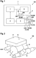
- Fig. 1 shows a schematic block diagram of a drive assembly 100 for a vehicle.
- the drive assembly 100 includes a housing 1, an electric machine 2, a transmission 3, a wheel shaft 4 and a friction brake system 5.
- a steering system 6 and/or a control device 7 can optionally be provided.
- the drive assembly 100 described below can be used in particular to drive a road vehicle, such as a car, a truck or a bus.
- Fig. 1 is shown schematically, the electric machine 2, the transmission 3 and the friction brake system 5 are accommodated in the housing 1.
- the control device 7 and the steering system 6 are optionally also accommodated in the housing 1.
- the transmission 3 is kinematically coupled to the electrical machine 2.
- the first and second wheel shafts 4A, 4B are in turn kinematically coupled to the transmission 3.
- the electrical machine 2 can in particular be a three-phase machine, for example a synchronous machine or an asynchronous machine.
- the friction brake system 5 has a braking device 50.
- a first braking device 50A can be provided for braking the first wheel shaft 50A and a second braking device 50B for braking the second wheel shaft 50B, as shown in FIG Fig. 1 is shown as an example.
- the friction brake system 5 can also have a hydraulic switching unit 55.
- each switching unit 50 can each have a brake body 51 and a brake actuator 52.
- the brake body 51 can be, for example, a brake disc or a brake drum and is connected to the wheel shaft 50 in a rotationally fixed manner.
- the brake actuator 52 which can be a hydraulically actuated brake cylinder, for example, has a friction body (not shown) which can be applied to the brake body 51 in order to generate a frictional force.
- the brake actuator 52 can be actuated, for example, via a manually operable master brake cylinder (not shown) and/or a pressure generating device (not shown), such as a plunger.
- a manually operable master brake cylinder not shown
- a pressure generating device not shown
- the first braking device 50A has a first brake body 51A attached to the first wheel shaft 4A and a first brake actuator 52A for exerting a frictional force on the first brake body 51A.
- the second braking device 50B includes a second brake body 51B attached to the second wheel shaft 4B and a second brake actuator 52B for exerting a frictional force on the second brake body 51B.
- the switching unit 55 is in Fig. 1 shown only symbolically and is hydraulically connected to the first and second braking devices 50A, 50B.
- the switching unit 55 can in particular have different valves 55A, 55B, which selectively connect or separate the respective brake actuator 52A, 52B from a pressure source for brake fluid, in particular in order to individually adjust a frictional force on each wheel shaft 4A, 4B to be able to, for example to carry out an anti-locking function.
- the switching unit 55 is thus set up to vary the frictional force exerted by the brake actuator 52.
- the optional control device 7 can, for example, have a power electronic circuit (not shown) and a signal or control electronic circuit (not shown).
- the control device 7, in particular the power electronic circuit is electrically connected to the electrical machine.
- the power electronic circuit can have an inverter circuit.
- the signal electronic circuit can, for example, have one or more processor units, for example CPUs, FPGAs, ASICs or the like, and one or more data memories, for example SD memory, HD memory or the like.
- the signal-electronic circuit is signal-connected to the power-electronic circuit and is set up to control it in order to operate the electrical machine 2, for example as a motor or as a generator.
- the control device 7, in particular the signal-electronic circuit is also signal-connected to the switching unit 55 in order to control it, for example to switch the valves 55A, 55B.
- the optional steering device 6 can, for example, be a steering drive (in Fig. 1 not shown), for example in the form of an electric motor, a steering gear connected to the steering drive (in Fig. 1 not shown) and handlebars or actuators (in Fig. 1 not shown) which are kinematically coupled to the steering gear.
- the steering device 6 can, as in Fig. 1 shown as an example, be signal-connected to the control device 7, in particular the signal-electronic circuit, the control device 7 being set up to actuate the steering device 6, for example by generating a control signal which causes an actuation of the steering drive.
- Fig. 2 shows schematically and purely by way of example an external view of the housing 1 of the drive assembly 100.
- the housing 1 has several partial areas 11, 12, 13, 14.
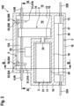
- Fig. 3 shows schematically a sectional view of the drive assembly 100.
- Fig. 4 shows a sectional view of the in Fig. 3 shown drive assembly 100, which is when cut along the in Fig. 3 drawn line AA results.
- Fig. 5 shows a sectional view of the in Fig. 3 Drive assembly shown, which is when cut along the in Fig. 3 drawn line BB results.
- the housing 1 has a defined interior 10.
- the interior 10 is delimited by walls 16 and divided into at least a first portion 11 and a second portion 12.
- Fig. 3 to 5 is shown purely by way of example that the interior 10 is additionally divided into a third sub-area 13 and a fourth sub-area 14.
- the walls 16, which define the partial areas 11, 12, 13, 14, can in particular be designed or manufactured in one piece, for example in a casting process. However, it is also conceivable that only a part of the walls 16 is formed in one piece, and one or more of the partial areas 11, 12, 13, 14 are defined by separate walls that are fastened to the one-piece walls 16, for example flanged to them.
- the electric machine 2 is in Fig. 3 shown only schematically and generally has a stator 20 and a rotor 21 which can be rotated by the stator 20 about a rotor axis of rotation and which can be arranged, for example, within the stator 20, as in Fig. 3 shown as an example.
- the electrical machine 2 can be arranged in the first subregion 11.
- the first portion 11 can in particular be a cylindrical cavity which encloses a longitudinal axis, as is particularly the case in FIG Fig. 3 and 5 is recognizable.
- a rotor shaft 22 that is firmly connected to the rotor 21 can protrude into the second portion 12 of the housing 1 through a recess in a wall 16 delimiting the first portion 11.
- the first and second portions 11, 12 are sealed in a fluid-tight manner relative to one another, for example by means of sealing rings (not shown) or the like.
- the gearbox 3 is in Fig. 3 shown only symbolically as a block and can in particular have several transmission members, such as gears, which mesh with one another in order to convert a first torque present on the rotor shaft 22 at a first speed into a second torque at a second To convert the speed on the wheel shaft 4 or the wheel shafts 4A, 4B.
- the transmission 3 is accommodated in the second portion 12 of the housing 1 and is kinematically coupled to the electric machine 2, in particular to the rotor shaft 22.
- the second subregion 12 can adjoin the first subregion 12 in particular in a direction along the longitudinal axis of the first subregion 12 and can further extend laterally of the first subregion 12.
- Fig. 3 shown only symbolically as a block and can in particular have several transmission members, such as gears, which mesh with one another in order to convert a first torque present on the rotor shaft 22 at a first speed into a second torque at a second To convert the speed on the wheel shaft 4 or the wheel shafts 4A, 4B.
- the second portion 12 forms a lubricating fluid reservoir 12A, i.e. a trough in which lubricating fluid such as oil can be accommodated or received.
- a level FL of the lubricating fluid is shown as a dashed line.
- the transmission 3 is arranged in the second portion 12 in such a way that it protrudes into the lubricating fluid reservoir 12A or into the lubricating fluid, as shown in FIG Fig. 4 is shown schematically.
- the ones in the Fig. 3 to 5 Drive assembly 100 shown as an example has, as described above with reference to Fig. 1 described, a first and a second wheel shaft 4A, 4B.
- the wheel shafts 4A, 4B can extend in particular parallel to the rotor shaft 21.
- the wheel shafts 4A, 4B extend within the second portion 12 of the housing 1 and each protrude from the second portion 12 onto an outside 15 of the housing 1.
- the wheel shafts 4A, 4B can each extend through a recess in an end wall 16 of the housing 1, as shown in FIG Fig. 4 is shown schematically.
- the wheel shafts 4A, 4B are each kinematically coupled to the transmission 3, as has already been explained above and in the Fig. 3 and 4 is shown schematically.
- the first and second braking devices 50A, 50B of the friction brake system 5 are each arranged in the second portion 12 of the housing 1.
- the first brake body 51A of the first braking device 50A and the second brake body 51B of the second braking device 50B can each be implemented as brake disks, which are connected in a rotationally fixed manner to the respective wheel shaft 4A, 4B.
- other designs are also conceivable, for example in the form of brake drums.
- the first brake actuator 52A of the first brake device 50A and the second brake actuator 52B of the second Braking device 50B can, for example, be implemented as a hydraulic brake cylinder, as described above, and in particular be attached to a wall 16 of the housing 1, as shown in FIG Fig. 3 and 4 shown schematically.
- the wheel shafts 4A, 4B and the brake bodies 51A, 51B attached thereto are arranged in the second portion 12 of the housing 1 in such a way that the brake bodies 51A, 51B protrude into the lubricating fluid reservoir 12A or into the lubricating fluid 12A.
- the brake bodies 51A, 51B are cooled very well by the lubricating fluid 12A and abrasion resulting from the friction between the brake bodies 51A, 51B and the friction piece of the brake actuator 52A, 52B is bound in the lubricating fluid.
- the lubricating liquid can be circulated through a filter device (not shown) by means of a conveying device (not shown) such as a pump in order to separate particles from the lubricating liquid.
- the optional hydraulic switching unit 55 is in Fig. 3 shown only symbolically as a block and can be arranged, for example, in the second portion 12 of the housing 1. However, it would also be conceivable to accommodate the switching unit 55 in another of the subareas 11, 13, 14.
- the steering system 6 is optionally accommodated in the third section 13, as shown in Fig. 3 is shown schematically.
- the third portion 13 can, for example, be a substantially cylindrical cavity which extends parallel to the first portion 11, as in Fig. 3 shown as an example and schematically.
- the third sub-area 13 can in particular be completely spatially separated from the first and second sub-areas 11, 12, as shown in Fig. 3 is shown schematically.
- the steering system 6 is in Fig. 3 also shown only schematically, with the steering drive 30 and the steering gear 31 being shown as a block.
- the handlebars 32A, 32B can protrude from the third portion 13 onto the outside 15 of the housing 1, as in Fig. 3 shown schematically.
- the optional control device 7 is symbolically represented as a block in Fig. 5 shown and can be constructed in the manner described above. As in Fig. 4 can be seen, the control device 7 is in the fourth sub-area 14 of the housing 1 arranged.
- the fourth subregion 14 can, for example, be arranged adjacent to the first subregion 11 with respect to a radial direction which extends perpendicular to the longitudinal axis of the first subregion 11, as shown in FIG Fig. 4 is shown as an example.
- the fourth subregion 14 can be delimited by a substantially flat floor and several side walls extending from it, as shown in FIG Fig. 5 is shown schematically.
- the fourth subregion 14 is preferably sealed in a fluid-tight manner relative to the first subregion 11 and/or the second subregion 12 and/or the third subregion 13.
- the fourth portion 14 can be closed by a cover 17.
- FIG. 6 Another drive assembly 100 is shown as an example.
- Drive assembly 100 shown differs from that in the Fig. 3 to 5 illustrated drive assembly 100 only in that the first and second braking devices 50A, 50B are arranged on the outside 15, that is, outside the interior 10 of the housing 1.
- the brake bodies 51A, 51B are arranged on the outside 15 of the housing 1 and are therefore accessible from the outside and cooled by ambient air.
- the brake actuators 52A, 52B can, for example, be attached to an outer surface 1a of the housing 1, as shown in FIG Fig. 6 is shown schematically.
Landscapes
- Engineering & Computer Science (AREA)
- Chemical & Material Sciences (AREA)
- Combustion & Propulsion (AREA)
- Transportation (AREA)
- Mechanical Engineering (AREA)
- Arrangement Or Mounting Of Propulsion Units For Vehicles (AREA)
Description
- Die vorliegende Erfindung betrifft eine Antriebsbaugruppe für ein Fahrzeug, insbesondere für ein Straßenfahrzeug wie einen PKW, einen LKW oder einen Bus.
- Ganz oder teilweise elektrisch angetriebene Fahrzeuge weisen eine Antriebsvorrichtung mit einem Elektromotor auf, welcher kinematisch an zumindest eine Achse oder an zumindest ein Rad des Fahrzeugs gekoppelt ist, um diese bzw. dieses anzutreiben. Typischerweise ist ein Getriebe vorgesehen, um eine kinematische Verbindung zwischen Rad und Elektromotor herzustellen. Als elektrische Energiequelle für den Motor kann ein elektrischer Energiespeicher, z.B. ein Akkumulator, vorgesehen sein, wobei der Elektromotor über eine Leistungselektronik mit dem Energiespeicher elektrisch verbunden ist.
- In der
WO 2018/150007 A1 wird eine Antriebsbaugruppe beschrieben, bei welcher eine elektrische Maschine, ein Getriebe und eine Leistungselektronik in einem gemeinsamen Gehäuse untergebracht sind. Ferner ist eine Reibbremsanlage, welche eine mit dem Getriebe verbundene Antriebsachse bremst, in einem vom Rest des Gehäuses abgekapselten Teilraum untergebracht, um das Eindringen von Feinstaub in das übrige Gehäuse und ein Austreten von Feinstaub nach außen hin zu verhindern. - Weitere Antriebsbaugruppen werden in der
DE 10 2011 113 198 A1 und derDE 10 2010 017 991 A1 offenbart.US 2009/025991 A1 offenbart eine Antriebsbaugruppe mit den Merkmalen des Oberbegriffs des Anspruchs 1. - Erfindungsgemäß ist eine Antriebsbaugruppe mit den Merkmalen des Anspruchs 1 vorgesehen.
- Eine erfindungsgemäße Antriebsbaugruppe für ein Fahrzeug umfasst ein Gehäuse, eine in einem ersten Teilbereich des Gehäuses aufgenommene elektrische Maschine und ein in einem zweiten Teilbereich des Gehäuses aufgenommenes Getriebe, welches kinematisch an die elektrische Maschine gekoppelt ist, wobei der zweite Teilbereich des Gehäuses ein Schmierflüssigkeitsreservoir ausbildet, in welches das Getriebe hineinragt. Ferner umfasst die Antriebsbaugruppe eine kinematisch an das Getriebe gekoppelte Radwelle zur Verbindung mit einem Rad des Fahrzeugs, welche sich in dem zweiten Teilbereich des Gehäuses und aus dem zweiten Teilbereich des Gehäuses auf eine Außenseite des Gehäuses herausragt, und eine Reibbremsanlage mit einer Bremseinrichtung, welche einen an der Radwelle befestigten Bremskörper und einen Bremsaktuator zum Ausüben einer Reibkraft auf den Bremskörper aufweist. Der Bremskörper ist in dem zweiten Teilbereich des Gehäuses angeordnet und ragt in das Schmierflüssigkeitsreservoir hinein.
- Eine der Erfindung zugrundeliegende Idee besteht darin, eine hochintegrierte Antriebsbaugruppe bereitzustellen, bei der eine elektrische Maschine, ein Getriebe und eine Bremsanlage zu einer Baugruppe zusammengefasst sind, wobei die Bremsanlage eine Reibbremse umfasst, welche entweder außen an dem Gehäuse angeordnet ist oder innerhalb eines Gehäuses derart angeordnet ist, dass sie in einem Ölbad bzw. Schmiermittelreservoir des Gehäuses läuft. Die Reibbremse umfasst einen Bremskörper, wie z.B. eine Bremsscheibe oder eine Bremstrommel, der drehfest mit einer über das Getriebe an die elektrische Maschine gekoppelte Radwelle verbunden ist. Das Gehäuse definiert einen Innenraum, in dem die elektrische Maschine, z.B. eine Drehstrommaschine wie eine Synchron- oder eine Asynchronmaschine, in einem ersten Teilbereich und das Getriebe in einem zweiten Teilbereich aufgenommen ist. Der erste und der zweite Teilbereich sind gegeneinander fluiddicht abgedichtet.
- Wenn der Bremskörper in das Schmierflüssigkeitsreservoir hineinragt, bietet dies den Vorteil, dass der Bremskörper sehr effizient gekühlt wird. Gleichzeitig werden Feinstaubpartikel in der Schmierflüssigkeit gebunden. Insbesondere kann auf diese Weise der Wartungsaufwand der Bremseinrichtung deutlich reduziert werden. Weiterhin kann die Bremsanlage einfach zusammen mit der Radwelle montiert werden. Insbesondere muss kein Teilbereich des Gehäuses ausschließlich für die Bremseinrichtung vorgesehen werden, sondern diese kann in den für das Getriebe vorgesehenen Teilbereich integriert.
- Vorteilhafte Ausgestaltungen und Weiterbildungen ergeben sich aus den weiteren Unteransprüchen sowie aus der Beschreibung unter Bezugnahme auf die Figuren der Zeichnung.
- Gemäß manchen Ausführungsformen kann vorgesehen sein, dass die Reibbremsanlage eine hydraulisch mit der Bremseinrichtung verbundene hydraulische Schalteinheit aufweist, welche dazu eingerichtet ist, die vom Bremsaktuator ausgeübte Reibkraft zu variieren, wobei die Schalteinheit in dem Gehäuse aufgenommen ist, insbesondere im zweiten Teilbereich des Gehäuses. Die Schalteinheit kann z.B. ein oder mehrere Ventile aufweisen, z.B. um Bremsflüssigkeit aus dem Bremsaktuator abzulassen oder diesem zuzuführen. Durch die Anordnung der Schalteinheit innerhalb des Gehäuses wird ein kompakter Aufbau erzielt und der Integrationsgrad der Antriebsbaugruppe weiter erhöht.
- Gemäß manchen Ausführungsformen kann vorgesehen sein, dass eine erste Radwelle und eine zweite Radwelle kinematisch an das Getriebe gekoppelt sind, wobei die Reibbremsanlage eine erste Bremseinrichtung mit einem an der ersten Radwelle befestigten ersten Bremskörper und einem ersten Bremsaktuator zum Ausüben einer Reibkraft auf den ersten Bremskörper, und eine zweite Bremseinrichtung mit einem an der zweiten Radwelle befestigten zweiten Bremskörper und einen zweiten Bremsaktuator zum Ausüben einer Reibkraft auf den zweiten Bremskörper aufweist, und wobei die Schalteinheit mit der ersten und der zweiten Bremseinrichtung verbunden und dazu eingerichtet ist, die von den Bremsaktuatoren ausgeübte Reibkraft wellenindividuell zu variieren. Die Schalteinheit kann beispielsweise dazu eingerichtet sein, eine Antiblockierfunktion auszuführen. Optional kann in die Schalteinheit ferner eine Druckerzeugungseinrichtung, z.B. in Form einer Pumpe integriert sein.
- Gemäß manchen Ausführungsformen kann vorgesehen sein, dass die Antriebsbaugruppe eine in einem dritten Teilbereich des Gehäuses aufgenommene Lenkanlage aufweist. Der dritte Teilbereich ist vorzugsweise fluiddicht zu dem ersten und/oder dem zweiten Teilbereich ausgeführt. Die Lenkanlage kann z.B. einen elektrischen Lenkantriebs- oder Servomotor, ein mit dem Lenkantriebsmotor verbundenes Lenkgetriebe und an das Lenkgetriebe gekoppelte Lenkstangen aufweisen, welche aus dem dritten Teilbereich auf die Außenseite des Gehäuses herausragen. Somit wird der Integrationsgrad der Antriebsbaugruppe weiter vergrößert.
- Gemäß manchen Ausführungsformen kann vorgesehen sein, dass die Antriebsbaugruppe eine in einem vierten Teilbereich des Gehäuses aufgenommene elektronische Steuerungsvorrichtung aufweist, welche elektrisch leitend mit der elektrischen Maschine und der Reibbremsanlage verbunden und dazu eingerichtet ist, einen Betrieb der elektrischen Maschine und der Reibbremsanlage zu steuern. Die Steuerungsvorrichtung kann insbesondere eine leistungselektronische Schaltung, wie z.B. eine Inverterschaltung, und eine signalelektronische Schaltung aufweisen. Die signalelektronische Schaltung kann beispielsweise einen oder mehrere Prozessoren, z.B. in Form einer CPU, eines FPGA oder eines ASIC, sowie einen oder mehrere Speicherbausteine, z.B. in Form von nicht-flüchtigen Speichern wie Flash-Speichern oder Festplatten aufweisen. Die signalelektronische Schaltung ist einerseits dazu eingerichtet, Bremsaktuationssignale zu erzeugen, um die Bremseinrichtung zu betätigen, z.B. um einen Bremsdruck zur Aufbringung der Reibkraft durch den Bremsaktuator auf das Bremsstück zu erzeugen und/oder die Schalteinheit zu betätigen, z.B. um eine Antiblockierfunktion auszuführen. Ferner ist die signalelektronische Schaltung dazu eingerichtet, die leistungselektronische Schaltung anzusteuern, z.B. um die elektrische Maschine als Motor oder als Generator zu betreiben. Somit wird ein gemeinsames Steuergerät für die Bremsanlage, die elektrische Maschine sowie optional zum Betreiben die Lenkeinrichtung bereitgestellt. Diese Steuerungsvorrichtung ist in einem fluiddichten vierten Teilbereich des Gehäuses untergebracht, der z.B. benachbart zu dem ersten Teilbereich gelegen sein kann.
- Gemäß manchen Ausführungsformen kann vorgesehen sein, dass den ersten Teilbereich und den zweiten Teilbereich definierende Wandungen des Gehäuses einstückig ausgebildet sind. Weiterhin kann vorgesehen sein, dass den ersten Teilbereich, den zweiten Teilbereich und den dritten Teilbereich definierende Wandungen des Gehäuses einstückig ausgebildet sind. Weiter optional kann vorgesehen sein, dass den ersten Teilbereich, den zweiten Teilbereich und den vierten Teilbereich definierende Wandungen des Gehäuses einstückig ausgebildet sind. Darüber hinaus ist auch denkbar, dass die den ersten Teilbereich, den zweiten Teilbereich, den dritten Teilbereich und den vierten Teilbereich definierende Wandungen des Gehäuses einstückig ausgebildet sind. Allgemein können die verschiedenen Teilbereiche als Hohlräume in einem monolithischen Gehäuse integriert sein. Beispielsweise ist es denkbar, das Gehäuse als Gussteil auszuführen. Die einstückige Ausführung des Gehäuses bietet den Vorteil, dass dieses kostengünstig herstellbar ist und der Montageaufwand verringert wird.
- Im Folgenden wird die Erfindung unter Bezugnahme auf die Figuren der Zeichnungen erläutert. Von den Figuren zeigen:
- Fig. 1
- ein schematisches Blockschaltbild einer Antriebsbaugruppe gemäß einem Ausführungsbeispiel der Erfindung;
- Fig. 2
- eine schematische perspektivische Außenansicht einer Antriebsbaugruppe gemäß einem Ausführungsbeispiel der Erfindung;
- Fig. 3
- eine schematische Schnittansicht einer Antriebsbaugruppe gemäß einem Ausführungsbeispiel der Erfindung;
- Fig. 4
- eine Schnittansicht der in
Fig. 3 gezeigten Antriebsbaugruppe, die sich bei einem Schnitt entlang der inFig. 3 eingezeichneten Linie A-A ergibt; - Fig. 5
- eine Schnittansicht der in
Fig. 3 gezeigten Antriebsbaugruppe, die sich bei einem Schnitt entlang der inFig. 3 eingezeichneten Linie B-B ergibt; und - Fig. 6
- eine schematische Schnittansicht einer Antriebsbaugruppe nicht Teil der Erfindung.
- In den Figuren bezeichnen dieselben Bezugszeichen gleiche oder funktionsgleiche Komponenten, soweit nichts Gegenteiliges angegeben ist.
-
Fig. 1 zeigt schematisch ein Blockschaltbild einer Antriebsbaugruppe 100 für ein Fahrzeug. Die Antriebsbaugruppe 100 umfasst ein Gehäuse 1, eine elektrische Maschine 2, ein Getriebe 3, eine Radwelle 4 und eine Reibbremsanlage 5. Wie inFig. 1 außerdem gezeigt ist, kann zusätzlich optional eine Lenkanlage 6 und/oder eine Steuerungsvorrichtung 7 vorgesehen sein. Die im Folgenden beschriebene Antriebsbaugruppe 100 kann insbesondere zum Antrieb eines Straßenfahrzeugs, wie einem PKW, einem LKW oder einem Bus verwendet werden. - Wie in
Fig. 1 schematisch dargestellt ist, sind die elektrische Maschine 2, das Getriebe 3 und die Reibbremsanlage 5 in dem Gehäuse 1 aufgenommen. Die Radwelle 4, wobei inFig. 1 rein beispielhaft gezeigt ist, dass eine erste und eine zweite Radwelle 4A, 4B vorgesehen sind, ragen aus dem Gehäuse 1 heraus und sind zur Verbindung mit einem jeweiligen Rad des Fahrzeugs vorgesehen, um dieses anzutreiben. Die Steuerungsvorrichtung 7 und die Lenkanlage 6 sind gegebenenfalls ebenfalls in dem Gehäuse 1 aufgenommen. - Wie in
Fig. 1 schematisch dargestellt, ist das Getriebe 3 kinematisch an die elektrische Maschine 2 gekoppelt. Die erste und die zweite Radwelle 4A, 4B sind ihrerseits kinematisch an das Getriebe 3 gekoppelt. Somit ist ein Drehmoment durch das Getriebe 3 zwischen der elektrischen Maschine 2 und den Radwellen 4A, 4B übertragbar und umgekehrt. Die elektrische Maschine 2 kann insbesondere eine Drehstrommaschine sein, z.B. eine Synchronmaschine oder eine Asynchronmaschine. - Wie in
Fig. 1 schematisch dargestellt, weist die Reibbremsanlage 5 eine Bremseinrichtung 50 auf. Insbesondere kann eine erste Bremseinrichtung 50A zum Bremsen der ersten Radwelle 50A und eine zweite Bremseinrichtung 50B zum Bremsen der zweiten Radwelle 50B vorgesehen sein, wie dies inFig. 1 beispielhaft gezeigt ist. Optional kann die Reibbremsanlage 5 außerdem eine hydraulische Schalteinheit 55 aufweisen. - Wie in
Fig. 1 schematisch gezeigt ist, kann jede Schalteinheit 50 jeweils einen Bremskörper 51 und einen Bremsaktuator 52 aufweisen. Der Bremskörper 51 kann z.B. eine Bremsscheibe oder eine Bremstrommel sein und ist drehfest mit der Radwelle 50 verbunden. Der Bremsaktuator 52, welcher z.B. ein hydraulisch betätigbarer Bremszylinder sein kann, weist einen Reibkörper (nicht dargestellt) auf, welcher an den Bremskörper 51 anlegbar ist, um eine Reibkraft zu erzeugen. Der Bremsaktuator 52 kann beispielsweise über einen manuell betätigbaren Hauptbremszylinder (nicht gezeigt) und/oder eine Druckerzeugungseinrichtung (nicht gezeigt), wie z.B. einen Plunger, betätigt werden. Bei der inFig. 1 beispielhaft gezeigten Antriebsbaugruppe 100 weist die erste Bremseinrichtung 50A einen an der ersten Radwelle 4A befestigten ersten Bremskörper 51A und einen ersten Bremsaktuator 52A zum Ausüben einer Reibkraft auf den ersten Bremskörper 51A auf. In gleicher Weise umfasst die zweite Bremseinrichtung 50B einen an der zweiten Radwelle 4B befestigten zweiten Bremskörper 51B und einen zweiten Bremsaktuator 52B zum Ausüben einer Reibkraft auf den zweiten Bremskörper 51B. - Die Schalteinheit 55 ist in
Fig. 1 lediglich symbolisch dargestellt und ist hydraulisch mit der ersten und der zweiten Bremseinrichtung 50A, 50B verbunden. Die Schalteinheit 55 kann insbesondere verschiedene Ventile 55A, 55B aufweisen, welche den jeweiligen Bremsaktuator 52A, 52B wahlweise mit einer Druckquelle für Bremsfluid verbinden oder von dieser trennen, insbesondere um an jeder Radwelle 4A, 4B eine Reibkraft individuell einstellen zu können, z.B. zur Ausführung einer Antiblockierfunktion. Allgemein ist die Schalteinheit 55 somit dazu eingerichtet, die vom Bremsaktuator 52 ausgeübte Reibkraft zu variieren. - Die optionale Steuerungsvorrichtung 7 kann beispielsweise eine leistungselektronische Schaltung (nicht gezeigt) und eine signal- oder steuerelektronische Schaltung (nicht gezeigt) aufweisen. Wie in
Fig. 1 schematisch dargestellt ist die Steuerungsvorrichtung 7, insbesondere die leistungselektronische Schaltung elektrisch mit der elektrischen Maschine verbunden. Beispielsweise kann die leistungselektronische Schaltung eine Inverterschaltung aufweisen. Die signalelektronische Schaltung kann beispielsweise einen oder mehrere Prozessoreinheiten, z.B. CPUs, FPGAs, ASICs oder dergleichen, und einen oder mehrere Datenspeicher aufweisen, z.B. SD-Speicher, HD-Speicher oder dergleichen. Die signalelektronische Schaltung ist mit der leistungselektronischen Schaltung signalverbunden und dazu eingerichtet, diese zu steuern, um die elektrische Maschine 2 zu betreiben, z.B. als Motor oder als Generator. Die Steuerungsvorrichtung 7, insbesondere die signalelektronische Schaltung ist ferner mit der Schalteinheit 55 signalverbunden, um diese anzusteuern, z.B. zum Schalten der Ventile 55A, 55B. - Die optionale Lenkeinrichtung 6 kann beispielsweise einen Lenkantrieb (in
Fig. 1 nicht gezeigt), z.B. in Form eines Elektromotors, ein mit dem Lenkantrieb verbundenes Lenkgetriebe (inFig. 1 nicht gezeigt) und Lenkstangen oder Stellglieder (inFig. 1 nicht gezeigt) aufweisen, die kinematisch an das Lenkgetriebe gekoppelt sind. Die Lenkeinrichtung 6 kann, wie inFig. 1 beispielhaft gezeigt, mit der Steuerungsvorrichtung 7, insbesondere der signalelektronischen Schaltung signalverbunden sein, wobei die Steuerungsvorrichtung 7 dazu eingerichtet ist, die Lenkeinrichtung 6 zu betätigen, z.B. in dem sie ein Steuersignal erzeugt, welches eine Betätigung des Lenkantriebs bewirkt. -
Fig. 2 zeigt schematisch und rein beispielhaft eine Außenansicht des Gehäuses 1 der Antriebsbaugruppe 100. Wie inFig. 2 erkennbar, weist das Gehäuse 1 in mehrere Teilbereiche 11, 12, 13, 14 auf.Fig. 3 zeigt schematisch eine Schnittansicht der Antriebsbaugruppe 100.Fig. 4 zeigt eine Schnittansicht der inFig. 3 gezeigten Antriebsbaugruppe 100, die sich bei einem Schnitt entlang der inFig. 3 eingezeichneten Linie A-A ergibt.Fig. 5 zeigt eine Schnittansicht der inFig. 3 gezeigten Antriebsbaugruppe, die sich bei einem Schnitt entlang der inFig. 3 eingezeichneten Linie B-B ergibt. - Wie in
Fig. 3 schematisch dargestellt, weist definiert das Gehäuse 1 einen Innenraum 10. Der Innenraum 10 ist durch Wandungen 16 umgrenzt und in zumindest einen ersten Teilbereich 11 und einen zweiten Teilbereich 12 unterteilt. InFig. 3 bis 5 ist rein beispielhaft gezeigt, dass der Innenraum 10 zusätzlich in einen dritten Teilbereich 13 und in einen vierten Teilbereich 14 unterteilt ist. Die Wandungen 16, welche die Teilbereiche 11, 12, 13, 14 definieren, können insbesondere einstückig ausgebildet oder hergestellt sein, z.B. in einem Gießverfahren. Es ist jedoch auch denkbar, dass lediglich ein Teil der Wandungen 16 einstückig ausgebildet ist, und einer oder mehrere der Teilbereiche 11, 12, 13, 14 durch getrennte Wandungen definiert sind, die an den einstückigen Wandungen 16 befestigt sind, z.B. an diese angeflanscht. - Die elektrische Maschine 2 ist in
Fig. 3 lediglich schematisch dargestellt und weist allgemein einen Stator 20 und einen durch den Stator 20 um eine Rotordrehachse rotierbaren Rotor 21 auf, welcher z.B. innerhalb des Stators 20 angeordnet sein kann, wie inFig. 3 beispielhaft gezeigt. Wie inFig. 3 schematisch dargestellt ist, kann die elektrische Maschine 2 in dem ersten Teilbereich 11 angeordnet sein. Der erste Teilbereich 11 kann insbesondere ein zylindrischer Hohlraum sein, welcher eine Längsachse umschließt, wie dies insbesondere in denFig. 3 und5 erkennbar ist. Eine fest mit dem Rotor 21 verbundene Rotorwelle 22 kann durch eine Ausnehmung in einer den ersten Teilbereich 11 umgrenzenden Wandung 16 in den zweiten Teilbereich 12 des Gehäuses 1 hineinragen. Vorzugsweise sind der erste und der zweite Teilbereich 11, 12 relativ zueinander fluiddicht abgedichtet, z.B. mittels Dichtringen (nicht gezeigt) oder dergleichen. - Das Getriebe 3 ist in
Fig. 3 lediglich symbolisch als Block dargestellt und kann insbesondere mehrere Getriebeglieder, wie z.B. Zahnräder aufweisen, welche ineinandergreifen, um ein an der Rotorwelle 22 bei einer ersten Drehzahl vorliegendes erste Drehmoment in ein zweites Drehmoment bei einer zweiten Drehzahl an der Radwelle 4 bzw. den Radwellen 4A, 4B zu wandeln. Das Getriebe 3 ist in dem zweiten Teilbereich 12 des Gehäuses 1 aufgenommen und kinematisch an die elektrische Maschine 2, insbesondere an die Rotorwelle 22 gekoppelt. Wie inFig. 3 erkennbar, kann sich der zweite Teilbereich 12 insbesondere in einer Richtung entlang der Längsachse des ersten Teilbereichs 12 an den ersten Teilbereich 12 anschließen und sich ferner seitlich des ersten Teilbereichs 12 erstrecken kann. Wie inFig. 4 schematisch dargestellt, bildet der zweite Teilbereich 12 ein Schmierflüssigkeitsreservoir 12A aus, also eine Wanne, in welcher Schmierflüssigkeit wie z.B. Öl aufnehmbar oder aufgenommen ist. In denFig. 4 und 5 ist schematisch ein Füllstand FL der Schmierflüssigkeit als gestrichelte Linie dargestellt ist. Das Getriebe 3 ist derart in dem zweiten Teilbereich 12 angeordnet, dass es in das Schmierflüssigkeitsreservoir 12A bzw. in die Schmierflüssigkeit hineinragt, wie dies inFig. 4 schematisch gezeigt ist. - Die in den
Fig. 3 bis 5 beispielhaft gezeigte Antriebsbaugruppe 100 weist, wie oben anhand vonFig. 1 beschrieben, eine erste und eine zweite Radwelle 4A, 4B auf. Wie inFig. 3 schematisch dargestellt, können sich die Radwellen 4A, 4B insbesondere parallel zu der Rotorwelle 21 erstrecken. WieFig. 3 weiter zeigt, sind erstrecken sich die Radwellen 4A, 4B innerhalb des zweiten Teilbereichs 12 des Gehäuses 1 und ragen jeweils aus dem zweiten Teilbereich 12 auf eine Außenseite 15 des Gehäuses 1 heraus. Beispielsweise können sich die Radwellen 4A, 4B jeweils durch eine Ausnehmung in einer Stirnwandung 16 des Gehäuses 1 hindurch erstrecken, wie dies inFig. 4 schematisch gezeigt ist. Die Radwellen 4A, 4B sind jeweils kinematisch an das Getriebe 3 gekoppelt, wie dies oben bereits erläutert wurde und in denFig. 3 und4 schematisch gezeigt ist. - Bei der in den
Fig. 3 und4 gezeigten Antriebsbaugruppe 100 sind die erste und die zweite Bremseinrichtung 50A, 50B der Reibbremsanlage 5 jeweils im zweiten Teilbereich 12 des Gehäuses 1 angeordnet. Wie in denFig. 3 und4 schematisch dargestellt, können der erste Bremskörper 51A der ersten Bremseinrichtung 50A und der zweite Bremskörper 51B der zweiten Bremseinrichtung 50B jeweils als Bremsscheiben realisiert sein, welche drehfest mit der jeweiligen Radwelle 4A, 4B verbunden sind. Es sind jedoch auch andere Gestaltungen, z.B. in Form von Bremstrommeln denkbar. Der erste Bremsaktuator 52A der ersten Bremseinrichtung 50A und der zweite Bremsaktuator 52B der zweiten Bremseinrichtung 50B können beispielsweise als hydraulische Bremszylinder realisiert sein, wie oben beschrieben, und insbesondere an einer Wandung 16 des Gehäuses 1 befestigt sein, wie in denFig. 3 und4 schematisch dargestellt. Wie inFig. 4 schematisch gezeigt ist, sind die Radwellen 4A, 4B und die daran befestigten Bremskörper 51A, 51B derart in dem zweiten Teilbereich 12 des Gehäuses 1 angeordnet, dass die Bremskörper 51A, 51B in Schmierflüssigkeitsreservoir 12A bzw. in die Schmierflüssigkeit 12A hineinragen. Dadurch werden die Bremskörper 51A, 51B sehr gut durch die Schmierflüssigkeit 12A gekühlt und infolge der Reibung zwischen Bremskörper 51A, 51B und Reibstück des Bremsaktuators 52A, 52B entstehender Abrieb wird in der Schmierflüssigkeit gebunden. Optional kann die Schmierflüssigkeit mittels einer Fördereinrichtung (nicht gezeigt) wie einer Pumpe durch eine Filtereinrichtung (nicht gezeigt) zirkuliert werden, um Partikel aus der Schmierflüssigkeit abzuscheiden. - Die optionale hydraulische Schalteinheit 55 ist in
Fig. 3 lediglich symbolisch als Block dargestellt und kann beispielsweise in dem zweiten Teilbereich 12 des Gehäuses 1 angeordnet sein. Es wären aber auch denkbar, die Schalteinheit 55 in einem anderen der Teilbereiche 11, 13, 14 unterzubringen. - Die Lenkanlage 6 ist gegebenenfalls in dem dritten Teilbereich 13 aufgenommen, wie dies in
Fig. 3 schematisch dargestellt ist. Der dritte Teilbereich 13 kann beispielsweise ein im wesentlichen zylindrischer Hohlraum sein, welcher sich parallel zu dem ersten Teilbereich 11 erstreckt, wie inFig. 3 beispielhaft und schematisch dargestellt. Der dritte Teilbereich 13 kann insbesondere vollständig räumlich von dem ersten und dem zweiten Teilbereich 11, 12 getrennt sein, wie dies inFig. 3 schematisch dargestellt ist. Die Lenkanlage 6 ist inFig. 3 ebenfalls lediglich schematisch dargestellt, wobei der Lenkantrieb 30 und das Lenkgetriebe 31 als Block dargestellt sind. Die Lenkstangen 32A, 32B können aus dem dritten Teilbereich 13 auf die Außenseite 15 des Gehäuses 1 herausragen, wie inFig. 3 schematisch gezeigt. - Die optionale Steuerungsvorrichtung 7 ist symbolisch als Block in
Fig. 5 dargestellt und kann in der oben beschriebenen Weise aufgebaut sein. Wie inFig. 4 erkennbar, ist die Steuerungsvorrichtung 7 in dem vierten Teilbereich 14 des Gehäuses 1 angeordnet. Der vierte Teilbereich 14 kann beispielsweise in Bezug auf eine radiale Richtung, welche sich senkrecht zur Längsachse des ersten Teilbereichs 11 erstreckt, benachbart zu dem ersten Teilbereich 11 angeordnet sein, wie dies inFig. 4 beispielhaft gezeigt ist. Insbesondere kann der vierte Teilbereich 14 durch einen im wesentlichen ebenen Boden und mehrere sich von diesem aus erstreckende Seitenwandungen umgrenzt sein, wie dies inFig. 5 schematisch dargestellt ist. Der vierte Teilbereich 14 ist vorzugsweise fluiddicht gegenüber dem ersten Teilbereich 11 und/oder dem zweiten Teilbereich 12 und/oder dem dritten Teilbereich 13 abgedichtet. Wie inFig. 2 schematisch dargestellt, kann der vierte Teilbereich 14 durch einen Deckel 17 verschlossen sein. - In
Fig. 6 ist beispielhaft eine weitere Antriebsbaugruppe 100 dargestellt. Die inFig. 6 dargestellte Antriebsbaugruppe 100 unterscheidet sich von der in denFig. 3 bis 5 dargestellten Antriebsbaugruppe 100 lediglich dadurch, dass die erste und die zweite Bremseinrichtung 50A, 50B an der Außenseite 15, das heißt, außerhalb des Innenraums 10 des Gehäuses 1 angeordnet sind. Insbesondere sind die Bremskörper 51A, 51B an der Außenseite 15 des Gehäuses 1 angeordnet und somit von außen zugänglich und durch Umgebungsluft gekühlt. Die Bremsaktuatoren 52A, 52B können beispielsweise an einer Außenfläche 1a des Gehäuses 1 befestigt sein, wie dies inFig. 6 schematisch dargestellt ist. - Obwohl die vorliegende Erfindung vorstehend anhand von Ausführungsbeispielen exemplarisch erläutert wurde, ist sie darauf nicht beschränkt, sondern auf vielfältige Weise modifizierbar. Insbesondere sind auch Kombinationen der voranstehenden Ausführungsbeispiele denkbar.
Claims (8)
- Antriebsbaugruppe (100) für ein Fahrzeug, aufweisend:ein Gehäuse (1);eine in einem ersten Teilbereich (11) des Gehäuses (1) aufgenommene elektrische Maschine (2);ein in einem zweiten Teilbereich (12) des Gehäuses (1) aufgenommenes Getriebe (3), welches kinematisch an die elektrische Maschine (2) gekoppelt ist, wobei der zweite Teilbereich (12) des Gehäuses (1) ein Schmierflüssigkeitsreservoir (12A) ausbildet, in welches das Getriebe (3) hineinragt;eine kinematisch an das Getriebe (3) gekoppelte Radwelle (4) zur Verbindung mit einem Rad des Fahrzeugs, welche sich in dem zweiten Teilbereich (12) des Gehäuses (1) erstreckt und aus dem zweiten Teilbereich (12) des Gehäuses (1) auf eine Außenseite (15) des Gehäuses (1) herausragt; undeine Reibbremsanlage (5) mit einer Bremseinrichtung (50), welche einen an der Radwelle (4) befestigten Bremskörper (51) und einen Bremsaktuator (52) zum Ausüben einer Reibkraft auf den Bremskörper (51) aufweist;dadurch gekennzeichnet, dassder Bremskörper (51) in dem zweiten Teilbereich (12) des Gehäuses (1) angeordnet ist und in das Schmierflüssigkeitsreservoir (12A) hineinragt.
- Antriebsbaugruppe (100) nach Anspruch 1, wobei die Reibbremsanlage (5) eine hydraulisch mit der Bremseinrichtung (50) verbundene hydraulische Schalteinheit (55) aufweist, welche dazu eingerichtet ist, die vom Bremsaktuator (52) ausgeübte Reibkraft zu variieren, wobei die Schalteinheit (55) in dem Gehäuse (1) aufgenommen ist, insbesondere im zweiten Teilbereich (12) des Gehäuses (1).
- Antriebsbaugruppe (100) nach Anspruch 2, wobei eine erste Radwelle (4A) und eine zweite Radwelle (4B) kinematisch an das Getriebe (3) gekoppelt sind, wobei die Reibbremsanlage (5) eine erste Bremseinrichtung (50A) mit einem an der ersten Radwelle (4A) befestigten ersten Bremskörper (51A) und einem ersten Bremsaktuator (52A) zum Ausüben einer Reibkraft auf den ersten Bremskörper (51A), und eine zweite Bremseinrichtung (50B) mit einem an der zweiten Radwelle (4B) befestigten zweiten Bremskörper (51B) und einen zweiten Bremsaktuator (52B) zum Ausüben einer Reibkraft auf den zweiten Bremskörper (51B) aufweist, und wobei die Schalteinheit (55) mit der ersten und der zweiten Bremseinrichtung (50A, 50B) verbunden und dazu eingerichtet ist, die von den Bremsaktuatoren (52A, 52B) ausgeübte Reibkraft wellenindividuell zu variieren.
- Antriebsbaugruppe (100) nach einem der voranstehenden Ansprüche, zusätzlich aufweisend:
eine in einem dritten Teilbereich (13) des Gehäuses (1) aufgenommene Lenkanlage (6). - Antriebsbaugruppe (100) nach einem der voranstehenden Ansprüche, zusätzlich aufweisend:
eine in einem vierten Teilbereich (14) des Gehäuses (1) aufgenommene elektronische Steuerungsvorrichtung (7), welche elektrisch leitend mit der elektrischen Maschine (2) und der Reibbremsanlage (5) verbunden und dazu eingerichtet ist, einen Betrieb der elektrischen Maschine (2) und der Reibbremsanlage (5) zu steuern. - Antriebsbaugruppe (100) nach einem der voranstehenden Ansprüche, wobei den ersten Teilbereich (11) und den zweiten Teilbereich (12) definierende Wandungen des Gehäuses (1) einstückig ausgebildet sind.
- Antriebsbaugruppe (100) nach den Ansprüchen 4 und 6, wobei den ersten Teilbereich (11), den zweiten Teilbereich (12) und den dritten Teilbereich (13) definierende Wandungen des Gehäuses (1) einstückig ausgebildet sind.
- Antriebsbaugruppe (100) nach den Ansprüchen 5 und 6, wobei den ersten Teilbereich (11), den zweiten Teilbereich (12) und den vierten Teilbereich (14) definierende Wandungen des Gehäuses (1) einstückig ausgebildet sind.
Applications Claiming Priority (1)
| Application Number | Priority Date | Filing Date | Title |
|---|---|---|---|
| DE102021202447.5A DE102021202447A1 (de) | 2021-03-12 | 2021-03-12 | Antriebsbaugruppe für ein Fahrzeug |
Publications (2)
| Publication Number | Publication Date |
|---|---|
| EP4056397A1 EP4056397A1 (de) | 2022-09-14 |
| EP4056397B1 true EP4056397B1 (de) | 2023-09-20 |
Family
ID=80623773
Family Applications (1)
| Application Number | Title | Priority Date | Filing Date |
|---|---|---|---|
| EP22159626.5A Active EP4056397B1 (de) | 2021-03-12 | 2022-03-02 | Antriebsbaugruppe für ein fahrzeug |
Country Status (2)
| Country | Link |
|---|---|
| EP (1) | EP4056397B1 (de) |
| DE (1) | DE102021202447A1 (de) |
Family Cites Families (9)
| Publication number | Priority date | Publication date | Assignee | Title |
|---|---|---|---|---|
| US3302739A (en) * | 1963-11-19 | 1967-02-07 | Goodman Mfg Co | Shuttle cars with six driven wheels |
| US3892300A (en) * | 1973-08-22 | 1975-07-01 | Gen Electric | Motorized wheel brake system |
| JP3440082B2 (ja) * | 2001-02-19 | 2003-08-25 | 科学技術振興事業団 | 電気自動車用インホイールモーター |
| JP4656999B2 (ja) * | 2005-04-22 | 2011-03-23 | トヨタ自動車株式会社 | 電動輪 |
| ITUD20050135A1 (it) * | 2005-08-23 | 2007-02-24 | Pro Mec S R L | Elettromotoriduttore con freno integrato per trasmissione diretta alla ruota di veicolo a trazione elettrica |
| DE102010017991A1 (de) | 2010-04-21 | 2011-10-27 | Fachhochschule Südwestfalen | Autonomes Achsmodul für ein Kraftfahrzeug |
| DE102011113198B4 (de) | 2011-09-10 | 2024-11-28 | Volkswagen Aktiengesellschaft | Querträger zur Befestigung einer elektrischen Maschine in einem Motorraum eines Fahrzeugs und Fahrzeug |
| JP6796421B2 (ja) * | 2016-07-22 | 2020-12-09 | Ntn株式会社 | 潤滑油の供給構造 |
| WO2018150009A1 (de) | 2017-02-20 | 2018-08-23 | Thyssenkrupp Ag | Achsantriebseinheit mit lenkanlage, antriebsachse und kraftfahrzeug |
-
2021
- 2021-03-12 DE DE102021202447.5A patent/DE102021202447A1/de active Pending
-
2022
- 2022-03-02 EP EP22159626.5A patent/EP4056397B1/de active Active
Also Published As
| Publication number | Publication date |
|---|---|
| EP4056397A1 (de) | 2022-09-14 |
| DE102021202447A1 (de) | 2022-09-15 |
Similar Documents
| Publication | Publication Date | Title |
|---|---|---|
| DE10238278B4 (de) | Elektronisches Bremssystem ohne Pumpeneinheit | |
| EP3263378B1 (de) | Batterie-elektrisch betriebenes nutzfahrzeug, insbesondere lastkraftwagen | |
| DE102020202843A1 (de) | Elektromechanischer Bremsdruckerzeuger mit einer Gewindetriebanordnung | |
| DE102017206798A1 (de) | Elektromechanische Bremse für Kraftfahrzeuge | |
| EP3350046A1 (de) | Elektromechanischer bremskraftverstärker | |
| WO2023117288A1 (de) | E-achsen-modul eines elektrisch angetriebenen fahrzeugs | |
| EP4269836A1 (de) | Elektrisch antreibbare lenkachse und fahrzeug | |
| DE102013217745A1 (de) | Bremsbetätigungseinheit und Bremsanlage | |
| DE102019205958A1 (de) | Elektromechanisch antreibbarer Bremsdruckerzeuger für ein hydraulisches Bremssystem eines Fahrzeugs sowie Fahrzeug umfassend einen elektromechanischen Bremsdruckerzeuger | |
| EP4056397B1 (de) | Antriebsbaugruppe für ein fahrzeug | |
| DE10017786B4 (de) | Anordnung von elektrischen Maschinen, deren Rotoren jeweils mit einem Rad eines Kraftfahrzeuges zu verbinden sind | |
| WO2021110330A1 (de) | Elektromechanisch antreibbarer bremsdruckerzeuger | |
| WO2021099080A1 (de) | Elektromechanisch antreibbarer bremsdruckerzeuger | |
| DE102015012124A1 (de) | Elektromechanischer Bremskraftverstärker | |
| WO2004058552A1 (de) | Bremssystem und verfahren zum betrieb eines bremmsystems für elektrisch angetriebene fahrzeuge | |
| EP3768561B1 (de) | Bremsvorrichtung | |
| DE102019212344B3 (de) | Elektromechanisch antreibbarer Bremsdruckerzeuger | |
| DE102009029538A1 (de) | Lenkvorrichtung, insbesondere elektrische Servolenkvorrichtung für ein Kraftfahrzeug | |
| DE102019205975A1 (de) | Elektromechanisch antreibbarer Bremsdruckerzeuger für ein hydraulisches Bremssystem eines Fahrzeuges sowie Fahrzeug, umfassend einen elektromechanischen Bremsdruckerzeuger | |
| DE102007012392A1 (de) | Hilfskraftlenkung | |
| EP4532280B1 (de) | Primärkolben für einen hauptbremszylinder oder eine getriebevorrichtung | |
| WO2020216487A1 (de) | Elektromechanischer bremsdruckerzeuger mit einem getriebe und verfahren zu herstellung eines getriebes für einen elektromechanischen bremsdruckerzeuger | |
| EP4126612B1 (de) | Hydraulikanordnung in einem bremssystem eines kraftfahrzeugs sowie kraftfahrzeug | |
| DE10320846A1 (de) | Lenkungsvorrichtung für Kraftfahrzeuge | |
| DE102023203304A1 (de) | Hydraulikaggregat eines Fahrzeug-Bremssystems |
Legal Events
| Date | Code | Title | Description |
|---|---|---|---|
| PUAI | Public reference made under article 153(3) epc to a published international application that has entered the european phase |
Free format text: ORIGINAL CODE: 0009012 |
|
| STAA | Information on the status of an ep patent application or granted ep patent |
Free format text: STATUS: THE APPLICATION HAS BEEN PUBLISHED |
|
| AK | Designated contracting states |
Kind code of ref document: A1 Designated state(s): AL AT BE BG CH CY CZ DE DK EE ES FI FR GB GR HR HU IE IS IT LI LT LU LV MC MK MT NL NO PL PT RO RS SE SI SK SM TR |
|
| STAA | Information on the status of an ep patent application or granted ep patent |
Free format text: STATUS: REQUEST FOR EXAMINATION WAS MADE |
|
| 17P | Request for examination filed |
Effective date: 20230314 |
|
| RBV | Designated contracting states (corrected) |
Designated state(s): AL AT BE BG CH CY CZ DE DK EE ES FI FR GB GR HR HU IE IS IT LI LT LU LV MC MK MT NL NO PL PT RO RS SE SI SK SM TR |
|
| GRAP | Despatch of communication of intention to grant a patent |
Free format text: ORIGINAL CODE: EPIDOSNIGR1 |
|
| STAA | Information on the status of an ep patent application or granted ep patent |
Free format text: STATUS: GRANT OF PATENT IS INTENDED |
|
| RIC1 | Information provided on ipc code assigned before grant |
Ipc: B60K 17/14 20060101ALI20230508BHEP Ipc: B60K 7/00 20060101AFI20230508BHEP |
|
| INTG | Intention to grant announced |
Effective date: 20230606 |
|
| GRAS | Grant fee paid |
Free format text: ORIGINAL CODE: EPIDOSNIGR3 |
|
| GRAA | (expected) grant |
Free format text: ORIGINAL CODE: 0009210 |
|
| STAA | Information on the status of an ep patent application or granted ep patent |
Free format text: STATUS: THE PATENT HAS BEEN GRANTED |
|
| AK | Designated contracting states |
Kind code of ref document: B1 Designated state(s): AL AT BE BG CH CY CZ DE DK EE ES FI FR GB GR HR HU IE IS IT LI LT LU LV MC MK MT NL NO PL PT RO RS SE SI SK SM TR |
|
| REG | Reference to a national code |
Ref country code: GB Ref legal event code: FG4D Free format text: NOT ENGLISH |
|
| REG | Reference to a national code |
Ref country code: CH Ref legal event code: EP |
|
| REG | Reference to a national code |
Ref country code: IE Ref legal event code: FG4D Free format text: LANGUAGE OF EP DOCUMENT: GERMAN |
|
| REG | Reference to a national code |
Ref country code: DE Ref legal event code: R096 Ref document number: 502022000142 Country of ref document: DE |
|
| REG | Reference to a national code |
Ref country code: LT Ref legal event code: MG9D |
|
| PG25 | Lapsed in a contracting state [announced via postgrant information from national office to epo] |
Ref country code: GR Free format text: LAPSE BECAUSE OF FAILURE TO SUBMIT A TRANSLATION OF THE DESCRIPTION OR TO PAY THE FEE WITHIN THE PRESCRIBED TIME-LIMIT Effective date: 20231221 |
|
| REG | Reference to a national code |
Ref country code: NL Ref legal event code: MP Effective date: 20230920 |
|
| PG25 | Lapsed in a contracting state [announced via postgrant information from national office to epo] |
Ref country code: SE Free format text: LAPSE BECAUSE OF FAILURE TO SUBMIT A TRANSLATION OF THE DESCRIPTION OR TO PAY THE FEE WITHIN THE PRESCRIBED TIME-LIMIT Effective date: 20230920 Ref country code: RS Free format text: LAPSE BECAUSE OF FAILURE TO SUBMIT A TRANSLATION OF THE DESCRIPTION OR TO PAY THE FEE WITHIN THE PRESCRIBED TIME-LIMIT Effective date: 20230920 Ref country code: NO Free format text: LAPSE BECAUSE OF FAILURE TO SUBMIT A TRANSLATION OF THE DESCRIPTION OR TO PAY THE FEE WITHIN THE PRESCRIBED TIME-LIMIT Effective date: 20231220 Ref country code: LV Free format text: LAPSE BECAUSE OF FAILURE TO SUBMIT A TRANSLATION OF THE DESCRIPTION OR TO PAY THE FEE WITHIN THE PRESCRIBED TIME-LIMIT Effective date: 20230920 Ref country code: LT Free format text: LAPSE BECAUSE OF FAILURE TO SUBMIT A TRANSLATION OF THE DESCRIPTION OR TO PAY THE FEE WITHIN THE PRESCRIBED TIME-LIMIT Effective date: 20230920 Ref country code: HR Free format text: LAPSE BECAUSE OF FAILURE TO SUBMIT A TRANSLATION OF THE DESCRIPTION OR TO PAY THE FEE WITHIN THE PRESCRIBED TIME-LIMIT Effective date: 20230920 Ref country code: GR Free format text: LAPSE BECAUSE OF FAILURE TO SUBMIT A TRANSLATION OF THE DESCRIPTION OR TO PAY THE FEE WITHIN THE PRESCRIBED TIME-LIMIT Effective date: 20231221 Ref country code: FI Free format text: LAPSE BECAUSE OF FAILURE TO SUBMIT A TRANSLATION OF THE DESCRIPTION OR TO PAY THE FEE WITHIN THE PRESCRIBED TIME-LIMIT Effective date: 20230920 |
|
| PG25 | Lapsed in a contracting state [announced via postgrant information from national office to epo] |
Ref country code: NL Free format text: LAPSE BECAUSE OF FAILURE TO SUBMIT A TRANSLATION OF THE DESCRIPTION OR TO PAY THE FEE WITHIN THE PRESCRIBED TIME-LIMIT Effective date: 20230920 |
|
| PG25 | Lapsed in a contracting state [announced via postgrant information from national office to epo] |
Ref country code: IS Free format text: LAPSE BECAUSE OF FAILURE TO SUBMIT A TRANSLATION OF THE DESCRIPTION OR TO PAY THE FEE WITHIN THE PRESCRIBED TIME-LIMIT Effective date: 20240120 |
|
| PG25 | Lapsed in a contracting state [announced via postgrant information from national office to epo] |
Ref country code: ES Free format text: LAPSE BECAUSE OF FAILURE TO SUBMIT A TRANSLATION OF THE DESCRIPTION OR TO PAY THE FEE WITHIN THE PRESCRIBED TIME-LIMIT Effective date: 20230920 |
|
| PG25 | Lapsed in a contracting state [announced via postgrant information from national office to epo] |
Ref country code: SM Free format text: LAPSE BECAUSE OF FAILURE TO SUBMIT A TRANSLATION OF THE DESCRIPTION OR TO PAY THE FEE WITHIN THE PRESCRIBED TIME-LIMIT Effective date: 20230920 Ref country code: RO Free format text: LAPSE BECAUSE OF FAILURE TO SUBMIT A TRANSLATION OF THE DESCRIPTION OR TO PAY THE FEE WITHIN THE PRESCRIBED TIME-LIMIT Effective date: 20230920 Ref country code: IS Free format text: LAPSE BECAUSE OF FAILURE TO SUBMIT A TRANSLATION OF THE DESCRIPTION OR TO PAY THE FEE WITHIN THE PRESCRIBED TIME-LIMIT Effective date: 20240120 Ref country code: ES Free format text: LAPSE BECAUSE OF FAILURE TO SUBMIT A TRANSLATION OF THE DESCRIPTION OR TO PAY THE FEE WITHIN THE PRESCRIBED TIME-LIMIT Effective date: 20230920 Ref country code: EE Free format text: LAPSE BECAUSE OF FAILURE TO SUBMIT A TRANSLATION OF THE DESCRIPTION OR TO PAY THE FEE WITHIN THE PRESCRIBED TIME-LIMIT Effective date: 20230920 Ref country code: CZ Free format text: LAPSE BECAUSE OF FAILURE TO SUBMIT A TRANSLATION OF THE DESCRIPTION OR TO PAY THE FEE WITHIN THE PRESCRIBED TIME-LIMIT Effective date: 20230920 Ref country code: SK Free format text: LAPSE BECAUSE OF FAILURE TO SUBMIT A TRANSLATION OF THE DESCRIPTION OR TO PAY THE FEE WITHIN THE PRESCRIBED TIME-LIMIT Effective date: 20230920 Ref country code: PT Free format text: LAPSE BECAUSE OF FAILURE TO SUBMIT A TRANSLATION OF THE DESCRIPTION OR TO PAY THE FEE WITHIN THE PRESCRIBED TIME-LIMIT Effective date: 20240122 |
|
| PG25 | Lapsed in a contracting state [announced via postgrant information from national office to epo] |
Ref country code: PL Free format text: LAPSE BECAUSE OF FAILURE TO SUBMIT A TRANSLATION OF THE DESCRIPTION OR TO PAY THE FEE WITHIN THE PRESCRIBED TIME-LIMIT Effective date: 20230920 Ref country code: IT Free format text: LAPSE BECAUSE OF FAILURE TO SUBMIT A TRANSLATION OF THE DESCRIPTION OR TO PAY THE FEE WITHIN THE PRESCRIBED TIME-LIMIT Effective date: 20230920 |
|
| REG | Reference to a national code |
Ref country code: DE Ref legal event code: R097 Ref document number: 502022000142 Country of ref document: DE |
|
| PG25 | Lapsed in a contracting state [announced via postgrant information from national office to epo] |
Ref country code: DK Free format text: LAPSE BECAUSE OF FAILURE TO SUBMIT A TRANSLATION OF THE DESCRIPTION OR TO PAY THE FEE WITHIN THE PRESCRIBED TIME-LIMIT Effective date: 20230920 |
|
| PLBE | No opposition filed within time limit |
Free format text: ORIGINAL CODE: 0009261 |
|
| STAA | Information on the status of an ep patent application or granted ep patent |
Free format text: STATUS: NO OPPOSITION FILED WITHIN TIME LIMIT |
|
| PG25 | Lapsed in a contracting state [announced via postgrant information from national office to epo] |
Ref country code: DK Free format text: LAPSE BECAUSE OF FAILURE TO SUBMIT A TRANSLATION OF THE DESCRIPTION OR TO PAY THE FEE WITHIN THE PRESCRIBED TIME-LIMIT Effective date: 20230920 |
|
| 26N | No opposition filed |
Effective date: 20240621 |
|
| PG25 | Lapsed in a contracting state [announced via postgrant information from national office to epo] |
Ref country code: SI Free format text: LAPSE BECAUSE OF FAILURE TO SUBMIT A TRANSLATION OF THE DESCRIPTION OR TO PAY THE FEE WITHIN THE PRESCRIBED TIME-LIMIT Effective date: 20230920 |
|
| PG25 | Lapsed in a contracting state [announced via postgrant information from national office to epo] |
Ref country code: SI Free format text: LAPSE BECAUSE OF FAILURE TO SUBMIT A TRANSLATION OF THE DESCRIPTION OR TO PAY THE FEE WITHIN THE PRESCRIBED TIME-LIMIT Effective date: 20230920 |
|
| PG25 | Lapsed in a contracting state [announced via postgrant information from national office to epo] |
Ref country code: BG Free format text: LAPSE BECAUSE OF FAILURE TO SUBMIT A TRANSLATION OF THE DESCRIPTION OR TO PAY THE FEE WITHIN THE PRESCRIBED TIME-LIMIT Effective date: 20230920 |
|
| PG25 | Lapsed in a contracting state [announced via postgrant information from national office to epo] |
Ref country code: LU Free format text: LAPSE BECAUSE OF NON-PAYMENT OF DUE FEES Effective date: 20240302 |
|
| PG25 | Lapsed in a contracting state [announced via postgrant information from national office to epo] |
Ref country code: MC Free format text: LAPSE BECAUSE OF FAILURE TO SUBMIT A TRANSLATION OF THE DESCRIPTION OR TO PAY THE FEE WITHIN THE PRESCRIBED TIME-LIMIT Effective date: 20230920 |
|
| PG25 | Lapsed in a contracting state [announced via postgrant information from national office to epo] |
Ref country code: MC Free format text: LAPSE BECAUSE OF FAILURE TO SUBMIT A TRANSLATION OF THE DESCRIPTION OR TO PAY THE FEE WITHIN THE PRESCRIBED TIME-LIMIT Effective date: 20230920 Ref country code: LU Free format text: LAPSE BECAUSE OF NON-PAYMENT OF DUE FEES Effective date: 20240302 Ref country code: BG Free format text: LAPSE BECAUSE OF FAILURE TO SUBMIT A TRANSLATION OF THE DESCRIPTION OR TO PAY THE FEE WITHIN THE PRESCRIBED TIME-LIMIT Effective date: 20230920 |
|
| REG | Reference to a national code |
Ref country code: BE Ref legal event code: MM Effective date: 20240331 |
|
| PG25 | Lapsed in a contracting state [announced via postgrant information from national office to epo] |
Ref country code: BE Free format text: LAPSE BECAUSE OF NON-PAYMENT OF DUE FEES Effective date: 20240331 |
|
| PG25 | Lapsed in a contracting state [announced via postgrant information from national office to epo] |
Ref country code: FR Free format text: LAPSE BECAUSE OF NON-PAYMENT OF DUE FEES Effective date: 20240331 |
|
| PG25 | Lapsed in a contracting state [announced via postgrant information from national office to epo] |
Ref country code: IE Free format text: LAPSE BECAUSE OF NON-PAYMENT OF DUE FEES Effective date: 20240302 |
|
| PG25 | Lapsed in a contracting state [announced via postgrant information from national office to epo] |
Ref country code: IE Free format text: LAPSE BECAUSE OF NON-PAYMENT OF DUE FEES Effective date: 20240302 Ref country code: FR Free format text: LAPSE BECAUSE OF NON-PAYMENT OF DUE FEES Effective date: 20240331 Ref country code: BE Free format text: LAPSE BECAUSE OF NON-PAYMENT OF DUE FEES Effective date: 20240331 |
|
| PGFP | Annual fee paid to national office [announced via postgrant information from national office to epo] |
Ref country code: DE Payment date: 20250522 Year of fee payment: 4 |
|
| PG25 | Lapsed in a contracting state [announced via postgrant information from national office to epo] |
Ref country code: CY Free format text: LAPSE BECAUSE OF FAILURE TO SUBMIT A TRANSLATION OF THE DESCRIPTION OR TO PAY THE FEE WITHIN THE PRESCRIBED TIME-LIMIT; INVALID AB INITIO Effective date: 20220302 |
|
| REG | Reference to a national code |
Ref country code: CH Ref legal event code: H13 Free format text: ST27 STATUS EVENT CODE: U-0-0-H10-H13 (AS PROVIDED BY THE NATIONAL OFFICE) Effective date: 20251023 |
|
| PG25 | Lapsed in a contracting state [announced via postgrant information from national office to epo] |
Ref country code: TR Free format text: LAPSE BECAUSE OF FAILURE TO SUBMIT A TRANSLATION OF THE DESCRIPTION OR TO PAY THE FEE WITHIN THE PRESCRIBED TIME-LIMIT Effective date: 20230920 |
|
| PG25 | Lapsed in a contracting state [announced via postgrant information from national office to epo] |
Ref country code: CH Free format text: LAPSE BECAUSE OF NON-PAYMENT OF DUE FEES Effective date: 20250331 |
|
| PGFP | Annual fee paid to national office [announced via postgrant information from national office to epo] |
Ref country code: AT Payment date: 20260301 Year of fee payment: 5 |