EP4056129B1 - Vorrichtung zur entfernung von thromben - Google Patents
Vorrichtung zur entfernung von thromben Download PDFInfo
- Publication number
- EP4056129B1 EP4056129B1 EP22158951.8A EP22158951A EP4056129B1 EP 4056129 B1 EP4056129 B1 EP 4056129B1 EP 22158951 A EP22158951 A EP 22158951A EP 4056129 B1 EP4056129 B1 EP 4056129B1
- Authority
- EP
- European Patent Office
- Prior art keywords
- thrombus
- expandable element
- stationary
- expandable
- movable element
- Prior art date
- Legal status (The legal status is an assumption and is not a legal conclusion. Google has not performed a legal analysis and makes no representation as to the accuracy of the status listed.)
- Active
Links
Images


Classifications
-
- A—HUMAN NECESSITIES
- A61—MEDICAL OR VETERINARY SCIENCE; HYGIENE
- A61B—DIAGNOSIS; SURGERY; IDENTIFICATION
- A61B17/00—Surgical instruments, devices or methods
- A61B17/22—Implements for squeezing-off ulcers or the like on inner organs of the body; Implements for scraping-out cavities of body organs, e.g. bones; for invasive removal or destruction of calculus using mechanical vibrations; for removing obstructions in blood vessels, not otherwise provided for
- A61B17/221—Gripping devices in the form of loops or baskets for gripping calculi or similar types of obstructions
-
- A—HUMAN NECESSITIES
- A61—MEDICAL OR VETERINARY SCIENCE; HYGIENE
- A61B—DIAGNOSIS; SURGERY; IDENTIFICATION
- A61B17/00—Surgical instruments, devices or methods
- A61B17/22—Implements for squeezing-off ulcers or the like on inner organs of the body; Implements for scraping-out cavities of body organs, e.g. bones; for invasive removal or destruction of calculus using mechanical vibrations; for removing obstructions in blood vessels, not otherwise provided for
- A61B17/22004—Implements for squeezing-off ulcers or the like on inner organs of the body; Implements for scraping-out cavities of body organs, e.g. bones; for invasive removal or destruction of calculus using mechanical vibrations; for removing obstructions in blood vessels, not otherwise provided for using mechanical vibrations, e.g. ultrasonic shock waves
- A61B17/22012—Implements for squeezing-off ulcers or the like on inner organs of the body; Implements for scraping-out cavities of body organs, e.g. bones; for invasive removal or destruction of calculus using mechanical vibrations; for removing obstructions in blood vessels, not otherwise provided for using mechanical vibrations, e.g. ultrasonic shock waves in direct contact with, or very close to, the obstruction or concrement
- A61B17/2202—Implements for squeezing-off ulcers or the like on inner organs of the body; Implements for scraping-out cavities of body organs, e.g. bones; for invasive removal or destruction of calculus using mechanical vibrations; for removing obstructions in blood vessels, not otherwise provided for using mechanical vibrations, e.g. ultrasonic shock waves in direct contact with, or very close to, the obstruction or concrement the ultrasound transducer being inside patient's body at the distal end of the catheter
-
- A—HUMAN NECESSITIES
- A61—MEDICAL OR VETERINARY SCIENCE; HYGIENE
- A61F—FILTERS IMPLANTABLE INTO BLOOD VESSELS; PROSTHESES; DEVICES PROVIDING PATENCY TO, OR PREVENTING COLLAPSING OF, TUBULAR STRUCTURES OF THE BODY, e.g. STENTS; ORTHOPAEDIC, NURSING OR CONTRACEPTIVE DEVICES; FOMENTATION; TREATMENT OR PROTECTION OF EYES OR EARS; BANDAGES, DRESSINGS OR ABSORBENT PADS; FIRST-AID KITS
- A61F2/00—Filters implantable into blood vessels; Prostheses, i.e. artificial substitutes or replacements for parts of the body; Appliances for connecting them with the body; Devices providing patency to, or preventing collapsing of, tubular structures of the body, e.g. stents
- A61F2/82—Devices providing patency to, or preventing collapsing of, tubular structures of the body, e.g. stents
- A61F2/86—Stents in a form characterised by the wire-like elements; Stents in the form characterised by a net-like or mesh-like structure
- A61F2/90—Stents in a form characterised by the wire-like elements; Stents in the form characterised by a net-like or mesh-like structure characterised by a net-like or mesh-like structure
- A61F2/91—Stents in a form characterised by the wire-like elements; Stents in the form characterised by a net-like or mesh-like structure characterised by a net-like or mesh-like structure made from perforated sheets or tubes, e.g. perforated by laser cuts or etched holes
-
- A—HUMAN NECESSITIES
- A61—MEDICAL OR VETERINARY SCIENCE; HYGIENE
- A61B—DIAGNOSIS; SURGERY; IDENTIFICATION
- A61B17/00—Surgical instruments, devices or methods
- A61B2017/00831—Material properties
-
- A—HUMAN NECESSITIES
- A61—MEDICAL OR VETERINARY SCIENCE; HYGIENE
- A61B—DIAGNOSIS; SURGERY; IDENTIFICATION
- A61B17/00—Surgical instruments, devices or methods
- A61B2017/00831—Material properties
- A61B2017/00867—Material properties shape memory effect
-
- A—HUMAN NECESSITIES
- A61—MEDICAL OR VETERINARY SCIENCE; HYGIENE
- A61B—DIAGNOSIS; SURGERY; IDENTIFICATION
- A61B17/00—Surgical instruments, devices or methods
- A61B17/22—Implements for squeezing-off ulcers or the like on inner organs of the body; Implements for scraping-out cavities of body organs, e.g. bones; for invasive removal or destruction of calculus using mechanical vibrations; for removing obstructions in blood vessels, not otherwise provided for
- A61B2017/22038—Implements for squeezing-off ulcers or the like on inner organs of the body; Implements for scraping-out cavities of body organs, e.g. bones; for invasive removal or destruction of calculus using mechanical vibrations; for removing obstructions in blood vessels, not otherwise provided for with a guide wire
-
- A—HUMAN NECESSITIES
- A61—MEDICAL OR VETERINARY SCIENCE; HYGIENE
- A61B—DIAGNOSIS; SURGERY; IDENTIFICATION
- A61B17/00—Surgical instruments, devices or methods
- A61B17/22—Implements for squeezing-off ulcers or the like on inner organs of the body; Implements for scraping-out cavities of body organs, e.g. bones; for invasive removal or destruction of calculus using mechanical vibrations; for removing obstructions in blood vessels, not otherwise provided for
- A61B2017/22051—Implements for squeezing-off ulcers or the like on inner organs of the body; Implements for scraping-out cavities of body organs, e.g. bones; for invasive removal or destruction of calculus using mechanical vibrations; for removing obstructions in blood vessels, not otherwise provided for with an inflatable part, e.g. balloon, for positioning, blocking, or immobilisation
- A61B2017/22065—Functions of balloons
-
- A—HUMAN NECESSITIES
- A61—MEDICAL OR VETERINARY SCIENCE; HYGIENE
- A61B—DIAGNOSIS; SURGERY; IDENTIFICATION
- A61B17/00—Surgical instruments, devices or methods
- A61B17/22—Implements for squeezing-off ulcers or the like on inner organs of the body; Implements for scraping-out cavities of body organs, e.g. bones; for invasive removal or destruction of calculus using mechanical vibrations; for removing obstructions in blood vessels, not otherwise provided for
- A61B2017/22079—Implements for squeezing-off ulcers or the like on inner organs of the body; Implements for scraping-out cavities of body organs, e.g. bones; for invasive removal or destruction of calculus using mechanical vibrations; for removing obstructions in blood vessels, not otherwise provided for with suction of debris
-
- A—HUMAN NECESSITIES
- A61—MEDICAL OR VETERINARY SCIENCE; HYGIENE
- A61B—DIAGNOSIS; SURGERY; IDENTIFICATION
- A61B17/00—Surgical instruments, devices or methods
- A61B17/22—Implements for squeezing-off ulcers or the like on inner organs of the body; Implements for scraping-out cavities of body organs, e.g. bones; for invasive removal or destruction of calculus using mechanical vibrations; for removing obstructions in blood vessels, not otherwise provided for
- A61B2017/22082—Implements for squeezing-off ulcers or the like on inner organs of the body; Implements for scraping-out cavities of body organs, e.g. bones; for invasive removal or destruction of calculus using mechanical vibrations; for removing obstructions in blood vessels, not otherwise provided for after introduction of a substance
- A61B2017/22084—Implements for squeezing-off ulcers or the like on inner organs of the body; Implements for scraping-out cavities of body organs, e.g. bones; for invasive removal or destruction of calculus using mechanical vibrations; for removing obstructions in blood vessels, not otherwise provided for after introduction of a substance stone- or thrombus-dissolving
-
- A—HUMAN NECESSITIES
- A61—MEDICAL OR VETERINARY SCIENCE; HYGIENE
- A61B—DIAGNOSIS; SURGERY; IDENTIFICATION
- A61B17/00—Surgical instruments, devices or methods
- A61B17/22—Implements for squeezing-off ulcers or the like on inner organs of the body; Implements for scraping-out cavities of body organs, e.g. bones; for invasive removal or destruction of calculus using mechanical vibrations; for removing obstructions in blood vessels, not otherwise provided for
- A61B17/221—Gripping devices in the form of loops or baskets for gripping calculi or similar types of obstructions
- A61B2017/2212—Gripping devices in the form of loops or baskets for gripping calculi or similar types of obstructions having a closed distal end, e.g. a loop
-
- A—HUMAN NECESSITIES
- A61—MEDICAL OR VETERINARY SCIENCE; HYGIENE
- A61B—DIAGNOSIS; SURGERY; IDENTIFICATION
- A61B17/00—Surgical instruments, devices or methods
- A61B17/22—Implements for squeezing-off ulcers or the like on inner organs of the body; Implements for scraping-out cavities of body organs, e.g. bones; for invasive removal or destruction of calculus using mechanical vibrations; for removing obstructions in blood vessels, not otherwise provided for
- A61B17/221—Gripping devices in the form of loops or baskets for gripping calculi or similar types of obstructions
- A61B2017/2215—Gripping devices in the form of loops or baskets for gripping calculi or similar types of obstructions having an open distal end
-
- A—HUMAN NECESSITIES
- A61—MEDICAL OR VETERINARY SCIENCE; HYGIENE
- A61B—DIAGNOSIS; SURGERY; IDENTIFICATION
- A61B17/00—Surgical instruments, devices or methods
- A61B17/32—Surgical cutting instruments
- A61B17/3205—Excision instruments
- A61B17/3207—Atherectomy devices working by cutting or abrading; Similar devices specially adapted for non-vascular obstructions
- A61B17/320758—Atherectomy devices working by cutting or abrading; Similar devices specially adapted for non-vascular obstructions with a rotating cutting instrument, e.g. motor driven
- A61B2017/320775—Morcellators, impeller or propeller like means
Definitions
- the disclosure relates to removal of occlusive material from vasculature of a patient.
- a thrombus or other occlusive material is removed from a body lumen (e.g., a blood vessel) to maintain the patency of the body lumen.
- a body lumen e.g., a blood vessel
- removal of at least part of the thrombus from the vasculature can alleviate symptoms associated with the occlusion or help prevent the thrombus from dislodging, moving through the bloodstream, and creating an embolism, e.g., a pulmonary embolism.
- US 2020/0397452 A1 describes a thrombus removal device.
- Claim 1 defines the invention and dependent claims disclose embodiments. No surgical methods are claimed.
- This a disclosure describes example thrombus removal devices that include an expandable element, a stationary element configured to segment a thrombus into smaller pieces as the stationary element moves through the thrombus, and a movable element disposed radially inward from the stationary element, wherein the movable element is configured to macerate the thrombus.
- the expandable element, the stationary element, and the movable element are configured to expand radially outward from a delivery configuration to a deployed configuration.
- the movable element is configured to move (e.g., rotate, plunge, and/or vibrate) relative to the stationary element in order to macerate the thrombus.
- the thrombus removal device is configured to be moved proximally through a thrombus while in the deployed configuration in order to collect at least part of the thrombus in a basket of the expandable element.
- a medical device in a first example, includes an elongated support member; an expandable element disposed on the elongated support member, a stationary element comprising a plurality of arms, wherein the plurality of arms is configured to segment a thrombus into smaller pieces as the thrombus moves through the stationary element, wherein the expandable element is configured to capture at least some of the smaller pieces; and a movable element disposed radially inward from the stationary element, the movable element configured to move relative to the stationary clement to macerate the thrombus as the thrombus moves through the stationary element.
- a medical device in another example, includes an elongated support member; an expandable element disposed on the elongated support member, wherein the elongated support member is positioned generally along a longitudinal axis extending from a proximal end of the expandable element to a distal end of the expandable element, and wherein the distal end of the expandable element is slidably coupled to the elongated support member; a stationary element comprising a plurality of arms, wherein the plurality of arms is configured to segment a thrombus into smaller pieces as the thrombus moves through the stationary element, wherein the expandable element is configured to capture at least some of the smaller pieces; and a movable element disposed radially inward from the stationary element, the movable element configured to move relative to the stationary element to macerate the thrombus as the thrombus moves through the stationary element,
- a system in another example, includes a medical device having an elongated support member; an expandable element disposed on the elongated support member, wherein the elongated support member is positioned generally along a longitudinal axis extending from a proximal end of the expandable element to a distal end of the expandable element, and wherein the distal end of the expandable element is slidably coupled to the elongated support member; a stationary element comprising a plurality of arms, wherein the plurality of arms is configured to segment a thrombus into smaller pieces as the thrombus moves through the stationary element, wherein the expandable element is configured to capture at least some of the smaller pieces; and a movable element disposed radially inward from the stationary element, the movable element configured to move relative to the stationary element to macerate the thrombus as the thrombus moves through the stationary element; an actuator configured to control a motion of the movable element; and a delivery catheter defining a delivery catheter inner lume
- a method includes using a medical device to macerate a thrombus, wherein the medical device includes an elongated support member; an expandable element disposed on the elongated support member, wherein the elongated support member is positioned generally along a longitudinal axis extending from a proximal end of the expandable element to a distal end of the expandable element, and wherein the distal end of the expandable element is slidably coupled to the elongated support member; a stationary element comprising a plurality of arms, wherein the plurality of arms is configured to segment a thrombus into smaller pieces as the thrombus moves through the stationary element, wherein the expandable element is configured to capture at least some of the smaller pieces; and a movable element disposed radially inward from the stationary element, the movable element configured to move relative to the stationary element to macerate the thrombus as the thrombus moves through the stationary element.
- Thrombus removal devices described herein are configured to remove occlusive material (e.g., a thrombus, an embolus, fatty deposits, and the like) from vasculature of a patient during an endovascular procedure or to remove occlusive material from other hollow anatomical structures of a patient.
- Example thrombus removal devices described herein include an expandable element configured to capture occlusive material from the vasculature of a patient, and a movable element disposed radially inward from a stationary element, wherein the movable element and stationary element are configured to segment the occlusive material into smaller pieces as the stationary and movable elements move through the occlusive material.
- Segmenting the occlusive material into smaller pieces may help prevent larger pieces of the occlusive material from dislodging and moving downstream in the blood flow, which may create an embolism. While a thrombus and blood vessels/vasculature are primarily referred to throughout the remainder of the disclosure, it should be understood that the thrombus removal devices and techniques described herein can be used to collect and remove other types of occlusive material from a hollow anatomical structure of a patient.
- Example thrombus removal devices described herein include an expandable element, an elongated expandable element support structure, a stationary element, and a movable element configured to expand radially outward from a delivery configuration to a deployed configuration.
- any or all of the expandable element, the stationary element, and the movable element are configured to self-expand.
- any or all of the expandable element, the stationary element, and the movable element may be formed from a self-expanding structure, such as a laser-cut nitinol frame or another self-expandable frame.
- any or all of the expandable element, the stationary element, and the movable element are configured to be manually expanded from the delivery configuration to the deployed configuration by a clinician, e.g., using a push wire, a pull wire, or another actuation mechanism connected to the respective structure.
- any or all of the expandable element, the stationary element, and the movable element may include a combination thereof, such as a laser-cut nitinol frame coupled to a manual expansion mechanism.
- the expandable element may define a proximal mouth configured to receive a thrombus and/or a basket configured to receive at least part of the thrombus after it has moved through the proximal mouth.
- the basket may have a closed end to retain the collected thrombus pieces.
- the stationary element defines a plurality of arms configured to segment the thrombus into smaller pieces as the stationary element moves through the thrombus.
- the plurality of arms may be relatively rigid and configured to cut through the thrombus as the stationary element is moved proximally through the thrombus and as the thrombus is pushed past the arms and into the distal basket of the expandable element.
- the basket is configured to retain and hold these smaller pieces of the thrombus, thereby preventing at least part of the thrombus from moving downstream in the blood flow.
- the stationary element may define any suitable number of stationary elongated arms, such as, but not limited to two arms to six arms, or about three arms.
- the stationary element may have any suitable length, such as, but not limited to, a length of about 50 millimeters (mm) to about 150 mm, measured from a proximal-most end of the stationary element (e.g., at a proximal end of the arms) to a distal-most end of the stationary element (e.g., at a distal end of the arms).
- mm millimeters
- a length of about 10 mm refers to a length of 10 mm to the extent permitted by manufacturing tolerances, or a length of 10 mm +/- 0.1 mm, +/- 0.5 mm, or +/-1 mm in various examples.
- the movable element is disposed radially inward from (e.g., within a volume defined by) the stationary element and is configured to move relative to the stationary element to break down (e.g., fragment or macerate) as the thrombus comes into contact with the movable element.
- the stationary element may segment the thrombus into smaller pieces and the movable element may segment these thrombus pieces into even smaller pieces to facilitate capture in the basket defined by the expandable element.
- the movable element may define any suitable structural configuration.
- the movable element may define one or more movable elongated arms configured to move relative to the stationary element (e.g., rotate, vibrate, and/or plunge) in order to macerate the thrombus.
- the movable element may define any suitable number of movable arms, such as, but not limited to one arm to six arms.
- the one or more elongated arms may be connected to an elongated movable element support structure that is configured to transfer a movement (e.g., rotation, vibration, or plunging movement) to the movable element from a device at a proximal portion of the thrombus removal device.
- the movable element support structure can be, for example, a tube that is positioned radially outward of an expandable element support structure to which the expandable element is connected.
- the movable element may have any suitable length, such as, but not limited to, a length of about 50 mm to about 150 mm, measured from a proximal-most end of the movable element (e.g., at a proximal end of the one or more movable arms) to a distal-most end of the movable element (e.g., at a distal end of the one or more movable arms).
- a movable element configured to macerate a thrombus may enable the thrombus removal device to have a shorter configuration (e.g., as measured along a central longitudinal axis of the device) compared to otherwise like-configured thrombus removal devices that do not include a movable element.
- the movable element may reduce the duration of a thrombus removal procedure by enabling a larger percentage of a thrombus to be collected during one "pass" of the thrombus removal device through the thrombus, thereby reducing a number of device-insertion sessions for a given thrombus.
- the thrombus removal device may be introduced into the vasculature of a patient, passed through a thrombus to collect part of the thrombus in the expandable element of the thrombus removal device, and then subsequently removed from the patient and cleaned to remove at least some of the collected thrombus. Thereafter, the thrombus removal device may be reintroduced into the vasculature and the process may be repeated one or more times until a sufficient amount of the thrombus is removed from the patient using the thrombus removal device. Each of these iterations may be referred to as a "pass" through the thrombus.
- a proximal portion of the expandable element in its deployed configuration, is configured to substantially conform (e.g., conform or nearly conform) to a shape of an inner wall of a blood vessel.
- the proximal portion of the expandable element is configured to be in apposition with a vessel wall. This configuration may help the proximal mouth of the expandable element to stay open, and in some cases, centered in the vessel, as a thrombus moves distally into the basket of the expandable element, and may help enable a relatively large percentage of the thrombus to be collected in the basket of the expandable element.
- the expandable member is also configured to self-center due at least in part to one or more of a radially symmetric design or being self-expandable.
- the proximal mouth of the expandable element is configured to have an outward radial force greater than the radial force of the basket of the expandable element.
- the proximal mouth of the expandable element is configured to have an outward radial force greater than the radial force of the basket of the expandable element.
- the radially outward biasing force of the stationary element and/or the movable element may contribute to the outward radial force of the proximal mouth of the expandable element because the stationary element and the movable element are positioned proximate the proximal mouth and closer to the proximal end of the expandable element than the distal end.
- the expandable element tapers in a distal direction along a majority of a length of at least the distal portion of the expandable element, such as along a majority of a length of the distal basket or along a majority of the length of the entire expandable element.
- the taper can be, for example, a constant taper, a stepped taper, or a gradual taper, and can define a conical-shaped distal basket.
- the expandable element tapers from a diameter of about 20 mm at the proximal mouth to a diameter of 2 mm at the distal end.
- the expandable element as configured compresses the thrombus positioned in the basket as the expandable element is proximally withdrawn into a retrieval catheter. Compressing the thrombus may expel water from the thrombus and further dehydrate the thrombus, such that it decreases in volume in the basket, which may help aid retrieval of the thrombus removal device with a relatively small profile catheter.
- the tapered shape of the expandable element may also help distribute the thrombus longitudinally within the basket as the expandable element is proximally withdrawn into a retrieval catheter, which may help mitigate the possibility of having too much relatively rigid material (e.g., the macerated thrombus) at the distal-most end of the basket.
- relatively rigid material e.g., the macerated thrombus
- a relatively large bulk of relatively rigid material at the distal-most end of the basket may interfere with the proximal withdrawal of the thrombus removal device into a retrieval catheter.
- the basket of the expandable element defines a plurality of openings, e.g., a mesh, configured to enable fluid to flow through the basket while still retaining collected pieces of thrombus in the distal basket.
- the size of the openings may be constant throughout the basket, while in other examples, the average size of the openings may decrease from a proximal end to a distal end of the basket to help prevent escape of collected thrombus during retrieval of the thrombus removal device from a patient.
- occlusive material lodged within a blood vessel of a patient may be removed by delivering a chemical substance (e.g., a lytic agent) or by aspirating the occlusive material from the blood vessel. While these techniques may be useful, they may also result in relatively large particulate debris breaking off from the thrombus, flowing downstream of the treatment site, and potentially restricting downstream blood flow.
- a filter or other device may be used to try to capture the particulate debris, but there may be design challenges to placing the filter for successful removal of the occlusive material while capturing any particulate debris from flowing downstream of the treatment site.
- the thrombus removal devices described herein are configured to more actively capture a thrombus, e.g., by segmenting the thrombus into smaller pieces via the stationary element and the movable element, and capturing the smaller pieces in a basket as a clinician moves an expandable element of the respective thrombus removal device proximally through the thrombus.
- the thrombus removal devices described herein may require less capital equipment and may be less cumbersome to operate.
- the thrombus removal devices may be delivered to a treatment site within vasculature with the aid of a relatively straightforward catheter assembly (e.g., including a guidewire and one or more catheters) and may not require a separate vacuum device or therapeutic agent delivery device.
- the thrombus removal devices described herein may be used in combination with delivery of a chemical substance (e.g., a lytic agent) to a thrombus and/or aspiration of the thrombus.
- the elongated expandable element support structure of the thrombus removal device may be used to deliver and control the position of the expandable element in the vasculature of the patient from a location outside of the patient.
- the elongated expandable element support structure may have the configuration of a guidewire or another elongated body.
- the elongated expandable element support structure extends through the expandable element from a proximal end of the expandable element to a distal end of the expandable element.
- the elongated expandable element support structure may not extend through the expandable element from a proximal end of the expandable element to a distal end of the expandable element, and may terminate at the proximal portion (e.g., at the proximal end) of the expandable element.
- the distal portion of the expandable element may not be connected to any elongated element. That is, the distal portion of the expandable element is either mechanically connected to the elongated expandable element support structure or is not mechanically connected to any elongated expandable element support structure extending through the expandable element from a proximal end of the expandable element to a distal end of the expandable element.
- a guidewire may be used with the thrombus removal device and may extend through the expandable element during use of the thrombus removal device.
- the distal portion of the expandable element is configured to move longitudinally relative to the elongated expandable element support structure and move towards or away from the proximal portion of the expandable element. This may be useful for maintaining apposition of the proximal portion of the expandable element with a vessel wall, as well as accommodating the change in expandable element dimensions as a thrombus is collected in the basket defined by the distal portion of the expandable element and/or as the expandable element is proximally withdrawn into a catheter lumen. In other examples, the distal portion of the expandable element is fixed relative to the proximal end of the expandable element.
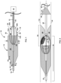
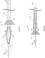
- FIG. 1 is a side view of an example thrombus removal device 10, which is configured to remove occlusive material within vasculature of a patient.
- FIG. 1 as well as many of the other figures are referred to herein as "side views," in some cases, portions of the devices are removed to show, for example, an inner lumen or the like. Thus, the side views may also be referred to as conceptual cross-sectional views in some cases.
- the thrombus removal device 10 can be used with any suitable treatment procedure.
- the thrombus removal device 10 can be used to remove a thrombus from within iliofemoral veins, central veins, upper extremity veins, peripheral large arteries, arteriovenous fistulae, or any other suitable target site within a patient.
- the thrombus removal device 10 includes an elongated expandable element support structure 12, an expandable element 14 disposed on the expandable element support structure 12, a stationary element 18, and a movable element 38 connected to a movable element support structure 60.
- the expandable element support structure 12 is fixedly connected to the expandable element 14 using any suitable technique.
- the expandable element 14 may be connected to the expandable element support structure 12 by an adhesive, solder, welding, crimped elements, such as bands or beads, and other suitable fixation mechanisms and/or elements or combinations thereof.
- the expandable element 14 may be formed directly onto the expandable element support structure 12, such as by incorporating one or more sections of the expandable element support structure 12 into a material forming the expandable element 14.
- the expandable element support structure 12 provides a structure by which a clinician may control the expandable element 14. For example, a clinician may grasp and manipulate a proximal portion of the expandable element support structure 12 to deploy the expandable element 14 from a delivery catheter and directly into a blood vessel of a patient, to move the expandable element 14 through a thrombus in the blood vessel, and to remove the expandable element 14 from the blood vessel.
- the expandable element support structure 12 may have any suitable length, such as, but not limited to, about 50 centimeters (cm) to about 100 cm, such as about 60 cm, about 75 cm, or about 90 cm (e.g., exactly these lengths or approximately these lengths to the extent permitted by manufacturing tolerances), and may be formed from any suitable material.
- the expandable element support structure 12 may be formed from a metal, a polymer, or combinations thereof.
- Example materials for the expandable element support structure 12 include, but are not limited to, nitinol (nickel titanium), stainless steel, cobalt-chromium-nickel molybdenum-iron alloy (e.g., commercially available under the trade designation Elgiloy TM available from Elgiloy Specialty Metals of Elgin, Illinois), carbon fiber and its composites, and engineered polymers such as liquid crystal polymers, polyether ether ketone (PEEK), polyamide, polyimide, polyester, and the like.
- PEEK polyether ether ketone
- the expandable element support structure 12 is sufficiently flexible to enable the thrombus removal device 10 to be navigated through the vasculature, which may be relatively tortuous in some cases, without kinking or becoming arrested by the vasculature en route to the treatment site.
- the expandable element support structure 12 may be solid in some examples, or may be hollow over some or all of its length.
- the expandable element support structure 12 defines an inner lumen configured to receive a guidewire 16.
- the guidewire 16 may be extended along a full length of the expandable element support structure 12 or may extend only along a portion of the expandable element support structure 12, e.g., in a rapid exchange-type configuration, and may be used to aid delivery of the thrombus removal device 10 to a treatment site within the vasculature of a patient.
- the expandable element support structure 12 may include a lumen and a plurality of holes (not shown) through which a physician may infuse or release a lytic agent to dissolve the thrombus 36.
- the physician may infuse a lytic agent from another component of the thrombus removal device 10, such as from a lumen of a movable element support structure 60, e.g., from between the movable element support structure 60 and the expandable element support structure 12, from a delivery catheter configured to deliver the thrombus removal device 10 to a target site within vasculature of a patient, from a retrieval catheter used to retrieve the thrombus removal device 10 from the target site, or any combination thereof.
- the expandable element 14 is configured to elongate and constrict in the longitudinal direction and/or expand in a radially outward direction.
- the expandable element 14 can be fixedly connected to a distal slider 32.
- the distal slider 32 may be configured to move relative to a proximal end 14A of the expandable element 14, such as by sliding along an outer surface of the expandable element support structure 12.
- the distal slider 32 has a tubular body or a partial-ring shape that fits around the outer surface of the expandable element support structure 12.
- the expandable element support structure 12 may include at least one mechanical stop that limits the relative proximal and distal sliding of the distal slider 32 of the expandable element 14.
- the ability of the expandable element distal end 14B to move relative to the expandable element proximal end 14A and relative to the expandable element support structure 12 may enable the expandable element 14 to conform to the inner wall of the peripheral vasculature while the expandable element support structure 12 is moving through the thrombus, during deployment, or retrieval of the expandable element support structure 12.
- a clinician can slide the expandable element distal end 14B proximally or distally relative to the proximal end 14A of the expandable element 14 so that the expandable element 14 more-closely adheres to the inner wall of a blood vessel.
- the expandable element 14 may be fixed to the expandable element support structure 12, such as by welding, adhesive, a mechanical connection, e.g., crimping a part of the expandable element 14 to the expandable element support structure 12.
- the expandable element 14 is configured to expand radially outward from a relatively low profile (e.g., relatively small radial profile) delivery configuration to an expanded deployed configuration.
- the expandable element 14 is configured to self-expand from the delivery configuration to the deployed configuration, e.g., in response to being released from an inner lumen of a delivery catheter.
- the compressive force applied to the expandable element 14 by the delivery catheter when the expandable element 14 is in the inner lumen may help hold the expandable element 14 in the delivery configuration.
- the expandable element 14 When the expandable element 14 is deployed from the inner lumen of the delivery catheter, the expandable element 14 may self-expand radially outward into its deployed configuration.
- the expandable element 14 may be formed from any suitable material, such as, but not limited to, nitinol.
- the expandable element 14 may be formed from a cut (e.g., a laser-cut) nitinol tube, e.g., similar to a stent, or from a nitinol mesh.
- a nitinol structure can be heat-set to assume a desired shape upon deployment within a patient.
- the expandable element 14 is not configured to self-expand and instead may be expanded with the aid of an expansion mechanism, such as, but not limited to, a balloon positioned inside an interior space of the expandable element 14 or via another actuation mechanism, such as a push or pull wire, connected to the expandable element 14.
- an expansion mechanism such as, but not limited to, a balloon positioned inside an interior space of the expandable element 14 or via another actuation mechanism, such as a push or pull wire, connected to the expandable element 14.
- the expandable element 14 may be formed from any suitable material, such as, but not limited to, stainless steel or a polymeric material.
- the expandable element 14 may be configured to assume a delivery configuration that enables the expandable element 14 to be delivered to a target site within vasculature of a patient using a relatively small profile delivery catheter, such as, but not limited to, an 8 French (Fr) catheter to a 12 Fr catheter, or another catheter having an outer diameter of less than or equal to about 4 mm.
- a relatively small profile delivery catheter may permit the catheter to pass distally through a thrombus 36 ( FIG. 2 ) to deploy the expandable element 14 on a distal side of the thrombus without creating large thrombus debris during the movement distally through the thrombus.
- a clinician may deploy the expandable element 14 from the delivery catheter on the distal side of the thrombus and withdraw the expandable element 14 proximally through the thrombus to capture at least part of the thrombus in the expandable element 14.
- relatively small profile delivery catheter may reduce interaction between the delivery catheter and one or more other medical devices implanted in the vasculature of the patient, such as an inferior vena cava (IVC) filter.
- IVC inferior vena cava
- the expandable element proximal end 14A may define a proximal mouth 20 configured to receive a thrombus, and/or the expandable element 14 may define a basket 22 configured to receive at least part of the thrombus after it has moved through the proximal mouth 20.
- the proximal mouth 20 may also be referred to as a "proximal-facing mouth” in some examples, because it provides an opening to the expandable element 14 in the proximal direction.
- the basket 22 may have a closed distal end 14B configured to retain at least part of the collected thrombus pieces.
- the expandable element 14 may be formed from any material that is suitably flexible and resilient to enable the expandable element proximal portion 14A to substantially conform to (e.g., conform or nearly conform to) a wall of a blood vessel 34 ( FIG. 2 ) when the expandable element 14 is deployed within the blood vessel.
- substantially conforming the basket 22 to the wall of a blood vessel may better enable the expandable element 14 to capture thrombi (e.g., pieces of a larger thrombus within the blood vessel) by increasing a size of the proximal mouth 20 through which the thrombi may enter the basket 22.
- a maximum cross-sectional dimension (e.g., a maximum diameter) of the proximal mouth 20 may be roughly the same point as the maximum cross-sectional dimension D 1 of the expandable element 14.
- the maximum cross-sectional dimension D 1 of the expandable element 14 in its deployed state, when unconstrained by a catheter lumen, a body lumen, or the like, may be selected based on the body lumen in which the thrombus removal device 10 is intended to be used.
- the maximum outer cross-sectional dimension D 1 of the expandable element 14 may be selected to be oversized relative to the body lumen, e.g., by 5% to 25%, such as about 10%, in order to enable the expandable element proximal end 14A to be in apposition to the wall of the body lumen when the device 10 is deployed in the body lumen.
- the apposition between the proximal end 14A (including the proximal mouth 20) and a blood vessel wall may help the thrombus removal device 10 collect a larger percentage of the thrombus.
- the maximum cross-sectional dimension D 1 is 20 mm
- the maximum cross-sectional dimension D 2 at the distal end 14B of the expandable element 14 is 2 mm.
- the example dimensions described herein for the thrombus removal device 10 are not exhaustive.
- An expandable element 14 having any suitable diameter may be employed and may be sized for deployment into the vasculature of any suitable subject.
- the expandable element 14 may have any suitable length, which can be measured from the proximal end 14A to the distal end 14B along a central longitudinal axis 28 of the expandable element support structure 12.
- the expandable element 14 has a length of about 50 mm to about 150 mm.
- the length is selected to facilitate a particular anatomical location.
- the expandable element 14 can have a length that enables the proximal end 14A of the expandable element 14 to be positioned at the base of the interior vena cava while keeping the distal end 14B out of the right atrium.
- the expandable element 14 can have a length of less than or equal to about 150 mm.
- the expandable element support structure 12 is positioned generally along the longitudinal axis 28, which extends from the proximal end 14A of the expandable element 14 to the distal end 14B of the expandable element 14.
- the expandable element 14 may define a plurality of openings 24 of uniform or various nonuniform dimensions.
- the expandable element 14 may be formed from a mesh or braided structure, or a cut (e.g., a laser-cut) tube.
- the plurality of openings 24 may be formed by mechanical means such as laser cut, drilling, and punching, by chemical means such as the selective dissolution of one or more components, or by virtue of a braided structure.
- suitable materials for the expandable element 14 may also include braided, knitted, woven, or non-woven fabrics that are capable of retaining particulate debris while permitting fluid to flow through the expandable element 14.
- Other suitable configurations for the expandable element 14 include a laser-cut frame, such as a laser-cut nitinol frame.
- the expandable element 14 may be used multiple times for the same patient (e.g., for multiple passes of the same thrombus or different passes of different thrombus), and cleaned between passes.
- a laser-cut frame may include fewer crossing points than a braided expandable element, which may make cleaning the expandable element 14 to remove any captured thrombus easier. Crossing points between filaments of a braid or other structure may trap parts of the thrombus and, thus, make cleaning of the expandable element 14 more difficult and time consuming.
- a braid may be more likely to elongate and decrease in diameter during cleaning compared to a laser cut tube (e.g., as the expandable element 14 is rinsed in saline or wiped to remove thrombus fragments). The decrease in the diameter of a braided expandable element may also make removing the thrombus fragments from the expandable element 14 during cleaning more difficult compared to a laser-cut tube.
- the expandable element 14 has a configuration that facilitates the withdrawal of the expandable element 14 into a sheath, e.g., to remove the expandable element 14 from the vasculature or to reposition the expandable element 14 within the vasculature.
- the expandable element 14 may be formed to be seamless (e.g., laser cut tube) and have closed cells. Seams or parts of an expandable element defining an open cell may catch on the distal end of a sheath during the resheathing process. Thus, eliminating seams and/or open cells may help facilitate easier resheathing of the expandable element.
- the plurality of openings 24 have an average maximum cross-sectional dimension that enables the expandable element 14 to retain pieces of a thrombus, while enabling fluid (e.g., blood) to flow through the openings 24.
- the plurality of openings 24 have an average maximum cross-sectional dimension of 1 mm to about 10 mm.
- the size of the openings 24 can depend on the vessel diameter to which the device 10 is apposed. In some examples, when the device 10 is configured to be expanded in apposition to a vessel having a 16 mm diameter, the openings 24 have an average maximum cross-sectional dimension of about 4mm to about 8mm.
- the maximum cross-sectional dimension being measured across the respective opening around the circumference (or other outer perimeter in the case of non-circular expandable elements 14) of the expandable element 14 at a given cross section of the overall device 10.
- the shapes of the openings 24 may dynamically change depending on a combination of any pressure applied from any foreign substance, such as a thrombus or other occlusive matter, and a material composition of the expandable element 14. For example, as the expandable element 14 is in the delivery configuration moving distally through a thrombus, the cross-sectional openings may be at a minimum dimension and, as the expandable element 14 is in the deployed configuration moving proximally through the thrombus, the openings 24 may increase in size.
- the basket 22 of the expandable element 14 may define an interior cavity 26 configured to receive and retain pieces of a thrombus via the proximal mouth 20.
- the plurality of openings 24 may be present in the portion of the expandable element 14 defining the basket 22.
- fluid e.g., blood
- the sizes of the openings 24 are constant throughout the basket 22, while in other examples, the average size of the openings 24 varies throughout the basket 22.
- the average size of the openings 24 may decrease from the proximal end 14A to the distal end 14B of the basket 22 to help prevent the escape of collected thrombus portions from the basket 22 during retrieval of the thrombus removal device 10 from a patient.
- an outer surface of the expandable element 14 may taper in a distal direction along a majority of the length of the basket 22.
- the expandable element 14 can taper in a distal direction along a majority of the length of the basket 22. This taper may define a conical shape of the basket 22, as shown in FIG. 1 .
- the expandable element 14 tapers from a diameter of about 20 mm at the proximal end 14A to a diameter of about 2 mm at the distal end 14B.
- the expandable element 14 may define a constant taper in the distal direction, as shown in FIG. 1 .
- the expandable element 14 defines a stepped taper or a gradual taper in the distal direction.
- the stepped taper may be achieved using any combination of geometries, such as, but not limited to, a proximal cylindrical segment followed by a proximal frustoconical segment, which can, in some cases, be followed by a distal cylindrical segment and a distal frustoconical segment.
- the gradual taper may be achieved using any combination of geometries, such as, but not limited to, a proximal frustoconical segment, followed by one or more additional frustoconical segments, at least two of the frustoconical segments having different degrees of taper.
- the taper segments e.g., the frustoconical segments
- the taper segments may be any angle (e.g., 10 degrees to 80 degrees) relative to a longitudinal axis of the expandable element support structure 12.
- the expandable element 14 is configured to contact an inner wall of the blood vessel when the expandable element 14 is deployed within the blood vessel. This may enable the expandable element 14 to both achieve some apposition with the blood vessel wall to capture more thrombus material, while reducing the adverse interaction between the expandable element 14 and the wall of the blood vessel as a clinician pulls the expandable element 14 proximally through the blood vessel 34 and through the thrombus 36. Overly contacting the vessel wall may lead to vessel spasms and adverse effects to the inner layer of the vessel, which may lead to further thrombosis.
- the length of the contact between the expandable element 14 and the vessel wall when the thrombus removal device 10 is deployed in the vessel is about 5 mm to about 50 mm, such as about 5 mm, 10 mm, or 50 mm.
- the length of the contact between the expandable element 14 and the wall of vessel 34 may increase with smaller-diameter vessels as the largest diameter (or other cross-sectional dimension) of the basket 22 will be compressed.
- the proximal end 14A (e.g., an outer perimeter of the proximal mouth 20) is configured to have an outward radial force greater than the radial force of the basket 22 of the expandable element 14 to help ensure apposition to the vessel wall.
- the basket 22 may be configured to exert less radial force, even if it contacts the vessel wall.
- the greater radial force may not only help ensure greater apposition with a vessel wall, but may also facilitate disruption of a thrombus.
- the greater radial force may be achieved using any suitable technique, such as, but not limited to, including a proximal ring that is configured to expand radially outward, e.g., in response to being released from an inner lumen of a delivery catheter.
- a thrombus may not be uniformly distributed within a blood vessel. Rather than relying on a clinician to guide the expandable element 14 to the side of the vessel wall that has the largest volume of the thrombus, the apposition of the circumference of the proximal mouth 20 and the blood vessel wall may help center the expandable element 14 in the vessel to capture a larger volume of thrombus.
- the expandable element 14 is configured to self-center in the vessel due at least in part to the proximal portion of the expandable element 14 being configured to stay in apposition with the vessel wall and/or being radially symmetric about longitudinal axis 28. This may enable the expandable element 14 to stay open and conform to vessel curvature when used with many clot types (e.g., which may have different densities) improving wall to wall contact.
- having only a relatively small length of the expandable element 14 configured to contact an inner wall of the blood vessel may enable the expandable element 14 to product less drag force (i.e., less force needed to be exerted by the clinician) to move the device 10 through the vessel.
- a proximal part of the expandable element 14, e.g., the proximal mouth 20, which may correspond to about the first 5 mm to about 20 mm of the expandable element 14, is configured to have more radial force to help ensure apposition to the vessel wall when the expandable element 14 is in the deployed configuration in the blood vessel.
- the remaining distal length of the expandable element 14 is configured to exert less radial force than the proximal part to enable the remaining distal length pass more passively through the vessel 34.
- the expandable element 14 is configured to compress at least a part of the thrombus received within the basket 22 as the expandable element 14 is proximally withdrawn into a catheter.
- a thrombus may have a relatively large liquid content.
- fluid may be expelled from the thrombus and dehydrate the thrombus, such that the volume of the thrombus retained in the basket 22 is decreased.
- Decreasing the volume of the thrombus in the basket 22 may help increase the ease with which the expandable element 14 may be withdrawn proximally into the inner lumen of a catheter to withdraw the thrombus from the patient.
- the tapered shape of the expandable element 14 may help distribute the thrombus longitudinally within the basket 22 as the expandable element 14 is proximally withdrawn into a catheter, which may help mitigate the possibility of having too much relatively rigid material (e.g., the dehydrated thrombus) at the distal-most end 14B of the basket 22.
- a relatively large bulk of relatively rigid material at the distal-most end of the basket 22 may interfere with the proximal withdrawal of the expandable element 14 into a retrieval catheter.
- the thrombus may be captured within the basket 22 and then compressed within the expandable element 14 as the thrombus is forced toward the distal end 14B of the expandable element 14. As noted above, this compression may expel liquid within the thrombus as the expandable element 14 elongates while the expandable element support structure 12 moves proximally through a blood vessel 34.
- the distribution of the thrombus longitudinally within the basket 22, as well as the compression of the thrombus within the basket 22 may help the expandable element 14 retain and remove a relatively large thrombus from a blood vessel of a patient for a given size of the expandable element 14.
- the thrombus removal device 10 includes a stationary element 18 and a movable element 38.
- the movable element 38 is configured to move relative to the stationary element 18.
- the stationary element 18 includes a plurality of elongated arms 18A-18N. In the example shown in FIG. 1 , each of the arms 18A-18N has proximal and distal ends extending from (e.g., mechanically coupled to) the expandable element support structure 12.
- the proximal and distal ends of the stationary element 18 may be configured to have fixed longitudinal and rotational positions relative to the expandable element support structure 12.
- each of the arms 18A-18N may be configured to extend radially outward, away from the expandable element support structure 12, into an expanded or deployed configuration in order to segment a thrombus 36 ( FIG. 2 ) into a plurality of pieces (e.g., two or more smaller thrombus portions) as the stationary element 18 is moved proximally through the thrombus 36.
- the central portions of arms 18A-18N may be configured to, as a group, span across the entire area of occlusion of the proximal mouth 20 of the expandable element 14 to well under 10% of the cross-sectional area of the proximal mouth 20 (the cross-section being taken in a direction orthogonal to the longitudinal axis 28), enabling the arms 18A-18N to segment the thrombus 36 with minimal force without impeding the thrombus pieces from entering the mouth 20.
- the stationary element 18 includes three elongated arms, each having a cross-sectional width (the cross-section being taken in a direction orthogonal to longitudinal axis 28) of about 0.25mm. Minimizing the area of contact between the thrombus 36 and the stationary arms 18A-18N may facilitate the shearing process of the stationary arms 18A-18N as they pass through and segment the thrombus 36.
- the stationary arms 18A-18N may have any suitable radial spacing, e.g., be evenly distributed around the central longitudinal axis 28 (e.g., for three stationary arms 18A-18N, the stationary arms may be 120 degrees apart from each other) or may be unevenly distributed around the central longitudinal axis 28.
- the number of stationary arms 18A-18N and the radial spacing between the stationary arms 18A-18N may be selected to enable the proximal mouth 20 of the expandable element 14 to remain relatively open, centered around the expandable element support structure 12, and to enable pieces of the thrombus 36 to move distally into the basket 22 rather than being captured and retained within the spaces between the stationary arms 18A-18N.
- the number of the stationary arms 18A-18N may be selected to enable the thrombus 36 to be segmented into sufficiently small pieces ( FIG. 2 ) for collection in the basket 22 after moving distally through the proximal mouth 20.
- some or all of the plurality of stationary arms of stationary element 18 may be integrally formed with the expandable element 14.
- some or all of the stationary arms 18A-18N and the expandable element 14 may be formed from a common piece of material (e.g., a nitinol tube).
- some or all of the stationary arms 18A-18N may be formed separately from the expandable element 14 and remain separate or may be subsequently connected to expandable element.
- some or all of the stationary arms 18A-18N may be formed separate from the expandable element 14 and may be connected to a point at or near the circumference of the proximal mouth 20 of the expandable element 14 using any suitable technique, such as, but not limited to, adhesives, solder, welding, crimped elements, such as bands or beads, and other suitable fixation mechanisms and/or elements.
- a central portion of some or all of the stationary arms 18A-18N may be coupled to a rim or circumference of proximal mouth 20 of expandable member 14.
- a distal end of some or all of the stationary arms 18A-18N may be coupled to a rim or circumference of proximal mouth 20 of expandable member 14.
- the plurality of stationary arms 18A-18N may be formed from the same material or substantially the same material as the expandable element 14.
- the stationary arms of stationary element 18 may be formed separate from or may be integrally formed with the expandable element support structure 12.
- the proximal and/or distal ends of each stationary arm 18A-18N may be connected to the expandable element support structure 12 using any suitable technique, such as by an adhesive, solder, welding, crimped elements, such as bands or beads, and other suitable fixation mechanisms and/or elements.
- the arms 18A-18N of the stationary element 18 may be configured to remain rotationally and/or longitudinally stationary relative to a part of the expandable element 14 (e.g., the proximal mouth 20) and/or the expandable element support structure 12.
- the movable element 38 is configured to move relative to the stationary element 18 and macerate the thrombus 36 after the stationary element 18 segments the thrombus 36 into smaller pieces (relative to the state before the use of thrombus removal device 10).
- the stationary element 18 is configured to segment the thrombus 36 into smaller pieces and the movable element 38 is configured to break the smaller pieces into even smaller pieces.
- the movable element 38 is located radially inward from the stationary element 18, e.g., closer to the central longitudinal axis 28 of the expandable element support structure 12 than the stationary element 18. As shown in FIG. 1 , the movable element 38 may be positioned within a volume 80 defined by the stationary arms 18A-18N of the stationary element 18. Thus, the movable element 38 has a greatest cross-sectional dimension (e.g., a diameter) that is smaller than a greatest cross-sectional dimension of the movable element 18, the cross-sections being taken in a direction orthogonal to the longitudinal axis 28 when the elements 18, 38 are in an expanded (deployed) configuration.
- a greatest cross-sectional dimension e.g., a diameter
- the movable element 38 has a greatest cross-sectional dimension (e.g., a diameter) that is smaller than a greatest cross-sectional dimension of the movable element 18 when the elements 18, 38 are in a collapsed (delivery) configuration.
- the stationary arms 18A-18N may be configured to be positioned between the movable element 38 and the wall of the blood vessel 34 to protect the wall of the vessel 34 from the movable element 38, while still enabling the thrombus 36 to move into the volume 80 between adjacent stationary arms 18A-18N to contact the movable element 38.
- the movable element 38 may take the form of any suitable configuration and be configured to (e.g., be controllable to) move relative to the stationary element 18 according to any suitable motion pattern in order to more-thoroughly break down the thrombus 36.
- FIG. 1 depicts a first non-limiting example of the movable element 38.
- the movable element 38 includes a second plurality of elongated arms 38A-38N (e.g., "movable arms 38A-38N”) having distal ends extending from (e.g., slidably or mechanically coupled to) the expandable element support structure 12.
- a proximal end of each of the movable arms 38A-38N may be connected to an elongated movable element support structure 60 that is configured to transfer a movement (e.g., rotation, vibration, and/or plunging movement) to the movable element 38 from an actuator device 66 at a proximal portion of the thrombus removal device 10.
- a movement e.g., rotation, vibration, and/or plunging movement
- the actuator device 66 can include any suitable motor and control circuitry configured to generate movement and transfer the motion to movable element 38 via movable element support structure 60.
- the actuator device 66 may also include, for example, a user-input mechanism communicatively coupled to the control circuitry.
- the control circuitry as well as other processors, processing circuitry, controllers, control circuitry, and the like, described herein, may include any combination of integrated circuitry, discrete logic circuity, analog circuitry, such as one or more microprocessors, digital signal processors (DSPs), application specific integrated circuits (ASICs), or field-programmable gate arrays (FPGAs).
- control circuitry 42 may include multiple components, such as any combination of one or more microprocessors, one or more DSPs, one or more ASICs, or one or more FPGAs, as well as other discrete or integrated logic circuitry, and/or analog circuitry.
- the movable element support structure 60 can be, for example, a tube that is positioned radially outward of the expandable element support structure 12 to which the expandable element 14 is connected.
- the movable element support structure 60 is configured to move independently of the expandable element support structure 12.
- a distal end of each of the movable arms 38A-38N may be connected to a distal movable element support structure 92, which is configured to move with the movable element 38 (e.g., rotate about the central longitudinal axis 28, vibrate, and/or move longitudinally along the central longitudinal axis 28) and move relative to stationary element 18.
- the distal movable element support structure 92 can be, for example, a tubular or ring-like structure that fits around the expandable element support structure 12 and is configured to rotate about the central longitudinal axis 28 relative to the expandable element support structure 12 as the movable element 38 similarly rotates and/or move longitudinally relative to the stationary arms 18A-18N along a direction parallel to the central longitudinal axis 28 as the movable element 38 similarly moves longitudinally.
- each of the movable arms 38A-38N may be configured to spread radially outward from the expandable element support structure 12 in order to macerate the thrombus 36 ( FIG. 2 ) into a plurality of pieces (e.g., two or more smaller pieces) while the movable arms 38A-38N move relative to the stationary element 18.
- the movable arms 38A-38N of movable element 38 may be configured, according to various non-limiting examples, to rotate about the longitudinal axis 28 and relative to the stationary element 18, to oscillate parallel to the longitudinal axis 28 and relative to the stationary element 18 (while remaining within the volume 80 defined by the stationary element 18), to vibrate radially inward and outward from the longitudinal axis 28 and relative to the stationary element 18, and/or to plunge proximally and distally along longitudinal axis 28 and relative to the stationary element 18 in order to macerate the thrombus 36.
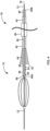
- FIG. 2 is a conceptual illustration of the example stationary element 18 and the example movable element 38 of FIG. 1 while segmenting and macerating an example thrombus 36 into a plurality of smaller pieces. More specifically, FIG. 2 is a conceptual side elevation view of the expandable element 14, the stationary element 18, and the movable element 38 moving proximally (to the right, from the perspective shown in FIG. 2 ) through the thrombus 36 and illustrates the thrombus pieces after they have been separated from a larger thrombus portion and as they are entering the basket 22 of the expandable element 14.
- stationary element 18 and movable element 38 are fully expanded into a deployed configuration (as compared to a partially expanded configuration as shown in FIG. 1 ), such that a diameter of the stationary element 18 extends approximately the full width of a vessel 34 of a patient into which the thrombus removal device 10 has been inserted.
- the stationary element 18 may define a diameter (transverse to longitudinal axis 28) that is less than, approximately equal to, or greater than the diameter of proximal mouth 20 of the expandable element 14.
- the diameter of stationary element 18 and proximal mouth 20 are both approximately equal to the width of the vessel 34 while in their respective deployed configurations.
- FIG. 2 Also shown in FIG. 2 is a delivery catheter 40, a retrieval catheter 42 defining or otherwise including a funnel 44, and a cover sheath 46.
- the entire length of the catheters 40, 42, and the cover sheath 46 is not shown in the figures.
- the retrieval catheter 42 shown in FIG. 2 is shown to be relatively short, but may in use have a length long enough to extend from a target site within a patient to a location outside of the patient.
- Separating the thrombus 36 into a plurality of smaller thrombus portions may enable more-effective capture of the thrombus 36 within the basket 22, particularly when the thrombus 36 may be a sub-acute thrombus that is more organized and/or vessel-wall-adherent compared to a more-newly formed acute thrombus, which may be softer.
- separating the thrombus 36 into a plurality of smaller thrombus portions may enable a smaller delivery and/or retrieval catheter to be used to deliver or withdraw, respectively, the thrombus removal device 10 from the patient.
- a clinician may move the expandable element support structure 12, and as a result, the fixedly connected stationary element 18, and the movable element 38 (in their respective deployed configurations) proximally through the thrombus.
- the elongated stationary arms 18A-18N of stationary element 18 will come in contact with a distal portion of the thrombus 36 and segment the thrombus 36 into smaller pieces (e.g., will cleave one or more sections from the larger occlusive mass).
- the movable element 38 will come into contact with a distal portion of the thrombus 36, and through a pre-defined motion (e.g., a rotational motion, as depicted in the example of FIG. 2 ), the movable element 38 will macerate the distal portion of the thrombus 36 into even smaller portions, at least some of which are then received in the proximal mouth 20 of the expandable element 14. As the proximal mouth 20 receives the macerated thrombus portions, the macerated thrombus portions will move distally within the expandable element 14 through the basket 22, where the thrombus portions may be retained.
- a pre-defined motion e.g., a rotational motion, as depicted in the example of FIG. 2
- one or more disassociated segments of the thrombus 36 may become entangled within the one or more of the openings 24 defined by the expandable element 14. For example, as the part of the thrombus 36 within the basket 22 becomes compressed, some of the thrombus may be squeezed out one or more of the openings 24. However, even these parts of the thrombus 36 extending through the one or more openings 24 may still be considered captured within the basket 22. For example, the more rigid dehydrated thrombus extending through the opening 24 may be less likely to separate from the expandable element 14 and flow downstream.
- the thrombus removal device 10 can include an atraumatic distal tip that is configured to soften an interface between the distal tip and adjacent tissue of a patient.
- the thrombus removal device 10 can include a distal tip member 30 at or near a distal end of the expandable element support structure 12.
- the distal tip member 30 can be formed from any suitable material, such as, but not limited to, a relatively soft polymer that is softer than the material forming the expandable element support structure 12.
- the distal tip member 30 may also act as the distal slider 32, which is configured to movably connect the distal end 14B of the expandable element 14 to the expandable element support structure 12 and is configured to slide relative to the expandable element support structure 12.
- the configuration (e.g., shape, dimensions, and the like) and the composition (e.g., material) of the thrombus removal device 10, including the expandable element support structure 12, the expandable element 14, the stationary element 18, and the movable element 38, of the examples described herein are merely one example.
- the expandable element 14, the expandable element support structure 12, the stationary element 18, and/or the movable element 38 may have another configuration.
- each of the arms 18A-18N of the stationary element 18 has proximal and distal ends extending from (e.g., mechanically coupled to) the expandable element support structure 12.
- some or all of the arms 18A-18N may be connected to another structure of the thrombus removal device 10.
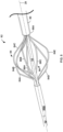
- FIG. 3 is a conceptual side elevation view of another example thrombus removal device 62.
- the thrombus removal device 62 is similar to the thrombus removal device 10 of FIGS.
- the thrombus removal device 62 includes a stationary element 64 including elongated stationary arms 64A-64N that are mechanically coupled to the expandable element support structure 12 at a proximal end of the respective stationary arm 64A-64N and are coupled to the rim of proximal mouth 20 of expandable element 14 at a distal end of the respective stationary arm 64A-64N.
- the stationary arms 18A-18N of the thrombus removal device 10 of FIGS. 1 and 2 are mechanically coupled to the expandable element support structure 12 at both proximal and distal ends.
- the stationary element 64 and the expandable element 14 may be mechanically integrated, such that stationary element 64 and expandable element 14 are configured to convert between a delivery configuration and a deployed or expanded configuration in concert with one another.
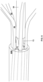
- FIG. 4 is a conceptual side elevation view of the example thrombus removal device 10 of FIGS. 1 and 2 and a catheter assembly 78, where the expandable element 14 has been removed from the figure to show details of the stationary element 18 and the movable element 38.
- FIG. 4 is described with reference to the thrombus removal device 10 of FIGS. 1 and 2 , in other examples, the catheter assemblies and techniques described herein can be used with the other example the thrombus removal devices described herein, including the thrombus removal device 62 of FIG. 4 .
- the catheter assembly 78 includes the delivery catheter 40, the retrieval catheter 42 defining or otherwise including the funnel 44, and the cover sheath 46 configured to cover the funnel 44 and hold the funnel 44 in a low-profile configuration for delivery of the catheter assembly 78 to a target site.
- the entire length of the structures shown in FIG. 4 are not shown.
- the retrieval catheter 42 is shown to be truncated in length.
- the delivery catheter 40, the retrieval catheter 42, and the cover sheath 46 are shown as being nested relative to each other in FIG.
- a clinician may deliver the thrombus removal device 10 to a target site within a patient over the guidewire 16 and while the device 10 is within a lumen 48 of the delivery catheter 40, and then, at a later time, introduce the retrieval catheter 42 and cover sheath 46 into the patient over the guidewire 16 or the delivery catheter 40 at a later time, e.g., after thrombus is collected in the basket 22 of the thrombus removal device 10.
- the clinician may deliver the thrombus removal device 10 with the delivery catheter 40, the retrieval catheter 42, and the cover sheath 46 nested together.
- each of the catheters 40, 42 may have a tubular catheter body that defines a respective lumen 48, 50.
- one or both catheters 40, 42 may be a multi-lumen catheter that defines a plurality of lumens.
- the catheters 40, 42 may be formed from any suitable material, such as, but not limited to, such as poly(tetrafluoroethylene) (PTFE), polyethylene (PE), high density polyethylene (HDPE), low density polyethylene (LDPE), other flexible plastic blends or thin-walled metal alloys or combinations thereof.
- PTFE poly(tetrafluoroethylene)
- PE polyethylene
- HDPE high density polyethylene
- LDPE low density polyethylene
- the delivery catheter lumen 48 is configured to contemporaneously receive the thrombus removal device 10, including the guidewire 16, the expandable element 14, the stationary element 18, and the movable element 38, as well as part of the expandable element support structure 12.
- the walls of the delivery catheter 40 apply a compressive force to the thrombus removal device 10 to hold the thrombus removal device 10 in a relatively low profile delivery configuration.
- the thrombus removal device 10 is shown in its deployed configuration, after it has been deployed from a distal end 40A of the delivery catheter 40.
- a clinician may push the thrombus removal device 10 from the delivery catheter lumen 48 by applying a pushing force to a proximal portion of the expandable element support structure 12 proximally extending from a proximal end 40B of the delivery catheter 40.
- the expandable element support structure 12 is rigid enough to move distally out the delivery catheter distal end 40A in response to the pushing force.
- the clinician may deploy the thrombus removal device 10 from the delivery catheter 40 by at least proximally withdrawing the delivery catheter 40 relative to the expandable element 14, e.g., while holding the thrombus removal device 10 in place or nearly in place via the expandable element support structure 12.
- the retrieval catheter 42 may be configured to receive the thrombus removal device 10 after thrombus is collected in the basket 22 of the expandable member 14 ( FIGS. 1 and 2 ).
- the retrieval catheter lumen 50 may be configured to contemporaneously receive the guidewire 16, the expandable element 14, the stationary element 18, and the movable element 38, as well as part of the expandable element support structure 12 and, in some examples, the delivery catheter 40. However, the delivery catheter 40 and/or the guidewire 16 may be removed from the patient prior to introducing the retrieval catheter 42 over the expandable element support structure 12 of the thrombus removal device 10.
- the funnel 44 may be positioned at a distal portion (e.g., a distal end) of the retrieval catheter 42 and may be configured to facilitate the proximal withdrawal of the expanded thrombus removal device 10 into the retrieval catheter lumen 50.
- the funnel 44 defines a relatively large distal funnel mouth 52 and the funnel 44 tapers in a proximal direction from the distal funnel mouth 52.
- the tapered shape of the funnel 44 guides the thrombus removal device 10 from the distal funnel mouth 52 into the retrieval catheter lumen 50, while compressing the thrombus removal device 10 from the deployed configuration to a smaller profile configuration, e.g., the delivery configuration or a retrieval configuration that is smaller in profile than the deployed configuration but may be larger in profile than the delivery configuration due to the presence of collected occlusive material within the basket 22 of the expandable element 14.
- a smaller profile configuration e.g., the delivery configuration or a retrieval configuration that is smaller in profile than the deployed configuration but may be larger in profile than the delivery configuration due to the presence of collected occlusive material within the basket 22 of the expandable element 14.
- the catheter assembly 78 may include a cover sheath 46 that is configured to apply a compressive force to the funnel 44. Once the cover sheath 46 is proximally withdrawn so that it no longer covers the funnel 44, the funnel 44 may expand radially outward into the funnel shape shown in FIG. 4 .
- the funnel 44 may have a self-expandable frame, e.g., formed from nitinol struts, a nitinol mesh, or a nitinol braid or another suitable material, that is shape set to the funnel shape.
- the funnel 44 may be expanded radially outward with the aid of an expansion mechanism, such as a balloon.
- the funnel 44 is configured to be re-introduced into the cover sheath 46 after it is deployed from the cover sheath 46, such as by withdrawing the funnel 44 proximally into the cover sheath 46, by moving the cover sheath 46 distally over the funnel 44, or any combination thereof. Resheathing the funnel 44 in this manner may facilitate removal of the funnel 44 from the vasculature of the patient or an adjustment of the position of the funnel 44 within the vasculature.
- the funnel 44 can have a configuration that facilitates resheathing.
- the funnel 44 can have a closed cell braid pattern (e.g., no open strands at the proximal end) that is less likely to catch on the distal end of the cover sheath 46 than open cells as the funnel 44 is re-introduced into the cover sheath 46.
- a closed cell braid pattern e.g., no open strands at the proximal end
- the retrieval catheter 42 includes a plurality of pores configured to enable liquid to exit the retrieval catheter inner lumen 50 and into, e.g., the blood stream.
- the pores may be positioned along the funnel 44 and/or along a sidewall of the catheter 42 proximal to the funnel 44.
- the liquid may be expelled from thrombus within the basket 22 as the expandable element 14 is proximally withdrawn into the funnel 44.
- the plurality of pores of the retrieval catheter 42 may have a size sufficient to permit fluid to flow out of the retrieval catheter inner lumen 50 and may have any suitable shape (e.g., oval, circular, square, rectangular, triangular, or an irregular shape).
- the plurality of pores can be defined by a sidewall of the retrieval catheter 42 and having a greatest cross-sectional dimension (e.g., a diameter in the case of circular pores) of about 1 mm to about 10 mm, such as about 5 mm.
- the delivery catheter 40 may have a smaller profile (e.g., outer diameter or other maximum outer cross-sectional dimension) than the retrieval catheter 42. This may be due at least in part to needing to accommodate the expandable element 14 after pieces of a thrombus are positioned within the basket 22, thereby increasing an overall profile of the expandable element 14.
- the clinician may leave the delivery catheter 40 in the blood vessel 34 ( FIG. 2 ) during retrieval of the thrombus 36 and may deliver a therapeutic agent, e.g., a lytic agent, through the delivery catheter lumen 48 to the target site.
- a therapeutic agent e.g., a lytic agent
- the therapeutic agent may be introduced into the delivery catheter lumen 48 at a proximal portion of the catheter 40 and delivered to the target site via an opening at a distal-most end of the delivery catheter 40, through one or more side openings 54 defined by a sidewall of the delivery catheter 40 (e.g., distributed along a wall of the delivery catheter 40 extending along a length of the expandable element support structure 12 or a part of the delivery catheter 40), or any combination thereof.
- the sidewall 56 of the delivery catheter 40 defines a plurality of side openings 54 that are distributed (evenly or unevenly) along only a portion of the delivery catheter sidewall 56 that is proximal to the expandable element 14 when the expandable element 14 is disposed in the delivery catheter lumen 48.
- the side openings 54 can also be defined in the portion of the sidewall 56 that longitudinally aligns with the expandable element 14 when the expandable element 14 is disposed in the delivery catheter lumen 48 and/or the portion of the sidewall that is distal to the expandable element 14.
- side openings 54 on one longitudinal side of the sidewall 56 are shown in FIG. 4 , in some examples, the side openings 54 may be disposed on the other longitudinal side of the sidewall 56, too (e.g., distributed around an outer circumference of the delivery catheter 40 in examples in which the delivery catheter 40 is circular in cross-section).
- the therapeutic agent is delivered via the delivery catheter lumen 48 after deploying the thrombus removal device 10, i.e., while the thrombus removal device 10 is no longer in the delivery catheter lumen 48.
- the therapeutic agent is delivered via the delivery catheter lumen 48 prior to deploying the thrombus removal device 10, for example, while the thrombus removal device 10 is still in the delivery catheter lumen 48.
- the delivery catheter 40 can include a seal 58 positioned distal to the side openings 54 and proximal to the thrombus removal device 10 to help prevent the therapeutic agent from being delivered out a distal-most opening of the delivery catheter 40.
- the seal 58 may create a fluid-tight barrier that helps prevent the therapeutic agent from passing distally past the seal 58 towards the thrombus removal device 10.
- the delivery catheter 40 may not include a seal 58 and instead the therapeutic agent may be free to be delivered out the distal-most opening of the delivery catheter 40 in addition to out of the side openings 54.
- the therapeutic agent is delivered via the delivery catheter lumen 48 after deploying the thrombus removal device 10, e.g., while the thrombus removal device 10 is no longer in the delivery catheter lumen 48.
- FIG. 5 is a perspective view of a portion of an example thrombus removal device 82.
- the thrombus removal device 82 is an example of the thrombus removal device 10 of FIGS. 1 and 2 .
- the thrombus removal device 82 includes the expandable element support structure 12, a stationary element 84, a movable element 86, a proximal end cap 88A, and a distal end cap 88B.
- the stationary element 84 includes five elongated stationary arms 84A-84E, however, the stationary element 84 may include any number of stationary arms in other examples.
- the proximal and distal ends of the stationary arms 84A-84E are connected to the expandable element support structure 12.
- the stationary arms 84A-84E extend generally in a proximal-to-distal direction.
- the proximal and distal ends of each respective stationary arm 84A-84E are aligned in a direction parallel to the longitudinal axis 28, such that the stationary arms are parallel to the longitudinal axis 28.
- the one or more of the stationary arms 84A-84E may have misaligned proximal and distal ends such that respective stationary arms wrap circumferentially around an outer perimeter of the expandable element support structure 12 (e.g., defining part of a helix). In the deployed configuration shown in FIG.
- a central portion of each of the stationary arms 84A-84E is configured to slice longitudinally through a thrombus 36 ( FIG. 2 ) as the thrombus 36 passes through the stationary element 84, or as the stationary element 84 passes through the thrombus 36.
- the movable element 86 includes three elongated movable arms 86A-86C.
- the movable element 86 may include any number of movable arms, or in other examples, configurations other than, or additional to, elongated arms.
- the movable arms 86A-86C may extend in a generally proximal-to-distal direction, and also generally wrap circumferentially around the central longitudinal axis 28, e.g., in a helical-type configuration. That is, in the example shown in FIG.
- each movable arm 86A-86C are not aligned in a direction parallel to the longitudinal axis 28, such that the movable arms are not parallel to the longitudinal axis 28. In other examples, however, proximal and distal ends of some or all of the movable arms 86A-86C may be aligned in a direction parallel to the longitudinal axis 28.
- a proximal end of the stationary element 84 is mechanically coupled to a proximal end cap 88A disposed on the expandable element support structure 12.
- a distal end of the stationary element 84 and/or of the movable element 86 may be mechanically coupled to a distal end cap 88B disposed on the expandable element support structure 12.
- the distal end cap 88B may include a plurality of slots configured to rigidly retain distal portions of the stationary arms 84A-84E.
- the distal end cap 88B includes a ring structure 92, such as a rotatable tube configured to rigidly retain distal portions of the movable arms 86A-86C, enabling the movable element 86 to rotate about the expandable element support structure 12 and relative to the stationary element 84.
- a ring structure 92 such as a rotatable tube configured to rigidly retain distal portions of the movable arms 86A-86C, enabling the movable element 86 to rotate about the expandable element support structure 12 and relative to the stationary element 84.
- the movable element 86 may be configured to move relative to the stationary element 84, and move within a volume defined by the stationary element 84, in order to macerate a thrombus 36 ( FIG. 2 ) as the movable element 86 passes through the thrombus 36 (or as the thrombus 36 passes through the movable element 86).
- the movable element 86 may be configured to move according to a predetermined motion pattern in order to macerate the thrombus 36. That is, the thrombus removal device 82 may be mechanically coupled to one or more control elements, such as actuator 66 ( FIG. 1 ) configured to cause the movable element 86 to move according to a pre-determined pattern. As shown in FIG.
- a proximal end of each of the elongated arms of movable element 86 may be coupled to an elongated movable element support structure 60, which is configured to transfer a motion from the actuator 66 or other control device to movable element 86.
- the actuator device 66 may include a motor configured to cause the movable arms 86A-86C to rotate about the longitudinal axis 28 and relative to the stationary element 84.
- the movable arms 86A-86C may be configured to spin within the volume defined by the stationary element 84 under the control of the actuator 66.
- the actuator 66 can be configured to cause the movable element 86 to "plunge" back-and-forth (proximally and distally) in a direction generally parallel to the longitudinal axis 28 and relative to the stationary element 84, e.g., oscillating between proximal and distal directions of motion.
- the actuator 66 can be configured to cause the movable arms 86A-86C to vibrate radially inward and outward from the longitudinal axis 28 and relative to the stationary element 84.
- the actuator 66 and the movable element 86 are configured to enable the movable element 86 to move relative to the stationary element 84 according to a pre-determined combination of any or all of these example motion patterns.
- the movable arms 86A-86C may be configured to move according to an arc-shaped motion, e.g., vibrating radially inward and outward and simultaneously in a circumferential direction.
- FIGS. 7A and 7B are conceptual diagrams depicting a method of collapsing an example thrombus removal device 10 from a deployed configuration to a delivery configuration.
- the expandable element 14 is shown in phantom lines in FIGS. 7A and 7B to better show the stationary element 18 and the movable element 38.
- FIG. 7A depicts the stationary element 18 and the movable element 38 in a partially-deployed (e.g., partially expanded) configuration, in which a central portion of the stationary element 18 and the movable element 38 expanded spread radially outward from an elongated expandable element support structure 12.
- the expandable element 14 is in a deployed configuration so as to define a basket shape having an open internal volume configured to receive and/or collect portions of a thrombus.
- the stationary element 18 and the movable element 38 have been collapsed radially inward from the deployed configuration to a delivery configuration (e.g., a collapsed or contracted state).
- the thrombus removal device 10 may include a pull wire or other mechanism (not shown) configured to convert the thrombus removal device 10 between the delivery configuration and the deployed configuration.
- each of the expandable element 14, the stationary element 18, and the movable element 38 may include a separate or distinct pull member or other user-input mechanism configured to cause the respective element to convert between the delivery configuration and the deployed (expanded) configuration.
- a manual expansion mechanism may enable or enhance outward radial support to the expandable element 14 and stationary element 18 while the physician pulls them proximally through a thrombus, preventing the thrombus from causing them to collapse radially inward while segmenting and macerating the thrombus.
- each of the expandable element 14, the stationary element 18, and the movable element 38 are configured to self-expand when extended outward from a delivery catheter, and configured to contract to a more compressed configuration under the compression force applied by the retrieval catheter 42 (e.g., the funnel 44 of the retrieval catheter 42) when proximally withdrawn back into the retrieval catheter 42.
- the more compressed configuration may be referred to as a "delivery" configuration, although the thrombus removal device may have a different maximum cross-sectional dimension during delivery via the delivery catheter and retrieval via the retrieval catheter 42. While in the delivery configuration shown in FIG.
- the stationary element 18 and the movable element 38 both define a maximum cross-sectional dimension (the cross section taken in a direction transverse to the longitudinal axis 28) that is sufficiently small to enable the stationary element 18 and the movable element 38 to be proximally withdrawn into the retrieval catheter 42.
- expandable element 14 may be collapsed from a deployed configuration to a delivery configuration and may be proximally withdrawn into the retrieval catheter 42 in order to remove any captured thrombus portions from the body of the patient.
- FIGS. 8A-8E depict example configurations of a movable element of a thrombus removal device. More specifically, FIGS. 8A-8E each depict a different example shape of one or more elongated arms, which may each be examples of an elongated arm 86A of FIG. 5 .
- FIG. 8A depicts an elongated arm 94A that has a parabolic shape while in a deployed configuration.
- Proximal end 68A and distal end 68B of elongated arm 94A may be generally longitudinally aligned along a direction parallel to the central longitudinal axis 28 of the elongated expandable element support structure 12, or may be slightly offset such that the elongated arm 94A extends across a small portion of the circumference of the elongated expandable element support structure 12.
- FIG. 8B depicts another example elongated arm 94B that has a sinusoidal shape while in a deployed configuration.
- Proximal end 70A and distal end 70B of the elongated arm 94B may be generally longitudinally aligned along a direction parallel to the central longitudinal axis 28 of the elongated expandable element support structure 12, or may be slightly offset such that the elongated arm 94B extends across a small portion of the circumference of the elongated expandable element support structure 12.
- FIG. 8C depicts an example elongated arm 94C that defines a bell-curve shape while in a deployed configuration.
- Proximal end 72A and distal end 72B of the elongated arm 94C may be generally longitudinally aligned along a direction parallel to the central longitudinal axis 28 of the elongated expandable element support structure 12, or may be slightly offset such that the elongated arm 94B extends across a small portion of the circumference of the elongated expandable element support structure 12.
- FIG. 8D depicts an example elongated arm 94D that defines a helical shape that wraps circumferentially around the longitudinal axis 28 while in a deployed configuration (similar to the elongated arms 86A-86C of the movable element 86 of FIG. 4 ).
- Proximal end 74A and distal end 74B of the elongated arm 94D may be generally offset along a direction parallel to the central longitudinal axis 28 such that the elongated arm 94D extends completely around the complete circumference of the elongated expandable element support structure 12 at least a single time (e.g., at least one complete turn around the circumference).
- FIG. 8E depicts an example movable element having a plurality of elongated arms 94E that extend radially outward from central longitudinal axis 28 while in a deployed configuration.
- the movable element defines a brush-type structure, in which each of elongated arms 94E defines a respective bristle of the brush structure.
- Each of elongated arms 94E may be relatively flexible, and be attached at one end to a movable element support structure 60.
- elongated arms 94E may be arranged around the entire circumference of movable element support structure 60.
- movable element support structure 60 may be configured to rotate about central longitudinal axis 28, causing elongated arms 94E to similarly rotate about axis 28.
- one or more of the elongated arms of the movable element and/or the stationary elements described herein may include different types of surface textures, which may impart different types of results to the maceration of a thrombus by the respective arm.
- FIG. 9A depicts a first example surface texture 96A for an elongated arm of a thrombus removal device 10.
- the surface texture 96A is primarily smooth or planar, reducing an amount of contact (e.g., friction) between the respective elongated arm and a thrombus 36, which in some cases, may enable the elongated arm to slice more smoothly or easily through the thrombus 36 (e.g., cleave apart two distinct portions of the thrombus 36 while leaving the individual portions generally intact).
- an amount of contact e.g., friction
- FIG. 9B depicts another example surface texture 96B for an elongated arm of a thrombus removal device 10.
- the surface texture 96B defines an "open pitch cable" surface, wherein an elongated wire 98 is loosely helically coiled around the respective elongated arm so as to define a gap in between each adjacent loops of the helical coil.
- the surface texture 96B may increase an amount of contact (e.g., friction) between the respective elongated arm and a thrombus 36), enabling the respective elongated arm to more easily macerate the thrombus 36 (e.g., cut a section of thrombus into a plurality of smaller portions or crush a more-solid thrombus portion into a less-viscous thrombus portion) for a given motion.
- an amount of contact e.g., friction
- FIG. 9C depicts another example surface texture 96C, which defines a "bumpy” or “rough” surface, defining a plurality of protrusions 100.
- the surface texture 96C may increase an amount of contact (e.g., friction) between the respective elongated arm and a thrombus 36, enabling the respective elongated arm to more easily macerate the thrombus 36 for a given motion.
- FIG. 9D depicts another example surface texture 96D for an elongated arm of a thrombus removal device 10.
- the surface texture 96D defines a "closed pitch cable" surface, wherein an elongated wire 102 is tightly helically coiled around the respective elongated arm such that adjacent loops of the helical coil are in physical contact (e.g., defining no gaps in between successive coil loops).
- the surface texture 96D may increase an amount of contact (e.g., friction) between the respective elongated arm and a thrombus 36, enabling the respective elongated arm to more easily macerate thrombus 36 for a given motion.
- FIGS. 10A-10D depict four example motion configurations for a movable element 116A-116D of a respective thrombus removal device 118A-118D.
- the thrombus removal devices 118A-118D are each examples of the thrombus removal device 10 of FIG. 1
- the movable elements 116A-116D are each examples of the movable element 38 of FIG. 1 .
- FIG. 10A depicts a first example movable element 116A.
- the movable element 116A includes a rotatable element configured to rotate about a central longitudinal axis 28 of the thrombus removal device 118A, as shown by the arrows in FIG. 10A .
- the actuator 66 FIG. 1
- the actuator 66 may include variable speed settings, which a clinician may select based on the type of thrombus to be removed or other factors. For example, for an acute thrombus, the clinician may select a relatively lower speed setting, such as about 3000 revolutions per minute (rpm) to about 4999 rpm.
- the clinician may select a medium speed setting, such as about 5000 rpm to about 6999 rpm.
- a medium speed setting such as about 5000 rpm to about 6999 rpm.
- a relatively higher speed setting such as about 7000 rpm to 10,000 rpm or more.
- the actuator 66 includes a user interface, such as a keypad, touchscreen, dial or any other suitable user-input mechanism that enables the clinician to customize the speed setting, such as anywhere from 0 rpm to about 10,000 rpm.
- the user interface can enable the clinician to select any speed setting in a predefined range or may be configured to provide a preset number of speed settings (e.g., five or fewer speed settings) from which the clinician can select.
- the actuator 66 may include only a binary on/off user-input mechanism, causing movable element 116A to either not rotate at all ("off') or rotate at a single speed setting ("on"), such as at about 6000 rpm.
- the actuator 66 may cause movable element 116A to periodically "pulse” on and off, or to alternate or oscillate between a first rotational speed (e.g., about 2000 rpm) and a second rotational speed (e.g., about 7000 rpm).
- the actuator 66 includes a user-input mechanism enabling the rotatable element 116A to be manually rotated by a clinician, e.g., wherein a single user-input signal corresponds to a partial or complete rotation of the rotatable element 116A or where the clinician manually rotates the rotatable element 116A around the longitudinal axis 28 using the movable element support structure 60 or another structure.
- actuator 66 may include a mechanism including a trigger coupled to movable element support structure 60. In such examples, a user may apply pressure with a thumb or other finger to depress the trigger, causing the rotatable element 116A to rotate about the longitudinal axis 28.
- FIG. 10B depicts another example movable element 116B, which includes a plunging element configured to oscillate in a direction parallel to the central longitudinal axis 28 of the thrombus removal device 118B.
- the plunging element can include one or more helical coils, as shown in FIG. 10B .
- the entire plunging element is configured to oscillate axially back-and-forth as a rigid unit, in which all of the one or more helical coils are configured to move the same direction at the same time, within the volume defined by the stationary element of the thrombus removal device 118B.
- the plunging element 116B includes a coiled spring configured to axially compress and expand, in which two or more coils are configured to alternatingly move toward and away from each other, within the volume defined by the stationary element of the thrombus removal device 118B.
- the actuator 66 includes a motor or other control element configured to cause the plunging element 116B to automatically follow a plunging motion.
- the actuator 66 includes a user-input mechanism enabling the plunging element 116B to be manually plunged by a clinician, e.g., wherein a single user-input signal corresponds to a single plunging oscillation of the plunging element 116B or where the clinician manually pushes the plunging element 116B back and forth along the longitudinal axis 28 using the movable element support structure 60 or another structure, such as a plunging tube disposed around the expandable member support structure.
- FIG. 10C depicts another example movable element 116C, which includes a vibrating element configured to vibrate at or near ultrasonic speeds relative to the central longitudinal axis 28 of the thrombus removal device 118C under the control of the actuator 66.
- the vibrating element 116C includes one or more portions configured to spread radially inward and outward from central longitudinal axis 28.
- FIG. 10D depicts another example movable element 116D, which includes a combination vibrating-and-rotating element in which one or more portions of the movable element 116D are configured to move radially inward and outward from longitudinal axis 28 while also rotating about longitudinal axis 28, thereby tracing out a repetitive arc-pattern or flower-petal shape 76, as shown in FIG. 10D .
- FIG. 11 is a flow diagram of an example method of removing a thrombus from vasculature of a patient using a thrombus removal device, such as the thrombus removal device 10 of FIG. 1 .
- a thrombus removal device such as the thrombus removal device 10 of FIG. 1 .
- the method of FIG. 11 may be used with other any suitable thrombus removal device described herein.
- a clinician may navigate the thrombus removal device 10 to a target site within a patient (200), which can be, for example, in a blood vessel.
- the clinician may deliver the thrombus removal device 10 to a target site with the aid of a delivery catheter 40 ( FIG. 4 ).
- the clinician may position the thrombus removal device 10 on a distal side of a thrombus 36, as described with reference to FIG. 2 , and deploy the expandable element 14, the stationary element 18, and the movable element 38 into their respective deployed configurations (202).
- the clinician may then, with the aid of the actuator device 66, cause the movable element 38 to move relative to the stationary element 18 (204).
- the actuator 66 may be configured to cause the movable element 38 to move according to a predetermined motion pattern, such as a rotational pattern, a plunging pattern, or a vibrational pattern.
- the clinician may then proximally withdraw the thrombus removal device 10, e.g., the expandable element 14, the stationary element 18 and the movable element 38 as the movable element 38 is moving relative to the stationary element 18, through the thrombus 36 (206) to segment and macerate the thrombus 36 into smaller pieces.
- the macerated portions of thrombus 36 are collected in the basket 22 of the expandable element 14 as the clinician proximally withdraw the thrombus removal device 10 from the patient (in a direction towards the clinician).
- the clinician may remove the collected parts of the thrombus 36 and the thrombus removal device 10 from the patient (208), e.g., with the aid of a retrieval catheter 42.
- the clinician may clean the collected thrombus 36 from the basket 22 and reintroduce the thrombus removal device 10 into the vasculature of the patient and repeat the method shown in FIG. 11 one or more times.
Landscapes
- Health & Medical Sciences (AREA)
- Life Sciences & Earth Sciences (AREA)
- Surgery (AREA)
- Engineering & Computer Science (AREA)
- Biomedical Technology (AREA)
- Animal Behavior & Ethology (AREA)
- Veterinary Medicine (AREA)
- Vascular Medicine (AREA)
- Public Health (AREA)
- Heart & Thoracic Surgery (AREA)
- General Health & Medical Sciences (AREA)
- Molecular Biology (AREA)
- Medical Informatics (AREA)
- Nuclear Medicine, Radiotherapy & Molecular Imaging (AREA)
- Orthopedic Medicine & Surgery (AREA)
- Mechanical Engineering (AREA)
- Physics & Mathematics (AREA)
- Optics & Photonics (AREA)
- Cardiology (AREA)
- Oral & Maxillofacial Surgery (AREA)
- Transplantation (AREA)
- Surgical Instruments (AREA)
Claims (14)
- Medizinische Vorrichtung (10), umfassend:ein längliches Stützelement (12);ein expandierbares Element (14), das auf dem länglichen Stützelement angeordnet ist,ein stationäres Element (18), das mehrere Arme (18A-18N) umfasst, wobei die mehreren Arme dazu ausgelegt sind, einen Thrombus in kleinere Stücke zu segmentieren, während sich der Thrombus durch das stationäre Element bewegt, wobei das expandierbare Element dazu ausgelegt ist, zumindest einige der kleineren Stücke zu erfassen;und gekennzeichnet durchein bewegliches Element (38), das radial einwärts von dem stationären Element angeordnet ist, wobei das bewegliche Element dazu ausgelegt ist, sich relativ zu dem stationären Element zu bewegen, um den Thrombus zu mazerieren, während sich der Thrombus durch das stationäre Element bewegt; undwobei das bewegliche Element dazu ausgelegt ist, von einer Einführauslegung radial nach außen zu einer ausgebrachten Auslegung zu expandieren, und wobei das bewegliche Element dazu ausgelegt ist, sich innerhalb eines durch das stationäre Element definierten Volumens zu bewegen.
- Medizinische Vorrichtung nach Anspruch 1, wobei das bewegliche Element eine abgerundete Form bildet, während sich das bewegliche Element in der ausgebrachten Auslegung befindet; oder wobei das bewegliche Element eine Glockenkurvenform bildet, während sich das bewegliche Element in der ausgebrachten Auslegung befindet.
- Medizinische Vorrichtung nach Anspruch 1, wobei das bewegliche Element eine Sinusform bildet, während sich das bewegliche Element in der ausgebrachten Auslegung befindet; oder wobei das bewegliche Element eine Spiralform bildet, während sich das bewegliche Element in der ausgebrachten Auslegung befindet.
- Medizinische Vorrichtung nach einem der Ansprüche 1-3, wobei das bewegliche Element ein drehbares Element (116A) umfasst; und wobei die medizinische Vorrichtung ferner ein drehbares Rohr umfasst, das um die Stützstruktur herum angeordnet ist, wobei das drehbare Element mit dem drehbaren Rohr gekoppelt ist und dazu ausgelegt ist, sich um eine Längsachse (28) der Stützstruktur zu drehen, um das drehbare Element relativ zu dem stationären Element zu drehen; und wobei optional das drehbare Element dazu ausgelegt ist, zwischen einer ersten Drehzahl und einer zweiten Drehzahl zu oszillieren.
- Medizinische Vorrichtung nach einem der Ansprüche 1-3, wobei das bewegliche Element ein Tauchelement (116B) umfasst; und wobei die medizinische Vorrichtung ferner ein Tauchrohr umfasst, das um die Stützstruktur herum angeordnet ist, wobei das Tauchelement mit dem Tauchrohr gekoppelt ist und dazu ausgelegt ist, proximal und distal relativ zu dem stationären Element und entlang einer Längsachse der Stützstruktur zu oszillieren; und/oder wobei das bewegliche Element ein Vibrationselement (116C) umfasst, das dazu ausgelegt ist, relativ zu dem stationären Element radial nach innen und nach außen zu oszillieren.
- Medizinische Vorrichtung nach einem der Ansprüche 1-5, wobei das expandierbare Element einen länglichen Korb (22) definiert, der sich in einer distalen Richtung verjüngt.
- Medizinische Vorrichtung nach einem der Ansprüche 1-6, wobei das bewegliche Element eine im Allgemeinen glatte Oberfläche (96A) definiert; oder wobei das bewegliche Element eine Oberfläche (96C) mit mehreren Vorsprüngen (100) definiert; oder wobei das bewegliche Element eine Kabeloberfläche (96B) mit offenem Rastermaß definiert; oder wobei das bewegliche Element eine Kabeloberfläche (96D) mit geschlossenem Rastermaß definiert.
- Medizinische Vorrichtung nach einem der Ansprüche 1-7, wobei ein zentraler Abschnitt des stationären Elements mit der proximalen Mündung (20) des expandierbaren Elements gekoppelt ist; und/oder wobei das expandierbare Element einen expandierbaren Stent umfasst.
- Medizinische Vorrichtung nach einem der Ansprüche 1-8, wobei das stationäre Element dazu ausgelegt ist, von selbst zu expandieren; und/oder wobei das bewegliche Element einen expandierbaren Stent umfasst.
- Medizinische Vorrichtung nach einem der Ansprüche 1-9, wobei das längliche Stützelement (12) mehrere Öffnungen definiert, die dazu ausgelegt sind, ein lytisches Mittel freizusetzen, um den Thrombus aufzulösen; und/oder ferner umfassend einen länglichen Draht, der dazu ausgelegt ist, zu bewirken, dass das expandierbare Element expandiert oder kontrahiert.
- Medizinische Vorrichtung nach einem der Ansprüche 1-10, ferner umfassend einen länglichen Draht, der dazu ausgelegt ist, zu bewirken, dass das stationäre Element expandiert oder kontrahiert; und/oder ferner umfassend einen länglichen Draht, der dazu ausgelegt ist, zu bewirken, dass das bewegliche Element expandiert oder kontrahiert.
- Medizinische Vorrichtung nach einem der Ansprüche 1-11, wobei ein proximales Ende des stationären Elements und ein distales Ende des stationären Elements mit dem länglichen Stützelement gekoppelt sind; und/oder wobei die mehreren Arme des stationären Elements mehrere erste Arme umfassen, und wobei das bewegliche Element mehrere zweite Arme umfasst, die sich im Allgemeinen entlang des länglichen Stützelements erstrecken.
- Medizinische Vorrichtung nach Anspruch 1, wobei das längliche Stützelement im Allgemeinen entlang einer Längsachse positioniert ist, die sich von einem proximalen Ende des expandierbaren Elements zu einem distalen Ende des expandierbaren Elements erstreckt, und wobei das distale Ende des expandierbaren Elements verschiebbar mit dem länglichen Stützelement gekoppelt ist.
- System, umfassend:die medizinische Vorrichtung nach Anspruch 13;einen Aktuator (66), der dazu ausgelegt ist, eine Bewegung des beweglichen Elements zu steuern; undeinen Einführkatheter (40), der ein Einführkatheterinnenlumen definiert, wobei die medizinische Vorrichtung dazu ausgelegt ist, in dem Einführkatheterinnenlumen aufgenommen zu werden, wenn sich das expandierbare Element in der Einführauslegung befindet.
Applications Claiming Priority (1)
| Application Number | Priority Date | Filing Date | Title |
|---|---|---|---|
| US17/197,856 US12390236B2 (en) | 2021-03-10 | 2021-03-10 | Thrombus removal device |
Publications (2)
| Publication Number | Publication Date |
|---|---|
| EP4056129A1 EP4056129A1 (de) | 2022-09-14 |
| EP4056129B1 true EP4056129B1 (de) | 2025-01-08 |
Family
ID=80461449
Family Applications (1)
| Application Number | Title | Priority Date | Filing Date |
|---|---|---|---|
| EP22158951.8A Active EP4056129B1 (de) | 2021-03-10 | 2022-02-25 | Vorrichtung zur entfernung von thromben |
Country Status (3)
| Country | Link |
|---|---|
| US (2) | US12390236B2 (de) |
| EP (1) | EP4056129B1 (de) |
| CN (1) | CN115068061A (de) |
Families Citing this family (4)
| Publication number | Priority date | Publication date | Assignee | Title |
|---|---|---|---|---|
| US11944343B2 (en) * | 2021-05-05 | 2024-04-02 | Covidien Lp | Aspiration catheter including mechanical cutter |
| EP4611656A1 (de) * | 2022-10-31 | 2025-09-10 | Shifamed Holdings, LLC | Thrombektomiesystem und verfahren zur entfernung von thromben |
| CN117503276B (zh) * | 2023-11-17 | 2024-08-09 | 上海玮琅医疗科技有限公司 | 一种血栓抽吸导管装置 |
| CN120241187B (zh) * | 2025-06-05 | 2025-08-12 | 苏州天鸿盛捷医疗器械有限公司 | 一种血栓清除导管 |
Citations (1)
| Publication number | Priority date | Publication date | Assignee | Title |
|---|---|---|---|---|
| US20080033467A1 (en) * | 2006-06-08 | 2008-02-07 | Olympus Medical Systems Corp. | Calculus crushing apparatus and medical procedure using endoscope |
Family Cites Families (119)
| Publication number | Priority date | Publication date | Assignee | Title |
|---|---|---|---|---|
| US4728319A (en) | 1986-03-20 | 1988-03-01 | Helmut Masch | Intravascular catheter |
| US5092839A (en) | 1989-09-29 | 1992-03-03 | Kipperman Robert M | Coronary thrombectomy |
| WO1993019679A1 (en) | 1992-04-07 | 1993-10-14 | The Johns Hopkins University | A percutaneous mechanical fragmentation catheter system |
| US5549626A (en) | 1994-12-23 | 1996-08-27 | New York Society For The Ruptured And Crippled Maintaining The Hospital For Special Surgery | Vena caval filter |
| WO1996023446A1 (en) | 1995-02-02 | 1996-08-08 | Boston Scientific Corporation | Surgical wire basket extractor |
| US6350266B1 (en) | 1995-02-02 | 2002-02-26 | Scimed Life Systems, Inc. | Hybrid stone retrieval device |
| US6152946A (en) | 1998-03-05 | 2000-11-28 | Scimed Life Systems, Inc. | Distal protection device and method |
| US5814064A (en) | 1997-03-06 | 1998-09-29 | Scimed Life Systems, Inc. | Distal protection device |
| WO1998047447A1 (en) | 1997-04-23 | 1998-10-29 | Dubrul William R | Bifurcated stent and distal protection system |
| US5817104A (en) | 1997-04-30 | 1998-10-06 | C.R. Bard, Inc. | Dual purpose mechanism for expanding baskets |
| US6676682B1 (en) | 1997-05-08 | 2004-01-13 | Scimed Life Systems, Inc. | Percutaneous catheter and guidewire having filter and medical device deployment capabilities |
| US5911734A (en) | 1997-05-08 | 1999-06-15 | Embol-X, Inc. | Percutaneous catheter and guidewire having filter and medical device deployment capabilities |
| WO2001028618A2 (en) | 1999-10-22 | 2001-04-26 | Boston Scientific Corporation | Double balloon thrombectomy catheter |
| US6090118A (en) | 1998-07-23 | 2000-07-18 | Mcguckin, Jr.; James F. | Rotational thrombectomy apparatus and method with standing wave |
| US7037316B2 (en) | 1997-07-24 | 2006-05-02 | Mcguckin Jr James F | Rotational thrombectomy device |
| US6361545B1 (en) | 1997-09-26 | 2002-03-26 | Cardeon Corporation | Perfusion filter catheter |
| US9498604B2 (en) | 1997-11-12 | 2016-11-22 | Genesis Technologies Llc | Medical device and method |
| US20100030256A1 (en) | 1997-11-12 | 2010-02-04 | Genesis Technologies Llc | Medical Devices and Methods |
| US6238412B1 (en) | 1997-11-12 | 2001-05-29 | William Dubrul | Biological passageway occlusion removal |
| JP3075355B2 (ja) | 1998-02-05 | 2000-08-14 | オリンパス光学工業株式会社 | バスケット型把持鉗子 |
| JP2002502626A (ja) | 1998-02-10 | 2002-01-29 | アーテミス・メディカル・インコーポレイテッド | 補足装置およびその使用方法 |
| AR017498A1 (es) | 1998-03-13 | 2001-09-12 | Arteria Medical Science Llc | Dispositivo para proteccion contra embolizaciones, en angioplastia de carotida |
| AU3622100A (en) | 1999-03-08 | 2000-09-28 | Microvena Corporation | Minimally invasive medical device deployment and retrieval system |
| US6179859B1 (en) | 1999-07-16 | 2001-01-30 | Baff Llc | Emboli filtration system and methods of use |
| US20030150821A1 (en) | 1999-07-16 | 2003-08-14 | Bates Mark C. | Emboli filtration system and methods of use |
| US6468291B2 (en) | 1999-07-16 | 2002-10-22 | Baff Llc | Emboli filtration system having integral strut arrangement and methods of use |
| US7655016B2 (en) | 1999-09-17 | 2010-02-02 | Covidien | Mechanical pump for removal of fragmented matter and methods of manufacture and use |
| US6454775B1 (en) | 1999-12-06 | 2002-09-24 | Bacchus Vascular Inc. | Systems and methods for clot disruption and retrieval |
| US6702830B1 (en) | 1999-09-17 | 2004-03-09 | Bacchus Vascular, Inc. | Mechanical pump for removal of fragmented matter and methods of manufacture and use |
| US8414543B2 (en) | 1999-10-22 | 2013-04-09 | Rex Medical, L.P. | Rotational thrombectomy wire with blocking device |
| US6540722B1 (en) | 1999-12-30 | 2003-04-01 | Advanced Cardiovascular Systems, Inc. | Embolic protection devices |
| US20010031981A1 (en) | 2000-03-31 | 2001-10-18 | Evans Michael A. | Method and device for locating guidewire and treating chronic total occlusions |
| US6602271B2 (en) | 2000-05-24 | 2003-08-05 | Medtronic Ave, Inc. | Collapsible blood filter with optimal braid geometry |
| US20090209831A1 (en) | 2000-06-28 | 2009-08-20 | Nexgen Medical Systems, Incorporated | Imaging methods for visualizing implanted living cells |
| ATE519437T1 (de) | 2001-01-09 | 2011-08-15 | Microvention Inc | Embolektomie-katheter |
| US7214237B2 (en) | 2001-03-12 | 2007-05-08 | Don Michael T Anthony | Vascular filter with improved strength and flexibility |
| US8647359B2 (en) | 2002-01-10 | 2014-02-11 | Boston Scientific Scimed, Inc. | Distal protection filter |
| US20070135832A1 (en) | 2002-03-12 | 2007-06-14 | Wholey Michael H | Vascular catheter with aspiration capabilities and expanded distal tip |
| US7056328B2 (en) | 2002-09-18 | 2006-06-06 | Arnott Richard J | Apparatus for capturing objects beyond an operative site utilizing a capture device delivered on a medical guide wire |
| US20040138694A1 (en) | 2003-01-15 | 2004-07-15 | Scimed Life Systems, Inc. | Intravascular filtering membrane and method of making an embolic protection filter device |
| US7137991B2 (en) | 2003-02-24 | 2006-11-21 | Scimed Life Systems, Inc. | Multi-wire embolic protection filtering device |
| WO2004093966A1 (en) | 2003-04-16 | 2004-11-04 | Genesis Technologies Llc. | Medical device and method |
| JP4731471B2 (ja) | 2003-04-16 | 2011-07-27 | ジェネシス・テクノロジーズ・エルエルシー | 医療機器と方法 |
| US7220269B1 (en) | 2003-11-06 | 2007-05-22 | Possis Medical, Inc. | Thrombectomy catheter system with occluder and method of using same |
| US7354445B2 (en) | 2003-12-15 | 2008-04-08 | Medtronic Vascular Inc. | Embolic containment system with asymmetric frictional control |
| US20050159770A1 (en) | 2004-01-21 | 2005-07-21 | Diqur Medical Systems, Llc | Funnel catheter device and method of operation thereof |
| WO2005094283A2 (en) | 2004-03-25 | 2005-10-13 | Hauser David L | Vascular filter device |
| CA2557726C (en) | 2004-03-26 | 2012-10-16 | Brivant Research & Development Limited | A guide wire for use in re-canalising a vascular occlusion in a human or animal subject |
| US20160022293A1 (en) | 2004-04-15 | 2016-01-28 | Genesis Technologies Llc | Medical device and method |
| US7931659B2 (en) | 2004-09-10 | 2011-04-26 | Penumbra, Inc. | System and method for treating ischemic stroke |
| US7819887B2 (en) | 2004-11-17 | 2010-10-26 | Rex Medical, L.P. | Rotational thrombectomy wire |
| US7955345B2 (en) | 2005-04-01 | 2011-06-07 | Nexgen Medical Systems, Inc. | Thrombus removal system and process |
| US7955344B2 (en) | 2005-04-01 | 2011-06-07 | Nexgen Medical Systems, Inc. | Thrombus removal system and process |
| US8603122B2 (en) | 2005-04-01 | 2013-12-10 | Nexgen Medical Systems, Incorporated | Thrombus removal system and process |
| DE102005059670A1 (de) | 2005-12-12 | 2007-06-14 | Phenox Gmbh | Vorrichtung zur Entfernung von Thromben aus Blutgefässen |
| US9149609B2 (en) | 2006-10-16 | 2015-10-06 | Embolitech, Llc | Catheter for removal of an organized embolic thrombus |
| US9198687B2 (en) | 2007-10-17 | 2015-12-01 | Covidien Lp | Acute stroke revascularization/recanalization systems processes and products thereby |
| US8066757B2 (en) | 2007-10-17 | 2011-11-29 | Mindframe, Inc. | Blood flow restoration and thrombus management methods |
| US10123803B2 (en) | 2007-10-17 | 2018-11-13 | Covidien Lp | Methods of managing neurovascular obstructions |
| WO2009055782A1 (en) | 2007-10-26 | 2009-04-30 | Possis Medical, Inc. | Intravascular guidewire filter system for pulmonary embolism protection and embolism removal or maceration |
| DE102007061238A1 (de) | 2007-12-19 | 2009-06-25 | Acandis Gmbh & Co. Kg | Vorrichtung zur endovaskulären Behandlung, insbesondere zum Entfernen von Konkrementen aus Körpergefäßen |
| US20090292307A1 (en) | 2008-05-22 | 2009-11-26 | Nasser Razack | Mechanical embolectomy device and method |
| DE112009001442T5 (de) | 2008-06-09 | 2011-06-16 | Access Point Technologies | Medizinisches Behandlungsinstrument für ein rohrförmiges Organ |
| JP2011101674A (ja) | 2009-11-10 | 2011-05-26 | Nipro Corp | 血栓捕捉カテーテルおよび血栓捕捉デバイス |
| EP2525861B1 (de) * | 2010-01-22 | 2019-04-03 | Covidien LP | Extraktionssysteme |
| US20110196414A1 (en) | 2010-02-05 | 2011-08-11 | Stephen Porter | Multimode occlusion and stenosis treatment apparatus and method of use |
| US9126016B2 (en) | 2010-05-19 | 2015-09-08 | Nfusion Vascular Systems Llc | Augmented delivery catheter and method |
| WO2012009675A2 (en) | 2010-07-15 | 2012-01-19 | Lazarus Effect, Inc. | Retrieval systems and methods for use thereof |
| US9561094B2 (en) | 2010-07-23 | 2017-02-07 | Nfinium Vascular Technologies, Llc | Devices and methods for treating venous diseases |
| US11259824B2 (en) * | 2011-03-09 | 2022-03-01 | Neuravi Limited | Clot retrieval device for removing occlusive clot from a blood vessel |
| US9055964B2 (en) | 2011-03-15 | 2015-06-16 | Angio Dynamics, Inc. | Device and method for removing material from a hollow anatomical structure |
| EP2723272A4 (de) | 2011-06-24 | 2015-01-28 | Inceptus Medical LLC | Perkutan implantierbares künstliches herzklappensystem sowie zugehörige verfahren und vorrichtungen |
| US9913741B2 (en) | 2011-07-05 | 2018-03-13 | Cook Medical Technologies Llc | Control handle for self-expandable medical devices |
| US20140303667A1 (en) | 2011-12-02 | 2014-10-09 | Inceptus Medical, Llc | Embolic protection device and methods of use |
| CN104039246A (zh) | 2012-01-06 | 2014-09-10 | 因赛普特斯医学有限责任公司 | 可膨胀的闭塞装置及使用方法 |
| EP2809262A4 (de) | 2012-02-02 | 2015-10-07 | Inceptus Medical LLC | Implantatvorrichtungen und verfahren für aneurysma |
| US9848881B2 (en) | 2012-05-09 | 2017-12-26 | Fusion Medical, Inc. | Clot removal device for deep vein thrombosis |
| US10448969B2 (en) | 2012-05-09 | 2019-10-22 | Fusion Medical, Inc. | Clot removal device for blood vessels |
| US9332998B2 (en) * | 2012-08-13 | 2016-05-10 | Covidien Lp | Apparatus and methods for clot disruption and evacuation |
| ES2823583T3 (es) | 2012-09-24 | 2021-05-07 | Inari Medical Inc | Dispositivo para el tratamiento de la oclusión vascular |
| US11419620B2 (en) | 2012-10-03 | 2022-08-23 | The University Of Toledo | Minimally invasive thrombectomy |
| US20150265299A1 (en) | 2012-10-03 | 2015-09-24 | Christopher J. Cooper | Minimally Invasive Thrombectomy |
| US8784434B2 (en) | 2012-11-20 | 2014-07-22 | Inceptus Medical, Inc. | Methods and apparatus for treating embolism |
| US20160030155A1 (en) | 2013-03-14 | 2016-02-04 | Inceptus Medical LLC | Aneurysm Graft With Stabilization |
| JP6435280B2 (ja) | 2013-03-15 | 2018-12-05 | ナショナル ユニバーシティー オブ アイルランド, ゴールウェイ | 内腔内部および体内腔の壁から物質を除去するのに適したデバイス |
| EP2968835A1 (de) | 2013-03-15 | 2016-01-20 | National University of Ireland Galway | Katheter mit expansionsschleuse |
| US9232956B2 (en) | 2013-04-16 | 2016-01-12 | Calcula Technologies, Inc. | Device for removing kidney stones |
| US10130379B2 (en) | 2013-04-23 | 2018-11-20 | Normedix, Inc. | Thrombus extraction catheter |
| US9439664B2 (en) | 2013-05-29 | 2016-09-13 | Thomas A. Sos | Thrombus removal and intravascular distal embolic protection device |
| JP6466419B2 (ja) | 2013-05-29 | 2019-02-06 | トーマス エー. ソス, | 血栓除去および脈管内遠位塞栓保護デバイス |
| DE202013009532U1 (de) | 2013-05-29 | 2013-11-14 | Feh Gmbh | PexieFix - Instrumentarium zur Sacro-, Cervico-, Colpo-, Uteropexie im minimalinvasieven, endoskopischen Verfahren |
| US10231751B2 (en) * | 2013-05-29 | 2019-03-19 | Thomas A. Sos | Thrombus removal and intravascular distal embolic protection device |
| US9259237B2 (en) | 2013-07-12 | 2016-02-16 | Inceptus Medical, Llc | Methods and apparatus for treating pulmonary embolism |
| US10258356B2 (en) | 2014-01-03 | 2019-04-16 | Legacy Ventures LLC | Clot retrieval system |
| JP2017516584A (ja) | 2014-06-04 | 2017-06-22 | エンフィニアム バスキュラー テクノロジーズ, エルエルシー | 低半径方向力の脈管デバイスおよび閉塞の方法 |
| US10441301B2 (en) | 2014-06-13 | 2019-10-15 | Neuravi Limited | Devices and methods for removal of acute blockages from blood vessels |
| EP3017775A1 (de) | 2014-11-07 | 2016-05-11 | National University of Ireland, Galway | Thrombektomievorrichtung |
| JP6460742B2 (ja) | 2014-11-21 | 2019-01-30 | テルモ株式会社 | 医療用デバイス |
| US9987028B2 (en) | 2015-02-12 | 2018-06-05 | Cook Medical Technologies Llc | Partially covered braided funnel aspiration catheter |
| US10092324B2 (en) | 2015-09-04 | 2018-10-09 | The Trustees Of The University Of Pennsylvania | Systems and methods for percutaneous removal of objects from an internal body space |
| US9700332B2 (en) | 2015-10-23 | 2017-07-11 | Inari Medical, Inc. | Intravascular treatment of vascular occlusion and associated devices, systems, and methods |
| DK3364891T3 (da) | 2015-10-23 | 2023-10-02 | Inari Medical Inc | Indretning til ntravaskulær behandling af vaskulær okklusion |
| US10342571B2 (en) | 2015-10-23 | 2019-07-09 | Inari Medical, Inc. | Intravascular treatment of vascular occlusion and associated devices, systems, and methods |
| WO2017074530A1 (en) | 2015-10-26 | 2017-05-04 | Sos Thomas A | Thrombus removal and intravascular distal embolic protection device |
| CN114711895B (zh) | 2015-10-31 | 2024-12-24 | 纽瓦斯克医疗科技有限公司 | 用于从血管移除凝块或栓塞的系统 |
| WO2017106877A1 (en) | 2015-12-18 | 2017-06-22 | Inari Medical, Inc. | Catheter shaft and associated devices, systems, and methods |
| CN105662647B (zh) | 2016-02-19 | 2017-11-17 | 杭州启明医疗器械有限公司 | 血栓过滤器 |
| CN110251202B (zh) | 2016-04-27 | 2021-07-06 | 中国人民解放军第二军医大学 | 一种编丝式输尿管结石阻挡取出器 |
| CN106420004A (zh) | 2016-08-08 | 2017-02-22 | 佛山市迪华科技有限公司 | 一种方便操作的取石网篮 |
| EP3505091B1 (de) * | 2016-08-29 | 2022-09-21 | Terumo Kabushiki Kaisha | Medizinische vorrichtung |
| FI3528717T3 (fi) | 2016-10-24 | 2024-08-09 | Inari Medical Inc | Laitteita verisuonitukoksen hoitamiseen |
| CN107212914B (zh) | 2017-05-12 | 2023-07-18 | 微创优通医疗科技(上海)有限公司 | 一种医用手柄及取石网篮系统 |
| US11154314B2 (en) | 2018-01-26 | 2021-10-26 | Inari Medical, Inc. | Single insertion delivery system for treating embolism and associated systems and methods |
| EP3539486A1 (de) | 2018-03-13 | 2019-09-18 | The University of Toledo | Minimal invasive thrombektomie |
| EP3829981B1 (de) | 2018-07-31 | 2024-12-11 | Dematic Corp. | Automatisierte auftragsabwicklung auf artikelebene |
| FI3836855T3 (fi) | 2018-08-13 | 2024-11-01 | Inari Medical Inc | Järjestelmä embolian hoitoon ja siihen liittyviä laitteita ja menetelmiä |
| US20200397452A1 (en) | 2019-06-24 | 2020-12-24 | Covidien Lp | Thrombus removal device |
| CN110338878B (zh) | 2019-07-26 | 2024-07-02 | 珠海中科先进技术研究院有限公司 | 一种血栓捕获装置 |
| CN110495926A (zh) | 2019-08-12 | 2019-11-26 | 珠海中科先进技术研究院有限公司 | 一种血栓整体清除装置 |
-
2021
- 2021-03-10 US US17/197,856 patent/US12390236B2/en active Active
-
2022
- 2022-02-25 EP EP22158951.8A patent/EP4056129B1/de active Active
- 2022-03-07 CN CN202210224714.5A patent/CN115068061A/zh active Pending
-
2025
- 2025-06-18 US US19/242,494 patent/US20250312052A1/en active Pending
Patent Citations (1)
| Publication number | Priority date | Publication date | Assignee | Title |
|---|---|---|---|---|
| US20080033467A1 (en) * | 2006-06-08 | 2008-02-07 | Olympus Medical Systems Corp. | Calculus crushing apparatus and medical procedure using endoscope |
Also Published As
| Publication number | Publication date |
|---|---|
| EP4056129A1 (de) | 2022-09-14 |
| US12390236B2 (en) | 2025-08-19 |
| US20250312052A1 (en) | 2025-10-09 |
| US20220287729A1 (en) | 2022-09-15 |
| CN115068061A (zh) | 2022-09-20 |
Similar Documents
| Publication | Publication Date | Title |
|---|---|---|
| EP4056129B1 (de) | Vorrichtung zur entfernung von thromben | |
| EP3579765B1 (de) | Axialverlängerndes thrombuserfassungssystem | |
| US10835271B2 (en) | Embolus removal device with blood flow restriction and related methods | |
| US5902263A (en) | Apparatus and method for removing stenotic material from stents | |
| CN105662534B (zh) | 一种带有刺状结构的血管取栓装置及其血栓治疗仪 | |
| CA2392207C (en) | Systems and methods for clot disruption and retrieval | |
| CN105662533B (zh) | 一种带有螺旋结构的血管取栓装置及其血栓治疗仪 | |
| EP3888570B1 (de) | Kathetertrichtererweiterung | |
| US20240293135A1 (en) | Thrombus removal device | |
| US20250186747A1 (en) | Thrombus removal device | |
| CA3035481A1 (en) | Thrombus retriever | |
| EP4018941B1 (de) | Vorrichtung zur entfernung von thromben | |
| JP2023021082A (ja) | 二層icad装置 | |
| HK40070034A (en) | System for removing a clot or embolus from a blood vessel |
Legal Events
| Date | Code | Title | Description |
|---|---|---|---|
| PUAI | Public reference made under article 153(3) epc to a published international application that has entered the european phase |
Free format text: ORIGINAL CODE: 0009012 |
|
| STAA | Information on the status of an ep patent application or granted ep patent |
Free format text: STATUS: REQUEST FOR EXAMINATION WAS MADE |
|
| 17P | Request for examination filed |
Effective date: 20220225 |
|
| AK | Designated contracting states |
Kind code of ref document: A1 Designated state(s): AL AT BE BG CH CY CZ DE DK EE ES FI FR GB GR HR HU IE IS IT LI LT LU LV MC MK MT NL NO PL PT RO RS SE SI SK SM TR |
|
| STAA | Information on the status of an ep patent application or granted ep patent |
Free format text: STATUS: EXAMINATION IS IN PROGRESS |
|
| 17Q | First examination report despatched |
Effective date: 20231019 |
|
| GRAP | Despatch of communication of intention to grant a patent |
Free format text: ORIGINAL CODE: EPIDOSNIGR1 |
|
| STAA | Information on the status of an ep patent application or granted ep patent |
Free format text: STATUS: GRANT OF PATENT IS INTENDED |
|
| INTG | Intention to grant announced |
Effective date: 20240823 |
|
| GRAS | Grant fee paid |
Free format text: ORIGINAL CODE: EPIDOSNIGR3 |
|
| GRAA | (expected) grant |
Free format text: ORIGINAL CODE: 0009210 |
|
| STAA | Information on the status of an ep patent application or granted ep patent |
Free format text: STATUS: THE PATENT HAS BEEN GRANTED |
|
| AK | Designated contracting states |
Kind code of ref document: B1 Designated state(s): AL AT BE BG CH CY CZ DE DK EE ES FI FR GB GR HR HU IE IS IT LI LT LU LV MC MK MT NL NO PL PT RO RS SE SI SK SM TR |
|
| REG | Reference to a national code |
Ref country code: GB Ref legal event code: FG4D |
|
| REG | Reference to a national code |
Ref country code: CH Ref legal event code: EP |
|
| REG | Reference to a national code |
Ref country code: DE Ref legal event code: R096 Ref document number: 602022009457 Country of ref document: DE |
|
| REG | Reference to a national code |
Ref country code: IE Ref legal event code: FG4D |
|
| PGFP | Annual fee paid to national office [announced via postgrant information from national office to epo] |
Ref country code: DE Payment date: 20250122 Year of fee payment: 4 |
|
| PGFP | Annual fee paid to national office [announced via postgrant information from national office to epo] |
Ref country code: AT Payment date: 20250417 Year of fee payment: 4 |
|
| PGFP | Annual fee paid to national office [announced via postgrant information from national office to epo] |
Ref country code: FR Payment date: 20250218 Year of fee payment: 4 |
|
| REG | Reference to a national code |
Ref country code: LT Ref legal event code: MG9D |
|
| REG | Reference to a national code |
Ref country code: NL Ref legal event code: MP Effective date: 20250108 |
|
| REG | Reference to a national code |
Ref country code: AT Ref legal event code: MK05 Ref document number: 1757816 Country of ref document: AT Kind code of ref document: T Effective date: 20250108 |
|
| PG25 | Lapsed in a contracting state [announced via postgrant information from national office to epo] |
Ref country code: NL Free format text: LAPSE BECAUSE OF FAILURE TO SUBMIT A TRANSLATION OF THE DESCRIPTION OR TO PAY THE FEE WITHIN THE PRESCRIBED TIME-LIMIT Effective date: 20250108 |
|
| PG25 | Lapsed in a contracting state [announced via postgrant information from national office to epo] |
Ref country code: RS Free format text: LAPSE BECAUSE OF FAILURE TO SUBMIT A TRANSLATION OF THE DESCRIPTION OR TO PAY THE FEE WITHIN THE PRESCRIBED TIME-LIMIT Effective date: 20250408 |
|
| PG25 | Lapsed in a contracting state [announced via postgrant information from national office to epo] |
Ref country code: PL Free format text: LAPSE BECAUSE OF FAILURE TO SUBMIT A TRANSLATION OF THE DESCRIPTION OR TO PAY THE FEE WITHIN THE PRESCRIBED TIME-LIMIT Effective date: 20250108 |
|
| PG25 | Lapsed in a contracting state [announced via postgrant information from national office to epo] |
Ref country code: ES Free format text: LAPSE BECAUSE OF FAILURE TO SUBMIT A TRANSLATION OF THE DESCRIPTION OR TO PAY THE FEE WITHIN THE PRESCRIBED TIME-LIMIT Effective date: 20250108 |
|
| PG25 | Lapsed in a contracting state [announced via postgrant information from national office to epo] |
Ref country code: NO Free format text: LAPSE BECAUSE OF FAILURE TO SUBMIT A TRANSLATION OF THE DESCRIPTION OR TO PAY THE FEE WITHIN THE PRESCRIBED TIME-LIMIT Effective date: 20250408 Ref country code: IS Free format text: LAPSE BECAUSE OF FAILURE TO SUBMIT A TRANSLATION OF THE DESCRIPTION OR TO PAY THE FEE WITHIN THE PRESCRIBED TIME-LIMIT Effective date: 20250508 |
|
| PG25 | Lapsed in a contracting state [announced via postgrant information from national office to epo] |
Ref country code: HR Free format text: LAPSE BECAUSE OF FAILURE TO SUBMIT A TRANSLATION OF THE DESCRIPTION OR TO PAY THE FEE WITHIN THE PRESCRIBED TIME-LIMIT Effective date: 20250108 |
|
| PG25 | Lapsed in a contracting state [announced via postgrant information from national office to epo] |
Ref country code: LV Free format text: LAPSE BECAUSE OF FAILURE TO SUBMIT A TRANSLATION OF THE DESCRIPTION OR TO PAY THE FEE WITHIN THE PRESCRIBED TIME-LIMIT Effective date: 20250108 Ref country code: PT Free format text: LAPSE BECAUSE OF FAILURE TO SUBMIT A TRANSLATION OF THE DESCRIPTION OR TO PAY THE FEE WITHIN THE PRESCRIBED TIME-LIMIT Effective date: 20250508 |
|
| PG25 | Lapsed in a contracting state [announced via postgrant information from national office to epo] |
Ref country code: GR Free format text: LAPSE BECAUSE OF FAILURE TO SUBMIT A TRANSLATION OF THE DESCRIPTION OR TO PAY THE FEE WITHIN THE PRESCRIBED TIME-LIMIT Effective date: 20250409 Ref country code: BG Free format text: LAPSE BECAUSE OF FAILURE TO SUBMIT A TRANSLATION OF THE DESCRIPTION OR TO PAY THE FEE WITHIN THE PRESCRIBED TIME-LIMIT Effective date: 20250108 |
|
| PG25 | Lapsed in a contracting state [announced via postgrant information from national office to epo] |
Ref country code: AT Free format text: LAPSE BECAUSE OF FAILURE TO SUBMIT A TRANSLATION OF THE DESCRIPTION OR TO PAY THE FEE WITHIN THE PRESCRIBED TIME-LIMIT Effective date: 20250108 |
|
| PG25 | Lapsed in a contracting state [announced via postgrant information from national office to epo] |
Ref country code: SE Free format text: LAPSE BECAUSE OF FAILURE TO SUBMIT A TRANSLATION OF THE DESCRIPTION OR TO PAY THE FEE WITHIN THE PRESCRIBED TIME-LIMIT Effective date: 20250108 |
|
| REG | Reference to a national code |
Ref country code: CH Ref legal event code: PL |
|
| PG25 | Lapsed in a contracting state [announced via postgrant information from national office to epo] |
Ref country code: SM Free format text: LAPSE BECAUSE OF FAILURE TO SUBMIT A TRANSLATION OF THE DESCRIPTION OR TO PAY THE FEE WITHIN THE PRESCRIBED TIME-LIMIT Effective date: 20250108 |
|
| REG | Reference to a national code |
Ref country code: DE Ref legal event code: R097 Ref document number: 602022009457 Country of ref document: DE |
|
| PG25 | Lapsed in a contracting state [announced via postgrant information from national office to epo] |
Ref country code: DK Free format text: LAPSE BECAUSE OF FAILURE TO SUBMIT A TRANSLATION OF THE DESCRIPTION OR TO PAY THE FEE WITHIN THE PRESCRIBED TIME-LIMIT Effective date: 20250108 |
|
| PG25 | Lapsed in a contracting state [announced via postgrant information from national office to epo] |
Ref country code: MC Free format text: LAPSE BECAUSE OF FAILURE TO SUBMIT A TRANSLATION OF THE DESCRIPTION OR TO PAY THE FEE WITHIN THE PRESCRIBED TIME-LIMIT Effective date: 20250108 |
|
| PG25 | Lapsed in a contracting state [announced via postgrant information from national office to epo] |
Ref country code: LU Free format text: LAPSE BECAUSE OF NON-PAYMENT OF DUE FEES Effective date: 20250225 |
|
| PG25 | Lapsed in a contracting state [announced via postgrant information from national office to epo] |
Ref country code: CH Free format text: LAPSE BECAUSE OF NON-PAYMENT OF DUE FEES Effective date: 20250228 |
|
| PG25 | Lapsed in a contracting state [announced via postgrant information from national office to epo] |
Ref country code: EE Free format text: LAPSE BECAUSE OF FAILURE TO SUBMIT A TRANSLATION OF THE DESCRIPTION OR TO PAY THE FEE WITHIN THE PRESCRIBED TIME-LIMIT Effective date: 20250108 Ref country code: CZ Free format text: LAPSE BECAUSE OF FAILURE TO SUBMIT A TRANSLATION OF THE DESCRIPTION OR TO PAY THE FEE WITHIN THE PRESCRIBED TIME-LIMIT Effective date: 20250108 |
|
| PG25 | Lapsed in a contracting state [announced via postgrant information from national office to epo] |
Ref country code: RO Free format text: LAPSE BECAUSE OF FAILURE TO SUBMIT A TRANSLATION OF THE DESCRIPTION OR TO PAY THE FEE WITHIN THE PRESCRIBED TIME-LIMIT Effective date: 20250108 |
|
| PG25 | Lapsed in a contracting state [announced via postgrant information from national office to epo] |
Ref country code: SK Free format text: LAPSE BECAUSE OF FAILURE TO SUBMIT A TRANSLATION OF THE DESCRIPTION OR TO PAY THE FEE WITHIN THE PRESCRIBED TIME-LIMIT Effective date: 20250108 |
|
| PLBE | No opposition filed within time limit |
Free format text: ORIGINAL CODE: 0009261 |
|
| STAA | Information on the status of an ep patent application or granted ep patent |
Free format text: STATUS: NO OPPOSITION FILED WITHIN TIME LIMIT |