EP4054852B1 - Identifikationsdokument mit optischem lichtleiter - Google Patents
Identifikationsdokument mit optischem lichtleiter Download PDFInfo
- Publication number
- EP4054852B1 EP4054852B1 EP20702757.4A EP20702757A EP4054852B1 EP 4054852 B1 EP4054852 B1 EP 4054852B1 EP 20702757 A EP20702757 A EP 20702757A EP 4054852 B1 EP4054852 B1 EP 4054852B1
- Authority
- EP
- European Patent Office
- Prior art keywords
- primary
- area
- document
- personalized
- outcoupler
- Prior art date
- Legal status (The legal status is an assumption and is not a legal conclusion. Google has not performed a legal analysis and makes no representation as to the accuracy of the status listed.)
- Active
Links
Images


Classifications
-
- B—PERFORMING OPERATIONS; TRANSPORTING
- B42—BOOKBINDING; ALBUMS; FILES; SPECIAL PRINTED MATTER
- B42D—BOOKS; BOOK COVERS; LOOSE LEAVES; PRINTED MATTER CHARACTERISED BY IDENTIFICATION OR SECURITY FEATURES; PRINTED MATTER OF SPECIAL FORMAT OR STYLE NOT OTHERWISE PROVIDED FOR; DEVICES FOR USE THEREWITH AND NOT OTHERWISE PROVIDED FOR; MOVABLE-STRIP WRITING OR READING APPARATUS
- B42D25/00—Information-bearing cards or sheet-like structures characterised by identification or security features; Manufacture thereof
- B42D25/30—Identification or security features, e.g. for preventing forgery
- B42D25/309—Photographs
-
- B—PERFORMING OPERATIONS; TRANSPORTING
- B42—BOOKBINDING; ALBUMS; FILES; SPECIAL PRINTED MATTER
- B42D—BOOKS; BOOK COVERS; LOOSE LEAVES; PRINTED MATTER CHARACTERISED BY IDENTIFICATION OR SECURITY FEATURES; PRINTED MATTER OF SPECIAL FORMAT OR STYLE NOT OTHERWISE PROVIDED FOR; DEVICES FOR USE THEREWITH AND NOT OTHERWISE PROVIDED FOR; MOVABLE-STRIP WRITING OR READING APPARATUS
- B42D25/00—Information-bearing cards or sheet-like structures characterised by identification or security features; Manufacture thereof
- B42D25/30—Identification or security features, e.g. for preventing forgery
- B42D25/351—Translucent or partly translucent parts, e.g. windows
-
- G—PHYSICS
- G02—OPTICS
- G02B—OPTICAL ELEMENTS, SYSTEMS OR APPARATUS
- G02B6/00—Light guides; Structural details of arrangements comprising light guides and other optical elements, e.g. couplings
- G02B6/0001—Light guides; Structural details of arrangements comprising light guides and other optical elements, e.g. couplings specially adapted for lighting devices or systems
- G02B6/0011—Light guides; Structural details of arrangements comprising light guides and other optical elements, e.g. couplings specially adapted for lighting devices or systems the light guides being planar or of plate-like form
- G02B6/0013—Means for improving the coupling-in of light from the light source into the light guide
- G02B6/0015—Means for improving the coupling-in of light from the light source into the light guide provided on the surface of the light guide or in the bulk of it
-
- G—PHYSICS
- G02—OPTICS
- G02B—OPTICAL ELEMENTS, SYSTEMS OR APPARATUS
- G02B6/00—Light guides; Structural details of arrangements comprising light guides and other optical elements, e.g. couplings
- G02B6/0001—Light guides; Structural details of arrangements comprising light guides and other optical elements, e.g. couplings specially adapted for lighting devices or systems
- G02B6/0011—Light guides; Structural details of arrangements comprising light guides and other optical elements, e.g. couplings specially adapted for lighting devices or systems the light guides being planar or of plate-like form
- G02B6/0033—Means for improving the coupling-out of light from the light guide
- G02B6/0035—Means for improving the coupling-out of light from the light guide provided on the surface of the light guide or in the bulk of it
-
- B—PERFORMING OPERATIONS; TRANSPORTING
- B42—BOOKBINDING; ALBUMS; FILES; SPECIAL PRINTED MATTER
- B42D—BOOKS; BOOK COVERS; LOOSE LEAVES; PRINTED MATTER CHARACTERISED BY IDENTIFICATION OR SECURITY FEATURES; PRINTED MATTER OF SPECIAL FORMAT OR STYLE NOT OTHERWISE PROVIDED FOR; DEVICES FOR USE THEREWITH AND NOT OTHERWISE PROVIDED FOR; MOVABLE-STRIP WRITING OR READING APPARATUS
- B42D25/00—Information-bearing cards or sheet-like structures characterised by identification or security features; Manufacture thereof
- B42D25/20—Information-bearing cards or sheet-like structures characterised by identification or security features; Manufacture thereof characterised by a particular use or purpose
- B42D25/23—Identity cards
-
- B—PERFORMING OPERATIONS; TRANSPORTING
- B42—BOOKBINDING; ALBUMS; FILES; SPECIAL PRINTED MATTER
- B42D—BOOKS; BOOK COVERS; LOOSE LEAVES; PRINTED MATTER CHARACTERISED BY IDENTIFICATION OR SECURITY FEATURES; PRINTED MATTER OF SPECIAL FORMAT OR STYLE NOT OTHERWISE PROVIDED FOR; DEVICES FOR USE THEREWITH AND NOT OTHERWISE PROVIDED FOR; MOVABLE-STRIP WRITING OR READING APPARATUS
- B42D25/00—Information-bearing cards or sheet-like structures characterised by identification or security features; Manufacture thereof
- B42D25/20—Information-bearing cards or sheet-like structures characterised by identification or security features; Manufacture thereof characterised by a particular use or purpose
- B42D25/24—Passports
Definitions
- the invention relates to a document of identification having a personalized area carrying information identifying an owner of the document, such as name data, date and/or place of birth, a photograph, and/or an electronic data carrier carrying identification data of the owner.
- WO 2018/161180 describes a carrier representing a monetary value. It has a display device where e.g. the image of an owner of the carrier can be shown.
- the display device can be backlit from a light guide, which has a surface grating for illuminating the display device.
- the problem to be solved by the present invention is to improve the protection of at least part of the personalized area.
- the document of identification comprises
- the protective area is likely damaged, and this can be detected by coupling light into the primary incoupler and checking for the presence of the light at the primary outcoupler.
- the lightguide and in particular its protective area, may therefore form an anti-tampering seal for at least part of the personalized area.
- overlaps with is to be understood that at least part of the protective area is arranged above or below the personalized area and overlaps with personalized information on the personalized area.
- top designate the surface of the document on which the personalized information is visible. If this information is visible from both surfaces of the document, the top surface designates one of these surfaces, advantageously the one where more of the personalized information is visible.
- bottom designate the surface of the document opposite to the top surface, i.e. the bottom surface is below the top surface and the top surface is above the bottom surface.
- top and bottom surfaces should advantageously be understood for passports as the surfaces of the data page or of the data pages containing personal information.
- the lightguide extends fully across the personalized area.
- it can extend at least from a first lateral side to a second lateral side of the document.
- lateral designates any direction perpendicular to the top-bottom-direction.
- the primary incoupler is located laterally at a first side of the personalized area. This means that at least part of the primary incoupler is arranged outside (i.e. non-overlapping with) the personalized area.
- it may be arranged:
- the "first edge” is an edge of the personalized area at the first side.
- the primary outcoupler may be located laterally at a second side of the personalized area. This means that at least part of the primary outcoupler is arranged outside (i.e. non-overlapping with) the personalized area.
- it may be arranged:
- the "second edge” is an edge of the personalized area at the second side.
- the first side is different from the second side such that the lightguide between the primary incoupler and the primary outcoupler extends across the personalized area between these sides.
- the first side is arranged opposite to the second side, which allows the lightguide to protect a whole diametrical section of the personalized area.
- the primary incoupler and/or outcoupler may be located in (i.e. overlapping with) the personalized area. It may even fully be located within the personalized area.
- the primary outcoupler and/or outcoupler overlaps at least partially with the personalized area and/or is located fully within the personalized area, it becomes harder to simply cover the personalized area with a fake personalized information carrier, such as a fake photograph.
- the overlap of the primary incoupler and/or primary outcoupler with the personalized area is advantageously small in order not to obstruct the view onto the personalized area.
- the primary incoupler and/or the primary outcoupler overlap with no more than 20%, in particular with no more than 10%, of the personalized area.
- the primary incoupler and/or the primary outcoupler do not overlap with the personalized area at all.
- the lightguide comprises no incoupling and/or no outcoupling structures in the personalized and/or protective area, i.e. there are no structures within the personalized and/or protective area for coupling light into the lightguide and/or for coupling light out of the lightguide.
- This provides an unobstructed view onto the personalized area at the location of the protective area and may render the lightguide at this location substantially invisible.
- Such a configuration still provides a protective area overlapping with the personalized area as attempts to access the personalized area through the lightguide (i.e. in the overlapping area) would impact the light-guiding properties of the lightguide.
- the lightguide may comprise, in the protective area, a secondary outcoupling structure (in addition to the primary outcoupler).
- the secondary outcoupling structure fulfils the following conditions:
- the secondary outcoupling structure uses a comparatively small part of the protective area but is, in some sense, distributed over the area, a combination which is termed a 'sparse' outcoupler herein.
- a sparse outcoupler allows to protect a comparatively large area with a small outcoupler coverage.
- the primary outcoupler may be concentrated and dense, which makes it well visible but also poorly suited for covering a larger area.
- the protective area overlaps with at least one of the following information carriers:
- the protective area overlaps with several of these information carriers.
- the protective area fully overlaps at least one such information carrier, i.e. on at least one side, the information carrier is fully backed by the protective area such that the information carrier is completely inaccessible.
- the lightguide may be arranged below or above the personalized area, with “below” and “above” as defined above. This allows to make access to the personalized area harder from the given side.
- the document may also comprise a first lightguide arranged above the personalized area and a second lightguide arranged below the personalized area, in which case the personalized area may be protected from both sides.
- the document may e.g. be a passport or a part thereof, or it may be an identification card, access card, etc.
- Figs. 1 and 2 show a first embodiment of an identification document.
- the identification document comprises a carrier 10, which can e.g. be of paper and/or plastics. It may be flexible or rigid.
- the identification document shown in Figs. 1 and 2 may e.g. be a credit-card-sized ID card, a personalized access card, or it may be the personalized page of a passport.
- Carrier 10 may carry visible markings, in particular printed markings, such as writing or graphical elements, as well as any suitable security features.
- carrier 10 carries at least one lightguide 12, which can for example be a film of transparent plastics.
- the lightguide is a thin, substantially 2-dimensionnal film, patch of films, or stripe of films or a layer of material having a low aspect ratio and whose 2D shape can vary.
- the lightguide thickness is preferably thinner than 1mm, in particular thinner than 200 microns, advantageously thinner than 50 microns.
- the ID document may carry other security features, visible or invisible, such features possibly relying on their small dimensions, optical properties, electronics properties, and tactile properties.
- security features may be applied to or integrated in carrier 10, or they may be part of or be formed by other thin foils, paper or plastic substrates, or other parts of the ID document.
- Plastics material is meant to include plastics, reinforced plastic, composite plastics, plastics containing additives, plastic loaded with nanoparticles, microfibers, taggants and the like, cross-linked organic material such as cross-linkable lacquers, hybrid polymer/organic and organic/inorganic matrix materials and the likes, as well as layered films, and do not restrict only to film made of a single polymer.
- the film may for example have a core having a high refractive index and coatings, on one or both sides of the core, of lower refractive index, thereby preventing the guided light from being coupled out or attenuated by structures adjacent to the lightguide.
- the lower refractive index coatings can be considered as a cladding layer to the core.
- the core refractive index has advantageously a refractive index higher than 0.05 with respect to the lower refractive index, more advantageously higher by at least 0.1, and even more preferably higher by at least 0.15.
- the core may have a refractive index in a given part of the visible spectrum of 1.55 and the cladding 1.4, in another example the core has a refractive index of 1.6 and the cladding of 1.44.
- Lightguide 12 is advantageously light guiding for at least one wavelength in a spectral range between 400 and 1000 nm.
- Lightguide 12 further comprises a primary incoupler 14 and a primary outcoupler 16.
- Primary incoupler 14 may for example be a diffractive grating and/or microlenses. It may be embossed on a surface of lightguide 12, such as on a dedicated surface layer of lightguide 12, and/or embedded within lightguide 12. Alternatively, it may also be formed by a scattering, and/or micro-reflecting and/or fluorescent region of lightguide 12.
- primary outcoupler 16 may be embossed on a surface of lightguide 12 and/or embedded within lightguide 12. Alternatively, it may also be formed by an edge of lightguide 12 or by a scattering, diffusing, or fluorescent region of lightguide 12. Such outcoupler may be realized by additive processes, subtractive processes, material modification processes, such as laser irradiation, or by printing a material onto the lightguide that scatters the guided light or fluorescent material that is excited to fluorescence by the guided light.
- Both incoupler 14 and outcoupler 16 may be adapted to respectively incouple/outcouple light from/to one of the two sides or from/to both sides of lightguide 12.
- the observation of the outcoupled light can be designed to be on the illumination side or to the opposite side with respect to the illumination side.
- the area where the light is guided in lightguide 12 between primary incoupler 14 and primary outcoupler 16 is called the "protective area" 18.
- Identification document 10 further has a personalized area 20, which designates an area of the identification document that carries personalized information of the document's owner.
- Personalized area 20 may e.g. be defined as the convex hull of all or some areas comprising such personalized information. Alternatively, it may e.g. be defined as the area covered by such personalized information.
- the personalized area may comprise one or more of the following information carriers:
- lightguide 12 may be operated by shining light into primary incoupler 14. At least part of the light is coupled into lightguide 12 and propagates through protective area 18. At least part of the light is then coupled out at primary outcoupler 16.
- protective area 18 If any part of protective area 18 has been damaged, some light will typically fail to arrive at primary outcoupler 16 and give rise to a darker area there, which allows to detect the presence of the damage.
- a darker area designates an area providing less outcoupled light when light is shined on the incoupler, and may however appear white or clear in color due to a white or clear background.
- such a damage may act as an outcoupler of its own, which leads to an unexpected bright area in protective area 18, which again can be used to detect the presence of the damage.
- the overlap between protective area 18 and personalized area 20 should be large enough to effectively cover a macroscopic part of personalized area 20.
- the overlap between protective area 18 and the personalized information 22a, 22b, 24, 16, 28 in protective area 20 is advantageously at least 1 cm 2 , in particular at least 2 cm 2 .
- protective area 18 advantageously has an extension L of at least 1 cm, in particular of at least 2 cm.
- primary outcoupler 16 should be large enough to monitor a wide section of the personalized information 22 - 28.
- primary outcoupler 16 has an extension W of at least 1 cm, in particular of at least 2 cm
- lightguide 12 may, in one embodiment, cover the personalized information, such as the writing 22a, 22b, and/or 24, the photograph 26, and/or the data carrier 28, i.e. it is arranged above the personalized information. Thereby, it renders it difficult to gain access to said information from the top side 30 of the identification document, effectively securing the personalized information.
- lightguide 12 may be arranged below the personalized information, such as the writing 22a, 22b, and/or 24, the photograph 26, and/or the data carrier 28. Thereby, it renders it difficult to gain access to said information from the bottom side 32 of the identification document.
- a transparent layer 33 may e.g. be provided above primary incoupler 14 and primary outcoupler 16 and, optionally, between the personalized information 22 - 28 and lightguide 12. This makes it very difficult to access the personalized information by cutting attacks attempting to split apart the document to access the personalized information, such as the ink marking or photography, as well as attacks from the back of the document or from the back of the datapage, such as grinding attacks.
- the identification document comprises a first lightguide 12a arranged above the personalized information, such as the writing 22a, 22b, and/or 24, the photograph 26, and/or the data carrier 28. It also comprises a second lightguide 12b arranged below the personalized information 22 - 28. These two lightguides block access to the personalized information from the top side 30 as well as from the bottom side 32.
- a transparent layer 33 may e.g. be arranged between the first and second primary lightguides 12a, 12b.
- the primary incouplers 14a, 14b of the first and the second lightguides 12a, 12b may overlap, which makes it easier to couple light into both lightguides 12a, 12b with a single light source.
- the two primary incouplers 14a, 14b have the same size and be centered above each other.
- the primary outcouplers 16a, 16b of the first and the second lightguides 12a, 12b advantageously have at least one non-overlapping area having a large extension along direction Y, in particular of at least 1 cm, in particular of at least 2 cm. This allows to separately monitor the integrity of the protective areas 18 of the two lightguides 12a, 12b when both are illuminated at the same time.
- the primary outcouplers 16a, 16b of the first and the second lightguides 12a, 12b have complementary shapes located adjacent to each other when viewed from above or from below.
- primary incoupler 14 and primary outcoupler 16 are both arranged laterally outside personalized area 20.
- primary incoupler 14 is arranged laterally outside a first edge 34 on a first side of personalized area 20, i.e. it does not overlap with any part of the personalized information 22 - 28 in personalized area 20.
- primary outcoupler 16 is arranged laterally outside a second edge 36 on a second side of personalized area 20, i.e. it does not overlap with any part of the personalized information 22 - 28 in personalized area 20.
- Edges 34 and 36 may be opposite to each other.
- primary incoupler 14 and/or primary outcoupler 16 may also overlap with personalized area 20, in particular with the personalized information 22 - 28 in personalized area 20.
- Said overlap is advantageously small in order to prevent primary incoupler 14 and/or primary outcoupler 16 from affecting the visibility of the personalized information.
- primary incoupler 14 and/or primary outcoupler 16 overlap with no more than 20%, in particular with no more than 10%, of the personalized area 20, in particular of the area of the personalized information 22 - 28.
- primary incoupler 14 and/or primary outcoupler 16 is/are not arranged completely within personalized area 20 but overlap with an edge 34, 36 thereof.
- Fig. 5 shows an example where primary outcoupler 16 overlaps edge 36 of personalized area 36 as well as an edge of at least one of the personalized information 22 - 28.
- incoupler 14 may at least partially overlap personalized area 20, and in particular at least one of the personalized information 22 - 28, as indicated by a dotted primary incoupler 14' in Fig. 5 .
- protective area 18 there are no incoupling or outcoupling structures within protective area 18. This renders protective area 18 basically invisible, which provides excellent visibility of the information in personalized area 20.
- lightguide 12 may comprise a secondary outcoupling structure 40, in addition to primary outcoupler 16, which is also able to couple light out from lightguide 12.
- This secondary outcoupling structure 40 may be arranged in protective area 18, as illustrated in Fig. 6 .
- secondary outcoupling structure 40 is advantageously sparse, as defined above, in order to prevent a large loss of guided light in protective area 18 and/or to not obstruct the personalized information 22 - 28.
- outcoupling structure 16 covers no more than 20%, in particular no more than 10%, of protective area 18.
- any point P within protective area 18 should be close to at least part of outcoupling structure 16.
- any such point P has a distance d of less than L/3, in particular of less than L/4, in particular less than L/5, in particular less than L/10, from the closest part of secondary outcoupling structure 40.
- Primary and/or secondary outcoupling structure 16, 40 may comprise at least one line-shaped element 42.
- 'line-shaped' means that the line-shaped element 42 extends along straight or curved line as e.g. shown in Fig. 7 .
- Using line-shaped elements has the advantage that they are easily recognized by the eye without requiring a large amount of light.
- primary and/or secondary outcoupling structure 16, 40 may form a guilloche pattern.
- Line-shaped element 42 has a width w (perpendicular to its longitudinal direction) that is much smaller than its length v (along its longitudinal direction).
- length v is at least 5 mm, in particular at least 10 mm, and/or width w is no more than 1 mm, in particular no more than 0.5 mm, in particular no more than 0.2 mm.
- width w is advantageously at least 0.05 mm, advantageously at least 0.1 mm, in order to make the outcoupler well visible to the unaided eye.
- line-shaped outcouplers in particular at least 5, in particular at least 10, in particular at least 100, which allows to distribute them over the protective area for better protection and visual detection.
- the shape of the primary and/or secondary outcoupling structure 16, 40 may vary.
- The may e.g. also form dots, symbols, characters, etc.
- Fig. 7 also shows, in enlarged fashion, a diffractive grating 44 that can be used to couple light out from lightguide 12.
- secondary outcoupling structure 40 overlaps with at least part of the personalized information 22 - 28.
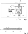
- Figs. 9 and 10 show an embodiment where primary incoupler 14 and/or primary outcoupler 16 is/are arranged at windows 52, 54 of the document.
- These windows 52, 54 are designed to be transparent for at least one wavelength that is coupled in/out by primary incoupler 14 and primary outcoupler 16, respectively.
- transparent advantageously designates that at least 25%, in particular at least 50%, in particular at least 75%, of the light at said wavelength are transmitted through carrier 10 at the location of the window, advantageously without being scattered.
- first window 52 being located at primary incoupler 14 and second window 54 being located at primary outcoupler 16.
- Protective area 18 again may cover at least part of personalized area 20, such as e.g. photograph 36 as shown.
- the identification document may comprise further document-specific information outside personalized area 20.
- a unique number of the identification document such as a passport number, may be arranged outside personalized area 20.
- Even some personalized information may be arranged outside personalized area 20, in which case the lightguide only protects the personalized information it covers at least partially.
- personalized area 20 at least includes any photograph 26 of the owner and at least one instance of the name data 22a, 22b of the owner, and preferably also any data carrier 28 with owner-specific information.
- primary incoupler 14 advantageously spreads the light it couples into lightguide 12.
- it is structured to generate a fan of light in lightguide 10 that has an angular width of at least 20°, advantageously at least 30°.
- the width of the fan is defined by the angular range over which the guided light varies within 50% of the maximum intensity.
- Such light fanning can e.g. be achieved by structuring primary incoupler 14 as a curved diffraction grating 46 as illustrated (not to scale) in Fig. 1 . It can also be achieved by selecting a coupler having a broad acceptance angle and a non-collimated light source such as a LED, for example the LED flash of a smartphone back-camera.
- a coupler having a broad acceptance angle and a non-collimated light source such as a LED, for example the LED flash of a smartphone back-camera.
- primary incoupler 14 advantageously spreads the light it couples into lightguide 12 to illuminate all of the extension W of primary outcoupler 16 (which is e.g. the extension along direction Y in Fig. 1 ) with a variation of intensity of 50% or less over the whole extension W.
- protective area 18 covers all of the writing for name data 22a, 22b, the writing 24 for date of birth, and the data carrier 28. However, it only covers part of photograph 26.
- protective area 18 advantageously overlaps with all or at least 50%, in particular at least 75% of every personalized information in personalized area 20. For example, it may cover photograph 26 fully and/or any other personalized information only partially.
- Primary incoupler 14 and/or primary outcoupler 16 may be adapted to respectively in/out couple light from/to below document, provided the carrier 10 is at least partially transparent in the area where the primary outcoupler and/or primary outcoupler is located.
- the observation of the outcoupled light can be designed to be on the illumination side or on the opposite side with respect to the illumination side with respect to the document of identification.
- the outcoupler can be made of a fluorescent region, preferably a fluorescent region that is non-homogeneous in color or design.
- the fluorescent outcoupler material is designed to have low absorption in the visible range if located in the personalized area, so that it does not obstruct the reading of the personalized area when no light is shined on the primary incoupler 14, i.e. into the lightguide.
- the primary outcoupler structure 16 may represent at least part of the portrait of the owner of the identification document.
- outcoupler structure 16 is personalized to the user, which makes the security feature even harder to fake and easier to verify.
- This can be realized by additive processes, subtractive processes, material modification processes, such as laser irradiation, or by printing a material onto the lightguide that scatters the guided light or fluorescent material that is excited to fluorescence by the guided light.
- a fluorescent portrait of the owner of the identification document may be printed such as it become visible when illumination light is shined on the primary incoupler 14.
- the lightguide may contain several incouplers arranged to couple light into the lightguide and towards the protective area with different main propagation direction or with different spectral composition, i.e. color.
- the primary incoupler 14 may be elongated macroscopically and substantially parallel to one edge of the protective area to provide multiple illumination axes into the lightguide or an easier incoupler to light-source alignment.
- neither primary incoupler 14 nor primary outcoupler 16 are completely arranged within the personalized area 20.
- Fig. 8 in contrast thereto, shows an embodiment where with primary incoupler 14 and primary outcoupler 16 are arranged completely within personalized area 20.
- only one of them i.e. only the incoupler or the outcoupler
- Protective area 18 may comprise at least one further visual security element, in addition to the outcoupler structures.
- a security element 50 is shown, by way of example, as a dotted cross in Fig. 1 .
- This further security document is visible in reflection, i.e. by shining light onto the lightguide without coupling it into the lightguide. It renders it difficult to place e.g. a false photograph or another counterfeiting element on top of the lightguide without being detected.
- a further security element may be controlled in transmission.
- Such a further visual security element may e.g. be at least one of an optically variable device, such as a diffractive structure, and non-variable markings, such as printed markings.
- Lightguide 10 may be a foil manufactured apart from carrier 10 and then laminated thereto, or it may also be formed in-situ on carrier 10.
- any incoupler and/or outcoupler mentioned herein may e.g. be a diffractive incoupler/outcoupler, a fluorescent incoupler/outcoupler, an Infrared Up-converting incoupler/outcoupler, an incoupler/outcoupler based on microscopic surface structures (i.e. surface structures without diffractive effects, such as microlenses or micro mirrors or surface structures having a lateral repetition period (i.e. a repetition period within the plane of the lightguide) of e.g. at least 10 ⁇ m), diffusing or scattering structures or materials.
- microscopic surface structures i.e. surface structures without diffractive effects, such as microlenses or micro mirrors or surface structures having a lateral repetition period (i.e. a repetition period within the plane of the lightguide) of e.g. at least 10 ⁇ m
- a lateral repetition period i.e. a repetition period within the plane of the lightguide
- the primary incoupler may also be placed e.g. between two ends of the lightguide, e.g. with two protective areas on different, in particular opposite, sides of it.
- lightguide 12 may (for any embodiments) be strip-shaped, with a length much larger, in particular at least five times larger, than its width, and advantageously with a constant width along its whole length. It may extend across the whole document, i.e. from one of its edges to the opposite edge.
Landscapes
- Physics & Mathematics (AREA)
- General Physics & Mathematics (AREA)
- Optics & Photonics (AREA)
- Credit Cards Or The Like (AREA)
- Optical Integrated Circuits (AREA)
Claims (25)
- Ein Ausweisdokument umfassendeinen personalisierten Bereich (20), welcher personalisierte Informationen (22 - 28) trägt, die einen Besitzer des Dokuments identifizieren, undeinen optischen Lichtleiter (12) mit einem primären Einkoppler (14) und einem primären Auskoppler (16),wobei der Lichtleiter (12) einen Schutzbereich (18) zwischen dem primären Einkoppler (14) und dem primären Auskoppler (16) bildet, wobei der Schutzbereich (18) zumindest einen Teil des personalisierten Bereichs (20) überlappt,dadurch gekennzeichnet, dass der primäre Einkoppler (14) seitlich an einer ersten Seite des personalisierten Bereichs (20) angeordnet ist.
- Das Dokument nach Anspruch 1, wobei der Lichtleiter (12) unterhalb des personalisierten Bereichs (20) angeordnet ist.
- Das Dokument nach Anspruch 1, wobei der Lichtleiter (12) oberhalb des personalisierten Bereichs (20) angeordnet ist.
- Das Dokument nach einem der vorhergehenden Ansprüche, wobei sich der Lichtleiter (12) vollständig über den personalisierten Bereich (20) erstreckt.
- Das Dokument nach einem der vorhergehenden Ansprüche, wobei der primäre Einkoppler (14) entweder- seitlich ausserhalb einer ersten Kante (34) des personalisierten Bereichs (20) angeordnet ist, oder- überlappend mit der ersten Kante (34) des personalisierten Bereichs (20) angeordnet ist,wobei die erste Kante (34) eine Kante des personalisierten Bereichs (20) auf der ersten Seite ist.
- Das Dokument nach einem der vorangehenden Ansprüche, wobei der primäre Auskoppler (16) seitlich an einer zweiten Seite des personalisierten Bereichs (20) angeordnet ist.
- Das Dokument nach Anspruch 6, wobei der primäre Auskoppler (16) entweder- seitlich außerhalb einer zweiten Kante (36) des personalisierten Bereichs (20) angeordnet ist, oder- überlappend mit der zweiten Kante (36) des personalisierten Bereichs (20) angeordnet ist,wobei die zweite Kante (36) eine Kante des personalisierten Bereichs (20) auf der zweiten Seite ist.
- Das Dokument nach einem der Ansprüche 4 oder 5 und nach einem der Ansprüche 6 oder 7, wobei sich die erste Seite von der zweiten Seite unterscheidet, und insbesondere, wobei die erste Seite der zweiten Seite gegenüberliegt.
- Das Dokument nach einem der vorhergehenden Ansprüche, wobei der primäre Einkoppler (14) und/oder der primäre Auskoppler (16) nicht mehr als 20 %, insbesondere nicht mehr als 10 %, des personalisierten Bereichs (20) überlappen.
- Das Dokument nach einem der vorangehenden Ansprüche, wobei der primäre Einkoppler (14) und/oder der primäre Auskoppler (16) den personalisierten Bereich (20) nicht überlappt/überlappen.
- Das Dokument nach einem der vorhergehenden Ansprüche, wobei der Lichtleiter (12) in dem Schutzbereich (18) und/oder dem personalisierten Bereich (20) keine Einkopplungs- und/oder keine Auskopplungsstrukturen aufweist.
- Das Dokument nach einem der vorhergehenden Ansprüche, wobei der Lichtleiter (12) eine sekundäre Auskoppelstruktur (40) in dem Schutzbereich (18) aufweist, wobei- die sekundäre Auskopplungsstruktur (40) nicht mehr als 20 %,
insbesondere nicht mehr als 10 %, des Schutzbereichs (18) bedeckt und- für jeden Punkt (P) in dem genannten Schutzbereich (18) eine kürzeste Entfernung (d) zu dem sekundären Auskoppler (40) kleiner als L/3 ist, wobei L eine Ausdehnung des Schutzbereichs (18) in einer Richtung (X) zwischen dem primären Einkoppler (14) und dem primären Auskoppler (16) ist. - Das Dokument nach Anspruch 12, wobei der sekundäre Auskoppler (16) mindestens ein linienförmiges Auskoppelelement (42) in dem Schutzbereich (18) aufweist, wobei der linienförmige primäre Auskoppler (16) eine Länge (v) von mindestens 5 mm, insbesondere von mindestens 10 mm, aufweist und eine Breite (w) von nicht mehr als 1 mm, insbesondere von nicht mehr als 0,5 mm, insbesondere von nicht mehr als 0,2 mm.
- Das Dokument nach einem der vorhergehenden Ansprüche, wobei eine Überlappung zwischen der personalisierten Information (22 - 28) in dem Schutzbereich (18) und dem personalisierten Bereich (20) mindestens 1 cm2 beträgt, insbesondere mindestens 2 cm2.
- Das Dokument nach einem der vorhergehenden Ansprüche, wobei der Schutzbereich (18) in einer Richtung (X) zwischen dem primären Einkoppler (14) und dem primären Auskoppler (16) eine Ausdehnung (L) von mindestens 1 cm, insbesondere von mindestens 2 cm, aufweist.
- Das Dokument nach einem der vorhergehenden Ansprüche, wobei der Schutzbereich (18) in dem personalisierten Bereich (20) mit mindestens einem der folgenden Informationsträger (22-28) überlappt:- Schriftzug (22a, 22b), welcher Namensdaten eines Besitzers des Dokuments repräsentiert,- Schriftzug (24) mit Geburtsdatum und/oder Geburtsort des Besitzers des Dokuments- eine Fotografie (26) des Besitzers des Dokuments, und/oder- ein elektronischer Datenträger (28), welcher Identifikationsdaten des Besitzers trägt.
- Das Dokument nach Anspruch 16, wobei der Schutzbereich (18) mit mehreren der Informationsträger (22 - 28) überlappt.
- Das Dokument nach einem der Ansprüche 16 oder 17, wobei die Schutzbereich (18) mindestens einen dieser Informationsträger (22 - 28) vollständig überlappt.
- Das Dokument nach einem der vorhergehenden Ansprüche mit einem ersten Lichtleiter (12a), der oberhalb des personalisierten Bereichs (20) angeordnet ist, und einem zweiten Lichtleiter (12b), der unterhalb des personalisierten Bereichs (20) angeordnet ist.
- Das Dokument nach Anspruch 19, wobei sich die primären Einkoppler (14a, 14b) des ersten und des zweiten Lichtleiters (12a, 12b) überlappen.
- Das Dokument nach einem der Ansprüche 19 oder 20, wobei die primären Auskoppler (16a, 16b) des ersten und zweiten Lichtleiters (12a, 12b) einen nicht überlappenden Bereich aufweisen.
- Das Dokument nach einem der Ansprüche 19 bis 21, wobei die primären Auskoppler (16a, 16b) des ersten und zweiten Lichtleiters (12a, 12b) komplementäre Formen aufweisen.
- Das Dokument nach einem der vorhergehenden Ansprüche, wobei der primäre Einkoppler (14) und/oder der primäre Auskoppler (16) vollständig innerhalb des personalisierten Bereichs (20) angeordnet ist.
- Das Dokument nach einem der vorhergehenden Ansprüche umfassend ein weiteres Sicherheitselement (50), zusätzlich zu dem Einkoppler und dem Auskoppler (14, 16), welches in Reflexion oder in Transmission sichtbar ist, und insbesondere, wobei das weitere Sicherheitselement (50) mindestens eines von einer optisch variablen Vorrichtung, wie einer diffraktiven Struktur, und nicht variablen Markierungen, wie gedruckten Markierungen, ist.
- Das Dokument nach einem der vorhergehenden Ansprüche umfassend mindestens ein Fenster (52, 54), welches sich an einer Stelle des primären Einkopplers (14) und/oder des primären Auskopplers (16) befindet.
Applications Claiming Priority (1)
| Application Number | Priority Date | Filing Date | Title |
|---|---|---|---|
| PCT/EP2020/051881 WO2021151460A1 (en) | 2020-01-27 | 2020-01-27 | Document of identification with optical lightguide |
Publications (2)
| Publication Number | Publication Date |
|---|---|
| EP4054852A1 EP4054852A1 (de) | 2022-09-14 |
| EP4054852B1 true EP4054852B1 (de) | 2025-01-15 |
Family
ID=69400538
Family Applications (1)
| Application Number | Title | Priority Date | Filing Date |
|---|---|---|---|
| EP20702757.4A Active EP4054852B1 (de) | 2020-01-27 | 2020-01-27 | Identifikationsdokument mit optischem lichtleiter |
Country Status (6)
| Country | Link |
|---|---|
| US (1) | US20220371355A1 (de) |
| EP (1) | EP4054852B1 (de) |
| JP (1) | JP7587588B2 (de) |
| CN (1) | CN115003513A (de) |
| IL (1) | IL295092A (de) |
| WO (1) | WO2021151460A1 (de) |
Families Citing this family (2)
| Publication number | Priority date | Publication date | Assignee | Title |
|---|---|---|---|---|
| WO2019198849A1 (ko) * | 2018-04-13 | 2019-10-17 | 주식회사 로드시스템 | 모바일 여권 및 이를 생성하기 위한 모바일 여권 생성시스템과 모바일 여권 인증 방법 |
| WO2025056167A1 (en) | 2023-09-14 | 2025-03-20 | Orell Füssli AG | Light-guide-based protective optical element for security documents and a security document |
Family Cites Families (20)
| Publication number | Priority date | Publication date | Assignee | Title |
|---|---|---|---|---|
| US4593936A (en) * | 1984-03-06 | 1986-06-10 | Opel George E | Universal credit card |
| DE3835999C2 (de) | 1988-10-21 | 2001-05-10 | Gao Ges Automation Org | Verfahren und Vorrichtung zum Herstellen eines Identifikationsdokuments in Buchform |
| DE69739712D1 (de) | 1996-09-19 | 2010-02-04 | Dainippon Printing Co Ltd | Mehrschichtiges volumenhologramm und etikett zur herstellung eines mehrschichtigen volumenhologramms |
| DE10008851A1 (de) * | 2000-02-25 | 2001-08-30 | Giesecke & Devrient Gmbh | Verfahren zur Herstellung laserbeschriftbarer Datenträger und damit hergestellte Datenträger |
| DE102004039567A1 (de) * | 2004-08-13 | 2006-02-23 | Ovd Kinegram Ag | Individualisiertes Sicherheitsdokument |
| DE102005052326A1 (de) * | 2005-11-02 | 2007-05-03 | Giesecke & Devrient Gmbh | Sicherheitselement und Verfahren zu seiner Herstellung |
| JP4882397B2 (ja) * | 2006-02-01 | 2012-02-22 | 凸版印刷株式会社 | 表示体、及び表示装置 |
| PL2512742T3 (pl) | 2009-12-18 | 2014-08-29 | Orell Fuessli Sicherheitsdruck Ag | Dokument bezpieczeństwa z falowodem optycznym |
| AT509928A2 (de) | 2010-05-26 | 2011-12-15 | Hueck Folien Gmbh | Sicherheitselement mit lichtleiterstrukturen |
| RU2546510C2 (ru) | 2010-07-07 | 2015-04-10 | Орелл Фюссли Зихерхайтсдрук Аг | Защищенный документ с голографической пленкой и печатной машиночитаемой маркировкой |
| US20140355298A1 (en) * | 2013-05-31 | 2014-12-04 | 3M Innovative Properties Company | Adhesive lightguide with resonant circuit |
| WO2015036045A1 (en) * | 2013-09-13 | 2015-03-19 | CSEM Centre Suisse d'Electronique et de Microtechnique SA - Recherche et Développement | Lightguide tamper seal |
| WO2017148704A1 (de) * | 2016-03-02 | 2017-09-08 | Ovd Kinegram Ag | Sicherheitsdokument und verfahren zu dessen authentifizierung |
| WO2017217428A1 (ja) | 2016-06-13 | 2017-12-21 | 大日本印刷株式会社 | 導光フィルム、偽造防止用構造体及び偽造防止物品 |
| JP7095678B2 (ja) * | 2017-03-03 | 2022-07-05 | 大日本印刷株式会社 | 導光体、偽造防止物品 |
| US20200019740A1 (en) * | 2017-03-06 | 2020-01-16 | Orell Füssli Sicherheitsdruck Ag | An owner-controlled carrier of value, a payment infrastructure and method for operating this infrastructure |
| WO2018161180A1 (en) * | 2017-03-06 | 2018-09-13 | Orell Füssli Sicherheitsdruck Ag | A carrier of value having a display and improved tampering resistance |
| JP7159606B2 (ja) | 2018-05-08 | 2022-10-25 | 凸版印刷株式会社 | 感熱転写媒体および情報記録体 |
| EP3880487B1 (de) * | 2018-11-16 | 2023-05-31 | Orell Füssli AG | Wellenleiter basierte fälschungssichere sicherheitsvorrichtung |
| WO2021151459A1 (en) * | 2020-01-27 | 2021-08-05 | Orell Füssli AG | Security document with lightguide having a sparse outcoupler structure |
-
2020
- 2020-01-27 EP EP20702757.4A patent/EP4054852B1/de active Active
- 2020-01-27 IL IL295092A patent/IL295092A/en unknown
- 2020-01-27 US US17/795,194 patent/US20220371355A1/en not_active Abandoned
- 2020-01-27 CN CN202080094412.XA patent/CN115003513A/zh active Pending
- 2020-01-27 WO PCT/EP2020/051881 patent/WO2021151460A1/en not_active Ceased
- 2020-01-27 JP JP2022544743A patent/JP7587588B2/ja active Active
Also Published As
| Publication number | Publication date |
|---|---|
| JP7587588B2 (ja) | 2024-11-20 |
| EP4054852A1 (de) | 2022-09-14 |
| US20220371355A1 (en) | 2022-11-24 |
| IL295092A (en) | 2022-09-01 |
| WO2021151460A1 (en) | 2021-08-05 |
| CN115003513A (zh) | 2022-09-02 |
| JP2023511930A (ja) | 2023-03-23 |
Similar Documents
| Publication | Publication Date | Title |
|---|---|---|
| KR102488710B1 (ko) | 적층체, 신분증명서, 및, 신분증명서의 검증 방법 | |
| EP2129532B1 (de) | Sicheres ausweisdokument und herstellungsverfahren dafür | |
| EP2373493B1 (de) | Identifikationsdokument mit einem verbesserten fälschungsschutzelement | |
| CN103228458B (zh) | 有全息箔及印刷的机器可读标记的安全文件 | |
| EP2901183B1 (de) | Mit einer sicherheitsfunktion geformter lichtsteuerungsfilm | |
| US9221246B2 (en) | Method for printing an image onto a thermoplastic substrate, pre-forming plate used therefor and security instrument made therefrom | |
| JP4728335B2 (ja) | 偽造防止セキュリティオブジェクト | |
| EP4054855B1 (de) | Sicherheitsdokument mit lichtleiter mit spärlicher auskopplerstruktur | |
| US20220371355A1 (en) | Document of identification with optical lightguide | |
| US12043054B2 (en) | Display | |
| KR102244285B1 (ko) | 화상 표시 디바이스 및, 화상 표시 매체 | |
| US20090121473A1 (en) | Optical Structure, in Particular for a Security Document and/or a Document of Value | |
| EP3571062B1 (de) | Sicherheitsdokument mit einem fenster und einer brechungsstruktur | |
| KR101682015B1 (ko) | 시야각 제한 보안 필름 | |
| US20100060989A1 (en) | security document with micro-prisms | |
| EP4729303A1 (de) | Laminierte mikrooptische strukturen | |
| EP2177368A1 (de) | Identifizierungsdokument mit farbigem, persönlichem Innenleben | |
| JP7011796B2 (ja) | 光学素子、印刷物および偽造防止媒体 | |
| KR100781740B1 (ko) | 유가증권의 위조방지방법 |
Legal Events
| Date | Code | Title | Description |
|---|---|---|---|
| STAA | Information on the status of an ep patent application or granted ep patent |
Free format text: STATUS: UNKNOWN |
|
| STAA | Information on the status of an ep patent application or granted ep patent |
Free format text: STATUS: THE INTERNATIONAL PUBLICATION HAS BEEN MADE |
|
| PUAI | Public reference made under article 153(3) epc to a published international application that has entered the european phase |
Free format text: ORIGINAL CODE: 0009012 |
|
| STAA | Information on the status of an ep patent application or granted ep patent |
Free format text: STATUS: REQUEST FOR EXAMINATION WAS MADE |
|
| 17P | Request for examination filed |
Effective date: 20220607 |
|
| AK | Designated contracting states |
Kind code of ref document: A1 Designated state(s): AL AT BE BG CH CY CZ DE DK EE ES FI FR GB GR HR HU IE IS IT LI LT LU LV MC MK MT NL NO PL PT RO RS SE SI SK SM TR |
|
| DAV | Request for validation of the european patent (deleted) | ||
| DAX | Request for extension of the european patent (deleted) | ||
| GRAP | Despatch of communication of intention to grant a patent |
Free format text: ORIGINAL CODE: EPIDOSNIGR1 |
|
| STAA | Information on the status of an ep patent application or granted ep patent |
Free format text: STATUS: GRANT OF PATENT IS INTENDED |
|
| INTG | Intention to grant announced |
Effective date: 20240910 |
|
| GRAS | Grant fee paid |
Free format text: ORIGINAL CODE: EPIDOSNIGR3 |
|
| GRAA | (expected) grant |
Free format text: ORIGINAL CODE: 0009210 |
|
| STAA | Information on the status of an ep patent application or granted ep patent |
Free format text: STATUS: THE PATENT HAS BEEN GRANTED |
|
| AK | Designated contracting states |
Kind code of ref document: B1 Designated state(s): AL AT BE BG CH CY CZ DE DK EE ES FI FR GB GR HR HU IE IS IT LI LT LU LV MC MK MT NL NO PL PT RO RS SE SI SK SM TR |
|
| REG | Reference to a national code |
Ref country code: CH Ref legal event code: EP Ref country code: GB Ref legal event code: FG4D |
|
| REG | Reference to a national code |
Ref country code: DE Ref legal event code: R096 Ref document number: 602020044752 Country of ref document: DE |
|
| REG | Reference to a national code |
Ref country code: IE Ref legal event code: FG4D |
|
| REG | Reference to a national code |
Ref country code: NL Ref legal event code: MP Effective date: 20250115 |
|
| PG25 | Lapsed in a contracting state [announced via postgrant information from national office to epo] |
Ref country code: NL Free format text: LAPSE BECAUSE OF FAILURE TO SUBMIT A TRANSLATION OF THE DESCRIPTION OR TO PAY THE FEE WITHIN THE PRESCRIBED TIME-LIMIT Effective date: 20250115 |
|
| PG25 | Lapsed in a contracting state [announced via postgrant information from national office to epo] |
Ref country code: RS Free format text: LAPSE BECAUSE OF FAILURE TO SUBMIT A TRANSLATION OF THE DESCRIPTION OR TO PAY THE FEE WITHIN THE PRESCRIBED TIME-LIMIT Effective date: 20250415 |
|
| PG25 | Lapsed in a contracting state [announced via postgrant information from national office to epo] |
Ref country code: FI Free format text: LAPSE BECAUSE OF FAILURE TO SUBMIT A TRANSLATION OF THE DESCRIPTION OR TO PAY THE FEE WITHIN THE PRESCRIBED TIME-LIMIT Effective date: 20250115 |
|
| PG25 | Lapsed in a contracting state [announced via postgrant information from national office to epo] |
Ref country code: PL Free format text: LAPSE BECAUSE OF FAILURE TO SUBMIT A TRANSLATION OF THE DESCRIPTION OR TO PAY THE FEE WITHIN THE PRESCRIBED TIME-LIMIT Effective date: 20250115 |
|
| PG25 | Lapsed in a contracting state [announced via postgrant information from national office to epo] |
Ref country code: ES Free format text: LAPSE BECAUSE OF FAILURE TO SUBMIT A TRANSLATION OF THE DESCRIPTION OR TO PAY THE FEE WITHIN THE PRESCRIBED TIME-LIMIT Effective date: 20250115 |
|
| REG | Reference to a national code |
Ref country code: LT Ref legal event code: MG9D |
|
| PG25 | Lapsed in a contracting state [announced via postgrant information from national office to epo] |
Ref country code: IS Free format text: LAPSE BECAUSE OF FAILURE TO SUBMIT A TRANSLATION OF THE DESCRIPTION OR TO PAY THE FEE WITHIN THE PRESCRIBED TIME-LIMIT Effective date: 20250515 Ref country code: NO Free format text: LAPSE BECAUSE OF FAILURE TO SUBMIT A TRANSLATION OF THE DESCRIPTION OR TO PAY THE FEE WITHIN THE PRESCRIBED TIME-LIMIT Effective date: 20250415 |
|
| REG | Reference to a national code |
Ref country code: AT Ref legal event code: MK05 Ref document number: 1759630 Country of ref document: AT Kind code of ref document: T Effective date: 20250115 |
|
| PG25 | Lapsed in a contracting state [announced via postgrant information from national office to epo] |
Ref country code: HR Free format text: LAPSE BECAUSE OF FAILURE TO SUBMIT A TRANSLATION OF THE DESCRIPTION OR TO PAY THE FEE WITHIN THE PRESCRIBED TIME-LIMIT Effective date: 20250115 |
|
| PG25 | Lapsed in a contracting state [announced via postgrant information from national office to epo] |
Ref country code: LV Free format text: LAPSE BECAUSE OF FAILURE TO SUBMIT A TRANSLATION OF THE DESCRIPTION OR TO PAY THE FEE WITHIN THE PRESCRIBED TIME-LIMIT Effective date: 20250115 Ref country code: PT Free format text: LAPSE BECAUSE OF FAILURE TO SUBMIT A TRANSLATION OF THE DESCRIPTION OR TO PAY THE FEE WITHIN THE PRESCRIBED TIME-LIMIT Effective date: 20250515 |
|
| PG25 | Lapsed in a contracting state [announced via postgrant information from national office to epo] |
Ref country code: GR Free format text: LAPSE BECAUSE OF FAILURE TO SUBMIT A TRANSLATION OF THE DESCRIPTION OR TO PAY THE FEE WITHIN THE PRESCRIBED TIME-LIMIT Effective date: 20250416 Ref country code: BG Free format text: LAPSE BECAUSE OF FAILURE TO SUBMIT A TRANSLATION OF THE DESCRIPTION OR TO PAY THE FEE WITHIN THE PRESCRIBED TIME-LIMIT Effective date: 20250115 |
|
| PG25 | Lapsed in a contracting state [announced via postgrant information from national office to epo] |
Ref country code: AT Free format text: LAPSE BECAUSE OF FAILURE TO SUBMIT A TRANSLATION OF THE DESCRIPTION OR TO PAY THE FEE WITHIN THE PRESCRIBED TIME-LIMIT Effective date: 20250115 |
|
| PG25 | Lapsed in a contracting state [announced via postgrant information from national office to epo] |
Ref country code: SE Free format text: LAPSE BECAUSE OF FAILURE TO SUBMIT A TRANSLATION OF THE DESCRIPTION OR TO PAY THE FEE WITHIN THE PRESCRIBED TIME-LIMIT Effective date: 20250115 |
|
| PG25 | Lapsed in a contracting state [announced via postgrant information from national office to epo] |
Ref country code: LU Free format text: LAPSE BECAUSE OF NON-PAYMENT OF DUE FEES Effective date: 20250127 |
|
| PG25 | Lapsed in a contracting state [announced via postgrant information from national office to epo] |
Ref country code: SM Free format text: LAPSE BECAUSE OF FAILURE TO SUBMIT A TRANSLATION OF THE DESCRIPTION OR TO PAY THE FEE WITHIN THE PRESCRIBED TIME-LIMIT Effective date: 20250115 |
|
| PG25 | Lapsed in a contracting state [announced via postgrant information from national office to epo] |
Ref country code: DK Free format text: LAPSE BECAUSE OF FAILURE TO SUBMIT A TRANSLATION OF THE DESCRIPTION OR TO PAY THE FEE WITHIN THE PRESCRIBED TIME-LIMIT Effective date: 20250115 |
|
| PG25 | Lapsed in a contracting state [announced via postgrant information from national office to epo] |
Ref country code: MC Free format text: LAPSE BECAUSE OF FAILURE TO SUBMIT A TRANSLATION OF THE DESCRIPTION OR TO PAY THE FEE WITHIN THE PRESCRIBED TIME-LIMIT Effective date: 20250115 |
|
| PG25 | Lapsed in a contracting state [announced via postgrant information from national office to epo] |
Ref country code: IT Free format text: LAPSE BECAUSE OF FAILURE TO SUBMIT A TRANSLATION OF THE DESCRIPTION OR TO PAY THE FEE WITHIN THE PRESCRIBED TIME-LIMIT Effective date: 20250115 |
|
| PG25 | Lapsed in a contracting state [announced via postgrant information from national office to epo] |
Ref country code: BE Free format text: LAPSE BECAUSE OF NON-PAYMENT OF DUE FEES Effective date: 20250131 |
|
| REG | Reference to a national code |
Ref country code: DE Ref legal event code: R097 Ref document number: 602020044752 Country of ref document: DE |
|
| PG25 | Lapsed in a contracting state [announced via postgrant information from national office to epo] |
Ref country code: CZ Free format text: LAPSE BECAUSE OF FAILURE TO SUBMIT A TRANSLATION OF THE DESCRIPTION OR TO PAY THE FEE WITHIN THE PRESCRIBED TIME-LIMIT Effective date: 20250115 Ref country code: EE Free format text: LAPSE BECAUSE OF FAILURE TO SUBMIT A TRANSLATION OF THE DESCRIPTION OR TO PAY THE FEE WITHIN THE PRESCRIBED TIME-LIMIT Effective date: 20250115 |
|
| REG | Reference to a national code |
Ref country code: BE Ref legal event code: MM Effective date: 20250131 |
|
| PG25 | Lapsed in a contracting state [announced via postgrant information from national office to epo] |
Ref country code: RO Free format text: LAPSE BECAUSE OF FAILURE TO SUBMIT A TRANSLATION OF THE DESCRIPTION OR TO PAY THE FEE WITHIN THE PRESCRIBED TIME-LIMIT Effective date: 20250115 |
|
| PG25 | Lapsed in a contracting state [announced via postgrant information from national office to epo] |
Ref country code: SK Free format text: LAPSE BECAUSE OF FAILURE TO SUBMIT A TRANSLATION OF THE DESCRIPTION OR TO PAY THE FEE WITHIN THE PRESCRIBED TIME-LIMIT Effective date: 20250115 |
|
| PLBE | No opposition filed within time limit |
Free format text: ORIGINAL CODE: 0009261 |
|
| STAA | Information on the status of an ep patent application or granted ep patent |
Free format text: STATUS: NO OPPOSITION FILED WITHIN TIME LIMIT |
|
| REG | Reference to a national code |
Ref country code: CH Ref legal event code: L10 Free format text: ST27 STATUS EVENT CODE: U-0-0-L10-L00 (AS PROVIDED BY THE NATIONAL OFFICE) Effective date: 20251126 |
|
| 26N | No opposition filed |
Effective date: 20251016 |
|
| GBPC | Gb: european patent ceased through non-payment of renewal fee |
Effective date: 20250415 |
|
| PG25 | Lapsed in a contracting state [announced via postgrant information from national office to epo] |
Ref country code: GB Free format text: LAPSE BECAUSE OF NON-PAYMENT OF DUE FEES Effective date: 20250415 |
|
| PG25 | Lapsed in a contracting state [announced via postgrant information from national office to epo] |
Ref country code: IE Free format text: LAPSE BECAUSE OF NON-PAYMENT OF DUE FEES Effective date: 20250127 |
|
| REG | Reference to a national code |
Ref country code: CH Ref legal event code: U11 Free format text: ST27 STATUS EVENT CODE: U-0-0-U10-U11 (AS PROVIDED BY THE NATIONAL OFFICE) Effective date: 20260201 |
|
| PGFP | Annual fee paid to national office [announced via postgrant information from national office to epo] |
Ref country code: DE Payment date: 20260121 Year of fee payment: 7 |
|
| PGFP | Annual fee paid to national office [announced via postgrant information from national office to epo] |
Ref country code: FR Payment date: 20260123 Year of fee payment: 7 |
|
| PGFP | Annual fee paid to national office [announced via postgrant information from national office to epo] |
Ref country code: CH Payment date: 20260201 Year of fee payment: 7 |