EP4053973B1 - Module accumulateur d'énergie - Google Patents
Module accumulateur d'énergie Download PDFInfo
- Publication number
- EP4053973B1 EP4053973B1 EP22158568.0A EP22158568A EP4053973B1 EP 4053973 B1 EP4053973 B1 EP 4053973B1 EP 22158568 A EP22158568 A EP 22158568A EP 4053973 B1 EP4053973 B1 EP 4053973B1
- Authority
- EP
- European Patent Office
- Prior art keywords
- side wall
- energy storage
- conductive material
- storage module
- housing
- Prior art date
- Legal status (The legal status is an assumption and is not a legal conclusion. Google has not performed a legal analysis and makes no representation as to the accuracy of the status listed.)
- Active
Links
Images



Classifications
-
- H—ELECTRICITY
- H01—ELECTRIC ELEMENTS
- H01M—PROCESSES OR MEANS, e.g. BATTERIES, FOR THE DIRECT CONVERSION OF CHEMICAL ENERGY INTO ELECTRICAL ENERGY
- H01M10/00—Secondary cells; Manufacture thereof
- H01M10/60—Heating or cooling; Temperature control
- H01M10/65—Means for temperature control structurally associated with the cells
- H01M10/655—Solid structures for heat exchange or heat conduction
- H01M10/6551—Surfaces specially adapted for heat dissipation or radiation, e.g. fins or coatings
-
- Y—GENERAL TAGGING OF NEW TECHNOLOGICAL DEVELOPMENTS; GENERAL TAGGING OF CROSS-SECTIONAL TECHNOLOGIES SPANNING OVER SEVERAL SECTIONS OF THE IPC; TECHNICAL SUBJECTS COVERED BY FORMER USPC CROSS-REFERENCE ART COLLECTIONS [XRACs] AND DIGESTS
- Y02—TECHNOLOGIES OR APPLICATIONS FOR MITIGATION OR ADAPTATION AGAINST CLIMATE CHANGE
- Y02E—REDUCTION OF GREENHOUSE GAS [GHG] EMISSIONS, RELATED TO ENERGY GENERATION, TRANSMISSION OR DISTRIBUTION
- Y02E60/00—Enabling technologies; Technologies with a potential or indirect contribution to GHG emissions mitigation
- Y02E60/10—Energy storage using batteries
-
- Y—GENERAL TAGGING OF NEW TECHNOLOGICAL DEVELOPMENTS; GENERAL TAGGING OF CROSS-SECTIONAL TECHNOLOGIES SPANNING OVER SEVERAL SECTIONS OF THE IPC; TECHNICAL SUBJECTS COVERED BY FORMER USPC CROSS-REFERENCE ART COLLECTIONS [XRACs] AND DIGESTS
- Y02—TECHNOLOGIES OR APPLICATIONS FOR MITIGATION OR ADAPTATION AGAINST CLIMATE CHANGE
- Y02E—REDUCTION OF GREENHOUSE GAS [GHG] EMISSIONS, RELATED TO ENERGY GENERATION, TRANSMISSION OR DISTRIBUTION
- Y02E60/00—Enabling technologies; Technologies with a potential or indirect contribution to GHG emissions mitigation
- Y02E60/14—Thermal energy storage
Definitions
- the invention relates to an energy storage module with a cuboid-shaped housing and at least two storage cells arranged therein.
- document EN 10 2019 108386 A1 discloses a holding device for a battery of a motor vehicle, wherein the holding device has a receiving compartment for each of a plurality of prismatic cells, the boundary walls of which each have a wave-shaped cross-section along the vertical direction, increasing the stability of the holding device.
- document US 2020/006825 A1 a battery module for a vehicle, which is formed by a cooling channel module, side covers and a cover plate, wherein the cover plate has a wave-shaped cross-section.
- the invention is based on the object of specifying an energy storage module which ensures reliable heat dissipation to the surroundings of the housing and can easily prevent the energy storage module from overheating.
- This object is achieved by an energy storage module and a vehicle with at least one such energy storage module according to the features of the independent patent claims. Further developments are specified in the respective dependent patent claims.
- an energy storage module has at least one cuboid-shaped housing with four side walls and two end walls, in which at least two storage cells are arranged.
- at least two of the side walls of the housing are made of a thermally conductive material and each have at least one side wall region with a wavy cross-section on both the outside and the inside of the side wall, wherein the at least two side walls are made from one or more metal sheets, wherein the insides of at least the side wall regions are each covered or coated with an electrically insulating but thermally conductive material which rests on the inside without a gap, wherein the material is covered or coated on its side facing away from the side wall region with an electrically conductive material (310) which rests on the electrically insulating, thermally conductive material without a gap, wherein the side wall region), the electrically insulating, thermally conductive material and the electrically conductive material form a sandwich structure (320).
- An advantage of the energy storage module according to the invention is that the wave-shaped cross section of the side wall areas results in an increase in the surface area of the housing, which enables heat to be dissipated to the outside or to the ambient atmosphere of the housing without having to provide special cooling devices such as cooling fins or a separate cooling plate thermally connected to the housing.
- the cuboid-shaped housing has at least one side wall region with a wave-shaped cross-section on three or more cuboid partial surfaces or side walls.
- each elevation on the outside of the side wall region is opposite a corresponding depression on the inside of the side wall region, and each depression on the outside of the side wall region is opposite a corresponding elevation on the inside of the side wall region.
- the wall thickness in the side wall areas is constant.
- the wave-shaped cross section of the side wall regions has been formed by deformation of the thermally conductive material, in particular by means of a deep-drawing process.
- all four side walls and, if necessary, the end walls are made from one or more metal sheets, which are deep-drawn in whole or in sections.
- Suitable metal sheets include, for example, sheets made from aluminum or stainless steel.
- the at least two side walls are each flat on the edge and each have at least one side wall region in their inner region, wherein the side wall regions are each enclosed by a flat peripheral edge region of the side wall.
- the side walls are preferably each arranged at an angle to one or more adjacent side walls and end walls.
- Adjacent side walls can be formed by a common element, for example a common sheet metal, which is bent at one or more bending edges.
- the bending edges segment the common element into adjacent side walls of the housing.
- adjacent side walls can also be formed by separate housing parts, for example in the form of individual sheets, which have been placed at an angle to one another and connected to one another, preferably welded, screwed and/or riveted.
- housing is formed by separate housing parts, these are preferably connected to each other seamlessly or in a fluid-tight manner in order to form a hermetically sealed housing.
- Adjacent housing parts can be flat, folded, flanged or provided with a groove in the interface area or in the area of their contact edges.
- the side wall regions each have ribs and/or grooves or channels which extend parallel along a predetermined fluid flow direction.
- At least the inside of the side wall areas is covered or coated with an electrically insulating but thermally conductive material, which lies on the inside without a gap.
- the electrically insulating material preferably serves to electrically separate the storage cells from the housing.
- the material is covered or coated on its side facing away from the side wall region with an electrically conductive material which rests on the electrically insulating, thermally conductive material without a gap, wherein the side wall region, the electrically insulating, thermally conductive material and the electrically conductive material form a sandwich structure.
- the electrically conductive material or the inner lining formed thereby preferably has no electrical contact with the side wall of the housing or the outer housing wall.
- An inner lining or sandwich structure can advantageously prevent local temperature increases or so-called hotspots and thus lead to improved overall heat dissipation.
- At least one electrically insulating spacer for mechanically separating the at least one memory cell from the housing is arranged between at least one of the memory cells and the inner side of the side wall region, the electrically insulating, thermally conductive material or the electrically conductive material.
- Such a spacer can be provided as an alternative to covering the inside of a side wall area with an electrically insulating, thermally conductive material.
- fluid channels can be formed inside the housing by means of such spacers, which enable a fluid flow in the region of the inner sides of the housing.
- a circulation device is arranged in the housing, which serves to circulate a fluid inside the housing. This can advantageously achieve a homogeneous distribution of the heat emanating from the storage cells within the closed housing.
- a circulation device can be designed as a fan, for example, if air is circulated as the fluid in the housing.
- At least one of the end walls of the housing additionally has an end wall region with a wave-shaped cross-section on both the outside and the inside of the end wall, wherein the respective end wall region is designed in particular corresponding to a side wall region according to one or more of the above-described embodiments of the side wall regions.
- a vehicle according to the invention in particular a rail vehicle, has at least one energy storage module according to the invention.
- the vehicle further comprises a circulation device, in particular a fan, which is oriented such that a fluid flow generated by it is aligned along a longitudinal direction of ribs and/or grooves of the side wall regions.
- a circulation device in particular a fan, which is oriented such that a fluid flow generated by it is aligned along a longitudinal direction of ribs and/or grooves of the side wall regions.
- the ribs and/or grooves are aligned parallel to a longitudinal direction of the vehicle.
- At least one of the side walls or side wall regions may form a portion of the outer skin of the vehicle.
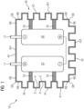
- the Figure 1 shows an embodiment of an energy storage module 10 according to the invention, which is equipped with two storage cells 20 and 30.
- the two storage cells 20 and 30 are in the embodiment according to Figure 1 electrically connected in series and are connected to external connection contacts or connection poles 11 and 12 of the energy storage module 10.
- the storage cells 20 and 30 can also be connected in parallel; additional storage cells can also be present, which can be connected in parallel or in series in any way.
- the storage cells 20, 30 are designed, for example, as lithium-ion cells.
- the storage cells 20 and 30 are accommodated in a common housing 40, the housing walls 41, 42, 43 and 44 of which surround or enclose the two storage cells 20 and 30.
- housing walls 41, 42, 43 of the housing 40 have housing wall regions 411, 421, 431 which enable heat to be dissipated to the surroundings of the housing 40 of the energy storage module 10 or to cool the storage cells 20, 30.
- a left side wall 41, a right side wall 42 as well as a lower end wall 43 and an upper end wall 44 are shown as examples.
- the wall areas 411 to 413 are flat in their respective outer area or in their respective edge area RB, but are wavy in their respective inner area for the purpose of increasing the surface area.
- Adjacent wall areas can be flat in the interface area SB as shown, alternatively they can be folded, flanged or provided with a groove.
- each elevation E on the outside A - relative to the respective edge region RB - of each of the side walls or end wall areas is opposite a corresponding depression V on the inside I.
- the respective wall thickness preferably remains constant, apart from manufacturing-related fluctuations.
- spacers 55 are provided, which preferably consist of electrically non-conductive but thermally conductive material.
- the spacers 55 can also be omitted if, for example, the storage cells 20 and 30 are to lie directly against a housing wall or be held by it.
- the side wall and end wall areas 411, 421 and 431 are shaped in such a way that, viewed from their respective edge area RB, they form outwardly projecting ribs 50, the longitudinal direction of which in the representation according to Figure 1 perpendicular to the image plane and forms a preferred direction for a fluid flow.
- the ribs 50 are preferably formed by material deformation, preferably by deep drawing, of the respective wall region 411, 421 or 431 It is advantageous if the wall areas 411, 421 and 431 are formed by deep-drawn sheets.
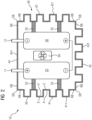
- the energy storage module 10 is additionally equipped with a circulation device 60, for example with a fan, which is arranged inside the housing 40 and circulates a fluid located inside the housing 40, for example air, another gas or an insulating liquid, in order to cool or heat the storage cells 20 and 30.
- a circulation device 60 for example with a fan, which is arranged inside the housing 40 and circulates a fluid located inside the housing 40, for example air, another gas or an insulating liquid, in order to cool or heat the storage cells 20 and 30.
- the Figure 3 shows a to the embodiment of the Figure 1 alternative embodiment of an energy storage module 10, in which the two side walls 41, 42 and the one end wall 43 are provided with grooves 70, viewed from the edge region RB of the respective wall.
- the longitudinal direction of the grooves 70 extends perpendicular to the image plane of the Figure 3 and forms a preferred fluid flow direction.
- the wall regions 411, 421 and 431 are formed by deep-drawn sheets.
- the Figure 4 shows a variant of the embodiment according to Figure 3 , in which a circulation device 60 is additionally arranged within the housing 40 of the energy storage module 10, which circulates a fluid located inside the housing 40 during operation of the energy storage module 10 and in particular during a charging or discharging process of the storage cells 20, 30 for the purpose of cooling or cooling the storage cells 20 and 30.
- a circulation device 60 is additionally arranged within the housing 40 of the energy storage module 10, which circulates a fluid located inside the housing 40 during operation of the energy storage module 10 and in particular during a charging or discharging process of the storage cells 20, 30 for the purpose of cooling or cooling the storage cells 20 and 30.
- the Figure 5 shows a further embodiment of an energy storage module 10 according to the invention, in a perspective view. From this illustration it is clear that the side wall areas 411 and 421 of the cuboid-shaped housing 40 are provided with grooves 70, which enable or simplify heat dissipation from the interior of the housing 40 to the outside.
- the above explanations in connection with the Figures 1 to 4 in the embodiment according to Figure 5 can also have corresponding side wall areas with grooves to enlarge the housing surface.
- FIG. 6 shows a further embodiment of an energy storage module 10 according to the invention, in a perspective view. From this illustration it is clear that in addition to the two side wall areas 411 and 421, an end wall area 431 of the end wall 44, which is opposite the end wall 43 carrying the connection contacts 11, 12, is also provided with grooves 70.
- the Figure 7 shows a rail vehicle 100 equipped with two energy storage modules 10.
- the left energy storage module 10 is an example of an energy storage module as used in connection with the Figure 1 has been explained, while the right energy storage module 10 is an energy storage module as described in connection with the Figure 3 has been explained.
- the rail vehicle 10 is additionally equipped with one or more fans 110, which cause a fluid flow close to the housing or air flow in the interior of the rail vehicle 100 for cooling the energy storage modules 10.
- the Figure 8 shows an embodiment of a rail vehicle 100 in which an energy storage module 10, which is, for example, one of the Figures 1 to 6 shown energy storage modules, is arranged in the area of the roof or a side or bottom wall of the rail vehicle 100 in such a way that ribs 50 or grooves 70 in housing wall areas of the housing 40 are cooled by the outside air, in particular the wind when the rail vehicle 100 is traveling.
- the side walls or the ribs 50 or grooves 70 of the side wall areas thus form sections of an outer skin 101 of the rail vehicle 100.
- FIG. 9 shows a further variant of the embodiment according to Figure 8
- a fan 110 is additionally provided inside the rail vehicle 100, which fan cools the side wall or front wall areas of the housing 40 located inside the rail vehicle.
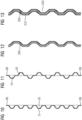
- the Figure 10 shows a possible alternative design for a side wall or front wall of a housing, the cross-section or profile of which, viewed from the plane of the edge region RB, has outwardly extending trapezoidal ribs 50 with external flat roof regions 51.
- the Figure 11 shows another possible alternative design for a side wall or front wall, in which both outwardly projecting ribs 50 and inwardly projecting grooves 70 are provided to enlarge the surface of the housing.
- the Figure 12 shows a design for a side wall or front wall according to the invention, which is covered or coated on its inside with an electrically insulating, thermally conductive material 300.
- the insulating material 300 lies on the inside of the housing wall 41 without a gap.
- the Figure 13 shows an alternative design for a side wall or end wall according to the invention, in which the inside is also covered with an electrically insulating material 300.
- the material 300 is in turn covered or coated on its side facing away from the wall area with an electrically conductive material 310.
- the electrically conductive material 310, the electrically insulating, thermally conductive material 300 and the wall area together form a cross-section corresponding to a sandwich structure 320.
- the Figure 14 shows a top view of the Figure 5 shown side wall 41 of the housing 40 or the side wall area 411 of this side wall 41.
- the side wall area 411 has a cross section corresponding to the exemplary design of the Figure 10 whereby trapezoidal ribs 50 are formed.
Landscapes
- Engineering & Computer Science (AREA)
- Manufacturing & Machinery (AREA)
- Chemical & Material Sciences (AREA)
- Chemical Kinetics & Catalysis (AREA)
- Electrochemistry (AREA)
- General Chemical & Material Sciences (AREA)
- Secondary Cells (AREA)
Claims (13)
- Module (10) accumulateur d'énergie,
comportant au moins :une boîte (40) parallélépipédique fermée ayant quatre parois (41, 42) latérales et deux parois (43, 44) frontales, dans laquelle sont disposées au moins deux éléments (20, 30) d'accumulateur,caractérisé en ce quedes parois (41, 42) latérales de la boîte (40) sont en un matériau conducteur de la chaleur et ont chacune au moins une partie (411, 421) de paroi latérale de section transversale ondulée, tant de la face (A) extérieure qu'également de la face (I) intérieure de la paroi (41, 42) latérale, dans lequel les au moins deux parois (41, 42) latérales sont fabriquées en une ou en plusieurs tôles métalliques, dans lequel les faces (I) intérieures d'au moins les parties (411, 421) de paroi latérale sont habillées ou revêtues chacune d'un matériau (300) conducteur de la chaleur isolant électriquement, qui s'applique sans fissure à la face (I) intérieure, dans lequel le matériau (300) est, sur sa face non tournée vers la partie (411, 421) de paroi latérale, habillé ou revêtu d'un matériau (310) conducteur de l'électricité, qui s'applique sans fissure au matériau (300) conducteur de la chaleur isolant électriquement, dans lequel la partie (411, 421) de paroi latérale, le matériau (300) conducteur de la chaleur isolant électriquement et le matériau (310) conducteur électriquement forment une structure (320) en sandwich. - Module (10) accumulateur d'énergie suivant la revendication 1,
caractérisé en ce quechaque éminence (E) sur la face (A) extérieure de la partie (411, 421) de paroi latérale est opposée à une cavité (V) correspondante sur la face (I) intérieure de la partie (411, 421) de paroi latérale, etchaque cavité (V) sur la face (A) extérieure de la partie (411, 421) de paroi latérale est opposée à une éminence (E) correspondante sur la face (I) intérieure de la partie (411, 421) de paroi latérale. - Module (10) accumulateur d'énergie suivant la revendication 1 ou 2,
caractérisé en ce que
l'épaisseur de paroi dans les parties (411, 421) de paroi latérale est respectivement constante. - Module (10) accumulateur d'énergie suivant l'une des revendications précédentes,
caractérisé en ce que
la section transversale ondulée des parties (411, 421) de paroi latérale a été formée par déformation du matériau conducteur de la chaleur, en particulier au moyen d'un procédé d'emboutissage profond. - Module (10) accumulateur d'énergie suivant l'une des revendications précédentes,
caractérisé en ce que
les au moins deux parois (41, 42) latérales sont chacune planes du côté du bord et ont, dans leurs parties intérieures, chacune au moins une partie (411, 421) de paroi latérale, dans lequel les parties (411, 421) de paroi latérale sont entourées chacune d'une partie (RB) de bord plane, faisant le tour, de la paroi (41, 42) latérale. - Module (10) accumulateur d'énergie suivant l'une des revendications précédentes,
caractérisé en ce que
les parties (411, 421) de paroi latérale ont chacune des nervures (50) et/ou des rainures (70), qui s'étendent parallèlement suivant un sens d'écoulement de fluide donné à l'avance. - Module (10) accumulateur d'énergie suivant la revendication 1,
caractérisé en ce que
le matériau (300) est, sur sa face non tournée vers la partie (411, 421) de paroi latérale, habillé ou revêtu d'un matériau (310) conducteur de l'électricité, qui s'applique sans fissure au matériau (300) conducteur de la chaleur isolant électriquement, dans lequel la partie (411, 421) de paroi latérale, le matériau (300) conducteur de la chaleur isolant électriquement et le matériau (310) conducteur électriquement forment une structure (320) en sandwich. - Module (10) accumulateur d'énergie suivant la revendication 1 ou 7,
caractérisé en ce qu'
entre au moins l'un des éléments (20, 30) d'accumulateur et de la face (I) intérieure de la partie (411, 421) de paroi latérale, du matériau (300) conducteur de la chaleur isolant électriquement ou du matériau (310) conducteur électriquement est disposée au moins une entretoise (55) isolante électriquement pour séparer mécaniquement le au moins un élément (20, 30) d'accumulateur de la boîte (40). - Module (10) accumulateur d'énergie suivant l'une des revendications précédentes,
caractérisé en ce que
dans la boîte (40) est disposé un dispositif (60) de circulation, qui sert à faire circuler un fluide à l'intérieur de la boîte (40) . - Module (10) accumulateur d'énergie suivant l'une des revendications précédentes,
caractérisé en ce qu'
au moins l'une des parois (43, 43) frontales a une partie (431, 441) de paroi frontale de section transversale ondulée, tant de la face (A) extérieure qu'également de la face (I) intérieure de la paroi (43, 44) frontale, dans lequel la partie (431, 441) de paroi frontale respective est conformée, en particulier de manière à correspondre à une partie (411, 421) de paroi latérale suivant les revendications 2 à 10. - Véhicule, en particulier véhicule (100) ferroviaire,
caractérisé en ce que
il a au moins un module (10) accumulateur d'énergie suivant l'une des revendications précédentes. - Véhicule suivant la revendication 11,
caractérisé en ce que
le véhicule a au moins un dispositif (110) de circulation, en particulier au moins un ventilateur, qui est agencé de manière à ce qu'un courant de fluide par lui produit soit dirigé suivant une direction longitudinale de nervures (50) et/ou de rainures (70) des parties (411, 421) de paroi latérale. - Véhicule suivant la revendication 11 ou 12,
caractérisé en ce que
les nervures (50) et/ou les rainures (70) constituées dans les parties (411, 421) de paroi latérale sont dirigées parallèlement à une direction longitudinale du véhicule.
Applications Claiming Priority (1)
| Application Number | Priority Date | Filing Date | Title |
|---|---|---|---|
| DE102021202115.8A DE102021202115A1 (de) | 2021-03-04 | 2021-03-04 | Energiespeichereinrichtung mit Speicherzelle |
Publications (2)
| Publication Number | Publication Date |
|---|---|
| EP4053973A1 EP4053973A1 (fr) | 2022-09-07 |
| EP4053973B1 true EP4053973B1 (fr) | 2024-05-22 |
Family
ID=80461214
Family Applications (1)
| Application Number | Title | Priority Date | Filing Date |
|---|---|---|---|
| EP22158568.0A Active EP4053973B1 (fr) | 2021-03-04 | 2022-02-24 | Module accumulateur d'énergie |
Country Status (2)
| Country | Link |
|---|---|
| EP (1) | EP4053973B1 (fr) |
| DE (1) | DE102021202115A1 (fr) |
Family Cites Families (9)
| Publication number | Priority date | Publication date | Assignee | Title |
|---|---|---|---|---|
| DE102011000353B4 (de) | 2011-01-27 | 2026-02-05 | Dr. Ing. H.C. F. Porsche Aktiengesellschaft | Batterie |
| DE102011086049A1 (de) | 2011-11-10 | 2013-05-16 | Sb Limotive Company Ltd. | Batterie mit einer Vielzahl von Zellen im Innern eines geschlossenen Batteriegehäuses und Kraftfahrzeug |
| CN104466303B (zh) | 2013-09-24 | 2017-09-29 | 微宏动力系统(湖州)有限公司 | 相变电池组 |
| JP5574309B1 (ja) | 2013-12-02 | 2014-08-20 | サーチウェア株式会社 | 組電池およびこれを搭載した移動体 |
| CN108496261B (zh) | 2016-01-15 | 2021-03-16 | 株式会社村田制作所 | 电池组 |
| TW201743498A (zh) | 2016-04-01 | 2017-12-16 | A123系統有限責任公司 | 具有散熱密封材料之電池模組及其方法 |
| KR20200001692A (ko) | 2018-06-28 | 2020-01-07 | 현대자동차주식회사 | 차량용 배터리 모듈 |
| US11949060B2 (en) | 2018-09-11 | 2024-04-02 | Energizer Brands, Llc | Rechargeable hearing aid battery with slotted grommet |
| DE102019108386A1 (de) | 2019-04-01 | 2020-10-01 | Bayerische Motoren Werke Aktiengesellschaft | Batterie mit Halteeinrichtung sowie Kraftfahrzeug |
-
2021
- 2021-03-04 DE DE102021202115.8A patent/DE102021202115A1/de not_active Withdrawn
-
2022
- 2022-02-24 EP EP22158568.0A patent/EP4053973B1/fr active Active
Also Published As
| Publication number | Publication date |
|---|---|
| DE102021202115A1 (de) | 2022-09-08 |
| EP4053973A1 (fr) | 2022-09-07 |
Similar Documents
| Publication | Publication Date | Title |
|---|---|---|
| DE102012012294B4 (de) | Fahrzeug mit einer Batterieanordnung | |
| EP2497145B1 (fr) | Dispositif accumulateur d'énergie | |
| EP4154346A1 (fr) | Dispositif de stockage d'énergie comprenant un module de cellule de batterie et un dispositif de refroidissement, de préférence pour un véhicule au moins partiellement électrique, et procédé de fabrication du dispositif de stockage d'énergie | |
| DE112007002809T5 (de) | Elektrisches Leistungszuführsystem | |
| EP1835251A1 (fr) | Dispositif destiné au refroidissement d'éléments électriques | |
| DE102017202768A1 (de) | Energiespeicheranordnung und Kraftfahrzeug | |
| DE102017005313B4 (de) | Energiespeicher und Kraftfahrzeug | |
| DE102008034873A1 (de) | Batterie, insbesondere Fahrzeugbatterie | |
| DE102021110496A1 (de) | Batteriepack-modul | |
| DE102017219176A1 (de) | Batteriemodul für eine Hochvoltbatterie eines Kraftfahrzeugs, Hochvoltbatterie sowie Kraftfahrzeug | |
| EP4309232A1 (fr) | Dispositif de refroidissement comprenant un dissipateur thermique et des éléments de refroidissement intermédiaires, accumulateur d'énergie électrique et véhicule automobile | |
| DE102017005315A1 (de) | Batteriekasten | |
| EP4449543A1 (fr) | Dispositif de stockage d'énergie électrique avec régulation de température de borne et conduit de gaz | |
| DE102008034855A1 (de) | Zellverbund für eine Batterie | |
| DE102017005400A1 (de) | Energiespeicheranordnung und Kraftfahrzeug | |
| DE102022123177A1 (de) | Batterie mit umschliessung für batteriezellengruppen | |
| EP4120432A2 (fr) | Dispositif d'accumulation d'énergie doté d'un module d'élément de batterie et d'un dispositif de refroidissement de feuille, de préférence pour un véhicule au moins partiellement électrique et procédé de fabrication du dispositif d'accumulation d'énergie | |
| DE60212504T2 (de) | Kühlvorrichtung an der Gehäuse einer sekundären Batterie | |
| DE102018215580B4 (de) | Hochvoltbatterie aufweisend Batteriezellen mit einzelwandigen und doppelwandigen Zellgehäusen sowie Kraftfahrzeug | |
| DE102015206522B4 (de) | Mehrfunktionaler Energiespeicherboden | |
| DE102021126133A1 (de) | Kraftfahrzeug und Batterie mit Kühlelement | |
| DE102017211365A1 (de) | Energiespeichereinrichtung für ein Kraftfahrzeug und Kraftfahrzeug | |
| EP4053973B1 (fr) | Module accumulateur d'énergie | |
| DE102017005328B4 (de) | Energiespeicheranordnung und Kraftfahrzeug | |
| DE102017009640A1 (de) | Kühlvorrichtung |
Legal Events
| Date | Code | Title | Description |
|---|---|---|---|
| PUAI | Public reference made under article 153(3) epc to a published international application that has entered the european phase |
Free format text: ORIGINAL CODE: 0009012 |
|
| STAA | Information on the status of an ep patent application or granted ep patent |
Free format text: STATUS: THE APPLICATION HAS BEEN PUBLISHED |
|
| AK | Designated contracting states |
Kind code of ref document: A1 Designated state(s): AL AT BE BG CH CY CZ DE DK EE ES FI FR GB GR HR HU IE IS IT LI LT LU LV MC MK MT NL NO PL PT RO RS SE SI SK SM TR |
|
| STAA | Information on the status of an ep patent application or granted ep patent |
Free format text: STATUS: REQUEST FOR EXAMINATION WAS MADE |
|
| 17P | Request for examination filed |
Effective date: 20230303 |
|
| RBV | Designated contracting states (corrected) |
Designated state(s): AL AT BE BG CH CY CZ DE DK EE ES FI FR GB GR HR HU IE IS IT LI LT LU LV MC MK MT NL NO PL PT RO RS SE SI SK SM TR |
|
| GRAP | Despatch of communication of intention to grant a patent |
Free format text: ORIGINAL CODE: EPIDOSNIGR1 |
|
| STAA | Information on the status of an ep patent application or granted ep patent |
Free format text: STATUS: GRANT OF PATENT IS INTENDED |
|
| INTG | Intention to grant announced |
Effective date: 20240105 |
|
| GRAS | Grant fee paid |
Free format text: ORIGINAL CODE: EPIDOSNIGR3 |
|
| GRAA | (expected) grant |
Free format text: ORIGINAL CODE: 0009210 |
|
| STAA | Information on the status of an ep patent application or granted ep patent |
Free format text: STATUS: THE PATENT HAS BEEN GRANTED |
|
| AK | Designated contracting states |
Kind code of ref document: B1 Designated state(s): AL AT BE BG CH CY CZ DE DK EE ES FI FR GB GR HR HU IE IS IT LI LT LU LV MC MK MT NL NO PL PT RO RS SE SI SK SM TR |
|
| REG | Reference to a national code |
Ref country code: GB Ref legal event code: FG4D Free format text: NOT ENGLISH |
|
| REG | Reference to a national code |
Ref country code: CH Ref legal event code: EP |
|
| REG | Reference to a national code |
Ref country code: DE Ref legal event code: R096 Ref document number: 502022000919 Country of ref document: DE |
|
| REG | Reference to a national code |
Ref country code: IE Ref legal event code: FG4D Free format text: LANGUAGE OF EP DOCUMENT: GERMAN |
|
| REG | Reference to a national code |
Ref country code: LT Ref legal event code: MG9D |
|
| REG | Reference to a national code |
Ref country code: NL Ref legal event code: MP Effective date: 20240522 |
|
| PG25 | Lapsed in a contracting state [announced via postgrant information from national office to epo] |
Ref country code: IS Free format text: LAPSE BECAUSE OF FAILURE TO SUBMIT A TRANSLATION OF THE DESCRIPTION OR TO PAY THE FEE WITHIN THE PRESCRIBED TIME-LIMIT Effective date: 20240922 |
|
| PG25 | Lapsed in a contracting state [announced via postgrant information from national office to epo] |
Ref country code: BG Free format text: LAPSE BECAUSE OF FAILURE TO SUBMIT A TRANSLATION OF THE DESCRIPTION OR TO PAY THE FEE WITHIN THE PRESCRIBED TIME-LIMIT Effective date: 20240522 |
|
| PG25 | Lapsed in a contracting state [announced via postgrant information from national office to epo] |
Ref country code: HR Free format text: LAPSE BECAUSE OF FAILURE TO SUBMIT A TRANSLATION OF THE DESCRIPTION OR TO PAY THE FEE WITHIN THE PRESCRIBED TIME-LIMIT Effective date: 20240522 Ref country code: FI Free format text: LAPSE BECAUSE OF FAILURE TO SUBMIT A TRANSLATION OF THE DESCRIPTION OR TO PAY THE FEE WITHIN THE PRESCRIBED TIME-LIMIT Effective date: 20240522 |
|
| PG25 | Lapsed in a contracting state [announced via postgrant information from national office to epo] |
Ref country code: GR Free format text: LAPSE BECAUSE OF FAILURE TO SUBMIT A TRANSLATION OF THE DESCRIPTION OR TO PAY THE FEE WITHIN THE PRESCRIBED TIME-LIMIT Effective date: 20240823 |
|
| PG25 | Lapsed in a contracting state [announced via postgrant information from national office to epo] |
Ref country code: PT Free format text: LAPSE BECAUSE OF FAILURE TO SUBMIT A TRANSLATION OF THE DESCRIPTION OR TO PAY THE FEE WITHIN THE PRESCRIBED TIME-LIMIT Effective date: 20240923 |
|
| PG25 | Lapsed in a contracting state [announced via postgrant information from national office to epo] |
Ref country code: NL Free format text: LAPSE BECAUSE OF FAILURE TO SUBMIT A TRANSLATION OF THE DESCRIPTION OR TO PAY THE FEE WITHIN THE PRESCRIBED TIME-LIMIT Effective date: 20240522 |
|
| PG25 | Lapsed in a contracting state [announced via postgrant information from national office to epo] |
Ref country code: ES Free format text: LAPSE BECAUSE OF FAILURE TO SUBMIT A TRANSLATION OF THE DESCRIPTION OR TO PAY THE FEE WITHIN THE PRESCRIBED TIME-LIMIT Effective date: 20240522 |
|
| PG25 | Lapsed in a contracting state [announced via postgrant information from national office to epo] |
Ref country code: PL Free format text: LAPSE BECAUSE OF FAILURE TO SUBMIT A TRANSLATION OF THE DESCRIPTION OR TO PAY THE FEE WITHIN THE PRESCRIBED TIME-LIMIT Effective date: 20240522 |
|
| PG25 | Lapsed in a contracting state [announced via postgrant information from national office to epo] |
Ref country code: LV Free format text: LAPSE BECAUSE OF FAILURE TO SUBMIT A TRANSLATION OF THE DESCRIPTION OR TO PAY THE FEE WITHIN THE PRESCRIBED TIME-LIMIT Effective date: 20240522 |
|
| PG25 | Lapsed in a contracting state [announced via postgrant information from national office to epo] |
Ref country code: PT Free format text: LAPSE BECAUSE OF FAILURE TO SUBMIT A TRANSLATION OF THE DESCRIPTION OR TO PAY THE FEE WITHIN THE PRESCRIBED TIME-LIMIT Effective date: 20240923 Ref country code: PL Free format text: LAPSE BECAUSE OF FAILURE TO SUBMIT A TRANSLATION OF THE DESCRIPTION OR TO PAY THE FEE WITHIN THE PRESCRIBED TIME-LIMIT Effective date: 20240522 Ref country code: NO Free format text: LAPSE BECAUSE OF FAILURE TO SUBMIT A TRANSLATION OF THE DESCRIPTION OR TO PAY THE FEE WITHIN THE PRESCRIBED TIME-LIMIT Effective date: 20240822 Ref country code: NL Free format text: LAPSE BECAUSE OF FAILURE TO SUBMIT A TRANSLATION OF THE DESCRIPTION OR TO PAY THE FEE WITHIN THE PRESCRIBED TIME-LIMIT Effective date: 20240522 Ref country code: LV Free format text: LAPSE BECAUSE OF FAILURE TO SUBMIT A TRANSLATION OF THE DESCRIPTION OR TO PAY THE FEE WITHIN THE PRESCRIBED TIME-LIMIT Effective date: 20240522 Ref country code: IS Free format text: LAPSE BECAUSE OF FAILURE TO SUBMIT A TRANSLATION OF THE DESCRIPTION OR TO PAY THE FEE WITHIN THE PRESCRIBED TIME-LIMIT Effective date: 20240922 Ref country code: HR Free format text: LAPSE BECAUSE OF FAILURE TO SUBMIT A TRANSLATION OF THE DESCRIPTION OR TO PAY THE FEE WITHIN THE PRESCRIBED TIME-LIMIT Effective date: 20240522 Ref country code: GR Free format text: LAPSE BECAUSE OF FAILURE TO SUBMIT A TRANSLATION OF THE DESCRIPTION OR TO PAY THE FEE WITHIN THE PRESCRIBED TIME-LIMIT Effective date: 20240823 Ref country code: FI Free format text: LAPSE BECAUSE OF FAILURE TO SUBMIT A TRANSLATION OF THE DESCRIPTION OR TO PAY THE FEE WITHIN THE PRESCRIBED TIME-LIMIT Effective date: 20240522 Ref country code: ES Free format text: LAPSE BECAUSE OF FAILURE TO SUBMIT A TRANSLATION OF THE DESCRIPTION OR TO PAY THE FEE WITHIN THE PRESCRIBED TIME-LIMIT Effective date: 20240522 Ref country code: BG Free format text: LAPSE BECAUSE OF FAILURE TO SUBMIT A TRANSLATION OF THE DESCRIPTION OR TO PAY THE FEE WITHIN THE PRESCRIBED TIME-LIMIT Effective date: 20240522 Ref country code: RS Free format text: LAPSE BECAUSE OF FAILURE TO SUBMIT A TRANSLATION OF THE DESCRIPTION OR TO PAY THE FEE WITHIN THE PRESCRIBED TIME-LIMIT Effective date: 20240822 |
|
| PG25 | Lapsed in a contracting state [announced via postgrant information from national office to epo] |
Ref country code: DK Free format text: LAPSE BECAUSE OF FAILURE TO SUBMIT A TRANSLATION OF THE DESCRIPTION OR TO PAY THE FEE WITHIN THE PRESCRIBED TIME-LIMIT Effective date: 20240522 |
|
| PG25 | Lapsed in a contracting state [announced via postgrant information from national office to epo] |
Ref country code: EE Free format text: LAPSE BECAUSE OF FAILURE TO SUBMIT A TRANSLATION OF THE DESCRIPTION OR TO PAY THE FEE WITHIN THE PRESCRIBED TIME-LIMIT Effective date: 20240522 |
|
| PG25 | Lapsed in a contracting state [announced via postgrant information from national office to epo] |
Ref country code: CZ Free format text: LAPSE BECAUSE OF FAILURE TO SUBMIT A TRANSLATION OF THE DESCRIPTION OR TO PAY THE FEE WITHIN THE PRESCRIBED TIME-LIMIT Effective date: 20240522 |
|
| PG25 | Lapsed in a contracting state [announced via postgrant information from national office to epo] |
Ref country code: RO Free format text: LAPSE BECAUSE OF FAILURE TO SUBMIT A TRANSLATION OF THE DESCRIPTION OR TO PAY THE FEE WITHIN THE PRESCRIBED TIME-LIMIT Effective date: 20240522 Ref country code: SK Free format text: LAPSE BECAUSE OF FAILURE TO SUBMIT A TRANSLATION OF THE DESCRIPTION OR TO PAY THE FEE WITHIN THE PRESCRIBED TIME-LIMIT Effective date: 20240522 |
|
| PG25 | Lapsed in a contracting state [announced via postgrant information from national office to epo] |
Ref country code: SK Free format text: LAPSE BECAUSE OF FAILURE TO SUBMIT A TRANSLATION OF THE DESCRIPTION OR TO PAY THE FEE WITHIN THE PRESCRIBED TIME-LIMIT Effective date: 20240522 Ref country code: RO Free format text: LAPSE BECAUSE OF FAILURE TO SUBMIT A TRANSLATION OF THE DESCRIPTION OR TO PAY THE FEE WITHIN THE PRESCRIBED TIME-LIMIT Effective date: 20240522 Ref country code: EE Free format text: LAPSE BECAUSE OF FAILURE TO SUBMIT A TRANSLATION OF THE DESCRIPTION OR TO PAY THE FEE WITHIN THE PRESCRIBED TIME-LIMIT Effective date: 20240522 Ref country code: DK Free format text: LAPSE BECAUSE OF FAILURE TO SUBMIT A TRANSLATION OF THE DESCRIPTION OR TO PAY THE FEE WITHIN THE PRESCRIBED TIME-LIMIT Effective date: 20240522 Ref country code: CZ Free format text: LAPSE BECAUSE OF FAILURE TO SUBMIT A TRANSLATION OF THE DESCRIPTION OR TO PAY THE FEE WITHIN THE PRESCRIBED TIME-LIMIT Effective date: 20240522 |
|
| PG25 | Lapsed in a contracting state [announced via postgrant information from national office to epo] |
Ref country code: IT Free format text: LAPSE BECAUSE OF FAILURE TO SUBMIT A TRANSLATION OF THE DESCRIPTION OR TO PAY THE FEE WITHIN THE PRESCRIBED TIME-LIMIT Effective date: 20240522 |
|
| REG | Reference to a national code |
Ref country code: DE Ref legal event code: R097 Ref document number: 502022000919 Country of ref document: DE |
|
| PLBE | No opposition filed within time limit |
Free format text: ORIGINAL CODE: 0009261 |
|
| STAA | Information on the status of an ep patent application or granted ep patent |
Free format text: STATUS: NO OPPOSITION FILED WITHIN TIME LIMIT |
|
| PG25 | Lapsed in a contracting state [announced via postgrant information from national office to epo] |
Ref country code: SI Free format text: LAPSE BECAUSE OF FAILURE TO SUBMIT A TRANSLATION OF THE DESCRIPTION OR TO PAY THE FEE WITHIN THE PRESCRIBED TIME-LIMIT Effective date: 20240522 |
|
| 26N | No opposition filed |
Effective date: 20250225 |
|
| PGFP | Annual fee paid to national office [announced via postgrant information from national office to epo] |
Ref country code: DE Payment date: 20250417 Year of fee payment: 4 |
|
| PGFP | Annual fee paid to national office [announced via postgrant information from national office to epo] |
Ref country code: CH Payment date: 20250512 Year of fee payment: 4 |
|
| REG | Reference to a national code |
Ref country code: DE Ref legal event code: R081 Ref document number: 502022000919 Country of ref document: DE Owner name: SIEMENS MOBILITY GMBH, DE Free format text: FORMER OWNER: SIEMENS MOBILITY GMBH, 81739 MUENCHEN, DE |
|
| PG25 | Lapsed in a contracting state [announced via postgrant information from national office to epo] |
Ref country code: SE Free format text: LAPSE BECAUSE OF FAILURE TO SUBMIT A TRANSLATION OF THE DESCRIPTION OR TO PAY THE FEE WITHIN THE PRESCRIBED TIME-LIMIT Effective date: 20240522 |
|
| PG25 | Lapsed in a contracting state [announced via postgrant information from national office to epo] |
Ref country code: MC Free format text: LAPSE BECAUSE OF FAILURE TO SUBMIT A TRANSLATION OF THE DESCRIPTION OR TO PAY THE FEE WITHIN THE PRESCRIBED TIME-LIMIT Effective date: 20240522 |
|
| PG25 | Lapsed in a contracting state [announced via postgrant information from national office to epo] |
Ref country code: LU Free format text: LAPSE BECAUSE OF NON-PAYMENT OF DUE FEES Effective date: 20250224 |
|
| REG | Reference to a national code |
Ref country code: BE Ref legal event code: MM Effective date: 20250228 |
|
| PG25 | Lapsed in a contracting state [announced via postgrant information from national office to epo] |
Ref country code: BE Free format text: LAPSE BECAUSE OF NON-PAYMENT OF DUE FEES Effective date: 20250228 |
|
| PG25 | Lapsed in a contracting state [announced via postgrant information from national office to epo] |
Ref country code: IE Free format text: LAPSE BECAUSE OF NON-PAYMENT OF DUE FEES Effective date: 20250224 |
|
| PGFP | Annual fee paid to national office [announced via postgrant information from national office to epo] |
Ref country code: GB Payment date: 20260310 Year of fee payment: 5 |
|
| PGFP | Annual fee paid to national office [announced via postgrant information from national office to epo] |
Ref country code: AT Payment date: 20260301 Year of fee payment: 5 |
|
| PGFP | Annual fee paid to national office [announced via postgrant information from national office to epo] |
Ref country code: FR Payment date: 20260213 Year of fee payment: 5 |