EP4053973B1 - Energiespeichermodul - Google Patents
Energiespeichermodul Download PDFInfo
- Publication number
- EP4053973B1 EP4053973B1 EP22158568.0A EP22158568A EP4053973B1 EP 4053973 B1 EP4053973 B1 EP 4053973B1 EP 22158568 A EP22158568 A EP 22158568A EP 4053973 B1 EP4053973 B1 EP 4053973B1
- Authority
- EP
- European Patent Office
- Prior art keywords
- side wall
- energy storage
- conductive material
- storage module
- housing
- Prior art date
- Legal status (The legal status is an assumption and is not a legal conclusion. Google has not performed a legal analysis and makes no representation as to the accuracy of the status listed.)
- Active
Links
Images



Classifications
-
- H—ELECTRICITY
- H01—ELECTRIC ELEMENTS
- H01M—PROCESSES OR MEANS, e.g. BATTERIES, FOR THE DIRECT CONVERSION OF CHEMICAL ENERGY INTO ELECTRICAL ENERGY
- H01M10/00—Secondary cells; Manufacture thereof
- H01M10/60—Heating or cooling; Temperature control
- H01M10/65—Means for temperature control structurally associated with the cells
- H01M10/655—Solid structures for heat exchange or heat conduction
- H01M10/6551—Surfaces specially adapted for heat dissipation or radiation, e.g. fins or coatings
-
- Y—GENERAL TAGGING OF NEW TECHNOLOGICAL DEVELOPMENTS; GENERAL TAGGING OF CROSS-SECTIONAL TECHNOLOGIES SPANNING OVER SEVERAL SECTIONS OF THE IPC; TECHNICAL SUBJECTS COVERED BY FORMER USPC CROSS-REFERENCE ART COLLECTIONS [XRACs] AND DIGESTS
- Y02—TECHNOLOGIES OR APPLICATIONS FOR MITIGATION OR ADAPTATION AGAINST CLIMATE CHANGE
- Y02E—REDUCTION OF GREENHOUSE GAS [GHG] EMISSIONS, RELATED TO ENERGY GENERATION, TRANSMISSION OR DISTRIBUTION
- Y02E60/00—Enabling technologies; Technologies with a potential or indirect contribution to GHG emissions mitigation
- Y02E60/10—Energy storage using batteries
-
- Y—GENERAL TAGGING OF NEW TECHNOLOGICAL DEVELOPMENTS; GENERAL TAGGING OF CROSS-SECTIONAL TECHNOLOGIES SPANNING OVER SEVERAL SECTIONS OF THE IPC; TECHNICAL SUBJECTS COVERED BY FORMER USPC CROSS-REFERENCE ART COLLECTIONS [XRACs] AND DIGESTS
- Y02—TECHNOLOGIES OR APPLICATIONS FOR MITIGATION OR ADAPTATION AGAINST CLIMATE CHANGE
- Y02E—REDUCTION OF GREENHOUSE GAS [GHG] EMISSIONS, RELATED TO ENERGY GENERATION, TRANSMISSION OR DISTRIBUTION
- Y02E60/00—Enabling technologies; Technologies with a potential or indirect contribution to GHG emissions mitigation
- Y02E60/14—Thermal energy storage
Definitions
- the invention relates to an energy storage module with a cuboid-shaped housing and at least two storage cells arranged therein.
- document EN 10 2019 108386 A1 discloses a holding device for a battery of a motor vehicle, wherein the holding device has a receiving compartment for each of a plurality of prismatic cells, the boundary walls of which each have a wave-shaped cross-section along the vertical direction, increasing the stability of the holding device.
- document US 2020/006825 A1 a battery module for a vehicle, which is formed by a cooling channel module, side covers and a cover plate, wherein the cover plate has a wave-shaped cross-section.
- the invention is based on the object of specifying an energy storage module which ensures reliable heat dissipation to the surroundings of the housing and can easily prevent the energy storage module from overheating.
- This object is achieved by an energy storage module and a vehicle with at least one such energy storage module according to the features of the independent patent claims. Further developments are specified in the respective dependent patent claims.
- an energy storage module has at least one cuboid-shaped housing with four side walls and two end walls, in which at least two storage cells are arranged.
- at least two of the side walls of the housing are made of a thermally conductive material and each have at least one side wall region with a wavy cross-section on both the outside and the inside of the side wall, wherein the at least two side walls are made from one or more metal sheets, wherein the insides of at least the side wall regions are each covered or coated with an electrically insulating but thermally conductive material which rests on the inside without a gap, wherein the material is covered or coated on its side facing away from the side wall region with an electrically conductive material (310) which rests on the electrically insulating, thermally conductive material without a gap, wherein the side wall region), the electrically insulating, thermally conductive material and the electrically conductive material form a sandwich structure (320).
- An advantage of the energy storage module according to the invention is that the wave-shaped cross section of the side wall areas results in an increase in the surface area of the housing, which enables heat to be dissipated to the outside or to the ambient atmosphere of the housing without having to provide special cooling devices such as cooling fins or a separate cooling plate thermally connected to the housing.
- the cuboid-shaped housing has at least one side wall region with a wave-shaped cross-section on three or more cuboid partial surfaces or side walls.
- each elevation on the outside of the side wall region is opposite a corresponding depression on the inside of the side wall region, and each depression on the outside of the side wall region is opposite a corresponding elevation on the inside of the side wall region.
- the wall thickness in the side wall areas is constant.
- the wave-shaped cross section of the side wall regions has been formed by deformation of the thermally conductive material, in particular by means of a deep-drawing process.
- all four side walls and, if necessary, the end walls are made from one or more metal sheets, which are deep-drawn in whole or in sections.
- Suitable metal sheets include, for example, sheets made from aluminum or stainless steel.
- the at least two side walls are each flat on the edge and each have at least one side wall region in their inner region, wherein the side wall regions are each enclosed by a flat peripheral edge region of the side wall.
- the side walls are preferably each arranged at an angle to one or more adjacent side walls and end walls.
- Adjacent side walls can be formed by a common element, for example a common sheet metal, which is bent at one or more bending edges.
- the bending edges segment the common element into adjacent side walls of the housing.
- adjacent side walls can also be formed by separate housing parts, for example in the form of individual sheets, which have been placed at an angle to one another and connected to one another, preferably welded, screwed and/or riveted.
- housing is formed by separate housing parts, these are preferably connected to each other seamlessly or in a fluid-tight manner in order to form a hermetically sealed housing.
- Adjacent housing parts can be flat, folded, flanged or provided with a groove in the interface area or in the area of their contact edges.
- the side wall regions each have ribs and/or grooves or channels which extend parallel along a predetermined fluid flow direction.
- At least the inside of the side wall areas is covered or coated with an electrically insulating but thermally conductive material, which lies on the inside without a gap.
- the electrically insulating material preferably serves to electrically separate the storage cells from the housing.
- the material is covered or coated on its side facing away from the side wall region with an electrically conductive material which rests on the electrically insulating, thermally conductive material without a gap, wherein the side wall region, the electrically insulating, thermally conductive material and the electrically conductive material form a sandwich structure.
- the electrically conductive material or the inner lining formed thereby preferably has no electrical contact with the side wall of the housing or the outer housing wall.
- An inner lining or sandwich structure can advantageously prevent local temperature increases or so-called hotspots and thus lead to improved overall heat dissipation.
- At least one electrically insulating spacer for mechanically separating the at least one memory cell from the housing is arranged between at least one of the memory cells and the inner side of the side wall region, the electrically insulating, thermally conductive material or the electrically conductive material.
- Such a spacer can be provided as an alternative to covering the inside of a side wall area with an electrically insulating, thermally conductive material.
- fluid channels can be formed inside the housing by means of such spacers, which enable a fluid flow in the region of the inner sides of the housing.
- a circulation device is arranged in the housing, which serves to circulate a fluid inside the housing. This can advantageously achieve a homogeneous distribution of the heat emanating from the storage cells within the closed housing.
- a circulation device can be designed as a fan, for example, if air is circulated as the fluid in the housing.
- At least one of the end walls of the housing additionally has an end wall region with a wave-shaped cross-section on both the outside and the inside of the end wall, wherein the respective end wall region is designed in particular corresponding to a side wall region according to one or more of the above-described embodiments of the side wall regions.
- a vehicle according to the invention in particular a rail vehicle, has at least one energy storage module according to the invention.
- the vehicle further comprises a circulation device, in particular a fan, which is oriented such that a fluid flow generated by it is aligned along a longitudinal direction of ribs and/or grooves of the side wall regions.
- a circulation device in particular a fan, which is oriented such that a fluid flow generated by it is aligned along a longitudinal direction of ribs and/or grooves of the side wall regions.
- the ribs and/or grooves are aligned parallel to a longitudinal direction of the vehicle.
- At least one of the side walls or side wall regions may form a portion of the outer skin of the vehicle.
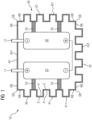
- the Figure 1 shows an embodiment of an energy storage module 10 according to the invention, which is equipped with two storage cells 20 and 30.
- the two storage cells 20 and 30 are in the embodiment according to Figure 1 electrically connected in series and are connected to external connection contacts or connection poles 11 and 12 of the energy storage module 10.
- the storage cells 20 and 30 can also be connected in parallel; additional storage cells can also be present, which can be connected in parallel or in series in any way.
- the storage cells 20, 30 are designed, for example, as lithium-ion cells.
- the storage cells 20 and 30 are accommodated in a common housing 40, the housing walls 41, 42, 43 and 44 of which surround or enclose the two storage cells 20 and 30.
- housing walls 41, 42, 43 of the housing 40 have housing wall regions 411, 421, 431 which enable heat to be dissipated to the surroundings of the housing 40 of the energy storage module 10 or to cool the storage cells 20, 30.
- a left side wall 41, a right side wall 42 as well as a lower end wall 43 and an upper end wall 44 are shown as examples.
- the wall areas 411 to 413 are flat in their respective outer area or in their respective edge area RB, but are wavy in their respective inner area for the purpose of increasing the surface area.
- Adjacent wall areas can be flat in the interface area SB as shown, alternatively they can be folded, flanged or provided with a groove.
- each elevation E on the outside A - relative to the respective edge region RB - of each of the side walls or end wall areas is opposite a corresponding depression V on the inside I.
- the respective wall thickness preferably remains constant, apart from manufacturing-related fluctuations.
- spacers 55 are provided, which preferably consist of electrically non-conductive but thermally conductive material.
- the spacers 55 can also be omitted if, for example, the storage cells 20 and 30 are to lie directly against a housing wall or be held by it.
- the side wall and end wall areas 411, 421 and 431 are shaped in such a way that, viewed from their respective edge area RB, they form outwardly projecting ribs 50, the longitudinal direction of which in the representation according to Figure 1 perpendicular to the image plane and forms a preferred direction for a fluid flow.
- the ribs 50 are preferably formed by material deformation, preferably by deep drawing, of the respective wall region 411, 421 or 431 It is advantageous if the wall areas 411, 421 and 431 are formed by deep-drawn sheets.
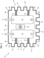
- the energy storage module 10 is additionally equipped with a circulation device 60, for example with a fan, which is arranged inside the housing 40 and circulates a fluid located inside the housing 40, for example air, another gas or an insulating liquid, in order to cool or heat the storage cells 20 and 30.
- a circulation device 60 for example with a fan, which is arranged inside the housing 40 and circulates a fluid located inside the housing 40, for example air, another gas or an insulating liquid, in order to cool or heat the storage cells 20 and 30.
- the Figure 3 shows a to the embodiment of the Figure 1 alternative embodiment of an energy storage module 10, in which the two side walls 41, 42 and the one end wall 43 are provided with grooves 70, viewed from the edge region RB of the respective wall.
- the longitudinal direction of the grooves 70 extends perpendicular to the image plane of the Figure 3 and forms a preferred fluid flow direction.
- the wall regions 411, 421 and 431 are formed by deep-drawn sheets.
- the Figure 4 shows a variant of the embodiment according to Figure 3 , in which a circulation device 60 is additionally arranged within the housing 40 of the energy storage module 10, which circulates a fluid located inside the housing 40 during operation of the energy storage module 10 and in particular during a charging or discharging process of the storage cells 20, 30 for the purpose of cooling or cooling the storage cells 20 and 30.
- a circulation device 60 is additionally arranged within the housing 40 of the energy storage module 10, which circulates a fluid located inside the housing 40 during operation of the energy storage module 10 and in particular during a charging or discharging process of the storage cells 20, 30 for the purpose of cooling or cooling the storage cells 20 and 30.
- the Figure 5 shows a further embodiment of an energy storage module 10 according to the invention, in a perspective view. From this illustration it is clear that the side wall areas 411 and 421 of the cuboid-shaped housing 40 are provided with grooves 70, which enable or simplify heat dissipation from the interior of the housing 40 to the outside.
- the above explanations in connection with the Figures 1 to 4 in the embodiment according to Figure 5 can also have corresponding side wall areas with grooves to enlarge the housing surface.
- FIG. 6 shows a further embodiment of an energy storage module 10 according to the invention, in a perspective view. From this illustration it is clear that in addition to the two side wall areas 411 and 421, an end wall area 431 of the end wall 44, which is opposite the end wall 43 carrying the connection contacts 11, 12, is also provided with grooves 70.
- the Figure 7 shows a rail vehicle 100 equipped with two energy storage modules 10.
- the left energy storage module 10 is an example of an energy storage module as used in connection with the Figure 1 has been explained, while the right energy storage module 10 is an energy storage module as described in connection with the Figure 3 has been explained.
- the rail vehicle 10 is additionally equipped with one or more fans 110, which cause a fluid flow close to the housing or air flow in the interior of the rail vehicle 100 for cooling the energy storage modules 10.
- the Figure 8 shows an embodiment of a rail vehicle 100 in which an energy storage module 10, which is, for example, one of the Figures 1 to 6 shown energy storage modules, is arranged in the area of the roof or a side or bottom wall of the rail vehicle 100 in such a way that ribs 50 or grooves 70 in housing wall areas of the housing 40 are cooled by the outside air, in particular the wind when the rail vehicle 100 is traveling.
- the side walls or the ribs 50 or grooves 70 of the side wall areas thus form sections of an outer skin 101 of the rail vehicle 100.
- FIG. 9 shows a further variant of the embodiment according to Figure 8
- a fan 110 is additionally provided inside the rail vehicle 100, which fan cools the side wall or front wall areas of the housing 40 located inside the rail vehicle.
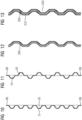
- the Figure 10 shows a possible alternative design for a side wall or front wall of a housing, the cross-section or profile of which, viewed from the plane of the edge region RB, has outwardly extending trapezoidal ribs 50 with external flat roof regions 51.
- the Figure 11 shows another possible alternative design for a side wall or front wall, in which both outwardly projecting ribs 50 and inwardly projecting grooves 70 are provided to enlarge the surface of the housing.
- the Figure 12 shows a design for a side wall or front wall according to the invention, which is covered or coated on its inside with an electrically insulating, thermally conductive material 300.
- the insulating material 300 lies on the inside of the housing wall 41 without a gap.
- the Figure 13 shows an alternative design for a side wall or end wall according to the invention, in which the inside is also covered with an electrically insulating material 300.
- the material 300 is in turn covered or coated on its side facing away from the wall area with an electrically conductive material 310.
- the electrically conductive material 310, the electrically insulating, thermally conductive material 300 and the wall area together form a cross-section corresponding to a sandwich structure 320.
- the Figure 14 shows a top view of the Figure 5 shown side wall 41 of the housing 40 or the side wall area 411 of this side wall 41.
- the side wall area 411 has a cross section corresponding to the exemplary design of the Figure 10 whereby trapezoidal ribs 50 are formed.
Landscapes
- Engineering & Computer Science (AREA)
- Manufacturing & Machinery (AREA)
- Chemical & Material Sciences (AREA)
- Chemical Kinetics & Catalysis (AREA)
- Electrochemistry (AREA)
- General Chemical & Material Sciences (AREA)
- Secondary Cells (AREA)
Description
- Die Erfindung betrifft ein Energiespeichermodul mit einem quaderförmigen Gehäuse sowie zumindest zwei darin angeordneten Speicherzellen.
- Eine beispielhafte Energiespeichereinrichtung ist in der US-Schrift
US 2018/301773 A1 beschrieben. - Dokument
DE 10 2019 108386 A1 offenbart eine Halteeinrichtung einer Batterie eines Kraftfahrzeugs, wobei die Halteeinrichtung für jede einer Vielzahl prismatischer Zellen ein Aufnahmefach aufweist, dessen Begrenzungswände jeweils entlang der Hochrichtung einen die Stabilität der Halteeinrichtung erhöhende wellenförmigen Querschnitt aufweisen. Ferner offenbart DokumentUS 2020/006825 A1 ein Batteriemodul für ein Fahrzeug, welches durch ein Kühlkanalmodul, Seitenabdeckungen und eine Deckplatte gebildet wird, wobei die Deckplatte einen wellenförmigen Querschnitt aufweist. - Der Erfindung liegt die Aufgabe zugrunde, ein Energiespeichermodul anzugeben, welches eine zuverlässige Wärmeabfuhr an die Umgebung des Gehäuses gewährleistet und ein Überhitzen der Energiespeichermoduls in einfacher Weise vermeiden kann. Diese Aufgabe wird durch ein Energiespeichermodul sowie ein Fahrzeug mit zumindest einem solchen Energiespeichermodul gemäß den Merkmalen der unabhängigen Patentansprüche gelöst. Weiterbildungen sind in jeweiligen abhängigen Patentansprüchen angegeben.
- Danach ist erfindungsgemäß vorgesehen, dass ein Energiespeichermodul zumindest ein quaderförmiges Gehäuse mit vier Seitenwänden und zwei Stirnwänden aufweist, in welchem zumindest zwei Speicherzellen angeordnet sind. Kennzeichnend sind zumindest zwei der Seitenwände des Gehäuses aus einem thermisch leitfähigen Material hergestellt und weisen jeweils zumindest einen Seitenwandbereich mit einem wellenförmigen Querschnitt sowohl der Außenseite als auch der Innenseite der Seitenwand auf, wobei die zumindest zwei Seitenwände aus einem oder mehreren Metallblechen gefertigt sind, wobei die Innenseiten zumindest der Seitenwandbereiche jeweils mit einem elektrisch isolierenden, jedoch thermisch leitfähigen Material verkleidet oder beschichtet sind, welches auf der Innenseite spaltfrei anliegt, wobei das Material auf seiner dem Seitenwandbereich abgewandten Seite mit einem elektrisch leitfähigen Material (310) verkleidet oder beschichtet ist, welches auf dem elektrisch isolierenden, thermisch leitfähigen Material spaltfrei anliegt, wobei der Seitenwandbereich), das elektrisch isolierende, thermisch leitfähige Material und das elektrisch leitfähige Material eine Sandwichstruktur (320) ausbilden.
- Ein Vorteil des erfindungsgemäßen Energiespeichermoduls ist darin zu sehen, dass durch den wellenförmigen Querschnitt der Seitenwandbereiche eine Oberflächenvergrößerung des Gehäuses erzielt wird, welche eine Wärmeabfuhr nach außen bzw. an die Umgebungsatmosphäre des Gehäuses ermöglichen, ohne besondere Kühleinrichtungen wie beispielsweise Kühlfinnen oder eine gesonderte mit dem Gehäuse thermisch verbundene Kühlplatte vorsehen zu müssen.
- Vorzugsweise weist das quaderförmige Gehäuse an drei oder mehr Quaderteilflächen bzw. Seitenwänden jeweils zumindest einen Seitenwandbereich mit einem wellenförmigen Querschnitt auf.
- Gemäß einer Weiterbildung liegt jeder Erhöhung auf der Außenseite des Seitenwandbereichs eine korrespondierende Vertiefung auf der Innenseite des Seitenwandbereichs gegenüber, und liegt jeder Vertiefung auf der Außenseite des Seitenwandbereichs eine korrespondierende Erhöhung auf der Innenseite des Seitenwandbereichs gegenüber.
- Gemäß einer weiteren Weiterbildung ist die Wandstärke in den Seitenwandbereichen konstant.
- Gemäß einer weiteren Weiterbildung ist der wellenförmige Querschnitt der Seitenwandbereiche durch Materialumformung des thermisch leitfähigen Materials, insbesondere mittels eines Tiefziehverfahrens, gebildet worden.
- Vorzugsweise alle vier Seitenwände sowie gegebenenfalls ergänzend die Stirnwände sind dabei aus einem oder mehreren Metallblechen gefertigt, welche ganz oder in Abschnitten tiefgezogen sind. Als Metallbleche eignen sich dabei beispielsweise Bleche aus einem Aluminium- oder Edelstahlmaterial.
- Gemäß einer weiteren Weiterbildung sind die zumindest zwei Seitenwände jeweils randseitig plan und weisen in ihrem Innenbereich jeweils zumindest einen Seitenwandbereich auf, wobei die Seitenwandbereiche jeweils von einem planen umlaufenden Randbereich der Seitenwand umschlossen sind.
- Die Seitenwände sind vorzugsweise jeweils winklig zu einem oder mehreren benachbarten Seitenwänden und Stirnwänden angeordnet.
- Benachbarte Seitenwände können durch ein gemeinsamen Element, beispielsweise ein gemeinsames Blech, gebildet sein, das an ein oder mehr Biegekanten umgebogen ist. Die Biegekanten segmentieren in diesem Fall das gemeinsame Element in benachbarte Seitenwände des Gehäuses.
- Alternativ können benachbarte Seitenwände auch durch separate Gehäuseteile, beispielsweise in Form von Einzelblechen, gebildet sein, die winklig aneinandergesetzt und miteinander verbunden, vorzugsweise verschweißt, verschraubt und/oder vernietet, worden sind.
- Wird das Gehäuse durch separate Gehäuseteile gebildet, so werden diese vorzugsweise lückenlos bzw. fluiddicht miteinander verbunden, um ein hermetisch dichtes Gehäuse zu bilden.
- Aneinander angrenzende Gehäuseteile können im Schnittstellenbereich bzw. im Bereich ihrer Berührungskanten plan, gefalzt, gebördelt oder mit einer Nut versehen sein.
- Gemäß einer weiteren Weiterbildung weisen die Seitenwandbereiche jeweils Rippen und/oder Nuten bzw. Rinnen auf, welche sich parallel entlang einer vorgegebenen Fluidstromrichtung erstrecken.
- Erfindungsgemäß ist zumindest die Innenseite der Seitenwandbereiche jeweils mit einem elektrisch isolierenden, jedoch thermisch leitfähigen Material verkleidet oder beschichtet, welches auf der Innenseite spaltfrei anliegt. Das elektrisch isolierende Material dient dabei vorzugsweise einer elektrischen Trennung der Speicherzellen vom Gehäuse.
- Gemäß einer auf der voranstehenden Weiterbildung basierenden weiteren Weiterbildung ist das Material auf seiner von dem Seitenwandbereich abgewandten Seite mit einem elektrisch leitfähigen Material verkleidet oder beschichtet, welches auf dem elektrisch isolierenden, thermisch leitfähigen Material spaltfrei anliegt, wobei der Seitenwandbereich, das elektrisch isolierende, thermisch leitfähige Material und das elektrisch leitfähige Material eine Sandwichstruktur ausbilden.
- Bei einer solchen Sandwichstruktur weist das elektrisch leitfähige Material bzw. die dadurch gebildete Innenverkleidung vorzugsweise keinen elektrischen Kontakt zur Seitenwand des Gehäuses äußeren Gehäusewand auf. Eine Innenverkleidung oder Sandwichstruktur kann in vorteilhafter Weise lokale Temperaturerhöhungen bzw. so genannte Hotspots vermeiden und so zu einer verbesserten Gesamtwärmeabfuhr führen.
- Gemäß einer weiteren Weiterbildung ist zwischen zumindest einer der Speicherzellen und der Innenseite des Seitenwandbereichs, dem elektrisch isolierenden, thermisch leitfähigen Material oder dem elektrisch leitfähigem Material zumindest ein elektrisch isolierender Abstandshalter für eine mechanische Trennung der zumindest einen Speicherzelle von dem Gehäuse angeordnet.
- Dabei kann ein solcher Abstandshalter alternativ zu einer Verkleidung der Innenseite eines Seitenwandbereichs mit einem elektrisch isolierenden, thermisch leitfähigen Material vorgesehen werden.
- Vorteilhaft können mittels solcher Abstandshalter im Inneren des Gehäuses Fluidkanäle gebildet werden, welche einen Fluidstrom im Bereich der Innenseiten des Gehäuses ermöglichen.
- Gemäß einer weiteren Weiterbildung ist in dem Gehäuse eine Umwälzeinrichtung angeordnet, welche einer Umwälzung eines Fluids im Inneren des Gehäuses dient. Hierdurch kann vorteilhaft eine homogene Verteilung der von den Speicherzellen ausgehenden Wärme innerhalb des geschlossenen Gehäuses erzielt werden. Eine solche Umwälzeinrichtung kann beispielsweise als ein Lüfter ausgestaltet sein, wenn als Fluid Luft in dem Gehäuse umgewälzt wird.
- Gemäß einer weiteren Weiterbildung weist ergänzend zumindest eine der Stirnwände des Gehäuses einen Stirnwandbereich mit einem wellenförmigen Querschnitt sowohl der Außenseite als auch der Innenseite der Stirnwand auf, wobei der jeweilige Stirnwandbereich insbesondere entsprechend einem Seitenwandbereich gemäß einem oder mehreren der vorstehend beschriebenen Ausgestaltungen der Seitenwandbereiche ausgestaltet ist.
- Ein erfindungsgemäßes Fahrzeug, insbesondere ein Schienenfahrzeug, weist zumindest ein erfindungsgemäßes Energiespeichermodul auf.
- Gemäß einer Weiterbildung des Fahrzeugs weist das Fahrzeug ferner eine Umwälzeinrichtung, insbesondere einen Lüfter, auf, welche derart ausgerichtet ist, dass ein von ihr erzeugter Fluidstrom entlang einer Längsrichtung von Rippen und/oder Nuten der Seitenwandbereiche ausgerichtet ist.
- Gemäß einer weiteren Weiterbildung des Fahrzeugs sind die Rippen und/oder Nuten parallel zu einer Längsrichtung des Fahrzeugs ausgerichtet.
- Zumindest eine der Seitenwände bzw. der Seitenwandbereiche kann einen Abschnitt der Außenhaut des Fahrzeugs bilden.
- Die Erfindung wird nachfolgend anhand von Ausführungsbeispielen näher erläutert. Dabei zeigen beispielhaft
- Fig. 1
- ein Ausführungsbeispiel für ein erfindungsgemäßes Energiespeichermodul mit Rippen,
- Fig. 2
- ein Ausführungsbeispiel für ein erfindungsgemäßes Energiespeichermodul mit Rippen und Umwälzeinrichtung,
- Fig. 3
- ein Ausführungsbeispiel für ein erfindungsgemäßes Energiespeichermodul mit Nuten,
- Fig. 4
- ein Ausführungsbeispiel für ein erfindungsgemäßes Energiespeichermodul mit Nuten und Umwälzeinrichtung,
- Fig. 5
- ein Ausführungsbeispiel für ein erfindungsgemäßes quaderförmiges Energiespeichermodul in einer perspektivischen Ansicht,
- Fig. 6
- ein weiteres Ausführungsbeispiel für ein erfindungsgemäßes quaderförmiges Energiespeichermodul in einer perspektivischen Ansicht,
- Fig. 7-9
- Ausführungsbeispiele für erfindungsgemäße Schienenfahrzeuge, die mit Ausführungsbeispielen für erfindungsgemäße Energiespeichermodule ausgestattet sind, und
- Fig. 10-14
- Ausführungsbeispiele für Querschnitte von Seiten- bzw. Stirnwänden für erfindungsgemäße Energiespeichermodule.
- In den Figuren werden der Übersicht halber für identische oder vergleichbare Elemente dieselben Bezugszeichen verwendet.
- Die
Figur 1 zeigt ein Ausführungsbeispiel für ein erfindungsgemäßes Energiespeichermodul 10, das mit zwei Speicherzellen 20 und 30 ausgestattet ist. Die beiden Speicherzellen 20 und 30 sind bei dem Ausführungsbeispiel gemäßFigur 1 elektrisch in Reihe geschaltet und stehen mit äußeren Anschlusskontakten bzw. Anschlusspolen 11 und 12 des Energiespeichermoduls 10 in Verbindung. Alternativ können die Speicherzellen 20 und 30 auch parallel geschaltet sein; auch können weitere Speicherzellen vorhanden sein, die in beliebiger Weise parallel oder in Reihe geschaltet sein können. Die Speicherzellen 20, 30 sind beispielsweise als Lithium-Ionen -Zellen ausgestaltet. - Die Speicherzellen 20 und 30 sind in einem gemeinsamen Gehäuse 40 untergebracht, dessen Gehäusewände 41, 42, 43 und 44 die beiden Speicherzellen 20 und 30 umgeben bzw. umschließen.
- Alle oder einige Gehäusewände 41, 42, 43 des Gehäuses 40 weisen Gehäusewandbereiche 411, 421, 431 auf, die eine Wärmeabfuhr an die Umgebung des Gehäuses 40 des Energiespeichermoduls 10 bzw. eine Kühlung der Speicherzellen 20, 30 ermöglichen.
- In dem schematischen Querschnitt gemäß
Figur 1 ist eine linke Seitenwand 41, eine rechte Seitenwand 42 sowie eine untere Stirnwand 43 und eine obere Stirnwand 44 beispielhaft dargestellt. Die Wandbereiche 411 bis 413 sind in ihrem jeweiligen äußeren Bereich bzw. in ihrem jeweiligen Randbereich RB plan, jedoch in jeweiligen inneren Bereich zum Zwecke der Oberflächenvergrößerung wellenförmig. Aneinandergrenzende Wandbereiche können im Schnittstellenbereich SB wie gezeigt plan sein, alternativ können sie gefalzt, gebördelt oder mit einer Nut versehen sein. - Bei den wellenförmigen Seitenwandbereichen 411, 421 bzw. Stirnwandbereich 431 ist jeweils die außenseitige Formgestaltung komplementär zu der innenseitigen Formgestaltung ausgestaltet. So lässt sich in der
Figur 1 erkennen, dass jeder Erhöhung E auf der Außenseite A - bezogen auf den jeweiligen Randbereich RB - jeder der Seitenwand bzw. Stirnwandbereiche jeweils eine korrespondierende Vertiefung V auf der Innenseite I gegenüberliegt. Die jeweilige Wandstärke bleibt dabei, von herstellungsbedingten Schwankungen abgesehen, vorzugsweise konstant. - Beispielsweise für eine mechanische Befestigung und einer elektrischen Isolation der Speicherzellen 20 und 30 am bzw. vom Gehäuse 40 sind Abstandshalter 55 vorgesehen, die vorzugsweise aus elektrisch nicht leitendem, jedoch thermisch leitendem Material bestehen. Die Abstandshalter 55 können auch weggelassen werden, wenn beispielsweise die Speicherzellen 20 und 30 direkt an einer Gehäusewand anliegen oder von dieser gehalten werden sollen.
- Bei dem Ausführungsbeispiel gemäß
Figur 1 sind die Seitenwand- und Stirnwandbereiche 411, 421 und 431 derart geformt, dass sie, ausgehend von ihrem jeweiligen Randbereich RB betrachtet, nach außen ragende Rippen 50 ausbilden, deren Längsrichtung sich bei der Darstellung gemäßFigur 1 senkrecht zur Bildebene parallel erstreckt und eine bevorzugte Richtung für einen Fluidstrom bildet. Die Rippen 50 sind vorzugsweise durch Materialumformung, vorzugsweise durch ein Tiefziehen, des jeweiligen Wandbereichs 411, 421 bzw. 431 gebildet worden. Vorteilhaft ist es, wenn die Wandbereiche 411, 421 und 431 durch tiefgezogene Bleche gebildet sind. - In der Ausführungsvariante gemäß
Figur 2 ist das Energiespeichermodul 10 zusätzlich mit einer Umwälzeinrichtung 60, beispielsweise mit einem Lüfter, ausgestattet, die innerhalb des Gehäuses 40 angeordnet ist und ein im Inneren des Gehäuses 40 befindliches Fluid, beispielsweise Luft, ein sonstiges Gas oder eine Isolationsflüssigkeit, umwälzt, um eine Kühlung bzw. Entwärmung der Speicherzellen 20 und 30 zu bewirken. - Die
Figur 3 zeigt ein zu dem Ausführungsbeispiel derFigur 1 alternatives Ausführungsbeispiel für ein Energiespeichermodul 10, bei dem die beiden Seitenwände 41, 42 sowie die eine Stirnwand 43 mit, vom Randbereich RB -der jeweiligen Wand betrachtet, mit Nuten 70 versehen sind. Die Längsrichtung der Nuten 70 erstreckt sich wiederum senkrecht zur Bildebene derFigur 3 und bildet eine bevorzugte Fluidstromrichtung. Auch hier ist es vorteilhaft, wenn die Wandbereiche 411, 421 und 431 durch tiefgezogene Bleche gebildet sind. - Die
Figur 4 zeigt eine Ausführungsvariante des Ausführungsbeispiels gemäßFigur 3 , bei welcher innerhalb des Gehäuses 40 des Energiespeichermoduls 10 zusätzlich eine Umwälzeinrichtung 60 angeordnet ist, die im Betrieb des Energiespeichermoduls 10 und insbesondere während eines Lade- oder Entladevorgangs der Speicherzellen 20, 30 ein im Inneren des Gehäuses 40 befindliches Fluid zwecks Kühlung bzw. Entwärmung der Speicherzellen 20 und 30 umwälzt. - Die
Figur 5 zeigt ein weiteres Ausführungsbeispiel eines erfindungsgemäßen Energiespeichermoduls 10, in einer perspektivischen Ansicht. Aus dieser Darstellung wird deutlich, dass die Seitenwandbereiche 411 und 421 des quaderförmigen Gehäuses 40 mit Nuten 70 versehen sind, die eine Wärmeabfuhr von Wärme aus dem Inneren des Gehäuses 40 nach außen ermöglichen bzw. vereinfachen. Diesbezüglich gelten die obigen Erläuterungen im Zusammenhang mit denFiguren 1 bis 4 bei dem Ausführungsbeispiel gemäßFigur 5 entsprechend. Ergänzend können auch die in der Ansicht nicht sichtbaren beiden weiteren Seitenwände entsprechende Seitenwandbereiche mit Nuten für eine Vergrößerung der Gehäuseoberfläche aufweisen. - Die
Figur 6 zeigt ein weiteres Ausführungsbeispiel eines erfindungsgemäßen Energiespeichermoduls 10, in einer perspektivischen Ansicht. Aus dieser Darstellung wird deutlich, dass zusätzlich zu den beiden Seitenwandbereichen 411 und 421 ein Stirnwandbereich 431 der Stirnwand 44, welche der die Anschlusskontakte 11, 12 tragenden Stirnwand 43 gegenüber liegt, ebenfalls mit Nuten 70 versehen ist. - Die
Figur 7 zeigt ein Schienenfahrzeug 100, das mit zwei Energiespeichermodulen 10 ausgestattet ist. Bei dem in derFigur 7 linken Energiespeichermodul 10 handelt es sich beispielhaft um ein Energiespeichermodul, wie es im Zusammenhang mit derFigur 1 erläutert worden ist, während es sich bei dem rechten Energiespeichermodul 10 um ein Energiespeichermodul, wie es im Zusammenhang mit derFigur 3 erläutert worden ist, handelt. - Vorteilhaft ist es, wenn das Schienenfahrzeug 10 zusätzlich mit einem oder mehreren Lüftern 110 ausgestattet ist, die zum Kühlen der Energiespeichermodule 10 einen gehäusenahen Fluidstrom bzw. Luftstrom im Inneren des Schienenfahrzeugs 100 hervorrufen.
- Die
Figur 8 zeigt ein Ausführungsbeispiel für ein Schienenfahrzeug 100, bei dem ein Energiespeichermodul 10, bei dem es sich beispielsweise um eines der in denFiguren 1 bis 6 dargestellten Energiespeichermodule handeln kann, im Bereich des Dachs oder einer Seiten- oder Bodenwand des Schienenfahrzeugs 100 derart angeordnet ist, dass Rippen 50 bzw. Nuten 70 in Gehäusewandbereichen Gehäuses 40 von der Außenluft, insbesondere dem Fahrtwind bei Fahrt des Schienenfahrzeugs 100, gekühlt werden. Die Seitenwände bzw. die Rippen 50 bzw. Nuten 70 der Seitenwandbereiche bilden somit Abschnitte einer Außenhaut 101 des Schienenfahrzeugs 100. - Die
Figur 9 zeigt eine weitere Variante des Ausführungsbeispiels gemäßFigur 8 . Bei dieser Ausführungsvariante ist im Inneren des Schienenfahrzeugs 100 zusätzlich ein Lüfter 110 vorgesehen, welcher die im Inneren des Schienenfahrzeugs befindlichen Seitenwand- bzw. Stirnwandbereiche des Gehäuses 40 kühlt. - Die
Figur 10 zeigt eine mögliche alternative Ausgestaltung für eine Seitenwand bzw. Stirnwand eines Gehäuses, deren Querschnitt bzw. Profil, betrachtet von der Ebene des Randbereichs RB, nach außen verlaufende trapezförmige Rippen 50 mit außenliegenden planen Dachbereichen 51 aufweisen. - Die
Figur 11 zeigt eine weitere mögliche alternative Ausgestaltung für eine Seitenwand bzw. Stirnwand, bei der sowohl nach außen herausstehende Rippen 50 als auch nach innen ragende Nuten 70 einer Vergrößerung der Oberfläche des Gehäuses vorgesehen sind. - Die
Figur 12 zeigt eine Ausgestaltung für eine erfindungsgemäße Seitenwand bzw. Stirnwand, die auf ihrer Innenseite mit einem elektrisch isolierenden, thermisch leitfähigen Material 300 verkleidet oder beschichtet ist. Das Isolationsmaterial 300 liegt dabei auf der Innenseite der Gehäusewand 41 spaltfrei an. - Die
Figur 13 zeigt eine alternative Ausgestaltung für eine erfindungsgemäße Seitenwand bzw. Stirnwand, bei welcher die Innenseite ebenfalls mit einem elektrisch isolierenden Material 300 verkleidet ist. Das Material 300 ist seinerseits auf seiner von dem Wandbereich abgewandten Seite mit einem elektrisch leitfähigen Material 310 verkleidet oder beschichtet. Das elektrisch leitfähige Material 310, das elektrisch isolierende, thermisch leitfähige Material 300 und der Wandbereich bilden zusammen einen Querschnitt entsprechend einer Sandwichstruktur 320. - Die
Figur 14 zeigt eine Draufsicht der in derFigur 5 dargestellten Seitenwand 41 des Gehäuses 40 bzw. des Seitenwandbereichs 411 dieser Seitenwand 41. Der Seitenwandbereich 411 weist einen Querschnitt entsprechend der beispielhaften Ausgestaltung derFigur 10 auf, wodurch trapezförmige Rippen 50 ausgebildet werden.
Claims (13)
- Energiespeichermodul (10),
zumindest aufweisend:ein quaderförmiges geschlossenes Gehäuse (40) mit vier Seitenwänden (41, 42) und zwei Stirnwänden (43, 44), in welchem zumindest zwei Speicherzellen (20, 30) angeordnet sind,dadurch gekennzeichnet, dasszumindest zwei der Seitenwände (41, 42) des Gehäuses (40) aus einem thermisch leitfähigen Material hergestellt sind und jeweils zumindest einen Seitenwandbereich (411, 421) mit einem wellenförmigen Querschnitt sowohl der Außenseite (A) als auch der Innenseite (I) der Seitenwand (41, 42) aufweisen, wobei die zumindest zwei Seitenwände (41, 42) aus einem oder mehreren Metallblechen gefertigt sind, wobei die Innenseiten (I) zumindest der Seitenwandbereiche (411, 421) jeweils mit einem elektrisch isolierenden, jedoch thermisch leitfähigen Material (300) verkleidet oder beschichtet sind, welches auf der Innenseite (I) spaltfrei anliegt, wobei das Material (300) auf seiner dem Seitenwandbereich (411, 421) abgewandten Seite mit einem elektrisch leitfähigen Material (310) verkleidet oder beschichtet ist, welches auf dem elektrisch isolierenden, thermisch leitfähigen Material (300) spaltfrei anliegt, wobei der Seitenwandbereich (411, 421), das elektrisch isolierende, thermisch leitfähige Material (300) und das elektrisch leitfähige Material (310) eine Sandwichstruktur (320) ausbilden. - Energiespeichermodul (10) nach Anspruch 1,
dadurch gekennzeichnet, dassjeder Erhöhung (E) auf der Außenseite (A) des Seitenwandbereichs (411, 421) eine korrespondierende Vertiefung (V) auf der Innenseite (I) des Seitenwandbereichs (411, 421) gegenüberliegt, undjeder Vertiefung (V) auf der Außenseite (A) des Seitenwandbereichs (411, 421) eine korrespondierende Erhöhung (E) auf der Innenseite (I) des Seitenwandbereichs (411, 421) gegenüberliegt. - Energiespeichermodul (10) nach Anspruch 1 oder 2,
dadurch gekennzeichnet, dass
die Wandstärke in den Seitenwandbereichen (411, 421) jeweils konstant ist. - Energiespeichermodul (10) nach einem der voranstehenden Ansprüche,
dadurch gekennzeichnet, dass
der wellenförmige Querschnitt der Seitenwandbereiche (411, 421) durch Materialumformung des thermisch leitfähigen Materials, insbesondere mittels eines Tiefziehverfahrens, gebildet worden ist. - Energiespeichermodul (10) nach einem der voranstehenden Ansprüche,
dadurch gekennzeichnet, dass
die zumindest zwei Seitenwände (41, 42) jeweils randseitig plan sind und in ihrem Innenbereich jeweils zumindest einen Seitenwandbereich (411, 421) aufweisen, wobei die Seitenwandbereiche (411, 421) jeweils von einem planen umlaufenden Randbereich (RB) der Seitenwand (41, 42) umschlossen sind. - Energiespeichermodul (10) nach einem der voranstehenden Ansprüche,
dadurch gekennzeichnet, dass
die Seitenwandbereiche (411, 421) jeweils Rippen (50) und/oder Nuten (70) aufweisen, welche sich parallel entlang einer vorgegebenen Fluidstromrichtung erstrecken. - Energiespeichermodul (10) nach Anspruch 1, dadurch gekennzeichnet, dass
das Material (300) auf seiner dem Seitenwandbereich (411, 421) abgewandten Seite mit einem elektrisch leitfähigen Material (310) verkleidet oder beschichtet ist, welches auf dem elektrisch isolierenden, thermisch leitfähigen Material (300) spaltfrei anliegt, wobei der Seitenwandbereich (411, 421), das elektrisch isolierende, thermisch leitfähige Material (300) und das elektrisch leitfähige Material (310) eine Sandwichstruktur (320) ausbilden. - Energiespeichermodul (10) nach Anspruch 1 oder 7
dadurch gekennzeichnet, dass
zwischen zumindest einer der Speicherzellen (20, 30) und der Innenseite (I) des Seitenwandbereichs (411, 421), dem elektrisch isolierenden, thermisch leitfähigen Material (300) oder dem elektrisch leitfähigem Material (310) zumindest ein elektrisch isolierender Abstandshalter (55) für eine mechanische Trennung der zumindest einen Speicherzelle (20, 30) von dem Gehäuse (40) angeordnet ist. - Energiespeichermodul (10) nach einem der voranstehenden Ansprüche,
dadurch gekennzeichnet, dass
in dem Gehäuse (40) eine Umwälzeinrichtung (60) angeordnet ist, welche einer Umwälzung eines Fluids im Inneren des Gehäuses (40) dient. - Energiespeichermodul (10) nach einem der voranstehenden Ansprüche,
dadurch gekennzeichnet, dass
zumindest eine der Stirnwände (43, 43) einen Stirnwandbereich (431, 441) mit einem wellenförmigen Querschnitt sowohl der Außenseite (A) als auch der Innenseite (I) der Stirnwand (43, 44) aufweist, wobei der jeweilige Stirnwandbereich (431, 441) insbesondere entsprechend einem Seitenwandbereich (411, 421) gemäß den Ansprüchen 2 bis 10 ausgestaltet ist . - Fahrzeug, insbesondere Schienenfahrzeug (100),
dadurch gekennzeichnet, dass
es zumindest ein Energiespeichermodul (10) nach einem der voranstehenden Ansprüche aufweist. - Fahrzeug nach Anspruch 11,
dadurch gekennzeichnet, dass
das Fahrzeug zumindest eine Umwälzeinrichtung (110), insbesondere zumindest einen Lüfter, aufweist, welche derart ausgerichtet ist, dass ein von ihr erzeugter Fluidstrom entlang einer Längsrichtung von Rippen (50) und/oder Nuten (70) der Seitenwandbereiche (411, 421) ausgerichtet ist. - Fahrzeug nach Anspruch 11 oder 12,
dadurch gekennzeichnet, dass
in den Seitenwandbereichen (411, 421) ausgebildete Rippen (50) und/oder Nuten (70) parallel zu einer Längsrichtung des Fahrzeugs ausgerichtet sind.
Applications Claiming Priority (1)
| Application Number | Priority Date | Filing Date | Title |
|---|---|---|---|
| DE102021202115.8A DE102021202115A1 (de) | 2021-03-04 | 2021-03-04 | Energiespeichereinrichtung mit Speicherzelle |
Publications (2)
| Publication Number | Publication Date |
|---|---|
| EP4053973A1 EP4053973A1 (de) | 2022-09-07 |
| EP4053973B1 true EP4053973B1 (de) | 2024-05-22 |
Family
ID=80461214
Family Applications (1)
| Application Number | Title | Priority Date | Filing Date |
|---|---|---|---|
| EP22158568.0A Active EP4053973B1 (de) | 2021-03-04 | 2022-02-24 | Energiespeichermodul |
Country Status (2)
| Country | Link |
|---|---|
| EP (1) | EP4053973B1 (de) |
| DE (1) | DE102021202115A1 (de) |
Family Cites Families (9)
| Publication number | Priority date | Publication date | Assignee | Title |
|---|---|---|---|---|
| DE102011000353B4 (de) | 2011-01-27 | 2026-02-05 | Dr. Ing. H.C. F. Porsche Aktiengesellschaft | Batterie |
| DE102011086049A1 (de) | 2011-11-10 | 2013-05-16 | Sb Limotive Company Ltd. | Batterie mit einer Vielzahl von Zellen im Innern eines geschlossenen Batteriegehäuses und Kraftfahrzeug |
| CN104466303B (zh) | 2013-09-24 | 2017-09-29 | 微宏动力系统(湖州)有限公司 | 相变电池组 |
| JP5574309B1 (ja) | 2013-12-02 | 2014-08-20 | サーチウェア株式会社 | 組電池およびこれを搭載した移動体 |
| CN108496261B (zh) | 2016-01-15 | 2021-03-16 | 株式会社村田制作所 | 电池组 |
| TW201743498A (zh) | 2016-04-01 | 2017-12-16 | A123系統有限責任公司 | 具有散熱密封材料之電池模組及其方法 |
| KR20200001692A (ko) | 2018-06-28 | 2020-01-07 | 현대자동차주식회사 | 차량용 배터리 모듈 |
| US11949060B2 (en) | 2018-09-11 | 2024-04-02 | Energizer Brands, Llc | Rechargeable hearing aid battery with slotted grommet |
| DE102019108386A1 (de) | 2019-04-01 | 2020-10-01 | Bayerische Motoren Werke Aktiengesellschaft | Batterie mit Halteeinrichtung sowie Kraftfahrzeug |
-
2021
- 2021-03-04 DE DE102021202115.8A patent/DE102021202115A1/de not_active Withdrawn
-
2022
- 2022-02-24 EP EP22158568.0A patent/EP4053973B1/de active Active
Also Published As
| Publication number | Publication date |
|---|---|
| DE102021202115A1 (de) | 2022-09-08 |
| EP4053973A1 (de) | 2022-09-07 |
Similar Documents
| Publication | Publication Date | Title |
|---|---|---|
| DE102012012294B4 (de) | Fahrzeug mit einer Batterieanordnung | |
| EP2497145B1 (de) | Energiespeichervorrichtung | |
| EP4154346A1 (de) | Energiespeichervorrichtung mit einem batterie-zellenmodul und einer kühlvorrichtung, vorzugsweise für ein zumindest teilweise elektrisch angetriebenes fahrzeug, und verfahren zur herstellung der energiespeichervorrichtung | |
| DE112007002809T5 (de) | Elektrisches Leistungszuführsystem | |
| EP1835251A1 (de) | Vorrichtung zur Kühlung elektrischer Elemente | |
| DE102017202768A1 (de) | Energiespeicheranordnung und Kraftfahrzeug | |
| DE102017005313B4 (de) | Energiespeicher und Kraftfahrzeug | |
| DE102008034873A1 (de) | Batterie, insbesondere Fahrzeugbatterie | |
| DE102021110496A1 (de) | Batteriepack-modul | |
| DE102017219176A1 (de) | Batteriemodul für eine Hochvoltbatterie eines Kraftfahrzeugs, Hochvoltbatterie sowie Kraftfahrzeug | |
| EP4309232A1 (de) | Kühleinrichtung mit einem kühlkörper und zwischenkühlelementen, elektrischer energiespeicher sowie kraftfahrzeug | |
| DE102017005315A1 (de) | Batteriekasten | |
| EP4449543A1 (de) | Elektrische energiespeichereinrichtung mit terminaltemperierung und gaskanal | |
| DE102008034855A1 (de) | Zellverbund für eine Batterie | |
| DE102017005400A1 (de) | Energiespeicheranordnung und Kraftfahrzeug | |
| DE102022123177A1 (de) | Batterie mit umschliessung für batteriezellengruppen | |
| EP4120432A2 (de) | Energiespeichervorrichtung mit einem batterie-zellenmodul und einer folienkühleinrichtung, vorzugsweise für ein zumindest teilweise elektrisch angetriebenes fahrzeug, und verfahren zur herstellung der energiespeichervorrichtung | |
| DE60212504T2 (de) | Kühlvorrichtung an der Gehäuse einer sekundären Batterie | |
| DE102018215580B4 (de) | Hochvoltbatterie aufweisend Batteriezellen mit einzelwandigen und doppelwandigen Zellgehäusen sowie Kraftfahrzeug | |
| DE102015206522B4 (de) | Mehrfunktionaler Energiespeicherboden | |
| DE102021126133A1 (de) | Kraftfahrzeug und Batterie mit Kühlelement | |
| DE102017211365A1 (de) | Energiespeichereinrichtung für ein Kraftfahrzeug und Kraftfahrzeug | |
| EP4053973B1 (de) | Energiespeichermodul | |
| DE102017005328B4 (de) | Energiespeicheranordnung und Kraftfahrzeug | |
| DE102017009640A1 (de) | Kühlvorrichtung |
Legal Events
| Date | Code | Title | Description |
|---|---|---|---|
| PUAI | Public reference made under article 153(3) epc to a published international application that has entered the european phase |
Free format text: ORIGINAL CODE: 0009012 |
|
| STAA | Information on the status of an ep patent application or granted ep patent |
Free format text: STATUS: THE APPLICATION HAS BEEN PUBLISHED |
|
| AK | Designated contracting states |
Kind code of ref document: A1 Designated state(s): AL AT BE BG CH CY CZ DE DK EE ES FI FR GB GR HR HU IE IS IT LI LT LU LV MC MK MT NL NO PL PT RO RS SE SI SK SM TR |
|
| STAA | Information on the status of an ep patent application or granted ep patent |
Free format text: STATUS: REQUEST FOR EXAMINATION WAS MADE |
|
| 17P | Request for examination filed |
Effective date: 20230303 |
|
| RBV | Designated contracting states (corrected) |
Designated state(s): AL AT BE BG CH CY CZ DE DK EE ES FI FR GB GR HR HU IE IS IT LI LT LU LV MC MK MT NL NO PL PT RO RS SE SI SK SM TR |
|
| GRAP | Despatch of communication of intention to grant a patent |
Free format text: ORIGINAL CODE: EPIDOSNIGR1 |
|
| STAA | Information on the status of an ep patent application or granted ep patent |
Free format text: STATUS: GRANT OF PATENT IS INTENDED |
|
| INTG | Intention to grant announced |
Effective date: 20240105 |
|
| GRAS | Grant fee paid |
Free format text: ORIGINAL CODE: EPIDOSNIGR3 |
|
| GRAA | (expected) grant |
Free format text: ORIGINAL CODE: 0009210 |
|
| STAA | Information on the status of an ep patent application or granted ep patent |
Free format text: STATUS: THE PATENT HAS BEEN GRANTED |
|
| AK | Designated contracting states |
Kind code of ref document: B1 Designated state(s): AL AT BE BG CH CY CZ DE DK EE ES FI FR GB GR HR HU IE IS IT LI LT LU LV MC MK MT NL NO PL PT RO RS SE SI SK SM TR |
|
| REG | Reference to a national code |
Ref country code: GB Ref legal event code: FG4D Free format text: NOT ENGLISH |
|
| REG | Reference to a national code |
Ref country code: CH Ref legal event code: EP |
|
| REG | Reference to a national code |
Ref country code: DE Ref legal event code: R096 Ref document number: 502022000919 Country of ref document: DE |
|
| REG | Reference to a national code |
Ref country code: IE Ref legal event code: FG4D Free format text: LANGUAGE OF EP DOCUMENT: GERMAN |
|
| REG | Reference to a national code |
Ref country code: LT Ref legal event code: MG9D |
|
| REG | Reference to a national code |
Ref country code: NL Ref legal event code: MP Effective date: 20240522 |
|
| PG25 | Lapsed in a contracting state [announced via postgrant information from national office to epo] |
Ref country code: IS Free format text: LAPSE BECAUSE OF FAILURE TO SUBMIT A TRANSLATION OF THE DESCRIPTION OR TO PAY THE FEE WITHIN THE PRESCRIBED TIME-LIMIT Effective date: 20240922 |
|
| PG25 | Lapsed in a contracting state [announced via postgrant information from national office to epo] |
Ref country code: BG Free format text: LAPSE BECAUSE OF FAILURE TO SUBMIT A TRANSLATION OF THE DESCRIPTION OR TO PAY THE FEE WITHIN THE PRESCRIBED TIME-LIMIT Effective date: 20240522 |
|
| PG25 | Lapsed in a contracting state [announced via postgrant information from national office to epo] |
Ref country code: HR Free format text: LAPSE BECAUSE OF FAILURE TO SUBMIT A TRANSLATION OF THE DESCRIPTION OR TO PAY THE FEE WITHIN THE PRESCRIBED TIME-LIMIT Effective date: 20240522 Ref country code: FI Free format text: LAPSE BECAUSE OF FAILURE TO SUBMIT A TRANSLATION OF THE DESCRIPTION OR TO PAY THE FEE WITHIN THE PRESCRIBED TIME-LIMIT Effective date: 20240522 |
|
| PG25 | Lapsed in a contracting state [announced via postgrant information from national office to epo] |
Ref country code: GR Free format text: LAPSE BECAUSE OF FAILURE TO SUBMIT A TRANSLATION OF THE DESCRIPTION OR TO PAY THE FEE WITHIN THE PRESCRIBED TIME-LIMIT Effective date: 20240823 |
|
| PG25 | Lapsed in a contracting state [announced via postgrant information from national office to epo] |
Ref country code: PT Free format text: LAPSE BECAUSE OF FAILURE TO SUBMIT A TRANSLATION OF THE DESCRIPTION OR TO PAY THE FEE WITHIN THE PRESCRIBED TIME-LIMIT Effective date: 20240923 |
|
| PG25 | Lapsed in a contracting state [announced via postgrant information from national office to epo] |
Ref country code: NL Free format text: LAPSE BECAUSE OF FAILURE TO SUBMIT A TRANSLATION OF THE DESCRIPTION OR TO PAY THE FEE WITHIN THE PRESCRIBED TIME-LIMIT Effective date: 20240522 |
|
| PG25 | Lapsed in a contracting state [announced via postgrant information from national office to epo] |
Ref country code: ES Free format text: LAPSE BECAUSE OF FAILURE TO SUBMIT A TRANSLATION OF THE DESCRIPTION OR TO PAY THE FEE WITHIN THE PRESCRIBED TIME-LIMIT Effective date: 20240522 |
|
| PG25 | Lapsed in a contracting state [announced via postgrant information from national office to epo] |
Ref country code: PL Free format text: LAPSE BECAUSE OF FAILURE TO SUBMIT A TRANSLATION OF THE DESCRIPTION OR TO PAY THE FEE WITHIN THE PRESCRIBED TIME-LIMIT Effective date: 20240522 |
|
| PG25 | Lapsed in a contracting state [announced via postgrant information from national office to epo] |
Ref country code: LV Free format text: LAPSE BECAUSE OF FAILURE TO SUBMIT A TRANSLATION OF THE DESCRIPTION OR TO PAY THE FEE WITHIN THE PRESCRIBED TIME-LIMIT Effective date: 20240522 |
|
| PG25 | Lapsed in a contracting state [announced via postgrant information from national office to epo] |
Ref country code: PT Free format text: LAPSE BECAUSE OF FAILURE TO SUBMIT A TRANSLATION OF THE DESCRIPTION OR TO PAY THE FEE WITHIN THE PRESCRIBED TIME-LIMIT Effective date: 20240923 Ref country code: PL Free format text: LAPSE BECAUSE OF FAILURE TO SUBMIT A TRANSLATION OF THE DESCRIPTION OR TO PAY THE FEE WITHIN THE PRESCRIBED TIME-LIMIT Effective date: 20240522 Ref country code: NO Free format text: LAPSE BECAUSE OF FAILURE TO SUBMIT A TRANSLATION OF THE DESCRIPTION OR TO PAY THE FEE WITHIN THE PRESCRIBED TIME-LIMIT Effective date: 20240822 Ref country code: NL Free format text: LAPSE BECAUSE OF FAILURE TO SUBMIT A TRANSLATION OF THE DESCRIPTION OR TO PAY THE FEE WITHIN THE PRESCRIBED TIME-LIMIT Effective date: 20240522 Ref country code: LV Free format text: LAPSE BECAUSE OF FAILURE TO SUBMIT A TRANSLATION OF THE DESCRIPTION OR TO PAY THE FEE WITHIN THE PRESCRIBED TIME-LIMIT Effective date: 20240522 Ref country code: IS Free format text: LAPSE BECAUSE OF FAILURE TO SUBMIT A TRANSLATION OF THE DESCRIPTION OR TO PAY THE FEE WITHIN THE PRESCRIBED TIME-LIMIT Effective date: 20240922 Ref country code: HR Free format text: LAPSE BECAUSE OF FAILURE TO SUBMIT A TRANSLATION OF THE DESCRIPTION OR TO PAY THE FEE WITHIN THE PRESCRIBED TIME-LIMIT Effective date: 20240522 Ref country code: GR Free format text: LAPSE BECAUSE OF FAILURE TO SUBMIT A TRANSLATION OF THE DESCRIPTION OR TO PAY THE FEE WITHIN THE PRESCRIBED TIME-LIMIT Effective date: 20240823 Ref country code: FI Free format text: LAPSE BECAUSE OF FAILURE TO SUBMIT A TRANSLATION OF THE DESCRIPTION OR TO PAY THE FEE WITHIN THE PRESCRIBED TIME-LIMIT Effective date: 20240522 Ref country code: ES Free format text: LAPSE BECAUSE OF FAILURE TO SUBMIT A TRANSLATION OF THE DESCRIPTION OR TO PAY THE FEE WITHIN THE PRESCRIBED TIME-LIMIT Effective date: 20240522 Ref country code: BG Free format text: LAPSE BECAUSE OF FAILURE TO SUBMIT A TRANSLATION OF THE DESCRIPTION OR TO PAY THE FEE WITHIN THE PRESCRIBED TIME-LIMIT Effective date: 20240522 Ref country code: RS Free format text: LAPSE BECAUSE OF FAILURE TO SUBMIT A TRANSLATION OF THE DESCRIPTION OR TO PAY THE FEE WITHIN THE PRESCRIBED TIME-LIMIT Effective date: 20240822 |
|
| PG25 | Lapsed in a contracting state [announced via postgrant information from national office to epo] |
Ref country code: DK Free format text: LAPSE BECAUSE OF FAILURE TO SUBMIT A TRANSLATION OF THE DESCRIPTION OR TO PAY THE FEE WITHIN THE PRESCRIBED TIME-LIMIT Effective date: 20240522 |
|
| PG25 | Lapsed in a contracting state [announced via postgrant information from national office to epo] |
Ref country code: EE Free format text: LAPSE BECAUSE OF FAILURE TO SUBMIT A TRANSLATION OF THE DESCRIPTION OR TO PAY THE FEE WITHIN THE PRESCRIBED TIME-LIMIT Effective date: 20240522 |
|
| PG25 | Lapsed in a contracting state [announced via postgrant information from national office to epo] |
Ref country code: CZ Free format text: LAPSE BECAUSE OF FAILURE TO SUBMIT A TRANSLATION OF THE DESCRIPTION OR TO PAY THE FEE WITHIN THE PRESCRIBED TIME-LIMIT Effective date: 20240522 |
|
| PG25 | Lapsed in a contracting state [announced via postgrant information from national office to epo] |
Ref country code: RO Free format text: LAPSE BECAUSE OF FAILURE TO SUBMIT A TRANSLATION OF THE DESCRIPTION OR TO PAY THE FEE WITHIN THE PRESCRIBED TIME-LIMIT Effective date: 20240522 Ref country code: SK Free format text: LAPSE BECAUSE OF FAILURE TO SUBMIT A TRANSLATION OF THE DESCRIPTION OR TO PAY THE FEE WITHIN THE PRESCRIBED TIME-LIMIT Effective date: 20240522 |
|
| PG25 | Lapsed in a contracting state [announced via postgrant information from national office to epo] |
Ref country code: SK Free format text: LAPSE BECAUSE OF FAILURE TO SUBMIT A TRANSLATION OF THE DESCRIPTION OR TO PAY THE FEE WITHIN THE PRESCRIBED TIME-LIMIT Effective date: 20240522 Ref country code: RO Free format text: LAPSE BECAUSE OF FAILURE TO SUBMIT A TRANSLATION OF THE DESCRIPTION OR TO PAY THE FEE WITHIN THE PRESCRIBED TIME-LIMIT Effective date: 20240522 Ref country code: EE Free format text: LAPSE BECAUSE OF FAILURE TO SUBMIT A TRANSLATION OF THE DESCRIPTION OR TO PAY THE FEE WITHIN THE PRESCRIBED TIME-LIMIT Effective date: 20240522 Ref country code: DK Free format text: LAPSE BECAUSE OF FAILURE TO SUBMIT A TRANSLATION OF THE DESCRIPTION OR TO PAY THE FEE WITHIN THE PRESCRIBED TIME-LIMIT Effective date: 20240522 Ref country code: CZ Free format text: LAPSE BECAUSE OF FAILURE TO SUBMIT A TRANSLATION OF THE DESCRIPTION OR TO PAY THE FEE WITHIN THE PRESCRIBED TIME-LIMIT Effective date: 20240522 |
|
| PG25 | Lapsed in a contracting state [announced via postgrant information from national office to epo] |
Ref country code: IT Free format text: LAPSE BECAUSE OF FAILURE TO SUBMIT A TRANSLATION OF THE DESCRIPTION OR TO PAY THE FEE WITHIN THE PRESCRIBED TIME-LIMIT Effective date: 20240522 |
|
| REG | Reference to a national code |
Ref country code: DE Ref legal event code: R097 Ref document number: 502022000919 Country of ref document: DE |
|
| PLBE | No opposition filed within time limit |
Free format text: ORIGINAL CODE: 0009261 |
|
| STAA | Information on the status of an ep patent application or granted ep patent |
Free format text: STATUS: NO OPPOSITION FILED WITHIN TIME LIMIT |
|
| PG25 | Lapsed in a contracting state [announced via postgrant information from national office to epo] |
Ref country code: SI Free format text: LAPSE BECAUSE OF FAILURE TO SUBMIT A TRANSLATION OF THE DESCRIPTION OR TO PAY THE FEE WITHIN THE PRESCRIBED TIME-LIMIT Effective date: 20240522 |
|
| 26N | No opposition filed |
Effective date: 20250225 |
|
| PGFP | Annual fee paid to national office [announced via postgrant information from national office to epo] |
Ref country code: DE Payment date: 20250417 Year of fee payment: 4 |
|
| PGFP | Annual fee paid to national office [announced via postgrant information from national office to epo] |
Ref country code: CH Payment date: 20250512 Year of fee payment: 4 |
|
| REG | Reference to a national code |
Ref country code: DE Ref legal event code: R081 Ref document number: 502022000919 Country of ref document: DE Owner name: SIEMENS MOBILITY GMBH, DE Free format text: FORMER OWNER: SIEMENS MOBILITY GMBH, 81739 MUENCHEN, DE |
|
| PG25 | Lapsed in a contracting state [announced via postgrant information from national office to epo] |
Ref country code: SE Free format text: LAPSE BECAUSE OF FAILURE TO SUBMIT A TRANSLATION OF THE DESCRIPTION OR TO PAY THE FEE WITHIN THE PRESCRIBED TIME-LIMIT Effective date: 20240522 |
|
| PG25 | Lapsed in a contracting state [announced via postgrant information from national office to epo] |
Ref country code: MC Free format text: LAPSE BECAUSE OF FAILURE TO SUBMIT A TRANSLATION OF THE DESCRIPTION OR TO PAY THE FEE WITHIN THE PRESCRIBED TIME-LIMIT Effective date: 20240522 |
|
| PG25 | Lapsed in a contracting state [announced via postgrant information from national office to epo] |
Ref country code: LU Free format text: LAPSE BECAUSE OF NON-PAYMENT OF DUE FEES Effective date: 20250224 |
|
| REG | Reference to a national code |
Ref country code: BE Ref legal event code: MM Effective date: 20250228 |
|
| PG25 | Lapsed in a contracting state [announced via postgrant information from national office to epo] |
Ref country code: BE Free format text: LAPSE BECAUSE OF NON-PAYMENT OF DUE FEES Effective date: 20250228 |
|
| PG25 | Lapsed in a contracting state [announced via postgrant information from national office to epo] |
Ref country code: IE Free format text: LAPSE BECAUSE OF NON-PAYMENT OF DUE FEES Effective date: 20250224 |
|
| PGFP | Annual fee paid to national office [announced via postgrant information from national office to epo] |
Ref country code: GB Payment date: 20260310 Year of fee payment: 5 |
|
| PGFP | Annual fee paid to national office [announced via postgrant information from national office to epo] |
Ref country code: AT Payment date: 20260301 Year of fee payment: 5 |
|
| PGFP | Annual fee paid to national office [announced via postgrant information from national office to epo] |
Ref country code: FR Payment date: 20260213 Year of fee payment: 5 |