EP4052950B1 - Maglev train guiding method and guide wheel device - Google Patents
Maglev train guiding method and guide wheel device Download PDFInfo
- Publication number
- EP4052950B1 EP4052950B1 EP20882183.5A EP20882183A EP4052950B1 EP 4052950 B1 EP4052950 B1 EP 4052950B1 EP 20882183 A EP20882183 A EP 20882183A EP 4052950 B1 EP4052950 B1 EP 4052950B1
- Authority
- EP
- European Patent Office
- Prior art keywords
- guide wheel
- track
- elastic
- friction
- lower spring
- Prior art date
- Legal status (The legal status is an assumption and is not a legal conclusion. Google has not performed a legal analysis and makes no representation as to the accuracy of the status listed.)
- Active
Links
Images

Classifications
-
- B—PERFORMING OPERATIONS; TRANSPORTING
- B60—VEHICLES IN GENERAL
- B60L—PROPULSION OF ELECTRICALLY-PROPELLED VEHICLES; SUPPLYING ELECTRIC POWER FOR AUXILIARY EQUIPMENT OF ELECTRICALLY-PROPELLED VEHICLES; ELECTRODYNAMIC BRAKE SYSTEMS FOR VEHICLES IN GENERAL; MAGNETIC SUSPENSION OR LEVITATION FOR VEHICLES; MONITORING OPERATING VARIABLES OF ELECTRICALLY-PROPELLED VEHICLES; ELECTRIC SAFETY DEVICES FOR ELECTRICALLY-PROPELLED VEHICLES
- B60L13/00—Electric propulsion for monorail vehicles, suspension vehicles or rack railways; Magnetic suspension or levitation for vehicles
- B60L13/04—Magnetic suspension or levitation for vehicles
- B60L13/06—Means to sense or control vehicle position or attitude with respect to railway
-
- B—PERFORMING OPERATIONS; TRANSPORTING
- B60—VEHICLES IN GENERAL
- B60L—PROPULSION OF ELECTRICALLY-PROPELLED VEHICLES; SUPPLYING ELECTRIC POWER FOR AUXILIARY EQUIPMENT OF ELECTRICALLY-PROPELLED VEHICLES; ELECTRODYNAMIC BRAKE SYSTEMS FOR VEHICLES IN GENERAL; MAGNETIC SUSPENSION OR LEVITATION FOR VEHICLES; MONITORING OPERATING VARIABLES OF ELECTRICALLY-PROPELLED VEHICLES; ELECTRIC SAFETY DEVICES FOR ELECTRICALLY-PROPELLED VEHICLES
- B60L13/00—Electric propulsion for monorail vehicles, suspension vehicles or rack railways; Magnetic suspension or levitation for vehicles
- B60L13/04—Magnetic suspension or levitation for vehicles
- B60L13/06—Means to sense or control vehicle position or attitude with respect to railway
- B60L13/08—Means to sense or control vehicle position or attitude with respect to railway for the lateral position
-
- B—PERFORMING OPERATIONS; TRANSPORTING
- B61—RAILWAYS
- B61B—RAILWAY SYSTEMS; EQUIPMENT THEREFOR NOT OTHERWISE PROVIDED FOR
- B61B13/00—Other railway systems
- B61B13/08—Sliding or levitation systems
-
- B—PERFORMING OPERATIONS; TRANSPORTING
- B60—VEHICLES IN GENERAL
- B60L—PROPULSION OF ELECTRICALLY-PROPELLED VEHICLES; SUPPLYING ELECTRIC POWER FOR AUXILIARY EQUIPMENT OF ELECTRICALLY-PROPELLED VEHICLES; ELECTRODYNAMIC BRAKE SYSTEMS FOR VEHICLES IN GENERAL; MAGNETIC SUSPENSION OR LEVITATION FOR VEHICLES; MONITORING OPERATING VARIABLES OF ELECTRICALLY-PROPELLED VEHICLES; ELECTRIC SAFETY DEVICES FOR ELECTRICALLY-PROPELLED VEHICLES
- B60L2200/00—Type of vehicles
- B60L2200/26—Rail vehicles
Definitions
- the present invention relates to the technical field of maglev guidance, in particular to a maglev train guide method and guide wheel device.
- a guide wheel device with a traditional structure only allows the guide wheel to roll in a single plane. If the guide wheel need to be moved on a vertical plane, sliding friction will be caused to the outer ring of the guide wheel, which will result in local wear on the outer ring of the guide wheel in the long run.
- US2007/095245A1 discloses a magnetic levitation guideway-train system, wherein the levitation power chambers located at a lower portion of the train are fitted in the grooved guideway, and the side permanent magnets of the levitation power chambers and the ferromagnetic balance levitation tracks correspond to one another so as to generate upward or downward balance attractive force for the train.
- Wing permanent magnets at the bottom of the levitation power chamber and the permanent magnet tracks correspond to one another so that the identical poles of the wing permanent magnets and the permanent magnet tracks repel one another to provide the train with an upward repulsion levitation force.
- US4217829A discloses a system and vehicle to be held magnetically.
- a vehicle has a compartment joined to a carrier by springs.
- An attracting magnetic device has a first part (e.g. a ferromagnetic travelling field stator) mounted on a roadway, and a second part (e.g. spaced permanent magnets forming a synchronous linear motor in combination with the stator) mounted on the carrier.
- the two parts of the magnet device lie opposite one another to leave an air gap therebetween and so to hold the vehicle in spaced relation to the roadway.
- An additional-force device is mounted to act between the vehicle and the roadway and supplements the force of the magnetic attraction to make up the holding force needed to maintain the vehicle in the desired position relative to the roadway.
- the part of the magnetic device that is mounted on the vehicle can be displaced relative to the additional-force device to vary the width of the air gap and thereby vary the force of the magnetic attraction.
- Such displacement can be caused by a device responsive to variations in distance between the vehicle compartment and the carrier on compression or expansion of the springs.
- CN104670041A discloses a running mechanism comprising a mechanism body, wherein a plurality of groups of running wheels arranged on a skid supporting surface of an F-rail in a pressing manner and a plurality of groups of guiding wheels arranged on the outer side of the F-rail in the pressing manner are arranged on the mechanism body.
- Each group of running wheels comprise at least two running wheels arranged next to each other front and back.
- the running wheels are arranged on the mechanism body for running on the F-rail.
- the guiding wheels are used for generating an acting force with the outer side of the F-rail when steering, so as to steer conveniently.
- each group of running wheels comprise at least two running wheels arranged next to each other, when passing a rail gap, only one of the plurality of running wheels is located at the non-supported state, and the rest running wheels are still supported on the rail.
- the running stability of the railcar on the F-rail is improved.
- the application further provides a magnetic suspension railcar provided with the running mechanism, and the technical points refer to the foregoing.
- the technical problem to be solved by the present invention is to provide a maglev train guide method and guide wheel device, which can meet the requirement that a guide wheel moves perpendicular to the rotation direction of wheels, and the guide wheel can either rotate on a horizontal plane or move up and down perpendicular to the horizontal plane; and positional structure of the guide wheel is adjusted by adjusting design of springs, thus to make the guide wheel move up and down in an extremely small or extremely large range.
- a maglev train guide method comprising: Arranging a guide wheel device with springs and a linear bearing, wherein the guide wheel device comprises a base, a slewing bearing, a wheel shaft and a guide wheel.
- the linear bearing is arranged in the guide wheel and sheathed on the wheel shaft, the wheel shaft and the base are connected by the slewing bearing, the springs are sheathed on the wheel shaft on both sides of the guide wheel and include a lower spring and an upper spring, both sides of the guide wheel are respectively connected to one side of the upper spring and one side of the lower spring, and the base is fixedly arranged on a car body.
- the specific guide method is as follows: A friction force F(friction) exists between the guide wheel and a track, the guide wheel itself has a gravity G, and the springs have elastic forces F(elastic); the value of F(friction) will fluctuate up and down due to track manufacturing errors and car body shaking in the operation process; as the guide wheel device will move up or down, the direction of F(friction) will be downward or upward.
- Another purpose of the present invention is to provide a guide wheel device for the guide method, comprising a base, a slewing bearing, a wheel shaft, springs, a linear bearing and a guide wheel.
- the linear bearing is arranged in the guide wheel and sheathed on the wheel shaft, the wheel shaft and the base are connected by the slewing bearing, the springs are sheathed on the wheel shaft on both sides of the guide wheel and include a lower spring and an upper spring, both sides of the guide wheel are respectively connected to one side of the upper spring and one side of the lower spring, and the base is fixedly arranged on a car body.
- the lower spring is naturally in a compressed state, and the elastic force F(elastic) of the lower spring is equal to the gravity G of the guide wheel.
- the guide wheel always keeps in contact with the track during operation.
- linear bearing is a slewing linear bearing.
- the guide wheel device when the guide wheel device is in the initial state, the guide wheel is located in the middle of the wheel shaft.
- the length of the upper spring is smaller than that of the lower spring.
- the operating mode of the guide wheel device is as follows: When the guide wheel device ascends with the car body, as the sum of the friction force between the guide wheel and the track and the gravity of the guide wheel is greater than the elastic forces of the springs, the guide wheel moves downward gradually with the linear bearing to compress the lower spring, which ensures that the contact position between the guide wheel and the track remains unchanged in the vertical direction; when the pressure between the track and the guide wheel is reduced or eliminated, the guide wheel is pushed by the elastic force of the lower spring to move upward in the vertical direction on the track; in the upward movement process, the guide wheel gradually comes into contact with the track again and generates a friction force; and the cycle is repeated.
- the present invention can meet the requirement that a guide wheel moves perpendicular to the rotation direction of wheels, and the guide wheel can either rotate on a horizontal plane or move up and down perpendicular to the horizontal plane; and positional structure of the guide wheel is adjusted by adjusting design of springs, thus to make the guide wheel move up and down in an extremely small or extremely large range.
- the embodiment provides a guide wheel device, comprising a base 1, a slewing bearing 2, a wheel shaft 3, springs 4, a linear bearing 5 and a guide wheel 6.
- the linear bearing 5 is arranged in the guide wheel 6 and sheathed on the wheel shaft 3, the wheel shaft 3 and the base 1 are connected by the slewing bearing 2, the springs 4 are sheathed on the wheel shaft 3 on both sides of the guide wheel 6 and include a lower spring 40 and an upper spring 41, both sides of the guide wheel 6 are respectively connected to one side of the upper spring 41 and one side of the lower spring 40, and the base 1 is fixedly arranged on a car body.
- the lower spring 40 is naturally in a compressed state, and the elastic force F(elastic) of the lower spring 40 is equal to the gravity G of the guide wheel 6.
- the guide wheel 6 always keeps in contact with a track 7 during operation.
- the linear bearing 5 is a slewing linear bearing.
- the guide wheel 6 is located in the middle of the wheel shaft 3.
- the length of the upper spring 41 is smaller than that of the lower spring 40.
- the guide method of the present invention is as follows: A friction force F(friction) exists between the guide wheel 6 and the track 7, the guide wheel 6 itself has a gravity G, and the springs 4 have elastic forces F(elastic); the value of F(friction) will fluctuate up and down due to track manufacturing errors and car body shaking in the operation process; as the guide wheel device will move up or down, the direction of F(friction) will be downward or upward.
- the operating mode of the present invention is as follows: When the guide wheel device ascends with the car body, as the sum of the friction force between the guide wheel 6 and the track 7 and the gravity of the guide wheel 6 is greater than the elastic forces of the springs 4, the guide wheel 6 moves downward gradually with the linear bearing 5 to compress the lower spring 40, which ensures that the contact position between the guide wheel 6 and the track 7 remains unchanged in the vertical direction; when the pressure between the track 7 and the guide wheel 6 is reduced or eliminated, the guide wheel 6 is pushed by the elastic force of the lower spring 40 to move upward in the vertical direction on the track 7; in the upward movement process, the guide wheel 6 gradually comes into contact with the track 7 again and generates a friction force; and the cycle is repeated.
- the embodiment can meet the requirement that a guide wheel moves perpendicular to the rotation direction of wheels, and the guide wheel can either rotate on a horizontal plane or move up and down perpendicular to the horizontal plane; Moreover, the above embodiment is only an example made for clearly describing the present invention.
Landscapes
- Engineering & Computer Science (AREA)
- Transportation (AREA)
- Mechanical Engineering (AREA)
- Physics & Mathematics (AREA)
- Electromagnetism (AREA)
- Power Engineering (AREA)
- Bearings For Parts Moving Linearly (AREA)
- Platform Screen Doors And Railroad Systems (AREA)
Description
- The present invention relates to the technical field of maglev guidance, in particular to a maglev train guide method and guide wheel device.
- At present, in the operation process of maglev trains and some monorail trains, a bogie will float up and down due to the change of forces and the use requirements, so that a guide wheel will float up and down with the bogie.
- A guide wheel device with a traditional structure only allows the guide wheel to roll in a single plane. If the guide wheel need to be moved on a vertical plane, sliding friction will be caused to the outer ring of the guide wheel, which will result in local wear on the outer ring of the guide wheel in the long run.
-
US2007/095245A1 discloses a magnetic levitation guideway-train system, wherein the levitation power chambers located at a lower portion of the train are fitted in the grooved guideway, and the side permanent magnets of the levitation power chambers and the ferromagnetic balance levitation tracks correspond to one another so as to generate upward or downward balance attractive force for the train. Wing permanent magnets at the bottom of the levitation power chamber and the permanent magnet tracks correspond to one another so that the identical poles of the wing permanent magnets and the permanent magnet tracks repel one another to provide the train with an upward repulsion levitation force. -
US4217829A discloses a system and vehicle to be held magnetically. A vehicle has a compartment joined to a carrier by springs. An attracting magnetic device has a first part (e.g. a ferromagnetic travelling field stator) mounted on a roadway, and a second part (e.g. spaced permanent magnets forming a synchronous linear motor in combination with the stator) mounted on the carrier. The two parts of the magnet device lie opposite one another to leave an air gap therebetween and so to hold the vehicle in spaced relation to the roadway. An additional-force device is mounted to act between the vehicle and the roadway and supplements the force of the magnetic attraction to make up the holding force needed to maintain the vehicle in the desired position relative to the roadway. The part of the magnetic device that is mounted on the vehicle can be displaced relative to the additional-force device to vary the width of the air gap and thereby vary the force of the magnetic attraction. Such displacement can be caused by a device responsive to variations in distance between the vehicle compartment and the carrier on compression or expansion of the springs. -
CN104670041A discloses a running mechanism comprising a mechanism body, wherein a plurality of groups of running wheels arranged on a skid supporting surface of an F-rail in a pressing manner and a plurality of groups of guiding wheels arranged on the outer side of the F-rail in the pressing manner are arranged on the mechanism body. Each group of running wheels comprise at least two running wheels arranged next to each other front and back. The running wheels are arranged on the mechanism body for running on the F-rail. The guiding wheels are used for generating an acting force with the outer side of the F-rail when steering, so as to steer conveniently. As each group of running wheels comprise at least two running wheels arranged next to each other, when passing a rail gap, only one of the plurality of running wheels is located at the non-supported state, and the rest running wheels are still supported on the rail. By utilizing the structure, the running stability of the railcar on the F-rail is improved. The application further provides a magnetic suspension railcar provided with the running mechanism, and the technical points refer to the foregoing. - The technical problem to be solved by the present invention is to provide a maglev train guide method and guide wheel device, which can meet the requirement that a guide wheel moves perpendicular to the rotation direction of wheels, and the guide wheel can either rotate on a horizontal plane or move up and down perpendicular to the horizontal plane; and positional structure of the guide wheel is adjusted by adjusting design of springs, thus to make the guide wheel move up and down in an extremely small or extremely large range.
- To solve the existing technical problem, the present invention adopts the following technical solution:
A maglev train guide method, comprising:
Arranging a guide wheel device with springs and a linear bearing, wherein the guide wheel device comprises a base, a slewing bearing, a wheel shaft and a guide wheel. The linear bearing is arranged in the guide wheel and sheathed on the wheel shaft, the wheel shaft and the base are connected by the slewing bearing, the springs are sheathed on the wheel shaft on both sides of the guide wheel and include a lower spring and an upper spring, both sides of the guide wheel are respectively connected to one side of the upper spring and one side of the lower spring, and the base is fixedly arranged on a car body. The specific guide method is as follows:
A friction force F(friction) exists between the guide wheel and a track, the guide wheel itself has a gravity G, and the springs have elastic forces F(elastic); the value of F(friction) will fluctuate up and down due to track manufacturing errors and car body shaking in the operation process; as the guide wheel device will move up or down, the direction of F(friction) will be downward or upward. - In an initial state, G=F(elastic), and the guide wheel remains in the middle of the wheel shaft.
- When the guide wheel device ascends or descends, the elastic forces F(elastic) become greater, but F(elastic)<G+F(friction), so the guide wheel will move on the wheel shaft.
- When the car body shakes in the operation process and results in F(friction) reduction, if F(elastic)>G+F(friction), the guide wheel will move to the initial state.
- When the guide wheel leaves the track, F(friction) is 0, and F(elastic)>G+F(friction), so the guide wheel will move to the initial state.
- Another purpose of the present invention is to provide a guide wheel device for the guide method, comprising a base, a slewing bearing, a wheel shaft, springs, a linear bearing and a guide wheel. The linear bearing is arranged in the guide wheel and sheathed on the wheel shaft, the wheel shaft and the base are connected by the slewing bearing, the springs are sheathed on the wheel shaft on both sides of the guide wheel and include a lower spring and an upper spring, both sides of the guide wheel are respectively connected to one side of the upper spring and one side of the lower spring, and the base is fixedly arranged on a car body.
- Further, the lower spring is naturally in a compressed state, and the elastic force F(elastic) of the lower spring is equal to the gravity G of the guide wheel.
- Further, in order to have a better guide effect, the guide wheel always keeps in contact with the track during operation.
- Further, the linear bearing is a slewing linear bearing.
- Further, when the guide wheel device is in the initial state, the guide wheel is located in the middle of the wheel shaft.
- Further, the length of the upper spring is smaller than that of the lower spring.
- According to the above guide method, the operating mode of the guide wheel device is as follows:
When the guide wheel device ascends with the car body, as the sum of the friction force between the guide wheel and the track and the gravity of the guide wheel is greater than the elastic forces of the springs, the guide wheel moves downward gradually with the linear bearing to compress the lower spring, which ensures that the contact position between the guide wheel and the track remains unchanged in the vertical direction; when the pressure between the track and the guide wheel is reduced or eliminated, the guide wheel is pushed by the elastic force of the lower spring to move upward in the vertical direction on the track; in the upward movement process, the guide wheel gradually comes into contact with the track again and generates a friction force; and the cycle is repeated. - When the guide wheel device descends with the car body, as the friction force between the guide wheel and the track is greater than the elastic forces of the springs, the guide wheel moves upward gradually with the linear bearing to compress the upper spring, which ensures that the contact position between the guide wheel and the track remains unchanged in the vertical direction; when the pressure between the track and the guide wheel is reduced or eliminated, the guide wheel is pushed by the elastic force of the upper spring to move downward in the vertical direction on the track; in the downward movement process, the guide wheel gradually comes into contact with the track again and generates a friction force; and the cycle is repeated.
- The present invention can meet the requirement that a guide wheel moves perpendicular to the rotation direction of wheels, and the guide wheel can either rotate on a horizontal plane or move up and down perpendicular to the horizontal plane; and positional structure of the guide wheel is adjusted by adjusting design of springs, thus to make the guide wheel move up and down in an extremely small or extremely large range.
-
-
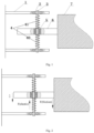
Fig. 1 is a structural schematic diagram of a guide wheel device in an embodiment; -
Fig. 2 is a schematic diagram of stress on a guide wheel in an embodiment; and -
Fig. 3 is a schematic diagram of stress-bearing movement of a guide wheel in an embodiment when ascending with a car body. - The present invention will be further described below in combination with specific embodiments. Wherein the drawings are only used for exemplary description, are only schematic diagrams rather than physical diagrams, and shall not be understood as a limitation to the present patent. In order to better illustrate the embodiments of the present invention, some components in the drawings may be omitted, scaled up or scaled down, and do not reflect actual product sizes. It should be understandable for those skilled in the art that some well-known structures and description thereof in the drawings may be omitted.
- As shown in
Fig. 1 , the embodiment provides a guide wheel device, comprising abase 1, a slewing bearing 2, awheel shaft 3,springs 4, a linear bearing 5 and aguide wheel 6. The linear bearing 5 is arranged in theguide wheel 6 and sheathed on thewheel shaft 3, thewheel shaft 3 and thebase 1 are connected by the slewing bearing 2, thesprings 4 are sheathed on thewheel shaft 3 on both sides of theguide wheel 6 and include alower spring 40 and anupper spring 41, both sides of theguide wheel 6 are respectively connected to one side of theupper spring 41 and one side of thelower spring 40, and thebase 1 is fixedly arranged on a car body. - The
lower spring 40 is naturally in a compressed state, and the elastic force F(elastic) of thelower spring 40 is equal to the gravity G of theguide wheel 6. - The
guide wheel 6 always keeps in contact with atrack 7 during operation. - In the embodiment, the linear bearing 5 is a slewing linear bearing.
- When the guide wheel device is in the initial state, the
guide wheel 6 is located in the middle of thewheel shaft 3. - In the embodiment, the length of the
upper spring 41 is smaller than that of thelower spring 40. - As shown in
Figs 1 and 2 , the guide method of the present invention is as follows:
A friction force F(friction) exists between theguide wheel 6 and thetrack 7, theguide wheel 6 itself has a gravity G, and thesprings 4 have elastic forces F(elastic); the value of F(friction) will fluctuate up and down due to track manufacturing errors and car body shaking in the operation process; as the guide wheel device will move up or down, the direction of F(friction) will be downward or upward. - In the initial state, G=F(elastic), and the
guide wheel 6 remains in the middle of the wheel shaft. - When the guide wheel device ascends or descends, the elastic forces F(elastic) become greater, but F(elastic)<G+F(friction), so the
guide wheel 6 will move on the wheel shaft. - When the car body shakes in the operation process and results in F(friction) reduction, if F(elastic)>G+F(friction), the
guide wheel 6 will move to the initial state. - When the
guide wheel 6 leaves the track, F(friction) is 0, and F(elastic)>G+F(friction), so theguide wheel 6 will move to the initial state. - As shown in
Figs 1 and3 , the operating mode of the present invention is as follows:
When the guide wheel device ascends with the car body, as the sum of the friction force between theguide wheel 6 and thetrack 7 and the gravity of theguide wheel 6 is greater than the elastic forces of thesprings 4, theguide wheel 6 moves downward gradually with thelinear bearing 5 to compress thelower spring 40, which ensures that the contact position between theguide wheel 6 and thetrack 7 remains unchanged in the vertical direction; when the pressure between thetrack 7 and theguide wheel 6 is reduced or eliminated, theguide wheel 6 is pushed by the elastic force of thelower spring 40 to move upward in the vertical direction on thetrack 7; in the upward movement process, theguide wheel 6 gradually comes into contact with thetrack 7 again and generates a friction force; and the cycle is repeated. - When the guide wheel device descends with the car body, as the friction force between the
guide wheel 6 and thetrack 7 is greater than the elastic forces of thesprings 4, theguide wheel 6 moves upward gradually with thelinear bearing 5 to compress theupper spring 41, which ensures that the contact position between theguide wheel 6 and thetrack 7 remains unchanged in the vertical direction; when the pressure between thetrack 7 and theguide wheel 6 is reduced or eliminated, theguide wheel 6 is pushed by the elastic force of theupper spring 41 to move downward in the vertical direction on thetrack 7; in the downward movement process, theguide wheel 6 gradually comes into contact with thetrack 7 again and generates a friction force; and the cycle is repeated. - The embodiment can meet the requirement that a guide wheel moves perpendicular to the rotation direction of wheels, and the guide wheel can either rotate on a horizontal plane or move up and down perpendicular to the horizontal plane;
Apparently, the above embodiment is only an example made for clearly describing the present invention. - For those ordinary skilled in the art, other variations or changes in other forms can also be made based on the above description.
Claims (4)
- A maglev train guide method, comprising:arranging a guide wheel device with springs (4) and a linear bearing (5), wherein the guide wheel device comprises a base (1), a slewing bearing (2), a wheel shaft (3) and a guide wheel (6), wherein the linear bearing (5) is arranged in the guide wheel (6) and sheathed on the wheel shaft (3), the wheel shaft (3) and the base (1) are connected by the slewing bearing, the springs (4) are sheathed on the wheel shaft (3) on both sides of the guide wheel (6) and include a lower spring (40) and an upper spring (41), both sides of the guide wheel (6) are respectively connected to one side of the upper spring (41) and one side of the lower spring (40), and the base (1) is fixedly arranged on a car body, wherein the lower spring is naturally in a compressed state, and the elastic force F(elastic) of the lower spring is equal to the gravity G of the guide wheel, and the linear bearing is a slewing linear bearing, whereina friction force F(friction) exists between the guide wheel (6) and a track (7), the guide wheel (6) itself has a gravity G, and the springs (4) have elastic forces F(elastic); the value of F(friction) will fluctuate up and down due to track (7) manufacturing errors and car body shaking in the operation process; as the guide wheel device will move up or down, the direction of F(friction) will be downward or upward;in an initial state, G=F(elastic), and the guide wheel (6) remains in the middle of the wheel shaft (3);when the guide wheel device ascends with the car body, sum of the friction force between the guide wheel (6) and the track (7) and the gravity of the guide wheel (6) is greater than the elastic forces of the springs (4), the guide wheel (6) moves downward gradually with the linear bearing (5) to compress the lower spring (40), the contact position between the guide wheel (6) and the track (7) remains unchanged in the vertical direction; when the pressure between the track (7) and the guide wheel (6) is reduced or eliminated, the guide wheel (6) is pushed by the elastic force of the lower spring (40) to move upward in the vertical direction on the track (7); in the upward movement process, the guide wheel (6) gradually comes into contact with the track (7) again and generates a friction force; and the cycle is repeated;when the guide wheel device descends with the car body, the friction force between the guide wheel (6) and the track (7) is greater than the elastic forces of the springs (4), the guide wheel (6) moves upward gradually with the linear bearing (5) to compress the upper spring (41), the contact position between the guide wheel (6) and the track (7) remains unchanged in the vertical direction; when the pressure between the track (7) and the guide wheel (6) is reduced or eliminated, the guide wheel (69 is pushed by the elastic force of the upper spring (41) to move downward in the vertical direction on the track (7); in the downward movement process, the guide wheel (6) gradually comes into contact with the track (7) again and generates a friction force; and the cycle is repeated;when the car body shakes in the operation process and results in F(friction) reduction, if F(elastic)>G+F(friction), the guide wheel will move to the initial state;when the guide wheel (6) leaves the track (7), F(friction) is 0, and F(elastic)>G+F(friction), so the guide wheel (6) will move to the initial state.
- A guide wheel device comprising a base (1), a slewing bearing (2), a wheel shaft (3), springs (4), a linear bearing (5) and a guide wheel (6), wherein the linear bearing (5) is arranged in the guide wheel (6) and sheathed on the wheel shaft (3), the wheel shaft (3) and the base (1) are connected by the slewing bearing (2), the springs (4) are sheathed on the wheel shaft (3) on both sides of the guide wheel (6) and include a lower spring (40) and an upper spring (41), both sides of the guide wheel (6) are respectively connected to one side of the upper spring (41) and one side of the lower spring (40), and the base (1) is fixedly arranged on a car body, characterized in that the lower spring (40) is naturally in a compressed state, and the elastic force F(elastic) of the lower spring (40) is equal to the gravity G of the guide wheel (6), and the linear bearing (5) is a slewing linear bearing; and in that the guide wheel device is configured to carry out the method of claim 1.
- The guide wheel device according to claim 2, wherein the length of the upper spring (41) is smaller than that of the lower spring (40).
- The guide wheel device according to claim 2, wherein the guide wheel (6) is configured such that: the guide wheel (6) can either rotate on a horizontal plane or move up and down perpendicular to the horizontal plane.
Applications Claiming Priority (2)
| Application Number | Priority Date | Filing Date | Title |
|---|---|---|---|
| CN201911035850.4A CN110722993B (en) | 2019-10-29 | 2019-10-29 | Magnetic suspension train guiding method and guide wheel device |
| PCT/CN2020/114155 WO2021082750A1 (en) | 2019-10-29 | 2020-09-09 | Maglev train guiding method and guide wheel device |
Publications (4)
| Publication Number | Publication Date |
|---|---|
| EP4052950A1 EP4052950A1 (en) | 2022-09-07 |
| EP4052950A4 EP4052950A4 (en) | 2024-01-10 |
| EP4052950B1 true EP4052950B1 (en) | 2025-02-26 |
| EP4052950C0 EP4052950C0 (en) | 2025-02-26 |
Family
ID=69222392
Family Applications (1)
| Application Number | Title | Priority Date | Filing Date |
|---|---|---|---|
| EP20882183.5A Active EP4052950B1 (en) | 2019-10-29 | 2020-09-09 | Maglev train guiding method and guide wheel device |
Country Status (4)
| Country | Link |
|---|---|
| EP (1) | EP4052950B1 (en) |
| CN (1) | CN110722993B (en) |
| ES (1) | ES3021866T3 (en) |
| WO (1) | WO2021082750A1 (en) |
Families Citing this family (1)
| Publication number | Priority date | Publication date | Assignee | Title |
|---|---|---|---|---|
| CN110722993B (en) * | 2019-10-29 | 2022-12-23 | 株洲时代新材料科技股份有限公司 | Magnetic suspension train guiding method and guide wheel device |
Citations (1)
| Publication number | Priority date | Publication date | Assignee | Title |
|---|---|---|---|---|
| CN108757894A (en) * | 2018-08-29 | 2018-11-06 | 潍坊市华玉塑料机械有限公司 | The tensioner sprocket wheel of adaptive chain drive |
Family Cites Families (19)
| Publication number | Priority date | Publication date | Assignee | Title |
|---|---|---|---|---|
| DE2711994C3 (en) * | 1977-03-18 | 1980-05-14 | Goetz Dipl.-Phys. 8136 Percha Heidelberg | Vehicle that is held opposite a track with the aid of an attracting magnetic device and an additional force device |
| US4913059A (en) * | 1988-02-25 | 1990-04-03 | Railway Technical Research Institute | Levitation, propulsion and guidance mechanism for inductive repulsion-type magnetically levitated railway |
| JPH05208730A (en) * | 1992-10-15 | 1993-08-20 | Daifuku Co Ltd | Cargo conveying equipment |
| JP3152775B2 (en) * | 1992-12-07 | 2001-04-03 | 株式会社東芝 | Magnetic levitation device |
| JPH079804A (en) * | 1993-06-29 | 1995-01-13 | Toogo:Kk | Wheel device for orbital play vehicle |
| ES2220225B1 (en) * | 2003-05-27 | 2006-01-16 | Roberto Blanco Montejo | INTEGRAL TRAIN GUIDE SYSTEM, "CENTRAL GUIDE ROLLING BOX" (R.B. "ROLLING BOX SYSTEM"). |
| CN100391770C (en) * | 2005-11-01 | 2008-06-04 | 李岭群 | Structural technology system of pathway and vehicle in magnetic suspension on grooved rail |
| WO2012061995A1 (en) * | 2010-11-12 | 2012-05-18 | Lu Yong | Suspension vehicle |
| CN103175894B (en) * | 2013-02-06 | 2015-06-24 | 合肥超科电子有限公司 | Manual wheel type steel rail ultrasonic flaw detection car |
| CN204211361U (en) * | 2014-09-29 | 2015-03-18 | 尹时中 | A kind of axial elasticity self adaptation road wheel |
| CN104670041A (en) * | 2015-03-10 | 2015-06-03 | 南车株洲电力机车有限公司 | Magnetic suspension railcar and running mechanism thereof |
| CN105128616B (en) * | 2015-08-18 | 2017-08-29 | 朗信通(天津)机器人科技有限公司 | A kind of auto-guider |
| CN106476832B (en) * | 2016-12-07 | 2018-12-14 | 中车株洲电力机车有限公司 | A kind of magnetic levitation track vehicle and its bogie |
| CN106985875B (en) * | 2016-12-29 | 2019-04-19 | 比亚迪股份有限公司 | Rail vehicles and guide wheel arrangements for rail vehicles |
| CN108394310B (en) * | 2018-01-22 | 2023-08-29 | 同济大学 | A drive and protection device for a linear motor of a medium-low speed maglev train |
| CN208069680U (en) * | 2018-03-27 | 2018-11-09 | 中车唐山机车车辆有限公司 | A kind of guider and magnetic suspension train |
| CN208576998U (en) * | 2018-07-18 | 2019-03-05 | 北京京东尚科信息技术有限公司 | A kind of guide frame and shuttle |
| CN208666175U (en) * | 2018-07-23 | 2019-03-29 | 北京京东尚科信息技术有限公司 | Attachment device, tourelle and automated guided vehicle |
| CN110722993B (en) * | 2019-10-29 | 2022-12-23 | 株洲时代新材料科技股份有限公司 | Magnetic suspension train guiding method and guide wheel device |
-
2019
- 2019-10-29 CN CN201911035850.4A patent/CN110722993B/en active Active
-
2020
- 2020-09-09 EP EP20882183.5A patent/EP4052950B1/en active Active
- 2020-09-09 ES ES20882183T patent/ES3021866T3/en active Active
- 2020-09-09 WO PCT/CN2020/114155 patent/WO2021082750A1/en not_active Ceased
Patent Citations (1)
| Publication number | Priority date | Publication date | Assignee | Title |
|---|---|---|---|---|
| CN108757894A (en) * | 2018-08-29 | 2018-11-06 | 潍坊市华玉塑料机械有限公司 | The tensioner sprocket wheel of adaptive chain drive |
Also Published As
| Publication number | Publication date |
|---|---|
| WO2021082750A1 (en) | 2021-05-06 |
| CN110722993A (en) | 2020-01-24 |
| EP4052950A1 (en) | 2022-09-07 |
| ES3021866T3 (en) | 2025-05-27 |
| EP4052950A4 (en) | 2024-01-10 |
| CN110722993B (en) | 2022-12-23 |
| EP4052950C0 (en) | 2025-02-26 |
Similar Documents
| Publication | Publication Date | Title |
|---|---|---|
| CN107190595B (en) | Permanent magnet suspension train track system | |
| KR101630783B1 (en) | Magnetic levitation system comprising propulsion electromagnet having guiding function | |
| CN106143205B (en) | A kind of coil type permanent-magnet electric levitation device for magnetic-levitation train | |
| CN103958263B (en) | Drive systems for transport systems | |
| CN111373097B (en) | Permanent magnetic suspension train adopting passive low-frequency electromagnetic stabilization | |
| CA2437223A1 (en) | Monorail system | |
| CN102653247A (en) | Blade-adjusted-type permanent magnetic suspension technology | |
| CN212243340U (en) | Suspension type magnetic suspension traffic system | |
| CN112078376B (en) | A kind of permanent magnet maglev train steering control method and system | |
| US11167647B2 (en) | Magnetic suspension for a vehicle | |
| CN108394312A (en) | A kind of magnetic suspension train | |
| CN101877563B (en) | A magnetic resistance type magnetic levitation device | |
| EP4052950B1 (en) | Maglev train guiding method and guide wheel device | |
| US12103569B2 (en) | Vacuum pipeline magnetic levitation conveying device | |
| CN109177740B (en) | Structure of running part of a suspended maglev train | |
| CN1321848C (en) | High speed rail vehicle capable of adjusting pressure on ground | |
| US4941406A (en) | Magnetic and aerodynamic levitation vehicle | |
| CN1107606C (en) | Magnetic floated power compartment | |
| CN219078238U (en) | Magnetic auxiliary brake device for track | |
| CN201560056U (en) | Magnetic suspension wheelless rail type crane | |
| CN210337903U (en) | Track system for magnetic suspension train | |
| KR20120004865A (en) | Maglev Transfer System with Spring | |
| CN2303755Y (en) | Suspension train for entertainment | |
| CN117465227B (en) | Passenger and cargo permanent magnet suspension transportation system driven by distributed wheel type permanent magnet motor | |
| CN205132859U (en) | Directly drive elevator system |
Legal Events
| Date | Code | Title | Description |
|---|---|---|---|
| STAA | Information on the status of an ep patent application or granted ep patent |
Free format text: STATUS: THE INTERNATIONAL PUBLICATION HAS BEEN MADE |
|
| PUAI | Public reference made under article 153(3) epc to a published international application that has entered the european phase |
Free format text: ORIGINAL CODE: 0009012 |
|
| STAA | Information on the status of an ep patent application or granted ep patent |
Free format text: STATUS: REQUEST FOR EXAMINATION WAS MADE |
|
| 17P | Request for examination filed |
Effective date: 20220321 |
|
| AK | Designated contracting states |
Kind code of ref document: A1 Designated state(s): AL AT BE BG CH CY CZ DE DK EE ES FI FR GB GR HR HU IE IS IT LI LT LU LV MC MK MT NL NO PL PT RO RS SE SI SK SM TR |
|
| DAV | Request for validation of the european patent (deleted) | ||
| DAX | Request for extension of the european patent (deleted) | ||
| A4 | Supplementary search report drawn up and despatched |
Effective date: 20231208 |
|
| RIC1 | Information provided on ipc code assigned before grant |
Ipc: B61B 13/08 20060101ALI20231204BHEP Ipc: B60L 13/08 20060101ALI20231204BHEP Ipc: B61F 9/00 20060101ALI20231204BHEP Ipc: B60L 13/06 20060101AFI20231204BHEP |
|
| GRAP | Despatch of communication of intention to grant a patent |
Free format text: ORIGINAL CODE: EPIDOSNIGR1 |
|
| STAA | Information on the status of an ep patent application or granted ep patent |
Free format text: STATUS: GRANT OF PATENT IS INTENDED |
|
| INTG | Intention to grant announced |
Effective date: 20241115 |
|
| GRAS | Grant fee paid |
Free format text: ORIGINAL CODE: EPIDOSNIGR3 |
|
| GRAA | (expected) grant |
Free format text: ORIGINAL CODE: 0009210 |
|
| STAA | Information on the status of an ep patent application or granted ep patent |
Free format text: STATUS: THE PATENT HAS BEEN GRANTED |
|
| AK | Designated contracting states |
Kind code of ref document: B1 Designated state(s): AL AT BE BG CH CY CZ DE DK EE ES FI FR GB GR HR HU IE IS IT LI LT LU LV MC MK MT NL NO PL PT RO RS SE SI SK SM TR |
|
| REG | Reference to a national code |
Ref country code: GB Ref legal event code: FG4D |
|
| REG | Reference to a national code |
Ref country code: CH Ref legal event code: EP |
|
| REG | Reference to a national code |
Ref country code: DE Ref legal event code: R096 Ref document number: 602020046971 Country of ref document: DE |
|
| REG | Reference to a national code |
Ref country code: IE Ref legal event code: FG4D |
|
| U01 | Request for unitary effect filed |
Effective date: 20250313 |
|
| U07 | Unitary effect registered |
Designated state(s): AT BE BG DE DK EE FI FR IT LT LU LV MT NL PT RO SE SI Effective date: 20250403 |
|
| REG | Reference to a national code |
Ref country code: ES Ref legal event code: FG2A Ref document number: 3021866 Country of ref document: ES Kind code of ref document: T3 Effective date: 20250527 |
|
| PG25 | Lapsed in a contracting state [announced via postgrant information from national office to epo] |
Ref country code: RS Free format text: LAPSE BECAUSE OF FAILURE TO SUBMIT A TRANSLATION OF THE DESCRIPTION OR TO PAY THE FEE WITHIN THE PRESCRIBED TIME-LIMIT Effective date: 20250526 |
|
| PG25 | Lapsed in a contracting state [announced via postgrant information from national office to epo] |
Ref country code: PL Free format text: LAPSE BECAUSE OF FAILURE TO SUBMIT A TRANSLATION OF THE DESCRIPTION OR TO PAY THE FEE WITHIN THE PRESCRIBED TIME-LIMIT Effective date: 20250226 |
|
| PG25 | Lapsed in a contracting state [announced via postgrant information from national office to epo] |
Ref country code: NO Free format text: LAPSE BECAUSE OF FAILURE TO SUBMIT A TRANSLATION OF THE DESCRIPTION OR TO PAY THE FEE WITHIN THE PRESCRIBED TIME-LIMIT Effective date: 20250526 Ref country code: IS Free format text: LAPSE BECAUSE OF FAILURE TO SUBMIT A TRANSLATION OF THE DESCRIPTION OR TO PAY THE FEE WITHIN THE PRESCRIBED TIME-LIMIT Effective date: 20250626 |
|
| PG25 | Lapsed in a contracting state [announced via postgrant information from national office to epo] |
Ref country code: HR Free format text: LAPSE BECAUSE OF FAILURE TO SUBMIT A TRANSLATION OF THE DESCRIPTION OR TO PAY THE FEE WITHIN THE PRESCRIBED TIME-LIMIT Effective date: 20250226 |
|
| PG25 | Lapsed in a contracting state [announced via postgrant information from national office to epo] |
Ref country code: GR Free format text: LAPSE BECAUSE OF FAILURE TO SUBMIT A TRANSLATION OF THE DESCRIPTION OR TO PAY THE FEE WITHIN THE PRESCRIBED TIME-LIMIT Effective date: 20250527 |
|
| U20 | Renewal fee for the european patent with unitary effect paid |
Year of fee payment: 6 Effective date: 20250703 |
|
| PG25 | Lapsed in a contracting state [announced via postgrant information from national office to epo] |
Ref country code: SM Free format text: LAPSE BECAUSE OF FAILURE TO SUBMIT A TRANSLATION OF THE DESCRIPTION OR TO PAY THE FEE WITHIN THE PRESCRIBED TIME-LIMIT Effective date: 20250226 |
|
| PG25 | Lapsed in a contracting state [announced via postgrant information from national office to epo] |
Ref country code: CZ Free format text: LAPSE BECAUSE OF FAILURE TO SUBMIT A TRANSLATION OF THE DESCRIPTION OR TO PAY THE FEE WITHIN THE PRESCRIBED TIME-LIMIT Effective date: 20250226 |
|
| PG25 | Lapsed in a contracting state [announced via postgrant information from national office to epo] |
Ref country code: SK Free format text: LAPSE BECAUSE OF FAILURE TO SUBMIT A TRANSLATION OF THE DESCRIPTION OR TO PAY THE FEE WITHIN THE PRESCRIBED TIME-LIMIT Effective date: 20250226 |
|
| PLBE | No opposition filed within time limit |
Free format text: ORIGINAL CODE: 0009261 |
|
| STAA | Information on the status of an ep patent application or granted ep patent |
Free format text: STATUS: NO OPPOSITION FILED WITHIN TIME LIMIT |
|
| REG | Reference to a national code |
Ref country code: CH Ref legal event code: L10 Free format text: ST27 STATUS EVENT CODE: U-0-0-L10-L00 (AS PROVIDED BY THE NATIONAL OFFICE) Effective date: 20260107 |
|
| PGFP | Annual fee paid to national office [announced via postgrant information from national office to epo] |
Ref country code: ES Payment date: 20251023 Year of fee payment: 6 |
|
| 26N | No opposition filed |
Effective date: 20251127 |
|
| REG | Reference to a national code |
Ref country code: CH Ref legal event code: H13 Free format text: ST27 STATUS EVENT CODE: U-0-0-H10-H13 (AS PROVIDED BY THE NATIONAL OFFICE) Effective date: 20260425 |