EP4052602B1 - Helm mit mikrofontragearm - Google Patents
Helm mit mikrofontragearm Download PDFInfo
- Publication number
- EP4052602B1 EP4052602B1 EP22158503.7A EP22158503A EP4052602B1 EP 4052602 B1 EP4052602 B1 EP 4052602B1 EP 22158503 A EP22158503 A EP 22158503A EP 4052602 B1 EP4052602 B1 EP 4052602B1
- Authority
- EP
- European Patent Office
- Prior art keywords
- arm
- shell
- helmet
- pin
- head
- Prior art date
- Legal status (The legal status is an assumption and is not a legal conclusion. Google has not performed a legal analysis and makes no representation as to the accuracy of the status listed.)
- Active
Links
Images


Classifications
-
- A—HUMAN NECESSITIES
- A42—HEADWEAR
- A42B—HATS; HEAD COVERINGS
- A42B3/00—Helmets; Helmet covers ; Other protective head coverings
- A42B3/04—Parts, details or accessories of helmets
- A42B3/30—Mounting radio sets or communication systems
-
- A—HUMAN NECESSITIES
- A42—HEADWEAR
- A42B—HATS; HEAD COVERINGS
- A42B3/00—Helmets; Helmet covers ; Other protective head coverings
- A42B3/32—Collapsible helmets; Helmets made of separable parts ; Helmets with movable parts, e.g. adjustable
- A42B3/326—Helmets with movable or separable chin or jaw guard
Definitions
- the present invention relates to the field of protective helmets, in particular to a protective helmet for motor sports with an integrated audio communication system.
- Protective helmets are known which comprise a rigid shell to be worn on the head to protect the same and which may or may not be provided with an eye visor.
- the helmets may have a rigid portion, called chin guard, extending from the shell to protect the chin and mouth, in which case they are known as full-face helmets.
- Helmets without a chin guard are commonly known as open-face helmets or jet helmets.
- Some helmets especially those intended for sporting use, have an integrated audio communication system which enables the person wearing the helmet to communicate with other passengers on the vehicle (intercom) or with persons on the ground (telephone and/or radio system).
- the audio communication system comprises at least one loudspeaker placed in the shell, substantially aligned with the ear, and a microphone.
- the microphone is supported by a flexible stem extending from the shell towards the mouth of the user.
- open helmets are known in which the microphone is integrated in a rigid arm extending from a front portion of the shell in the form of a chin guard to face the user's mouth with its free end.
- This configuration is advantageous because, for example in carbon or fibreglass helmets, the arm is moulded together with the shell and therefore has a corresponding rigidity, as well as an aesthetic impact consistent with the rest of the helmet.
- the rigid arm in the form of a chin guard also provides a comfortable grip for the user, who can carry the helmet by holding it by the arm.
- helmets have some drawbacks.
- the helmet has a rigid arm in the form of a chin guard, in the event of an accident it has to be treated in particular situations like a full-face helmet, i.e. it has to be completely removed in order to free the wearer's face and provide the rescuers with freedom of intervention on the main airways (mouth and nose).
- WO 2020/230102 on which the preamble of independent claim 1 is based, discloses a helmet having a rigid arm bearing at its distal end a microphone of an integrated audio communication system, wherein the rigid arm is made as a separate piece from the shell and is releasably connected thereto by a releasable coupling system, and wherein the helmet further comprises retaining means to prevent accidental opening of the coupling system.
- the coupling system of the helmet known from said prior art document, with the associated retaining means is rather complex, bulky and heavy.
- the retaining means of the helmet known from said prior art document are not capable of safely and reliably preventing accidental disconnection of the arm.
- this prior art document does not contain any teaching on how to realize the quick electrical connection of the microphone, which is essential to enable effective quick coupling of the arm.
- the invention is based on the idea of using, as retaining means to prevent accidental opening of the reversible coupling means, a screw fixed to the arm and protruding inwards with a head thereof, an elastically flexible element fixed to the shell below the attachment portion of the shell itself and having a hole in which the head of the screw engages, in the condition of attachment of the arm to the shell, and a release member operable by the user to elastically deform the elastically flexible element so as to allow the head of the screw to disengage from the hole.
- the coupling system is simpler, less bulky and lighter, but at the same time safer and more effective, than the prior art.
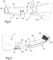
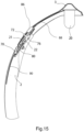
- a helmet with an integrated audio communication system is generally indicated 1.
- the helmet 1 comprises a shell 2 for protecting a user's head. From a lateral portion of the shell 2 a rigid arm 3 extends in the form of a chin guard, in such a manner that a distal end 3a of the arm 3 is located, in use, near the mouth of the user. A microphone 20 of the audio communication system of the helmet 1 is supported on the distal end 3a of the arm 3.
- the arm 3 is detachably connected to the shell 2 by releasable coupling means.
- the arm 3 is provided, at a proximal end 3b thereof, with a first coupling member, preferably made as a male coupling member, arranged to releasably engage with a second coupling member, preferably made as a female coupling member, provided on the shell 2.
- the first coupling member is formed by a protruding tooth 30 extending from the proximal end 3b of the arm 3.
- An attachment portion 2a for attachment of the arm 3 extends from the lateral portion of the shell 2.
- the aforementioned second coupling member is provided on the attachment portion 2a.
- the second coupling member comprises a seat 10 into which the protruding tooth 30 of the arm 3 can be inserted.
- the attachment portion 2a is offset with respect to the adjacent outer surface, indicated at 2b, of the lateral portion of the shell 2, that is, it defines an area of depression.
- a step 2c is thus formed between the outer surface 2b and the attachment portion 2a of the shell 2.
- the seat 10 is provided in the region of the step 2c.
- the arm 3 is shaped in such a way that, when it is connected to the attachment portion 2a of the shell 2, an outer face 3c thereof is flush with the adjacent outer surface 2b of the lateral portion of the shell 2.
- the protruding tooth 30 is inserted into the seat 10 and is housed below the outer surface 2b of the lateral portion of the shell 2.
- the attachment portion 2a is made in one piece with the shell 2.
- the attachment portion 2a may be made separately from the shell 2 and subsequently connected to the shell by techniques that are known in the art and therefore are not described in detail herein.
- the electrical connection of the audio communication system is also carried out, if such a connection is obtained by means of an electrical connector.
- an electrical connector On an inner face 3d of the arm 3, in the region of the proximal end 3b, a connector 21 for the microphone 20 is placed.
- a corresponding connector 22 for the loudspeaker is associated with the attachment portion 2a of the shell 2.
- the connection between the connectors 21 and 22 makes the electrical connection of the microphone 20 to the remaining part of the intercom or electronics of the audio communication system.
- connection via electrical connectors a connection via magnetic contact connectors or other types of connectors may be envisaged.
- connection, and in general the cables of the communication system are concealed by the internal coating of the shell 2 and of the arm 3, which is made in a traditional way (e.g. in foam rubber or generically padded). If necessary, a keypad for controlling the communication system, as well as a battery, may also be arranged on the inner face 3d of the arm 3.
- the arm 3 may accommodate, in addition to the microphone, all the electronics of the communication system, i.e. a control keypad, a circuit board and a battery, if any.
- Retaining means which will be described in detail below, are provided to prevent unintentional disengagement of the aforementioned coupling means, and thus disconnection of the arm 3 from the shell 2.
- the retaining means comprise a pin integral with, and protruding from, the attachment portion 2a of the shell 2.
- the pin includes a head inserted into a corresponding hole made in the arm 3.
- a locking member is mounted on the arm 3 in the region of the hole to cooperate with the head of the pin.
- the locking member is movable between a closed position, in which it retains the head of the pin, thereby preventing the arm 3 from being detached from the shell 2, and an open position, in which it disengages from the head of the pin, thereby allowing the arm 3 to be detached from the shell 2.
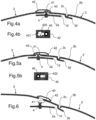
- the pin in a first embodiment of the retaining means, shown in Figures 4a to 6 , has a head 40.
- a hole 41 for the head 40 of the pin 4 is made on the arm 3, so that in the condition of attachment of the arm 3 to the shell 2 the head 40 of the pin 4 protrudes through the hole 41 on the side of the outer face 3c of the arm 3.
- a slider 42 operates in a sliding manner, which slider has a slotted seat 420 with an enlarged end 421 to allow the head 40 to extend therethrough and a section of reduced width 422 such as to allow the sliding engagement of the stem of the pin 4 but prevent the head 40 to pass therethrough.
- the slider 42 is therefore movable between the aforementioned closed position ( Figures 4a and 4b ), in which the head 40 of the pin 4 is in the region of the section 422 of the slotted seat 420 and is therefore constrained to the slider 42, so that the arm 3 cannot be detached from the attachment portion 2a of the shell 2, and the aforementioned open position ( Figures 5a and 5b ), in which the head 40 of the pin 4 is in the region of the enlarged end 421 of the slotted seat 420 and is therefore free to protrude from the hole 41, thereby allowing the arm 3 to be detached from the attachment portion 2a of the shell 2 (as shown in Figure 6 ).
- the slider 42 may be provided with a biasing spring (not shown) which opposes its sliding and forces the slider to return to the closed position in case to external release force is applied.
- the pin is integral with the attachment portion 2a of the shell 2 and protrudes therefrom outwardly with a head 50 that fits into a corresponding hole (not shown) in the arm 3.
- a slider 52 which is hinged on the arm 3 for rotation about a pivot point P spaced from the hole.
- the slider 52 has a slotted seat 520 comprising an enlarged end 521 of a size such as to allow the head 50 to extend therethrough and a section 522 with a reduced width which allows the stem of the pin 5 to slidably extend therethrough, but prevents the passage of the head 50.
- the pin 5 can be disengaged from the hole of the arm 5, and the arm 3 can thus be detached from the attachment portion 2a of the shell 2, while in any other position of the slider 52 (closed position, as shown in Figure 7a ) the head 50 of the pin 5 is in the region of the section 522 of reduced width of the slotted seat 520, so that the pin 5 cannot be disengaged from the hole of the arm 5, with the consequence that the arm 5 cannot be detached from the attachment portion 2a of the shell 2.
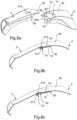
- Figures 8a to 8c show a third embodiment of the retaining means.
- the arm 3 has a slotted seat 60 in which a pin 61 is slidably engaged.
- the pin 61 includes a first head 610, facing outwards, having a diameter greater than the width of the slotted seat 60, and a second head 612, facing inwards, having the same diameter.
- a shaped housing 62 is formed on the attachment portion 2a, comprising an enlarged end 620 of such a size as to allow passage of the second head 612 of the pin 61 and a section 621 of reduced size that allows sliding engagement of the stem of the pin 61 but prevents the passage of the second head 612.
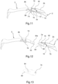
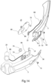
- the releasable connection between the arm 3 and the attachment portion 2a of the shell 2 is obtained by engagement between a first coupling member of the arm, which also in this case is formed by a protruding tooth 30, and a second coupling member of the attachment portion, which also in this case is formed by a seat 10.
- the protruding tooth 30 has a fork shape, with a pair of prongs 30a between which, in the coupled condition ( Figure 11 ), a pin 70 arranged on the inner side of the shell 2, near the seat 10, is inserted.
- the engagement of the pin 70 between the two prongs 30a of the protruding tooth 30 ensures a more stable connection between the arm 3 and the shell 2, in particular by preventing the arm from rocking up and down once it is coupled to the shell.
- suitable retaining means prevent accidental disconnection of the arm from the shell.
- the retaining means include, on the side of the arm 3, a screw 72 attached to the arm 3 and projecting inwards. Numerals 74 and 76 denote the stem and head of the screw 72, respectively.
- the retaining means further include, on the side of the shell 2, a slotted seat 78 provided at the free end of the attachment portion 2a and an elastically flexible element 80 fixed, for example by screws 82, to the shell 2 below the attachment portion 2a.
- the stem 74 of the screw 72 engages in the slotted seat 78 of the attachment portion 2a, while the head 76 of the screw 72 engages in a hole 84 provided in the elastically flexible element 80.
- the pin 70 is mounted on the elastically flexible element 80, so that, when the pin 70 is inserted between the two prongs 30a of the protruding tooth 30, the arm 3 is self-centred on the elastically flexible element 80 and thus the distance between the pin 70 and the hole 84 of the elastically flexible element 80 is defined on the element 80 itself, instead of depending on the tolerances between the position of the pin 70 on the shell 2 and the fixing position of the elastically flexible element 80.
- the elastically flexible element 80 can be made of plastic material and also form the pin 70 in one piece.
- the arm 3 is provided with a release button 86 which, when pressed, acts on the elastically flexible member 80 causing it to flex downwards until the head 76 of the screw 72 is disengaged from the hole 84.
- the release button 86 is preferably made of an elastically deformable material, for example rubber or silicone, so that it is normally held in a raised position, in which it does not act on the elastically flexible element 80.
- the release button 86 might be associated with elastic means acting on the button itself so as to keep it normally in a raised position.
- the fact that the release button 86 is made of rubber or silicone makes it possible to reduce the number of components of the helmet which are made of plastic, thus reducing both the risks in case of fire and the risks of breakage.
- the electrical connection between the microphone 20 carried by the arm 3 and the remaining part of the audio communication system of the helmet 1 is ensured by the connection between the connectors 21 and 22 associated with the microphone 20 and the loudspeaker, respectively.
- the connector 21 is mounted on an inner face 3d of the arm 3, at the proximal end 3b of the arm, and is connected by means of a cable 88 to the microphone 20, while the connector 22 is mounted on the attachment portion 2a of the shell 2 and is connected by means of a cable 90 to the loudspeaker (not shown) located in the shell 2.
- the two connectors 21 and 22 are configured to make a quick electrical connection when the arm 3 is coupled to the shell 2. When the arm 3 is disconnected from the shell 2, however, the two connectors 21 and 22 are disconnected from each other, thereby interrupting the connection between the microphone 20 carried by the arm 3 and the loudspeaker mounted in the shell 2.
- the arm and the shell are made of carbon or fibreglass, which allows to obtain a lightweight helmet.
- the arm might alternatively be made of plastic, SMC (Sheet Moulding Compound) or C-SMC (Carbon-Sheet Moulding Compound).
- the solution described allows the arm to be fitted/removed easily. This is an advantage also during rescue operations requiring the removal of the helmet or, in any case, the need for rapid access of medical personnel to the user's airways.
- the arm is firmly in position once it has been mounted, so that the helmet can be transported by gripping the arm.
- the retaining means also ensure that the arm is firmly attached to the shell, preventing its unintentional disconnection.
- a double action i.e. pressing the release button and pulling the arm, is required to disconnect the arm from the shell allows to eliminate, or at least greatly reduce, the risk of unintentional disconnection of the arm in the event of a collision with external parts.
Landscapes
- Helmets And Other Head Coverings (AREA)
Claims (9)
- Helm (1) mit einem integrierten Audiokommunikationssystem, wobei der Helm (1) eine Schale (2) zum Schutz des Kopfes eines Nutzers aufweist, wobei sich von einem seitlichen Teil der Schale (2) aus ein starrer Arm (3) als Kinnschutz erstreckt, so dass sich ein distales Ende (3a) des Armes (3) beim Gebrauch in der Nähe des Mundes des Nutzers befindet, und wobei der Arm (3) an seinem besagten distalen Ende (3a) ein Mikrofon (20) des besagten Audiokommunikationssystems trägt,wobei der Arm (3) ein von der Schale (2) getrenntes Teil ist und mittels gegenseitiger Kuppelungsmittel (30, 10) lösbar mit der Schale (2) verbunden ist, welche ein erstes Kuppelungselement (30) umfassen, das an einem proximalen Ende (3b) des Armes (3) gegenständig zu dem besagten distalen Ende (3a) vorgesehen ist, sowie ein zweites Kuppelungselement (10), das an einem Verbindungsteil (2a) der Schale (2) vorgesehen ist, undwobei der Helm (1) ferner Halteeinrichtungen (4, 42; 5, 52; 61, 62; 72, 80, 86) zur Vermeidung eines unbeabsichtigten Lösens der besagten lösbaren Kuppelungsmittel (30, 10) aufweist,dadurch gekennzeichnet, dass die besagten Halteeinrichtungen (4, 42; 5, 52; 61, 62; 72, 80, 86) eine Schraube (72) umfassen, die an dem Arm (3) befestigt ist und mit ihrem Kopf (76) nach innen übersteht, ferner ein elastisch biegbares Element (80), das an der Schale (2) unterhalb des Verbindungsteils (2a) befestigt ist und ein Loch (84) aufweist, in welches der Kopf (76) der Schraube (72) in dem Zustand der Befestigung des Arms (3) an der Schale (2) eingreift, sowie ein Freigabe-Element (86), das von dem Nutzer bedient werden kann, um das elastisch biegbare Element (80) elastisch zu verformen und so das Ausrücken des Kopfs (76) der Schraube (72) aus dem Loch (84) zu ermöglichen.
- Helm gemäß Anspruch 1, wobei das besagte erste Kuppelungselement (30) durch einen Zahn gebildet wird, der aus dem besagten proximalen Ende (3b) des Arms (3) herausragt, und wobei das besagte zweite Kuppelungselement (10) durch eine Aufnahme gebildet wird, die dazu ausgelegt ist, den besagten überstehenden Zahn aufzunehmen.
- Helm gemäß Anspruch 2, wobei das besagte erste Kuppelungselement (30) eine gabelartige Gestalt aufweist mit einem Paar von Zinken (30a), zwischen denen in dem Zustand der Befestigung des Arms (3) an der Schale (2) ein Stift (70) eingesteckt ist, wobei der besagte Stift (70) an einer Innenseite des besagten seitlichen Teils der Schale (2) angeordnet ist, nahe bei dem besagten zweiten Kuppelungselement (10).
- Helm gemäß Anspruch 3, wobei der Stift (70) in einem Stück mit dem elastisch biegbaren Element (80) ausgeformt ist.
- Helm gemäß Anspruch 4, wobei der Stift (70) und das elastisch biegbare Element (80) aus Kunststoff bestehen.
- Helm gemäß einem der vorhergehenden Ansprüche, wobei der Arm (3) so ausgelegt ist, dass in dem Zustand der Befestigung an der Schale (2) eine Außenfläche (3c) des Arms (3) bündig mit einer angrenzenden Außenfläche (2b) des besagten seitlichen Teils der Schale (2) ist.
- Helm gemäß einem der vorhergehenden Ansprüche, wobei das Audiokommunikationssystem ferner einen Lautsprecher aufweist, der in der Schale (2) an einer derartigen Position befestigt ist, dass er mit dem Ohr des Nutzers ausgerichtet ist, und wobei der Helm ferner einen ersten Anschluss (21) für das Mikrofon (20) und einen zweiten Anschluss (22) für den Lautsprecher umfasst, die an dem besagten ersten bzw. zweiten Kuppelungselement (30, 10) angeordnet sind, wobei die Verbindung des Arms (3) mit dem Verbindungsteil (2a) der Schale (2) auch zu der gegenseitigen Verbindung des besagten ersten und zweiten Anschlusses (21, 22) führt.
- Helm gemäß einem der vorhergehenden Ansprüche, wobei die Schale (2) aus Carbonfasern oder Glasfasern besteht, und wobei der Arm (3) aus Carbonfasern, Glasfasern, Kunststoff, SMC oder C-SMC besteht.
- Helm gemäß einem der vorhergehenden Ansprüche, wobei das besagte Freigabe-Element (86) aus einem elastisch verformbaren Material wie Gummi oder Silikon besteht.
Applications Claiming Priority (1)
| Application Number | Priority Date | Filing Date | Title |
|---|---|---|---|
| IT102021000004358A IT202100004358A1 (it) | 2021-02-25 | 2021-02-25 | Casco con braccetto portamicrofono |
Publications (2)
| Publication Number | Publication Date |
|---|---|
| EP4052602A1 EP4052602A1 (de) | 2022-09-07 |
| EP4052602B1 true EP4052602B1 (de) | 2023-08-16 |
Family
ID=75769902
Family Applications (1)
| Application Number | Title | Priority Date | Filing Date |
|---|---|---|---|
| EP22158503.7A Active EP4052602B1 (de) | 2021-02-25 | 2022-02-24 | Helm mit mikrofontragearm |
Country Status (2)
| Country | Link |
|---|---|
| EP (1) | EP4052602B1 (de) |
| IT (1) | IT202100004358A1 (de) |
Family Cites Families (4)
| Publication number | Priority date | Publication date | Assignee | Title |
|---|---|---|---|---|
| ITMI992366A1 (it) * | 1999-11-12 | 2001-05-14 | Ludovico Fassitelli | Casco di protezione jet aperto per uso automobilistico motociclisticoe sportivo in genere con prolungamento della parte laterale con funzio |
| ITMI20080394U1 (it) * | 2008-11-28 | 2010-05-29 | Opticos Srl | Dispositivo di fissaggio reversibile |
| JP5358725B1 (ja) * | 2012-07-02 | 2013-12-04 | 株式会社アライヘルメット | マイクロフォンの保持装置及びオープンフェースヘルメット |
| AU2020274433A1 (en) * | 2019-05-16 | 2021-12-02 | Locatelli S.P.A. | Protective helmet |
-
2021
- 2021-02-25 IT IT102021000004358A patent/IT202100004358A1/it unknown
-
2022
- 2022-02-24 EP EP22158503.7A patent/EP4052602B1/de active Active
Also Published As
| Publication number | Publication date |
|---|---|
| EP4052602A1 (de) | 2022-09-07 |
| IT202100004358A1 (it) | 2022-08-25 |
Similar Documents
| Publication | Publication Date | Title |
|---|---|---|
| JP6046613B2 (ja) | 保護ヘルメット | |
| CA2804573C (en) | Interior fittings for a protective helmet, particularly for forestry workers | |
| US4903346A (en) | Multi-part protective helmet | |
| EP3366153B1 (de) | Schutzhelm mit hochklappbarem visier/brille | |
| USRE45459E1 (en) | Protective helmet | |
| US5191882A (en) | Apparatus for enabling a strapless breathing mask to be worn without a protective helmet | |
| US10492559B1 (en) | Helmet with removable chin bar | |
| EP2536304B1 (de) | Schutzhelm | |
| US4335472A (en) | Retaining assembly for protective headgear | |
| US6912727B2 (en) | Head harness for night vision device | |
| EP4052602B1 (de) | Helm mit mikrofontragearm | |
| EP3103248B1 (de) | Adapter zur befestigung einer kopfhörervorrichtung an einem helm | |
| US11234476B2 (en) | Protective helmet, in particular motorcycle helmet, having a swivelable and removable chin part | |
| EP2775877B1 (de) | Verriegelungssystem für helmvisieradapter | |
| CN113891662A (zh) | 防护头盔 | |
| US11717046B2 (en) | Protective helmet and method for adjusting a protective helmet | |
| EP4537693A1 (de) | Schutzhelm mit aufhängungssystem | |
| WO2025078514A1 (en) | Protective helmet assembly with at least one accessory | |
| KR102441497B1 (ko) | 헬멧 | |
| EP4591747A1 (de) | Sporthelm | |
| WO2018197498A1 (en) | Helmet | |
| WO2023107862A1 (en) | Hard hat with strap breakaway device | |
| WO2018138863A1 (ja) | コントローラホルダ | |
| MXPA97005133A (en) | Helmet of protection and your device of fixing of barboqu |
Legal Events
| Date | Code | Title | Description |
|---|---|---|---|
| PUAI | Public reference made under article 153(3) epc to a published international application that has entered the european phase |
Free format text: ORIGINAL CODE: 0009012 |
|
| STAA | Information on the status of an ep patent application or granted ep patent |
Free format text: STATUS: THE APPLICATION HAS BEEN PUBLISHED |
|
| AK | Designated contracting states |
Kind code of ref document: A1 Designated state(s): AL AT BE BG CH CY CZ DE DK EE ES FI FR GB GR HR HU IE IS IT LI LT LU LV MC MK MT NL NO PL PT RO RS SE SI SK SM TR |
|
| STAA | Information on the status of an ep patent application or granted ep patent |
Free format text: STATUS: REQUEST FOR EXAMINATION WAS MADE |
|
| 17P | Request for examination filed |
Effective date: 20221003 |
|
| RBV | Designated contracting states (corrected) |
Designated state(s): AL AT BE BG CH CY CZ DE DK EE ES FI FR GB GR HR HU IE IS IT LI LT LU LV MC MK MT NL NO PL PT RO RS SE SI SK SM TR |
|
| RIC1 | Information provided on ipc code assigned before grant |
Ipc: A42B 3/32 20060101ALN20221222BHEP Ipc: A42B 3/30 20060101AFI20221222BHEP |
|
| GRAP | Despatch of communication of intention to grant a patent |
Free format text: ORIGINAL CODE: EPIDOSNIGR1 |
|
| STAA | Information on the status of an ep patent application or granted ep patent |
Free format text: STATUS: GRANT OF PATENT IS INTENDED |
|
| INTG | Intention to grant announced |
Effective date: 20230130 |
|
| GRAS | Grant fee paid |
Free format text: ORIGINAL CODE: EPIDOSNIGR3 |
|
| GRAA | (expected) grant |
Free format text: ORIGINAL CODE: 0009210 |
|
| STAA | Information on the status of an ep patent application or granted ep patent |
Free format text: STATUS: THE PATENT HAS BEEN GRANTED |
|
| AK | Designated contracting states |
Kind code of ref document: B1 Designated state(s): AL AT BE BG CH CY CZ DE DK EE ES FI FR GB GR HR HU IE IS IT LI LT LU LV MC MK MT NL NO PL PT RO RS SE SI SK SM TR |
|
| REG | Reference to a national code |
Ref country code: CH Ref legal event code: EP |
|
| REG | Reference to a national code |
Ref country code: DE Ref legal event code: R096 Ref document number: 602022000331 Country of ref document: DE |
|
| REG | Reference to a national code |
Ref country code: IE Ref legal event code: FG4D |
|
| REG | Reference to a national code |
Ref country code: LT Ref legal event code: MG9D |
|
| REG | Reference to a national code |
Ref country code: NL Ref legal event code: MP Effective date: 20230816 |
|
| REG | Reference to a national code |
Ref country code: AT Ref legal event code: MK05 Ref document number: 1599124 Country of ref document: AT Kind code of ref document: T Effective date: 20230816 |
|
| PG25 | Lapsed in a contracting state [announced via postgrant information from national office to epo] |
Ref country code: GR Free format text: LAPSE BECAUSE OF FAILURE TO SUBMIT A TRANSLATION OF THE DESCRIPTION OR TO PAY THE FEE WITHIN THE PRESCRIBED TIME-LIMIT Effective date: 20231117 |
|
| PG25 | Lapsed in a contracting state [announced via postgrant information from national office to epo] |
Ref country code: IS Free format text: LAPSE BECAUSE OF FAILURE TO SUBMIT A TRANSLATION OF THE DESCRIPTION OR TO PAY THE FEE WITHIN THE PRESCRIBED TIME-LIMIT Effective date: 20231216 |
|
| PG25 | Lapsed in a contracting state [announced via postgrant information from national office to epo] |
Ref country code: SE Free format text: LAPSE BECAUSE OF FAILURE TO SUBMIT A TRANSLATION OF THE DESCRIPTION OR TO PAY THE FEE WITHIN THE PRESCRIBED TIME-LIMIT Effective date: 20230816 Ref country code: RS Free format text: LAPSE BECAUSE OF FAILURE TO SUBMIT A TRANSLATION OF THE DESCRIPTION OR TO PAY THE FEE WITHIN THE PRESCRIBED TIME-LIMIT Effective date: 20230816 Ref country code: PT Free format text: LAPSE BECAUSE OF FAILURE TO SUBMIT A TRANSLATION OF THE DESCRIPTION OR TO PAY THE FEE WITHIN THE PRESCRIBED TIME-LIMIT Effective date: 20231218 Ref country code: NO Free format text: LAPSE BECAUSE OF FAILURE TO SUBMIT A TRANSLATION OF THE DESCRIPTION OR TO PAY THE FEE WITHIN THE PRESCRIBED TIME-LIMIT Effective date: 20231116 Ref country code: NL Free format text: LAPSE BECAUSE OF FAILURE TO SUBMIT A TRANSLATION OF THE DESCRIPTION OR TO PAY THE FEE WITHIN THE PRESCRIBED TIME-LIMIT Effective date: 20230816 Ref country code: LV Free format text: LAPSE BECAUSE OF FAILURE TO SUBMIT A TRANSLATION OF THE DESCRIPTION OR TO PAY THE FEE WITHIN THE PRESCRIBED TIME-LIMIT Effective date: 20230816 Ref country code: LT Free format text: LAPSE BECAUSE OF FAILURE TO SUBMIT A TRANSLATION OF THE DESCRIPTION OR TO PAY THE FEE WITHIN THE PRESCRIBED TIME-LIMIT Effective date: 20230816 Ref country code: IS Free format text: LAPSE BECAUSE OF FAILURE TO SUBMIT A TRANSLATION OF THE DESCRIPTION OR TO PAY THE FEE WITHIN THE PRESCRIBED TIME-LIMIT Effective date: 20231216 Ref country code: HR Free format text: LAPSE BECAUSE OF FAILURE TO SUBMIT A TRANSLATION OF THE DESCRIPTION OR TO PAY THE FEE WITHIN THE PRESCRIBED TIME-LIMIT Effective date: 20230816 Ref country code: GR Free format text: LAPSE BECAUSE OF FAILURE TO SUBMIT A TRANSLATION OF THE DESCRIPTION OR TO PAY THE FEE WITHIN THE PRESCRIBED TIME-LIMIT Effective date: 20231117 Ref country code: FI Free format text: LAPSE BECAUSE OF FAILURE TO SUBMIT A TRANSLATION OF THE DESCRIPTION OR TO PAY THE FEE WITHIN THE PRESCRIBED TIME-LIMIT Effective date: 20230816 Ref country code: AT Free format text: LAPSE BECAUSE OF FAILURE TO SUBMIT A TRANSLATION OF THE DESCRIPTION OR TO PAY THE FEE WITHIN THE PRESCRIBED TIME-LIMIT Effective date: 20230816 |
|
| PG25 | Lapsed in a contracting state [announced via postgrant information from national office to epo] |
Ref country code: PL Free format text: LAPSE BECAUSE OF FAILURE TO SUBMIT A TRANSLATION OF THE DESCRIPTION OR TO PAY THE FEE WITHIN THE PRESCRIBED TIME-LIMIT Effective date: 20230816 |
|
| PG25 | Lapsed in a contracting state [announced via postgrant information from national office to epo] |
Ref country code: ES Free format text: LAPSE BECAUSE OF FAILURE TO SUBMIT A TRANSLATION OF THE DESCRIPTION OR TO PAY THE FEE WITHIN THE PRESCRIBED TIME-LIMIT Effective date: 20230816 |
|
| PG25 | Lapsed in a contracting state [announced via postgrant information from national office to epo] |
Ref country code: SM Free format text: LAPSE BECAUSE OF FAILURE TO SUBMIT A TRANSLATION OF THE DESCRIPTION OR TO PAY THE FEE WITHIN THE PRESCRIBED TIME-LIMIT Effective date: 20230816 Ref country code: RO Free format text: LAPSE BECAUSE OF FAILURE TO SUBMIT A TRANSLATION OF THE DESCRIPTION OR TO PAY THE FEE WITHIN THE PRESCRIBED TIME-LIMIT Effective date: 20230816 Ref country code: ES Free format text: LAPSE BECAUSE OF FAILURE TO SUBMIT A TRANSLATION OF THE DESCRIPTION OR TO PAY THE FEE WITHIN THE PRESCRIBED TIME-LIMIT Effective date: 20230816 Ref country code: EE Free format text: LAPSE BECAUSE OF FAILURE TO SUBMIT A TRANSLATION OF THE DESCRIPTION OR TO PAY THE FEE WITHIN THE PRESCRIBED TIME-LIMIT Effective date: 20230816 Ref country code: DK Free format text: LAPSE BECAUSE OF FAILURE TO SUBMIT A TRANSLATION OF THE DESCRIPTION OR TO PAY THE FEE WITHIN THE PRESCRIBED TIME-LIMIT Effective date: 20230816 Ref country code: CZ Free format text: LAPSE BECAUSE OF FAILURE TO SUBMIT A TRANSLATION OF THE DESCRIPTION OR TO PAY THE FEE WITHIN THE PRESCRIBED TIME-LIMIT Effective date: 20230816 Ref country code: SK Free format text: LAPSE BECAUSE OF FAILURE TO SUBMIT A TRANSLATION OF THE DESCRIPTION OR TO PAY THE FEE WITHIN THE PRESCRIBED TIME-LIMIT Effective date: 20230816 |
|
| REG | Reference to a national code |
Ref country code: DE Ref legal event code: R097 Ref document number: 602022000331 Country of ref document: DE |
|
| PLBE | No opposition filed within time limit |
Free format text: ORIGINAL CODE: 0009261 |
|
| STAA | Information on the status of an ep patent application or granted ep patent |
Free format text: STATUS: NO OPPOSITION FILED WITHIN TIME LIMIT |
|
| 26N | No opposition filed |
Effective date: 20240517 |
|
| PG25 | Lapsed in a contracting state [announced via postgrant information from national office to epo] |
Ref country code: SI Free format text: LAPSE BECAUSE OF FAILURE TO SUBMIT A TRANSLATION OF THE DESCRIPTION OR TO PAY THE FEE WITHIN THE PRESCRIBED TIME-LIMIT Effective date: 20230816 |
|
| REG | Reference to a national code |
Ref country code: DE Ref legal event code: R119 Ref document number: 602022000331 Country of ref document: DE |
|
| PG25 | Lapsed in a contracting state [announced via postgrant information from national office to epo] |
Ref country code: MC Free format text: LAPSE BECAUSE OF FAILURE TO SUBMIT A TRANSLATION OF THE DESCRIPTION OR TO PAY THE FEE WITHIN THE PRESCRIBED TIME-LIMIT Effective date: 20230816 |
|
| PG25 | Lapsed in a contracting state [announced via postgrant information from national office to epo] |
Ref country code: LU Free format text: LAPSE BECAUSE OF NON-PAYMENT OF DUE FEES Effective date: 20240224 |
|
| PG25 | Lapsed in a contracting state [announced via postgrant information from national office to epo] |
Ref country code: LU Free format text: LAPSE BECAUSE OF NON-PAYMENT OF DUE FEES Effective date: 20240224 |
|
| PG25 | Lapsed in a contracting state [announced via postgrant information from national office to epo] |
Ref country code: BG Free format text: LAPSE BECAUSE OF FAILURE TO SUBMIT A TRANSLATION OF THE DESCRIPTION OR TO PAY THE FEE WITHIN THE PRESCRIBED TIME-LIMIT Effective date: 20230816 |
|
| PG25 | Lapsed in a contracting state [announced via postgrant information from national office to epo] |
Ref country code: BG Free format text: LAPSE BECAUSE OF FAILURE TO SUBMIT A TRANSLATION OF THE DESCRIPTION OR TO PAY THE FEE WITHIN THE PRESCRIBED TIME-LIMIT Effective date: 20230816 |
|
| REG | Reference to a national code |
Ref country code: BE Ref legal event code: MM Effective date: 20240229 |
|
| PG25 | Lapsed in a contracting state [announced via postgrant information from national office to epo] |
Ref country code: DE Free format text: LAPSE BECAUSE OF NON-PAYMENT OF DUE FEES Effective date: 20240903 |
|
| PG25 | Lapsed in a contracting state [announced via postgrant information from national office to epo] |
Ref country code: BE Free format text: LAPSE BECAUSE OF NON-PAYMENT OF DUE FEES Effective date: 20240229 |
|
| PG25 | Lapsed in a contracting state [announced via postgrant information from national office to epo] |
Ref country code: FR Free format text: LAPSE BECAUSE OF NON-PAYMENT OF DUE FEES Effective date: 20240229 |
|
| PG25 | Lapsed in a contracting state [announced via postgrant information from national office to epo] |
Ref country code: IE Free format text: LAPSE BECAUSE OF NON-PAYMENT OF DUE FEES Effective date: 20240224 |
|
| PG25 | Lapsed in a contracting state [announced via postgrant information from national office to epo] |
Ref country code: IE Free format text: LAPSE BECAUSE OF NON-PAYMENT OF DUE FEES Effective date: 20240224 Ref country code: FR Free format text: LAPSE BECAUSE OF NON-PAYMENT OF DUE FEES Effective date: 20240229 Ref country code: DE Free format text: LAPSE BECAUSE OF NON-PAYMENT OF DUE FEES Effective date: 20240903 Ref country code: BE Free format text: LAPSE BECAUSE OF NON-PAYMENT OF DUE FEES Effective date: 20240229 |
|
| PGFP | Annual fee paid to national office [announced via postgrant information from national office to epo] |
Ref country code: IT Payment date: 20250228 Year of fee payment: 4 |
|
| PG25 | Lapsed in a contracting state [announced via postgrant information from national office to epo] |
Ref country code: CY Free format text: LAPSE BECAUSE OF FAILURE TO SUBMIT A TRANSLATION OF THE DESCRIPTION OR TO PAY THE FEE WITHIN THE PRESCRIBED TIME-LIMIT; INVALID AB INITIO Effective date: 20220224 |
|
| REG | Reference to a national code |
Ref country code: CH Ref legal event code: PL |
|
| PG25 | Lapsed in a contracting state [announced via postgrant information from national office to epo] |
Ref country code: CH Free format text: LAPSE BECAUSE OF NON-PAYMENT OF DUE FEES Effective date: 20250228 |