EP4051850B1 - Gerüst und zwischenelement dafür - Google Patents
Gerüst und zwischenelement dafür Download PDFInfo
- Publication number
- EP4051850B1 EP4051850B1 EP20820520.3A EP20820520A EP4051850B1 EP 4051850 B1 EP4051850 B1 EP 4051850B1 EP 20820520 A EP20820520 A EP 20820520A EP 4051850 B1 EP4051850 B1 EP 4051850B1
- Authority
- EP
- European Patent Office
- Prior art keywords
- scaffold
- hook members
- intermediate element
- scaffolding
- round
- Prior art date
- Legal status (The legal status is an assumption and is not a legal conclusion. Google has not performed a legal analysis and makes no representation as to the accuracy of the status listed.)
- Active
Links
Images

Classifications
-
- E—FIXED CONSTRUCTIONS
- E04—BUILDING
- E04G—SCAFFOLDING; FORMS; SHUTTERING; BUILDING IMPLEMENTS OR AIDS, OR THEIR USE; HANDLING BUILDING MATERIALS ON THE SITE; REPAIRING, BREAKING-UP OR OTHER WORK ON EXISTING BUILDINGS
- E04G5/00—Component parts or accessories for scaffolds
- E04G5/16—Struts or stiffening rods, e.g. diagonal rods
-
- E—FIXED CONSTRUCTIONS
- E04—BUILDING
- E04G—SCAFFOLDING; FORMS; SHUTTERING; BUILDING IMPLEMENTS OR AIDS, OR THEIR USE; HANDLING BUILDING MATERIALS ON THE SITE; REPAIRING, BREAKING-UP OR OTHER WORK ON EXISTING BUILDINGS
- E04G7/00—Connections between parts of the scaffold
- E04G7/30—Scaffolding bars or members with non-detachably fixed coupling elements
- E04G7/302—Scaffolding bars or members with non-detachably fixed coupling elements for connecting crossing or intersecting bars or members
- E04G7/303—Scaffolding bars or members with non-detachably fixed coupling elements for connecting crossing or intersecting bars or members the added coupling elements are only fixed at one of the bars or members to connect
- E04G7/304—Scaffolding bars or members with non-detachably fixed coupling elements for connecting crossing or intersecting bars or members the added coupling elements are only fixed at one of the bars or members to connect with tying means for connecting the bars or members
-
- E—FIXED CONSTRUCTIONS
- E04—BUILDING
- E04G—SCAFFOLDING; FORMS; SHUTTERING; BUILDING IMPLEMENTS OR AIDS, OR THEIR USE; HANDLING BUILDING MATERIALS ON THE SITE; REPAIRING, BREAKING-UP OR OTHER WORK ON EXISTING BUILDINGS
- E04G7/00—Connections between parts of the scaffold
- E04G7/30—Scaffolding bars or members with non-detachably fixed coupling elements
- E04G7/302—Scaffolding bars or members with non-detachably fixed coupling elements for connecting crossing or intersecting bars or members
- E04G7/303—Scaffolding bars or members with non-detachably fixed coupling elements for connecting crossing or intersecting bars or members the added coupling elements are only fixed at one of the bars or members to connect
- E04G7/305—Scaffolding bars or members with non-detachably fixed coupling elements for connecting crossing or intersecting bars or members the added coupling elements are only fixed at one of the bars or members to connect without tying means for connecting the bars or members
-
- E—FIXED CONSTRUCTIONS
- E04—BUILDING
- E04G—SCAFFOLDING; FORMS; SHUTTERING; BUILDING IMPLEMENTS OR AIDS, OR THEIR USE; HANDLING BUILDING MATERIALS ON THE SITE; REPAIRING, BREAKING-UP OR OTHER WORK ON EXISTING BUILDINGS
- E04G7/00—Connections between parts of the scaffold
- E04G7/30—Scaffolding bars or members with non-detachably fixed coupling elements
- E04G7/32—Scaffolding bars or members with non-detachably fixed coupling elements with coupling elements using wedges
-
- E—FIXED CONSTRUCTIONS
- E04—BUILDING
- E04G—SCAFFOLDING; FORMS; SHUTTERING; BUILDING IMPLEMENTS OR AIDS, OR THEIR USE; HANDLING BUILDING MATERIALS ON THE SITE; REPAIRING, BREAKING-UP OR OTHER WORK ON EXISTING BUILDINGS
- E04G7/00—Connections between parts of the scaffold
- E04G7/30—Scaffolding bars or members with non-detachably fixed coupling elements
- E04G7/34—Scaffolding bars or members with non-detachably fixed coupling elements with coupling elements using positive engagement, e.g. hooks or pins
Definitions
- the present invention relates to a scaffolding, comprising a system of scaffold elements, comprising uprights and ledgers which extend therebetween and are coupled to the uprights, and comprising at least one intermediate element which mutually connects a first scaffold element and a second scaffold element at least substantially along a mutual perpendicular line.
- a scaffolding of the type described in the preamble is applied on large scale during work at height on buildings and installations.
- a scaffolding of usually tubular uprights and ledgers extending therebetween, these together defining a system of scaffold sections lying adjacently of each other and above each other.
- the ledgers here moreover provide, in addition to a structural cohesion, a basis for placing floor parts whereby the scaffold sections are accessible to and can be walked on by workers.
- An additional ledger is often arranged on an exposed side halfway along a scaffold section and serves here as rail and fall protection.
- the scaffolding is usually anchored mechanically to the structure and provides from that moment a safe working environment from which maintenance and building operations can be carried out.
- intermediate elements are often arranged diagonally between adjacent scaffold elements, and thereby form a diagonal.
- This provides additional cohesion, and thereby rigidity, to the scaffolding.
- They are usually elongate tube bodies which are coupled to the relevant scaffold segment on either side by means of a tube coupling.
- These couplings are here often situated at different heights, whereby a scaffolder must sometimes kneel down on a first side, while a connection must be made at standing height or above on an opposite side. This causes considerable physical strain and moreover impedes a smooth scaffolding construction.
- KR 101 011 595 B1 discloses a scaffolding with an intermediate element.
- the present invention has for its object, among others, to provide a scaffolding with an intermediate element which can be placed therein in efficient manner.
- the scaffolding according to the invention more particularly has the feature here that by a rotation of the intermediate element about an axis thereof the hook members are adjustable between a position in which they engage round the first scaffold element and a position in which they release the first scaffold element. In this latter position the intermediate element can be disengaged from the first scaffold element in simple manner, while it is coupled thereto in the first stated position.
- Said axis coincides here at least substantially with the perpendicular line along which the intermediate element connects the two scaffold elements mutually connected thereby.
- the scaffolding according to the invention is characterized in that the first scaffold element is tubular and the hook members are at least substantially identical in form and each have a substantially U-shaped jaw.
- the scaffolding is thereby in line with common scaffold elements which are generally constructed from tubular scaffold elements.
- the hook members here particularly have a U-shaped jaw with a curve which is concentric to the first scaffold element.
- a preferred embodiment of the scaffolding according to the invention is more particularly characterized here in that the hook members lie round the first scaffold element in at least substantially form-fitting manner. Such a placement of the intermediate element on the first scaffold element minimizes a mutual clearance, which enhances the rigidity and strength of the scaffolding.
- the intermediate element comprises a duct-like body and is particularly tubular. Such a construction is in line with common scaffold elements in a scaffolding.
- the hook members are mounted on opposite flanks of the intermediate element, and that the hook members are substantially plate-like, at least were separated from a plate.
- the hook members thus comprise a set of side pieces which are connected to the duct-like body by means of common connecting techniques, such as welding or screwing, in order to receive therebetween the scaffold element to be connected.
- a further preferred embodiment of the scaffold element has the feature according to the invention that the intermediate element comprises at an opposite, second distal outer end a scaffold coupling and, with interposing thereof, is coupled non-rotatably to a second scaffold element.
- the scaffold coupling thus prevents a rotation of the intermediate element, whereby the connection at the opposite outer end would otherwise be broken.
- the scaffold coupling comprises a set of at least substantially parallel hook members which extend from the second outer end of the intermediate element and each engage with an at least substantially cup-like jaw round the second scaffold element connected thereto, wherein the hook members have at least substantially the same orientation so that the jaws engage round the second scaffold element from the same side, wherein a latch is provided which locks the second scaffold element non-rotatably from an opposite side.
- the hook members can here be similar or even identical to the hook members which are applied at the first outer end, albeit that the two hook members are here connected to the intermediate element in the same orientation.
- the latch locks the second scaffold element in the coupling and thus prevents breaking of the scaffold coupling and furthermore a rotation of the intermediate element about its axis, so that the opposite coupling to the first scaffold element is also locked thereby.
- the scaffolding according to the invention is characterized here in that the second scaffold element is tubular and the scaffold coupling comprises a tube clamp which engages clampingly round the second scaffold element.
- the tube clamp provides for a tightly clamped connection to the second scaffold element and furthermore prevents a rotation of the intermediate element about its axis, so that the opposite coupling to the first scaffold element is also locked.
- Figure 1 shows a common system of mutually connected uprights 10 and horizontal ledgers 20 from which a scaffolding can be constructed.
- the horizontal ledgers 20 are coupled to uprights 10 by means of system couplings 12, for which purpose the uprights are provided at regular distances with such couplings and the ledgers are provided at their outer ends with matching coupling members.
- This example relates to a so-called cuplock system, although the invention can likewise be applied in other types of system scaffolds and also in non-system scaffolds, wherein a mutual connection between uprights and ledgers is brought about only or mainly by means of tube couplings. From a viewpoint of strength and durability, use is usually made here of thick-walled hollow scaffold elements of steel or aluminium; so-called scaffolding tubes or scaffolding pipes.
- the scaffolding can comprise both in height direction and laterally a plurality of the construction shown in figure 1 and thereby completely cover an outer wall portion to be worked on.
- the (lowermost) uprights 10 have at their base a rotatable foot 15 whereby uprights 10 can be adjusted if necessary, so that the whole is securely positioned.
- ledgers 20 also serve as a basis for scaffold floor parts from which a scaffold floor is constructed per level.
- Intermediate elements 30, which form a diagonal in the scaffolding in and/or outside a scaffold section, are arranged for the purpose of additional load-bearing capacity and rigidity.
- an intermediate element 30 is arranged between a first ledger 21 and a second ledger 22, each at a different level, but such intermediate elements can also be applied between ledgers at the same level and between uprights, optionally in the same row.
- the intermediate element comprises an elongate duct-like body, in this case with a rectangular and even square cross-section, for which use is in practice also made of aluminium or steel. Instead of this, it is also possible to opt for a tube body with a round cross-section, and a solid body can also be applied, although with a view to weight and bending stiffness use is preferably made of a hollow duct-like body.
- two hook members 31, 32 extend from intermediate element 30, see also figures 2 and 3 .
- the two hook members comprise a U-shaped jaw 40 whereby the hook members engage round a first ledger 21, see also figure 2 .
- the two hook members are substantially plate-like and were therefore separated from a steel or aluminium plate, typically with a material thickness of between 5 and 15 millimetres.
- the two hook members 31, 32 are connected by means of screwing or welding to the distal outer end of the intermediate element 30.
- the flanks of the rectangular tube which is used for intermediate element 30 in this example provide an ideal mounting base for hook members 31, 32.
- the two hook members have here an opposite orientation so that the two hook members 31, 32 will engage from opposite sides round the first ledger 21 to be connected thereto.
- Hook members 31, 32 maintain a mutual distance w which roughly corresponds to a diameter of ledger 21 or is (slightly) greater.
- the intermediate element has on an opposite, second distal outer end a similar set of hook members 33, 34, see figure 4 .
- this set has the same orientation, and both hook members fall with their U-shaped jaw 40 from a common side over second ledger 22.
- a latch 35 locks the second scaffold element 22 on an opposite side.
- Latch 35 is here wedge-shaped and is arranged via a wedge mortise 36, see figure 4 , with clamping fit between on one side the outer end of intermediate element 30 and on the other the second scaffold element 22, so that a non-rotatable, play-free locking and connection is obtained.
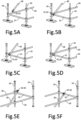
- FIGS 5A-5F show schematically successive stages of the fastening of the intermediate element 30 to the two ledgers 21, 22.
- Intermediate element 30 is firstly placed with the first distal outer end, which is provided with the two hook members 31, 32 with opposite orientation, at first ledger 21, see figure 5A .
- Intermediate element 30 is placed with both hook members 31, 32 over ledger 21, wherein ledger 21 is received between the two hook members, see figure 5B .
- Hook members 31, 32 now lie with their jaw parallel to an axis of ledger 21 and are not yet connected. The distance w here allows ledger 21 to be received between the two hook members 31, 32.
- intermediate element 30 At an opposite outer end the intermediate element is placed with the hooks 33, 34 provided there over the second ledger, see figures 5E and 5F , and latch 35 is knocked into place.
- Intermediate element 30 now lies immovably between the two ledgers 21, 22, and provides thereby additional load-bearing capacity and structural cohesion in the scaffolding. It is only at the position of the second scaffold element 22 that the scaffolder had to be present in order to knock latch 35 into place there.
- the invention thereby provides a particularly practical intermediate element 30 which can be advantageously applied in scaffolding of diverse nature and size.
- first distal outer end of the intermediate element is thus provided with a set of hook members with opposite orientation, but a similar set can also be provided at the opposite, second distal outer end.
- a tube clamp can also be provided at the second distal outer end for the purpose of a connection to the second ledger or the second scaffold element. And besides being possible between ledgers, a similar connection is also possible between opposite uprights.
Landscapes
- Engineering & Computer Science (AREA)
- Architecture (AREA)
- Mechanical Engineering (AREA)
- Civil Engineering (AREA)
- Structural Engineering (AREA)
- Mutual Connection Of Rods And Tubes (AREA)
Claims (7)
- Gerüst, umfassend ein System von Gerüstelementen, umfassend Ständer (10) und Riegel (20-22), die sich dazwischen erstrecken und mit den Ständern (10) verbunden sind, und umfassend mindestens ein Zwischenelement (30), das ein erstes Gerüstelement (21) und ein zweites Gerüstelement (22) zumindest im Wesentlichen entlang einer wechselseitig zueinander senkrechten Linie miteinander verbindet, wobei das Zwischenelement (30) einen länglichen Körper umfasst, von dem sich an einem distalen äußeren Ende ein Satz von zumindest im Wesentlichen parallelen Hakenelementen (31, 32) erstreckt, von denen jedes eine zumindest im Wesentlichen becherartige Backe umfasst, die um das erste Gerüstelement (21), das damit verbunden ist, herum greift, und wobei die Hakenelemente (31, 32) eine entgegengesetzte Ausrichtung haben, so dass die Backen um das erste Gerüstelement (21) auf entgegengesetzten Seiten herum greifen und hier einen wechselseitigen Abstand beigehalten, der größer als ein Abstand zwischen den entgegengesetzten Seiten des ersten Gerüstelements (21) ist, wobei die Hakenelemente (31, 32) im Wesentlichen plattenartig sind und wobei das Zwischenelement (30) einen kanalartigen Körper umfasst, dadurch gekennzeichnet, dass die im Wesentlichen plattenartigen Hakenelemente (31, 32) an entgegengesetzten Flanken des Zwischenelements (30) angebracht sind.
- Gerüst nach Anspruch 1, dadurch gekennzeichnet, dass die Hakenelemente (32, 32) durch eine Drehung des Zwischenelements (30) um eine Achse desselben zwischen einer Position, in der sie das erste Gerüstelement (21) umgreifen, und einer Position, in der sie von dem ersten Gerüstelement (21) gelöst werden können, verstellbar sind.
- Gerüst nach Anspruch 1 oder 2, dadurch gekennzeichnet, dass das erste Gerüstelement (21) rohrförmig ist und die Hakenelemente (32, 32) zumindest im Wesentlichen identisch geformt sind und jeweils eine im Wesentlichen U-förmige Backe aufweisen.
- Gerüst nach Anspruch 1, 2 oder 3, dadurch gekennzeichnet, dass die Hakenelemente (32, 32) zumindest im wesentlichen formschlüssig um das erste Gerüstelement (21) herum liegen.
- Gerüst nach einem oder mehreren der vorhergehenden Ansprüche, dadurch gekennzeichnet, dass das Zwischenelement (30) an einem gegenüberliegenden, zweiten distalen äußeren Ende eine Gerüstkupplung aufweist und unter Zwischenschaltung derselben nicht-drehbar mit einem zweiten Gerüstelement gekoppelt ist.
- Gerüst nach Anspruch 5, dadurch gekennzeichnet, dass das zweite Gerüstelement rohrförmig ist und die Gerüstkupplung eine Rohrschelle umfasst, die das zweite Gerüstelement klemmend umgreift.
- Gerüst nach Anspruch 5, dadurch gekennzeichnet, dass die Gerüstkupplung einen Satz von zumindest im Wesentlichen parallelen Hakenelementen (32, 32) umfasst, die sich vom zweiten äußeren Ende des Zwischenelements (30) aus erstrecken und jeweils mit einer zumindest im Wesentlichen becherartigen Backe um das damit verbundene zweite Gerüstelement herum in Eingriff stehen, wobei die Hakenelemente (32, 32) zumindest im Wesentlichen dieselbe Ausrichtung haben, so dass die Backen um das zweite Gerüstelement herum von derselben Seite aus in Eingriff stehen, wobei ein Riegel vorgesehen ist, der das zweite Gerüstelement von einer gegenüberliegenden Seite aus nicht drehbar verriegelt.
Applications Claiming Priority (2)
| Application Number | Priority Date | Filing Date | Title |
|---|---|---|---|
| NL1043444A NL1043444B1 (nl) | 2019-10-31 | 2019-10-31 | Steigerwerk en schoorelement daarvoor |
| PCT/IB2020/060052 WO2021084412A1 (en) | 2019-10-31 | 2020-10-27 | Scaffolding and intermediate element therefor |
Publications (3)
| Publication Number | Publication Date |
|---|---|
| EP4051850A1 EP4051850A1 (de) | 2022-09-07 |
| EP4051850B1 true EP4051850B1 (de) | 2024-10-09 |
| EP4051850C0 EP4051850C0 (de) | 2024-10-09 |
Family
ID=73740433
Family Applications (1)
| Application Number | Title | Priority Date | Filing Date |
|---|---|---|---|
| EP20820520.3A Active EP4051850B1 (de) | 2019-10-31 | 2020-10-27 | Gerüst und zwischenelement dafür |
Country Status (3)
| Country | Link |
|---|---|
| EP (1) | EP4051850B1 (de) |
| NL (1) | NL1043444B1 (de) |
| WO (1) | WO2021084412A1 (de) |
Families Citing this family (2)
| Publication number | Priority date | Publication date | Assignee | Title |
|---|---|---|---|---|
| CH717986A1 (de) * | 2020-10-22 | 2022-04-29 | Vitra Ag | Kreuzverband und Möbelbausatz. |
| EP4575138A1 (de) * | 2023-12-22 | 2025-06-25 | DOKA GmbH | Stiel, schalungsstütze, traggerüstteilkombination, traggerüstrahmen und verfahren zum aufbau eines traggerüstrahmens |
Citations (1)
| Publication number | Priority date | Publication date | Assignee | Title |
|---|---|---|---|---|
| FR1587165A (de) * | 1968-10-21 | 1970-03-13 |
Family Cites Families (3)
| Publication number | Priority date | Publication date | Assignee | Title |
|---|---|---|---|---|
| DE7128051U (de) * | 1971-07-22 | 1971-12-09 | Lawil Ag | Aussteifungselement fuer metallgerueste |
| DE20005629U1 (de) * | 2000-03-25 | 2000-06-29 | Krause-Werk GmbH & Co KG, 36304 Alsfeld | Strebe |
| KR101011595B1 (ko) * | 2010-09-14 | 2011-01-27 | 주식회사 한발 | 불균일 바닥면상 이동과 조립중 운용되는 짐수레와 단독조립형 발판을 구비한 블록 비계와 블록비계의 조립방법 |
-
2019
- 2019-10-31 NL NL1043444A patent/NL1043444B1/nl active
-
2020
- 2020-10-27 WO PCT/IB2020/060052 patent/WO2021084412A1/en not_active Ceased
- 2020-10-27 EP EP20820520.3A patent/EP4051850B1/de active Active
Patent Citations (1)
| Publication number | Priority date | Publication date | Assignee | Title |
|---|---|---|---|---|
| FR1587165A (de) * | 1968-10-21 | 1970-03-13 |
Also Published As
| Publication number | Publication date |
|---|---|
| EP4051850A1 (de) | 2022-09-07 |
| NL1043444B1 (nl) | 2021-07-19 |
| WO2021084412A1 (en) | 2021-05-06 |
| EP4051850C0 (de) | 2024-10-09 |
Similar Documents
| Publication | Publication Date | Title |
|---|---|---|
| AU2011209619B2 (en) | Scaffold system and method | |
| US6151851A (en) | Stackable support column system and method for multistory building construction | |
| US9861190B2 (en) | Wood gang form and method for constructing concrete building using same | |
| EP2880228B1 (de) | Gerüststruktur | |
| EP4051850B1 (de) | Gerüst und zwischenelement dafür | |
| US20120228060A1 (en) | High capacity vertical member for use with modular scaffolding | |
| MX2013008244A (es) | Aparato, metodo y sistema de andamio. | |
| US20170114555A1 (en) | Scaffolding section | |
| US3323271A (en) | Framework systems | |
| GB2534092A (en) | Scaffold clamps | |
| WO2011005087A1 (en) | Forkhead for use in a modular scaffolding system, and method of constructing a scaffold frame using the same | |
| EP1524386A1 (de) | Halterung für Seitenschutzelemente | |
| CN111219046B (zh) | 一种复合型脚手架搭设结构及其施工工艺 | |
| WO2017011860A1 (en) | Method of lifting panel with inserts | |
| CN211598005U (zh) | 一种工程施工用防护栏 | |
| GB2571432A (en) | Safety barrier apparatus and method of use thereof | |
| CN1022430C (zh) | 组合型钢管脚手架 | |
| AU2008100567A4 (en) | A scaffolding stand for use in a formwork support system | |
| CN214785944U (zh) | 便捷式高强度支模结构 | |
| WO2018140477A1 (en) | Scaffolding system for use with curvilinear walls and method of use | |
| CN2573611Y (zh) | 组合型落地式钢管脚手架 | |
| US20150144427A1 (en) | Scaffold extension systems and methods | |
| AU2013100389A4 (en) | Scaffolding system | |
| AU2013100304A4 (en) | Method and system for oblique scaffold connection | |
| CN121897139A (zh) | 一种室内预埋连墙件施工结构及方法 |
Legal Events
| Date | Code | Title | Description |
|---|---|---|---|
| STAA | Information on the status of an ep patent application or granted ep patent |
Free format text: STATUS: UNKNOWN |
|
| STAA | Information on the status of an ep patent application or granted ep patent |
Free format text: STATUS: THE INTERNATIONAL PUBLICATION HAS BEEN MADE |
|
| PUAI | Public reference made under article 153(3) epc to a published international application that has entered the european phase |
Free format text: ORIGINAL CODE: 0009012 |
|
| STAA | Information on the status of an ep patent application or granted ep patent |
Free format text: STATUS: REQUEST FOR EXAMINATION WAS MADE |
|
| 17P | Request for examination filed |
Effective date: 20220531 |
|
| AK | Designated contracting states |
Kind code of ref document: A1 Designated state(s): AL AT BE BG CH CY CZ DE DK EE ES FI FR GB GR HR HU IE IS IT LI LT LU LV MC MK MT NL NO PL PT RO RS SE SI SK SM TR |
|
| DAV | Request for validation of the european patent (deleted) | ||
| DAX | Request for extension of the european patent (deleted) | ||
| P01 | Opt-out of the competence of the unified patent court (upc) registered |
Effective date: 20230602 |
|
| GRAP | Despatch of communication of intention to grant a patent |
Free format text: ORIGINAL CODE: EPIDOSNIGR1 |
|
| STAA | Information on the status of an ep patent application or granted ep patent |
Free format text: STATUS: GRANT OF PATENT IS INTENDED |
|
| INTG | Intention to grant announced |
Effective date: 20240216 |
|
| GRAJ | Information related to disapproval of communication of intention to grant by the applicant or resumption of examination proceedings by the epo deleted |
Free format text: ORIGINAL CODE: EPIDOSDIGR1 |
|
| STAA | Information on the status of an ep patent application or granted ep patent |
Free format text: STATUS: REQUEST FOR EXAMINATION WAS MADE |
|
| INTC | Intention to grant announced (deleted) | ||
| GRAP | Despatch of communication of intention to grant a patent |
Free format text: ORIGINAL CODE: EPIDOSNIGR1 |
|
| STAA | Information on the status of an ep patent application or granted ep patent |
Free format text: STATUS: GRANT OF PATENT IS INTENDED |
|
| INTG | Intention to grant announced |
Effective date: 20240603 |
|
| GRAS | Grant fee paid |
Free format text: ORIGINAL CODE: EPIDOSNIGR3 |
|
| GRAA | (expected) grant |
Free format text: ORIGINAL CODE: 0009210 |
|
| STAA | Information on the status of an ep patent application or granted ep patent |
Free format text: STATUS: THE PATENT HAS BEEN GRANTED |
|
| AK | Designated contracting states |
Kind code of ref document: B1 Designated state(s): AL AT BE BG CH CY CZ DE DK EE ES FI FR GB GR HR HU IE IS IT LI LT LU LV MC MK MT NL NO PL PT RO RS SE SI SK SM TR |
|
| REG | Reference to a national code |
Ref country code: CH Ref legal event code: EP |
|
| REG | Reference to a national code |
Ref country code: DE Ref legal event code: R096 Ref document number: 602020039230 Country of ref document: DE |
|
| REG | Reference to a national code |
Ref country code: IE Ref legal event code: FG4D |
|
| U01 | Request for unitary effect filed |
Effective date: 20241030 |
|
| U07 | Unitary effect registered |
Designated state(s): AT BE BG DE DK EE FI FR IT LT LU LV MT NL PT RO SE SI Effective date: 20241111 |
|
| U20 | Renewal fee for the european patent with unitary effect paid |
Year of fee payment: 5 Effective date: 20241118 |
|
| PG25 | Lapsed in a contracting state [announced via postgrant information from national office to epo] |
Ref country code: IS Free format text: LAPSE BECAUSE OF FAILURE TO SUBMIT A TRANSLATION OF THE DESCRIPTION OR TO PAY THE FEE WITHIN THE PRESCRIBED TIME-LIMIT Effective date: 20250209 Ref country code: HR Free format text: LAPSE BECAUSE OF FAILURE TO SUBMIT A TRANSLATION OF THE DESCRIPTION OR TO PAY THE FEE WITHIN THE PRESCRIBED TIME-LIMIT Effective date: 20241009 |
|
| PG25 | Lapsed in a contracting state [announced via postgrant information from national office to epo] |
Ref country code: ES Free format text: LAPSE BECAUSE OF FAILURE TO SUBMIT A TRANSLATION OF THE DESCRIPTION OR TO PAY THE FEE WITHIN THE PRESCRIBED TIME-LIMIT Effective date: 20241009 |
|
| PG25 | Lapsed in a contracting state [announced via postgrant information from national office to epo] |
Ref country code: NO Free format text: LAPSE BECAUSE OF FAILURE TO SUBMIT A TRANSLATION OF THE DESCRIPTION OR TO PAY THE FEE WITHIN THE PRESCRIBED TIME-LIMIT Effective date: 20250109 |
|
| PG25 | Lapsed in a contracting state [announced via postgrant information from national office to epo] |
Ref country code: GR Free format text: LAPSE BECAUSE OF FAILURE TO SUBMIT A TRANSLATION OF THE DESCRIPTION OR TO PAY THE FEE WITHIN THE PRESCRIBED TIME-LIMIT Effective date: 20250110 |
|
| PG25 | Lapsed in a contracting state [announced via postgrant information from national office to epo] |
Ref country code: PL Free format text: LAPSE BECAUSE OF FAILURE TO SUBMIT A TRANSLATION OF THE DESCRIPTION OR TO PAY THE FEE WITHIN THE PRESCRIBED TIME-LIMIT Effective date: 20241009 |
|
| PG25 | Lapsed in a contracting state [announced via postgrant information from national office to epo] |
Ref country code: RS Free format text: LAPSE BECAUSE OF FAILURE TO SUBMIT A TRANSLATION OF THE DESCRIPTION OR TO PAY THE FEE WITHIN THE PRESCRIBED TIME-LIMIT Effective date: 20250109 |
|
| REG | Reference to a national code |
Ref country code: CH Ref legal event code: PL |
|
| PG25 | Lapsed in a contracting state [announced via postgrant information from national office to epo] |
Ref country code: SM Free format text: LAPSE BECAUSE OF FAILURE TO SUBMIT A TRANSLATION OF THE DESCRIPTION OR TO PAY THE FEE WITHIN THE PRESCRIBED TIME-LIMIT Effective date: 20241009 |
|
| PG25 | Lapsed in a contracting state [announced via postgrant information from national office to epo] |
Ref country code: MC Free format text: LAPSE BECAUSE OF FAILURE TO SUBMIT A TRANSLATION OF THE DESCRIPTION OR TO PAY THE FEE WITHIN THE PRESCRIBED TIME-LIMIT Effective date: 20241009 |
|
| PG25 | Lapsed in a contracting state [announced via postgrant information from national office to epo] |
Ref country code: CH Free format text: LAPSE BECAUSE OF NON-PAYMENT OF DUE FEES Effective date: 20241031 |
|
| PG25 | Lapsed in a contracting state [announced via postgrant information from national office to epo] |
Ref country code: SK Free format text: LAPSE BECAUSE OF FAILURE TO SUBMIT A TRANSLATION OF THE DESCRIPTION OR TO PAY THE FEE WITHIN THE PRESCRIBED TIME-LIMIT Effective date: 20241009 |
|
| PG25 | Lapsed in a contracting state [announced via postgrant information from national office to epo] |
Ref country code: CZ Free format text: LAPSE BECAUSE OF FAILURE TO SUBMIT A TRANSLATION OF THE DESCRIPTION OR TO PAY THE FEE WITHIN THE PRESCRIBED TIME-LIMIT Effective date: 20241009 |
|
| PLBE | No opposition filed within time limit |
Free format text: ORIGINAL CODE: 0009261 |
|
| STAA | Information on the status of an ep patent application or granted ep patent |
Free format text: STATUS: NO OPPOSITION FILED WITHIN TIME LIMIT |
|
| 26N | No opposition filed |
Effective date: 20250710 |
|
| PG25 | Lapsed in a contracting state [announced via postgrant information from national office to epo] |
Ref country code: IE Free format text: LAPSE BECAUSE OF NON-PAYMENT OF DUE FEES Effective date: 20241027 |
|
| U20 | Renewal fee for the european patent with unitary effect paid |
Year of fee payment: 6 Effective date: 20251014 |
|
| PGFP | Annual fee paid to national office [announced via postgrant information from national office to epo] |
Ref country code: GB Payment date: 20251016 Year of fee payment: 6 |
|
| PG25 | Lapsed in a contracting state [announced via postgrant information from national office to epo] |
Ref country code: CY Free format text: LAPSE BECAUSE OF FAILURE TO SUBMIT A TRANSLATION OF THE DESCRIPTION OR TO PAY THE FEE WITHIN THE PRESCRIBED TIME-LIMIT; INVALID AB INITIO Effective date: 20201027 |
|
| PG25 | Lapsed in a contracting state [announced via postgrant information from national office to epo] |
Ref country code: HU Free format text: LAPSE BECAUSE OF FAILURE TO SUBMIT A TRANSLATION OF THE DESCRIPTION OR TO PAY THE FEE WITHIN THE PRESCRIBED TIME-LIMIT; INVALID AB INITIO Effective date: 20201027 |