EP4051837B1 - Tufting tool module - Google Patents
Tufting tool module Download PDFInfo
- Publication number
- EP4051837B1 EP4051837B1 EP20797889.1A EP20797889A EP4051837B1 EP 4051837 B1 EP4051837 B1 EP 4051837B1 EP 20797889 A EP20797889 A EP 20797889A EP 4051837 B1 EP4051837 B1 EP 4051837B1
- Authority
- EP
- European Patent Office
- Prior art keywords
- tufting
- tools
- cut outs
- base block
- tool
- Prior art date
- Legal status (The legal status is an assumption and is not a legal conclusion. Google has not performed a legal analysis and makes no representation as to the accuracy of the status listed.)
- Active
Links
Images




Classifications
-
- D—TEXTILES; PAPER
- D05—SEWING; EMBROIDERING; TUFTING
- D05C—EMBROIDERING; TUFTING
- D05C15/00—Making pile fabrics or articles having similar surface features by inserting loops into a base material
- D05C15/04—Tufting
- D05C15/08—Tufting machines
- D05C15/16—Arrangements or devices for manipulating threads
- D05C15/22—Loop-catching arrangements, e.g. loopers; Driving mechanisms therefor
Definitions
- the present disclosure relates to tufting, and in particular to a module for tufting tools.
- a textile is produced by a textile process in which a thread is inserted on a primary base.
- Specialized machinery can be used to produce a tufted textile.
- Such machinery typically can make use of tufting tools to insert the thread to the primary base and to apply the thread in a described manner.
- the tufting tools are provided in a tufting tool module to facilitate reconfiguration of the machinery for different applications.
- a tufting tool module a plurality of tools are embedded within a common cast body member in a side-by-side configuration. To ensure a good function of the loop forming and a good quality of the tufted fabric, it is essential that the different tufting tools are aligned with each other with very high precision.
- a tufting machine can hold 2000 needles, hooks and knifes, and they typically match each other with a precision of tenths of a millimeter, or sometimes even hundreds of a millimeter.
- tufting tool modules are described in for example US 4303024 and US 5860373 .
- a tufting tool module is described having a hole in the securing portion of hooks in order to receive metal for securing the hooks in the base member of the tufting tool module.
- US 4, 241,675 and US 4,739,717 describe similar known tufting tool modules.
- the plurality of tufting tools cast to the base of the tufting tool module tends to be laterally displaced in relation to each other.
- the result is that the tufting tool module in some cases does not meet the requirements with regard to tolerances. Subsequent re-alignment of the tufting tools can then become necessary which is undesired and increases production costs and production time.
- a tufting tool module for a tufting machine.
- the tufting tool module comprises a plurality of tufting tools.
- the tufting tools have a head portion and a securing portion.
- the securing portion of each tufting tool is casted in a base block.
- the securing portions of each tufting tool are provided with at least two cut outs located inside the base block.
- the tufting tools are formed such that an upper side of the head portion is displaced in relation to an upper side of the securing portion.
- At least one of said at least two cut outs have a cross-section in the range of 1 - 5 mm, typically, in the range of 1.5 - 2.5 mm.
- at least one of the at least two cut outs have a cross-section of 2 mm.
- wo through holes are formed in the securing portion located inside the base block. Some or all of the cut outs can be circular to provide better performance with regard to reducing the dislocation of the tufting tools during the casting process.
- tufting tools including, but not limited to tufting tool modules having a base block made of zinc.
- the tufting tools can be any tufting tool casted in a base block including but not limited to, hooks, loopers, reeds, knives, and Level Cut Looper (LCL) tools.
- LCL Level Cut Looper
- FIG. 1 an exemplary tufting tool module 10 in accordance with a first embodiment is depicted in a bottom view.
- the tufting tool module 10 comprises a plurality of tufting tools 20 cast in a base block 12.
- the tufting tool 20 is in the embodiment of Fig. 1 a hook tool but can in accordance with other embodiments be other types of tufting tools as will be exemplified in conjunction with the description of other embodiments.
- the base block 12 can typically be a zinc block in which a securing portion of the tufting tools 20 is cast.
- the base blocks When in use in a tufting machine, the base blocks are typically fixed side by side to a bar on the tufting machine. It is essential that the tufting tools in the base block are fixed so that they have exactly the right position in relation to each other and to the other types of tufting tools. For example, the needles must meet with its hook and the knife must meet its hook with a very high precision.
- the base block have locator pins that corresponds to holes in the bar of the tufting machine and in other cases the base blocks are assembled side by side. It is therefore a requirement that the precision between the crucial parts of the tufting tools and the locator pins or base block sides is very high. It has been discovered that the tufting tools tend to be dislocated during the casting process. The dislocation comes from the flow of the molted zinc inserted to the mold and also from uncontrolled shrinkage when the metal, for example zinc, is cooling down.
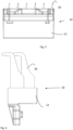
- the tufting tool module 10 in accordance with the first embodiment is depicted in a side view.
- the hooks 20 can be provided with an insert.
- the insert is typically formed by a material being harder than the rest of the tufting tool 20.
- the insert can typically be provided to protect the hooks 20 from wear from e.g. a knife co-operating with the hooks during operation of a tufting machine in which the tufting tool module 10 can be mounted.
- a beveling 16 to ensure a clearance for a cutting knife is shown in Fig. 2 .
- the tufting tool module 10 in accordance with the first embodiment is depicted in a cross-sectional side view.
- the hooks 20 are formed by a securing portion 24 configured to mount the hooks to the base block 12 and a head portion 22 protruding from the securing portion 24.
- the head portion 22 is provided with an upper edge 23.
- the securing portion 24 also has an upper edge 25.
- the upper edge 25 of the securing portion 24 can in accordance with some embodiments be displaced in relation to the upper edge 23 of the head portion 22. In particular the upper edge 25 of the securing portion 24 can be lower in relation to the upper edge 23 of the head portion 22.
- the securing portion 24 is provided with cut outs 26, 28.
- the cut outs 26, 28 are two, circular, through holes
- the cut outs 26, 28 are provided to reduce or eliminate dislocation of the tufting tools 20 during casting of the base block 12 of the tufting tool module 10.
- the casting procedure itself can result in that pressure is applied to the securing portion 24 of the tufting tools 20 whereby when the casting procedure is ended the tufting tools 20 can become displaced in relation to the position in which the tufting tools where aligned before the casting.
- the provision of the cut outs 26, 28 can reduce the lateral pressure differences between the different tufting tools 20 of the tufting tool module 10. This is because the cast material, such as zinc, is allowed to move more freely within the cast during casting of the base block 12.
- the cut outs will during the cooling phase of the metal, e.g. zinc, control and stabilize the shrinkage so the tufting tools will not be dislocated. In other words, dislocation during the casting process can hereby be reduced or eliminated.
- tufting tool 20, a hook, in accordance with the first embodiment is depicted in a side view.
- the hook 20 is shown with cut outs 26, 28 in the securing portion 24 as described in conjunction with Fig. 3 .
- the cut outs 26, 28 are formed as circular holes located at some distance from each other.
- the cross section of the cut outs 26, 28 can advantageously be in the range of 1 - 5 mm. It is preferred to use a cross-section of 1.5 mm - 2.5mm and 2mm is used in the embodiment of Fig. 4 to maximize the benefit of the cut outs 26, 28.
- the cut outs can advantageously be provided simultaneously with forming the tufting tool 20.
- the cut outs 26, 28 are formed by electrical discharge machining.
- FIG. 5 an exemplary tufting tool module 10 in accordance with a second embodiment is depicted in a rear view.
- the tufting tool module 10 comprises a plurality of tufting tools 30 cast in a base block 12.
- the tufting tool 30 is in the embodiment of Fig. 5 a looper.
- the base block 12 can typically be a zinc block in which a securing portion of the loopers 30 are cast.
- the tufting tool module 10 in accordance with the second embodiment is depicted in a side view.
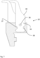
- the tufting tool module 10 in accordance with the second embodiment is depicted in a cross-sectional side view.
- the loopers 30 comprise a securing portion 34 configured to mount the loopers 30 to the base block 12.
- the securing portion 34 is provided with cut outs 36, 37, 38, which are not according to the invention.
- the cut outs 36, 37, 38 comprise in the embodiment of Fig. 7 one, circular, through hole and two semi-circular cut outs at the rim of the securing portion.
- the cut outs 36, 37, and 38 can be formed in other configurations as well.
- the cut outs 36, 37 and 38 are provided to reduce or eliminate dislocation of the tufting tools 30 during casting of the base block 12 of the tufting tool module 10.
- the casting procedure itself can result in that pressure is applied to the securing portion 34 of the tufting tools 30 whereby when the casting procedure is ended the tufting tools 30 can become displaced in relation to the position in which the tufting tools were aligned before the casting.
- the provision of the cut outs 36, 37, and 38 can reduce the lateral pressure differences between the different tufting tools 30 of the tufting tool module 10. This is because the cast material, such as zinc, is allowed to move more freely within the cast during casting of the base block 12.
- the cut outs 36, 37, and 38 will during the cooling phase of the metal, e.g. zinc, control and stabilize the shrinkage so the tufting tools will not be dislocated. In other words, dislocation during the casting process can hereby be reduced or eliminated.
- Fig. 8 the tufting tool 30, a looper, in accordance with the second embodiment is depicted in a side view.
- the looper 30 is shown with cut outs 36, 37 and 38, not according to the invention, in the securing portion 34 as described in conjunction with Fig. 7 .
- At least two cut outs 36, 37 and 38 are formed as circular holes while others can be formed as semi-circular holes, the holes being respectively located at some distance from each other.
- the cross section of the cut outs 36, 37 and 38 can advantageously be in the range of 1 - 5 mm. It is preferred to use a cross-section of 1.5 mm - 2.5mm and 2mm in the embodiment of Fig. 8 to maximize the benefit of the cut outs 36, 37 and 38.
- the cut outs 36, 37, and 38 can, as for the first embodiment, advantageously be provided simultaneously with forming the tufting tool 30.
- the cut outs 36, 37 and 38 are formed by electrical discharge machining.
- FIG. 9 an exemplary tufting tool module 10 in accordance with a third embodiment is depicted in a bottom view.
- the tufting tool module 10 comprises a plurality of tufting tools 40 cast in a base block 12.
- the tufting tool 40 is in the embodiment of Fig. 9 a Level Cut Looper tool (LCL).
- the LCL 40 comprises a moving part called slider 41, see Fig. 10 , running at the back side of the tufting tool 40 casted in the base block 12.
- the moving part 41 decides if a loop shall be cut or not. This moving part 41 is placed in the center of the LCL tool 40, preventing the possibility to make a cut out in the center.
- the base block 12 can typically be a zinc block in which a securing portion of the LCLs 40 is cast.
- the tufting tool module 10 in accordance with the third embodiment is depicted in a side view.
- the tufting tool module 10 in accordance with the third embodiment is depicted in a cross-sectional side view.
- the LCLs 40 comprises a securing portion 44 configured to mount the LCLs 40 to the base block 12.
- the securing portion 44 is provided with cut outs 45, 46, 47, 48, and 49.
- the cut outs 45, 46, 47, 48, and 49 comprise in the embodiment of Fig. 11 one, circular, through hole 45 , a forward rectangular cut out 46, two rear rectangular cut outs 48,49 at the rim of the securing portion, and a triangular cut out 47.
Landscapes
- Engineering & Computer Science (AREA)
- Chemical & Material Sciences (AREA)
- Materials Engineering (AREA)
- Textile Engineering (AREA)
- Molds, Cores, And Manufacturing Methods Thereof (AREA)
Description
- The present disclosure relates to tufting, and in particular to a module for tufting tools.
- In tufting, a textile is produced by a textile process in which a thread is inserted on a primary base. Specialized machinery can be used to produce a tufted textile. Such machinery typically can make use of tufting tools to insert the thread to the primary base and to apply the thread in a described manner. In some applications, the tufting tools are provided in a tufting tool module to facilitate reconfiguration of the machinery for different applications. In a tufting tool module, a plurality of tools are embedded within a common cast body member in a side-by-side configuration. To ensure a good function of the loop forming and a good quality of the tufted fabric, it is essential that the different tufting tools are aligned with each other with very high precision. Typically, a tufting machine can hold 2000 needles, hooks and knifes, and they typically match each other with a precision of tenths of a millimeter, or sometimes even hundreds of a millimeter.
- Known tufting tool modules are described in for example
US 4303024 andUS 5860373 . For example, inUS 4303024 a tufting tool module is described having a hole in the securing portion of hooks in order to receive metal for securing the hooks in the base member of the tufting tool module. Also,US 4, 241,675 andUS 4,739,717 describe similar known tufting tool modules. - There is a constant desire to improve textile machines including tufting machines and parts used within such machinery. Hence, there is a need for an improved tufting tool module that can be used in a tufting machine.
- It is an object of the present invention to improve tufting machines and in particular to provide an improved tufting tool module.
- This object and/or others are obtained by the tufting tool module as set out in the appended claims.
- As has been realized, during the casting process of a tufting tool module, the plurality of tufting tools cast to the base of the tufting tool module tends to be laterally displaced in relation to each other. The result is that the tufting tool module in some cases does not meet the requirements with regard to tolerances. Subsequent re-alignment of the tufting tools can then become necessary which is undesired and increases production costs and production time.
- This problem is solved by a tufting tool module as set out in the appended claims.
- In accordance with the invention a tufting tool module for a tufting machine is provided. The tufting tool module comprises a plurality of tufting tools. The tufting tools have a head portion and a securing portion. The securing portion of each tufting tool is casted in a base block. The securing portions of each tufting tool are provided with at least two cut outs located inside the base block. By providing such cut outs it is possible to reduce the lateral pressure differences between the different tufting tools of the tufting tool module during casting of the base block. This is because the cast material, such as zinc, is allowed to move more freely within the cast during casting of the base block. Furthermore, the cut outs will during the cooling phase of the metal, e.g. zinc, control and stabilize the shrinkage so the tufting tools will not be dislocated. In other words, dislocation of the tufting tools during the casting process can hereby be reduced or eliminated. The result is a tufting tool module with improved tolerances.
- In accordance with some embodiments, the tufting tools are formed such that an upper side of the head portion is displaced in relation to an upper side of the securing portion.
- In accordance with some embodiments, at least one of said at least two cut outs have a cross-section in the range of 1 - 5 mm, typically, in the range of 1.5 - 2.5 mm. In particular at least one of the at least two cut outs have a cross-section of 2 mm. Hereby dislocation can be minimized.
- In accordance with the invention, wo through holes are formed in the securing portion located inside the base block. Some or all of the cut outs can be circular to provide better performance with regard to reducing the dislocation of the tufting tools during the casting process.
- The provision of cut outs in tufting tools is beneficial for all types of tufting tools modules including, but not limited to tufting tool modules having a base block made of zinc. The tufting tools can be any tufting tool casted in a base block including but not limited to, hooks, loopers, reeds, knives, and Level Cut Looper (LCL) tools.
- The present invention will now be described in more detail by way of non-limiting examples and with reference to the accompanying drawings, in which:
-
Figs. 1 - 3 are views illustrating a tufting tool module in accordance with a first embodiment, -
Fig. 4 is a view of a tufting tool for use in the tufting tool module in accordance with the first embodiment, - -
Figs. 5 - 7 are views illustrating a tufting tool module in accordance with a second embodiment, with cut-outs that are not according to the invention, -
Fig. 8 is a view of a tufting tool for use in the tufting tool module in accordance with the second embodiment, -
Figs. 9 - 11 are views illustrating a tufting tool module in accordance with a first embodiment, with cut-outs that are not in accordance with the invention, and -
Fig. 12 is a view of a tufting tool for use in the tufting tool module in accordance with the first embodiment, with cut-outs that are not in accordance with the invention. - In the following, exemplary tufting tool modules will be described. In the Figures, the same reference numerals designate identical or corresponding elements throughout the several figures. It will be appreciated that these figures are for illustration only and are not in any way restricting the scope of the invention. Also, it is possible to combine features from different described embodiments to meet specific implementation needs.
- In
Fig. 1 , an exemplarytufting tool module 10 in accordance with a first embodiment is depicted in a bottom view. Thetufting tool module 10 comprises a plurality oftufting tools 20 cast in abase block 12. Thetufting tool 20 is in the embodiment ofFig. 1 a hook tool but can in accordance with other embodiments be other types of tufting tools as will be exemplified in conjunction with the description of other embodiments. Thebase block 12 can typically be a zinc block in which a securing portion of thetufting tools 20 is cast. - When in use in a tufting machine, the base blocks are typically fixed side by side to a bar on the tufting machine. It is essential that the tufting tools in the base block are fixed so that they have exactly the right position in relation to each other and to the other types of tufting tools. For example, the needles must meet with its hook and the knife must meet its hook with a very high precision. In some cases, the base block have locator pins that corresponds to holes in the bar of the tufting machine and in other cases the base blocks are assembled side by side. It is therefore a requirement that the precision between the crucial parts of the tufting tools and the locator pins or base block sides is very high. It has been discovered that the tufting tools tend to be dislocated during the casting process. The dislocation comes from the flow of the molted zinc inserted to the mold and also from uncontrolled shrinkage when the metal, for example zinc, is cooling down.
- In
Fig. 2 , thetufting tool module 10 in accordance with the first embodiment is depicted in a side view. Thehooks 20 can be provided with an insert. The insert is typically formed by a material being harder than the rest of thetufting tool 20. The insert can typically be provided to protect thehooks 20 from wear from e.g. a knife co-operating with the hooks during operation of a tufting machine in which thetufting tool module 10 can be mounted. Abeveling 16 to ensure a clearance for a cutting knife is shown inFig. 2 . - In
Fig. 3 , thetufting tool module 10 in accordance with the first embodiment is depicted in a cross-sectional side view. Thehooks 20 are formed by a securingportion 24 configured to mount the hooks to thebase block 12 and ahead portion 22 protruding from the securingportion 24. Thehead portion 22 is provided with anupper edge 23. The securingportion 24 also has anupper edge 25. Theupper edge 25 of the securingportion 24 can in accordance with some embodiments be displaced in relation to theupper edge 23 of thehead portion 22. In particular theupper edge 25 of the securingportion 24 can be lower in relation to theupper edge 23 of thehead portion 22. Further, the securingportion 24 is provided withcut outs cut outs - It can be advantageous to locate one through hole at a location corresponding to the forward rim of the
base block 12, i.e. the rim facing thehead portion 22. This would be throughhole 28 in the embodiment shown inFig. 3 . Also, it can be advantageous to locate the through holes at a location where the distance is equal to or close to equal to the upper and lower edge, respectively, of the securingportion 24. - The
cut outs tufting tools 20 during casting of thebase block 12 of thetufting tool module 10. Thus, when thebase block 12 is cast in zinc, or some other material, the casting procedure itself can result in that pressure is applied to the securingportion 24 of thetufting tools 20 whereby when the casting procedure is ended thetufting tools 20 can become displaced in relation to the position in which the tufting tools where aligned before the casting. The provision of thecut outs different tufting tools 20 of thetufting tool module 10. This is because the cast material, such as zinc, is allowed to move more freely within the cast during casting of thebase block 12. Furthermore, the cut outs will during the cooling phase of the metal, e.g. zinc, control and stabilize the shrinkage so the tufting tools will not be dislocated. In other words, dislocation during the casting process can hereby be reduced or eliminated. - In
Fig. 4 , thetufting tool 20, a hook, in accordance with the first embodiment is depicted in a side view. Thehook 20 is shown withcut outs portion 24 as described in conjunction withFig. 3 . Thecut outs cut outs Fig. 4 to maximize the benefit of thecut outs tufting tool 20. In accordance with some embodiments thecut outs - In
Fig. 5 , an exemplarytufting tool module 10 in accordance with a second embodiment is depicted in a rear view. Thetufting tool module 10 comprises a plurality oftufting tools 30 cast in abase block 12. Thetufting tool 30 is in the embodiment ofFig. 5 a looper. Thebase block 12 can typically be a zinc block in which a securing portion of theloopers 30 are cast. - In
Fig. 6 , thetufting tool module 10 in accordance with the second embodiment is depicted in a side view. InFig. 7 , thetufting tool module 10 in accordance with the second embodiment is depicted in a cross-sectional side view. Theloopers 30 comprise a securingportion 34 configured to mount theloopers 30 to thebase block 12. The securingportion 34 is provided withcut outs cut outs Fig. 7 one, circular, through hole and two semi-circular cut outs at the rim of the securing portion. However, thecut outs cut outs tufting tools 30 during casting of thebase block 12 of thetufting tool module 10. Thus, when thebase block 12 is cast in zinc, or some other material, the casting procedure itself can result in that pressure is applied to the securingportion 34 of thetufting tools 30 whereby when the casting procedure is ended thetufting tools 30 can become displaced in relation to the position in which the tufting tools were aligned before the casting. Thus, for the second embodiment, the provision of thecut outs different tufting tools 30 of thetufting tool module 10. This is because the cast material, such as zinc, is allowed to move more freely within the cast during casting of thebase block 12. Thecut outs - In
Fig. 8 , thetufting tool 30, a looper, in accordance with the second embodiment is depicted in a side view. Thelooper 30 is shown withcut outs portion 34 as described in conjunction withFig. 7 . At least twocut outs cut outs Fig. 8 to maximize the benefit of thecut outs cut outs tufting tool 30. In accordance with some embodiments thecut outs - In
Fig. 9 , an exemplarytufting tool module 10 in accordance with a third embodiment is depicted in a bottom view. Thetufting tool module 10 comprises a plurality oftufting tools 40 cast in abase block 12. Thetufting tool 40 is in the embodiment ofFig. 9 a Level Cut Looper tool (LCL). TheLCL 40 comprises a moving part calledslider 41, seeFig. 10 , running at the back side of thetufting tool 40 casted in thebase block 12. In anLCL tool 40 the movingpart 41 decides if a loop shall be cut or not. This movingpart 41 is placed in the center of theLCL tool 40, preventing the possibility to make a cut out in the center. Thebase block 12 can typically be a zinc block in which a securing portion of theLCLs 40 is cast. - In
Fig. 10 , thetufting tool module 10 in accordance with the third embodiment is depicted in a side view. InFig. 11 , thetufting tool module 10 in accordance with the third embodiment is depicted in a cross-sectional side view. TheLCLs 40 comprises a securingportion 44 configured to mount theLCLs 40 to thebase block 12. The securingportion 44 is provided withcut outs cut outs Fig. 11 one, circular, throughhole 45 , a forward rectangular cut out 46, two rearrectangular cut outs cut outs tufting tools 40 during casting of thebase block 12 of thetufting tool module 10. Thus, when thebase block 12 is cast in zinc, or some other material, the casting procedure itself can result in that pressure is applied to the securingportion 34 of thetufting tools 40 whereby when the casting procedure is ended thetufting tools 40 can become displaced in relation to the position in which the tufting tools where aligned before the casting. Thus, for the third embodiment, the provision of thecut outs different tufting tools 40 of thetufting tool module 10. This is because the cast material, such as zinc, is allowed to move more freely within the cast during casting of thebase block 12. Thecut outs - In
Fig. 12 , thetufting tool 40, an LCL, in accordance with the third embodiment is depicted in a side view. TheLCL 40 is shown withcut outs portion 44 as described in conjunction withFig. 11 . The cross section of thecut outs Fig. 12 to maximize the benefit of thecut outs cut outs tufting tool 40. In accordance with some embodiments thecut outs - The provision of cut outs in tufting tools is beneficial for all types of tufting tools modules including, but not limited to tufting tool modules having a base block made of zinc. The tufting tools can be any tufting tool casted in a base block including, but not limited to, hooks, loopers, reeds, knives, and Level Cut Looper (LCL) tools.
Claims (13)
- A tufting tool module (10) for a tufting machine, the tufting tool module (10) comprising a plurality of tufting tools (20, 30, 40), the tufting tools comprising a head portion (22, 32,42) and a securing portion (24,34,44), wherein the securing portion of each tufting tool is casted in a base block (12) characterized in that the securing portions of each tufting tool is provided with at least two cut outs (26,28, 36, 37, 38, 45, 46, 47, 48, 49) located inside the base block, said at least two cut outs comprising two through holes (26, 28) formed in the securing portion located inside the base block.
- The tufting tool module according to claim 1, wherein the tufting tools are formed such that an upper side (23) of the head portion (22) is displaced in relation to an upper side (25) of the securing portion (24).
- The tufting tool module according to any of claims 1 - 2, wherein at least one of said at least two cut outs have a cross-section in the range of 1 - 5 mm.
- The tufting tool module according to any of claims 1 - 3, wherein at least one of said at least two cut outs have a cross-section in the range of 1.5 - 2.5 mm.
- The tufting tool module according to any of claims 1 - 4, wherein at least one of said at least two cut outs have a cross-section of 2 mm.
- The module according to any of claims 1 - 5, wherein at least one of said at least two cut outs is circular.
- The module according to any of claims 1 - 6, wherein one through hole is located at the forward rim of the base block facing the head portion of the tufting tool.
- The module according to any of claims 1 - 7, wherein said base block is a casted zinc block.
- The module according to any of claims 1 - 8, wherein said tufting tools are hooks (20).
- The module according to any of claims 1 - 8, wherein said tufting tools are loopers (30).
- The module according to any of claims 1 - 8, wherein said tufting tools are reeds.
- The module according to any of claims 1 - 8, wherein said tufting tools are knives.
- The module according to any of claims 1 - 8, wherein said tufting tools are Level Cut Looper tools (40).
Applications Claiming Priority (2)
| Application Number | Priority Date | Filing Date | Title |
|---|---|---|---|
| SE1951234 | 2019-10-29 | ||
| PCT/SE2020/051015 WO2021086250A1 (en) | 2019-10-29 | 2020-10-21 | Tufting tool module |
Publications (2)
| Publication Number | Publication Date |
|---|---|
| EP4051837A1 EP4051837A1 (en) | 2022-09-07 |
| EP4051837B1 true EP4051837B1 (en) | 2025-04-02 |
Family
ID=73030189
Family Applications (1)
| Application Number | Title | Priority Date | Filing Date |
|---|---|---|---|
| EP20797889.1A Active EP4051837B1 (en) | 2019-10-29 | 2020-10-21 | Tufting tool module |
Country Status (5)
| Country | Link |
|---|---|
| US (1) | US11840787B2 (en) |
| EP (1) | EP4051837B1 (en) |
| JP (1) | JP2023501106A (en) |
| CN (1) | CN114729486B (en) |
| WO (1) | WO2021086250A1 (en) |
Families Citing this family (2)
| Publication number | Priority date | Publication date | Assignee | Title |
|---|---|---|---|---|
| USD1056680S1 (en) | 2021-02-16 | 2025-01-07 | Card-Monroe Corp. | Gauge module |
| US11585029B2 (en) | 2021-02-16 | 2023-02-21 | Card-Monroe Corp. | Tufting maching and method of tufting |
Family Cites Families (14)
| Publication number | Priority date | Publication date | Assignee | Title |
|---|---|---|---|---|
| GB889739A (en) * | 1959-04-16 | 1962-02-21 | Hobourn F N F Ltd | Improvements relating to flat warp knitting machines |
| US3485195A (en) * | 1967-05-09 | 1969-12-23 | Torrington Co | Tufting machine needle assembly |
| DE2946092A1 (en) * | 1978-11-16 | 1980-06-04 | Spencer Wright Ind Inc | Tufting machine gripper-yoke assembly - has carrier composed of two members each supporting a complementary array of grippers and yokes |
| US4241675A (en) * | 1979-02-22 | 1980-12-30 | Spencer Wright Industries, Inc. | Modular gauge parts assembly for cut/loop tufting machines |
| US4303024A (en) | 1980-04-26 | 1981-12-01 | Spencer Wright Industries, Inc. | Tufting machine hook module |
| US4313388A (en) * | 1980-06-06 | 1982-02-02 | Spencer Wright Industries, Inc. | Modular hook assembly for staggered needle cut pile tufting machines |
| GB8620016D0 (en) | 1986-08-16 | 1986-09-24 | Cobble Blackburn Ltd | Tufting machine gauge parts |
| EP0741811B1 (en) | 1994-02-28 | 1997-10-29 | Jos. Zimmermann GmbH & Co. KG | Tufting-tool module |
| US6672230B2 (en) * | 2002-01-03 | 2004-01-06 | Tuftco Corporation | Modular block assembly for tufting machine |
| CN2871574Y (en) * | 2006-01-11 | 2007-02-21 | 王益民 | Settling component of tricot machine |
| EP1826306B1 (en) * | 2006-02-24 | 2018-01-24 | Groz-Beckert KG | Looper device for a tufting machine |
| EP1908871B1 (en) * | 2006-10-06 | 2019-08-07 | Groz-Beckert KG | Looper for tufting machine |
| EP1953289A1 (en) * | 2007-02-01 | 2008-08-06 | Groz-Beckert KG | Hook for a tufting machine |
| CN203807750U (en) * | 2014-04-11 | 2014-09-03 | 乐清市塔夫特机械有限公司 | High-cutting low-looping tufting system of multicolor computerized jacquard tufting machine and tufting machine |
-
2020
- 2020-10-21 CN CN202080073239.5A patent/CN114729486B/en active Active
- 2020-10-21 US US17/772,292 patent/US11840787B2/en active Active
- 2020-10-21 EP EP20797889.1A patent/EP4051837B1/en active Active
- 2020-10-21 WO PCT/SE2020/051015 patent/WO2021086250A1/en not_active Ceased
- 2020-10-21 JP JP2022523202A patent/JP2023501106A/en active Pending
Also Published As
| Publication number | Publication date |
|---|---|
| JP2023501106A (en) | 2023-01-18 |
| US11840787B2 (en) | 2023-12-12 |
| CN114729486B (en) | 2023-06-30 |
| CN114729486A (en) | 2022-07-08 |
| US20220380954A1 (en) | 2022-12-01 |
| EP4051837A1 (en) | 2022-09-07 |
| WO2021086250A1 (en) | 2021-05-06 |
Similar Documents
| Publication | Publication Date | Title |
|---|---|---|
| US11840787B2 (en) | Tufting tool module | |
| US10661352B2 (en) | Parting lathe tool | |
| US4195580A (en) | Mounting block for tufting machine gauge parts | |
| US2846756A (en) | Cutoff tool and holder therefor | |
| US4241675A (en) | Modular gauge parts assembly for cut/loop tufting machines | |
| US2964833A (en) | Cutoff tool and holder therefor | |
| US10738400B2 (en) | Tool module for textile machines | |
| KR101243290B1 (en) | Movable die unit for die-casting | |
| EP4055221B1 (en) | Method of producing a tufting tool | |
| US9284671B2 (en) | Tool module for textile machine | |
| KR102266681B1 (en) | Mold assembly for forming and cutting insoles | |
| CN218203336U (en) | Split type dial structure of going up | |
| EP2454060B1 (en) | A blade-blade holder support group | |
| US2601108A (en) | Gang punching machine | |
| JP2021084138A (en) | Cutting tool | |
| KR101750164B1 (en) | blanking press metallic mold for manufacturing shim | |
| US4477957A (en) | Method to replace looper elements | |
| KR101556737B1 (en) | Cutting insert and cutting tool for mounting the same | |
| US3027623A (en) | Clamp-type holder for throw-away and indexible cutting inserts | |
| KR101575169B1 (en) | three corners cutting insert for relief machining | |
| CN114192656B (en) | Die for balancing punching side force | |
| KR200442225Y1 (en) | Material guide device of progressive mold | |
| JP2019516871A (en) | Textile processing module having a textile tool module and a textile tool module | |
| US2101002A (en) | Mounting for slicer blades | |
| US20010018854A1 (en) | Toolholder with a removable head |
Legal Events
| Date | Code | Title | Description |
|---|---|---|---|
| STAA | Information on the status of an ep patent application or granted ep patent |
Free format text: STATUS: UNKNOWN |
|
| STAA | Information on the status of an ep patent application or granted ep patent |
Free format text: STATUS: THE INTERNATIONAL PUBLICATION HAS BEEN MADE |
|
| PUAI | Public reference made under article 153(3) epc to a published international application that has entered the european phase |
Free format text: ORIGINAL CODE: 0009012 |
|
| STAA | Information on the status of an ep patent application or granted ep patent |
Free format text: STATUS: REQUEST FOR EXAMINATION WAS MADE |
|
| 17P | Request for examination filed |
Effective date: 20220328 |
|
| AK | Designated contracting states |
Kind code of ref document: A1 Designated state(s): AL AT BE BG CH CY CZ DE DK EE ES FI FR GB GR HR HU IE IS IT LI LT LU LV MC MK MT NL NO PL PT RO RS SE SI SK SM TR |
|
| DAV | Request for validation of the european patent (deleted) | ||
| DAX | Request for extension of the european patent (deleted) | ||
| STAA | Information on the status of an ep patent application or granted ep patent |
Free format text: STATUS: EXAMINATION IS IN PROGRESS |
|
| 17Q | First examination report despatched |
Effective date: 20230914 |
|
| GRAP | Despatch of communication of intention to grant a patent |
Free format text: ORIGINAL CODE: EPIDOSNIGR1 |
|
| STAA | Information on the status of an ep patent application or granted ep patent |
Free format text: STATUS: GRANT OF PATENT IS INTENDED |
|
| INTG | Intention to grant announced |
Effective date: 20241106 |
|
| GRAS | Grant fee paid |
Free format text: ORIGINAL CODE: EPIDOSNIGR3 |
|
| GRAA | (expected) grant |
Free format text: ORIGINAL CODE: 0009210 |
|
| STAA | Information on the status of an ep patent application or granted ep patent |
Free format text: STATUS: THE PATENT HAS BEEN GRANTED |
|
| AK | Designated contracting states |
Kind code of ref document: B1 Designated state(s): AL AT BE BG CH CY CZ DE DK EE ES FI FR GB GR HR HU IE IS IT LI LT LU LV MC MK MT NL NO PL PT RO RS SE SI SK SM TR |
|
| REG | Reference to a national code |
Ref country code: GB Ref legal event code: FG4D |
|
| REG | Reference to a national code |
Ref country code: CH Ref legal event code: EP |
|
| REG | Reference to a national code |
Ref country code: IE Ref legal event code: FG4D |
|
| REG | Reference to a national code |
Ref country code: DE Ref legal event code: R096 Ref document number: 602020048810 Country of ref document: DE |
|
| REG | Reference to a national code |
Ref country code: NL Ref legal event code: MP Effective date: 20250402 |
|
| PG25 | Lapsed in a contracting state [announced via postgrant information from national office to epo] |
Ref country code: NL Free format text: LAPSE BECAUSE OF FAILURE TO SUBMIT A TRANSLATION OF THE DESCRIPTION OR TO PAY THE FEE WITHIN THE PRESCRIBED TIME-LIMIT Effective date: 20250402 |
|
| REG | Reference to a national code |
Ref country code: AT Ref legal event code: MK05 Ref document number: 1781352 Country of ref document: AT Kind code of ref document: T Effective date: 20250402 |
|
| PG25 | Lapsed in a contracting state [announced via postgrant information from national office to epo] |
Ref country code: FI Free format text: LAPSE BECAUSE OF FAILURE TO SUBMIT A TRANSLATION OF THE DESCRIPTION OR TO PAY THE FEE WITHIN THE PRESCRIBED TIME-LIMIT Effective date: 20250402 Ref country code: ES Free format text: LAPSE BECAUSE OF FAILURE TO SUBMIT A TRANSLATION OF THE DESCRIPTION OR TO PAY THE FEE WITHIN THE PRESCRIBED TIME-LIMIT Effective date: 20250402 Ref country code: PT Free format text: LAPSE BECAUSE OF FAILURE TO SUBMIT A TRANSLATION OF THE DESCRIPTION OR TO PAY THE FEE WITHIN THE PRESCRIBED TIME-LIMIT Effective date: 20250804 |
|
| REG | Reference to a national code |
Ref country code: LT Ref legal event code: MG9D |
|
| PG25 | Lapsed in a contracting state [announced via postgrant information from national office to epo] |
Ref country code: GR Free format text: LAPSE BECAUSE OF FAILURE TO SUBMIT A TRANSLATION OF THE DESCRIPTION OR TO PAY THE FEE WITHIN THE PRESCRIBED TIME-LIMIT Effective date: 20250703 Ref country code: NO Free format text: LAPSE BECAUSE OF FAILURE TO SUBMIT A TRANSLATION OF THE DESCRIPTION OR TO PAY THE FEE WITHIN THE PRESCRIBED TIME-LIMIT Effective date: 20250702 |
|
| PG25 | Lapsed in a contracting state [announced via postgrant information from national office to epo] |
Ref country code: PL Free format text: LAPSE BECAUSE OF FAILURE TO SUBMIT A TRANSLATION OF THE DESCRIPTION OR TO PAY THE FEE WITHIN THE PRESCRIBED TIME-LIMIT Effective date: 20250402 |
|
| PG25 | Lapsed in a contracting state [announced via postgrant information from national office to epo] |
Ref country code: BG Free format text: LAPSE BECAUSE OF FAILURE TO SUBMIT A TRANSLATION OF THE DESCRIPTION OR TO PAY THE FEE WITHIN THE PRESCRIBED TIME-LIMIT Effective date: 20250402 |
|
| PG25 | Lapsed in a contracting state [announced via postgrant information from national office to epo] |
Ref country code: HR Free format text: LAPSE BECAUSE OF FAILURE TO SUBMIT A TRANSLATION OF THE DESCRIPTION OR TO PAY THE FEE WITHIN THE PRESCRIBED TIME-LIMIT Effective date: 20250402 |
|
| PG25 | Lapsed in a contracting state [announced via postgrant information from national office to epo] |
Ref country code: AT Free format text: LAPSE BECAUSE OF FAILURE TO SUBMIT A TRANSLATION OF THE DESCRIPTION OR TO PAY THE FEE WITHIN THE PRESCRIBED TIME-LIMIT Effective date: 20250402 |
|
| PG25 | Lapsed in a contracting state [announced via postgrant information from national office to epo] |
Ref country code: RS Free format text: LAPSE BECAUSE OF FAILURE TO SUBMIT A TRANSLATION OF THE DESCRIPTION OR TO PAY THE FEE WITHIN THE PRESCRIBED TIME-LIMIT Effective date: 20250702 |
|
| PG25 | Lapsed in a contracting state [announced via postgrant information from national office to epo] |
Ref country code: IS Free format text: LAPSE BECAUSE OF FAILURE TO SUBMIT A TRANSLATION OF THE DESCRIPTION OR TO PAY THE FEE WITHIN THE PRESCRIBED TIME-LIMIT Effective date: 20250802 |
|
| PG25 | Lapsed in a contracting state [announced via postgrant information from national office to epo] |
Ref country code: LV Free format text: LAPSE BECAUSE OF FAILURE TO SUBMIT A TRANSLATION OF THE DESCRIPTION OR TO PAY THE FEE WITHIN THE PRESCRIBED TIME-LIMIT Effective date: 20250402 |
|
| REG | Reference to a national code |
Ref country code: DE Ref legal event code: R097 Ref document number: 602020048810 Country of ref document: DE |
|
| PGFP | Annual fee paid to national office [announced via postgrant information from national office to epo] |
Ref country code: DE Payment date: 20251020 Year of fee payment: 6 |
|
| PGFP | Annual fee paid to national office [announced via postgrant information from national office to epo] |
Ref country code: GB Payment date: 20251024 Year of fee payment: 6 |
|
| PG25 | Lapsed in a contracting state [announced via postgrant information from national office to epo] |
Ref country code: SM Free format text: LAPSE BECAUSE OF FAILURE TO SUBMIT A TRANSLATION OF THE DESCRIPTION OR TO PAY THE FEE WITHIN THE PRESCRIBED TIME-LIMIT Effective date: 20250402 Ref country code: DK Free format text: LAPSE BECAUSE OF FAILURE TO SUBMIT A TRANSLATION OF THE DESCRIPTION OR TO PAY THE FEE WITHIN THE PRESCRIBED TIME-LIMIT Effective date: 20250402 |
|
| PG25 | Lapsed in a contracting state [announced via postgrant information from national office to epo] |
Ref country code: CZ Free format text: LAPSE BECAUSE OF FAILURE TO SUBMIT A TRANSLATION OF THE DESCRIPTION OR TO PAY THE FEE WITHIN THE PRESCRIBED TIME-LIMIT Effective date: 20250402 |
|
| PG25 | Lapsed in a contracting state [announced via postgrant information from national office to epo] |
Ref country code: EE Free format text: LAPSE BECAUSE OF FAILURE TO SUBMIT A TRANSLATION OF THE DESCRIPTION OR TO PAY THE FEE WITHIN THE PRESCRIBED TIME-LIMIT Effective date: 20250402 |
|
| PG25 | Lapsed in a contracting state [announced via postgrant information from national office to epo] |
Ref country code: SK Free format text: LAPSE BECAUSE OF FAILURE TO SUBMIT A TRANSLATION OF THE DESCRIPTION OR TO PAY THE FEE WITHIN THE PRESCRIBED TIME-LIMIT Effective date: 20250402 |
|
| PG25 | Lapsed in a contracting state [announced via postgrant information from national office to epo] |
Ref country code: IT Free format text: LAPSE BECAUSE OF FAILURE TO SUBMIT A TRANSLATION OF THE DESCRIPTION OR TO PAY THE FEE WITHIN THE PRESCRIBED TIME-LIMIT Effective date: 20250402 |
|
| PLBE | No opposition filed within time limit |
Free format text: ORIGINAL CODE: 0009261 |
|
| STAA | Information on the status of an ep patent application or granted ep patent |
Free format text: STATUS: NO OPPOSITION FILED WITHIN TIME LIMIT |
|
| PG25 | Lapsed in a contracting state [announced via postgrant information from national office to epo] |
Ref country code: RO Free format text: LAPSE BECAUSE OF FAILURE TO SUBMIT A TRANSLATION OF THE DESCRIPTION OR TO PAY THE FEE WITHIN THE PRESCRIBED TIME-LIMIT Effective date: 20250402 |
|
| REG | Reference to a national code |
Ref country code: CH Ref legal event code: L10 Free format text: ST27 STATUS EVENT CODE: U-0-0-L10-L00 (AS PROVIDED BY THE NATIONAL OFFICE) Effective date: 20260211 |
|
| 26N | No opposition filed |
Effective date: 20260105 |