EP4050697A1 - Procédé et dispositif d'égalisation pour module de batterie, module de batterie et dispositif de commande de gestion d'alimentations électriques - Google Patents
Procédé et dispositif d'égalisation pour module de batterie, module de batterie et dispositif de commande de gestion d'alimentations électriques Download PDFInfo
- Publication number
- EP4050697A1 EP4050697A1 EP20923689.2A EP20923689A EP4050697A1 EP 4050697 A1 EP4050697 A1 EP 4050697A1 EP 20923689 A EP20923689 A EP 20923689A EP 4050697 A1 EP4050697 A1 EP 4050697A1
- Authority
- EP
- European Patent Office
- Prior art keywords
- battery core
- battery
- management controller
- power management
- fully
- Prior art date
- Legal status (The legal status is an assumption and is not a legal conclusion. Google has not performed a legal analysis and makes no representation as to the accuracy of the status listed.)
- Granted
Links
- 238000000034 method Methods 0.000 title claims abstract description 47
- 238000007599 discharging Methods 0.000 claims abstract description 52
- 230000000284 resting effect Effects 0.000 claims abstract description 24
- 230000001747 exhibiting effect Effects 0.000 claims description 10
- QSNQXZYQEIKDPU-UHFFFAOYSA-N [Li].[Fe] Chemical compound [Li].[Fe] QSNQXZYQEIKDPU-UHFFFAOYSA-N 0.000 description 7
- 238000004590 computer program Methods 0.000 description 6
- 238000010586 diagram Methods 0.000 description 6
- 230000008569 process Effects 0.000 description 4
- 238000004891 communication Methods 0.000 description 2
- 238000005516 engineering process Methods 0.000 description 2
- 230000006870 function Effects 0.000 description 2
- 230000003068 static effect Effects 0.000 description 2
- HBBGRARXTFLTSG-UHFFFAOYSA-N Lithium ion Chemical compound [Li+] HBBGRARXTFLTSG-UHFFFAOYSA-N 0.000 description 1
- 230000005540 biological transmission Effects 0.000 description 1
- 238000009434 installation Methods 0.000 description 1
- 229910001416 lithium ion Inorganic materials 0.000 description 1
- 230000007246 mechanism Effects 0.000 description 1
- 238000012986 modification Methods 0.000 description 1
- 230000004048 modification Effects 0.000 description 1
- 230000003287 optical effect Effects 0.000 description 1
- 230000004044 response Effects 0.000 description 1
Images


Classifications
-
- H—ELECTRICITY
- H02—GENERATION; CONVERSION OR DISTRIBUTION OF ELECTRIC POWER
- H02J—CIRCUIT ARRANGEMENTS OR SYSTEMS FOR SUPPLYING OR DISTRIBUTING ELECTRIC POWER; SYSTEMS FOR STORING ELECTRIC ENERGY
- H02J7/00—Circuit arrangements for charging or depolarising batteries or for supplying loads from batteries
- H02J7/0013—Circuit arrangements for charging or depolarising batteries or for supplying loads from batteries acting upon several batteries simultaneously or sequentially
- H02J7/0014—Circuits for equalisation of charge between batteries
- H02J7/0016—Circuits for equalisation of charge between batteries using shunting, discharge or bypass circuits
-
- B—PERFORMING OPERATIONS; TRANSPORTING
- B60—VEHICLES IN GENERAL
- B60L—PROPULSION OF ELECTRICALLY-PROPELLED VEHICLES; SUPPLYING ELECTRIC POWER FOR AUXILIARY EQUIPMENT OF ELECTRICALLY-PROPELLED VEHICLES; ELECTRODYNAMIC BRAKE SYSTEMS FOR VEHICLES IN GENERAL; MAGNETIC SUSPENSION OR LEVITATION FOR VEHICLES; MONITORING OPERATING VARIABLES OF ELECTRICALLY-PROPELLED VEHICLES; ELECTRIC SAFETY DEVICES FOR ELECTRICALLY-PROPELLED VEHICLES
- B60L58/00—Methods or circuit arrangements for monitoring or controlling batteries or fuel cells, specially adapted for electric vehicles
- B60L58/10—Methods or circuit arrangements for monitoring or controlling batteries or fuel cells, specially adapted for electric vehicles for monitoring or controlling batteries
- B60L58/12—Methods or circuit arrangements for monitoring or controlling batteries or fuel cells, specially adapted for electric vehicles for monitoring or controlling batteries responding to state of charge [SoC]
- B60L58/13—Maintaining the SoC within a determined range
-
- B—PERFORMING OPERATIONS; TRANSPORTING
- B60—VEHICLES IN GENERAL
- B60L—PROPULSION OF ELECTRICALLY-PROPELLED VEHICLES; SUPPLYING ELECTRIC POWER FOR AUXILIARY EQUIPMENT OF ELECTRICALLY-PROPELLED VEHICLES; ELECTRODYNAMIC BRAKE SYSTEMS FOR VEHICLES IN GENERAL; MAGNETIC SUSPENSION OR LEVITATION FOR VEHICLES; MONITORING OPERATING VARIABLES OF ELECTRICALLY-PROPELLED VEHICLES; ELECTRIC SAFETY DEVICES FOR ELECTRICALLY-PROPELLED VEHICLES
- B60L58/00—Methods or circuit arrangements for monitoring or controlling batteries or fuel cells, specially adapted for electric vehicles
- B60L58/10—Methods or circuit arrangements for monitoring or controlling batteries or fuel cells, specially adapted for electric vehicles for monitoring or controlling batteries
- B60L58/18—Methods or circuit arrangements for monitoring or controlling batteries or fuel cells, specially adapted for electric vehicles for monitoring or controlling batteries of two or more battery modules
- B60L58/21—Methods or circuit arrangements for monitoring or controlling batteries or fuel cells, specially adapted for electric vehicles for monitoring or controlling batteries of two or more battery modules having the same nominal voltage
-
- B—PERFORMING OPERATIONS; TRANSPORTING
- B60—VEHICLES IN GENERAL
- B60L—PROPULSION OF ELECTRICALLY-PROPELLED VEHICLES; SUPPLYING ELECTRIC POWER FOR AUXILIARY EQUIPMENT OF ELECTRICALLY-PROPELLED VEHICLES; ELECTRODYNAMIC BRAKE SYSTEMS FOR VEHICLES IN GENERAL; MAGNETIC SUSPENSION OR LEVITATION FOR VEHICLES; MONITORING OPERATING VARIABLES OF ELECTRICALLY-PROPELLED VEHICLES; ELECTRIC SAFETY DEVICES FOR ELECTRICALLY-PROPELLED VEHICLES
- B60L58/00—Methods or circuit arrangements for monitoring or controlling batteries or fuel cells, specially adapted for electric vehicles
- B60L58/10—Methods or circuit arrangements for monitoring or controlling batteries or fuel cells, specially adapted for electric vehicles for monitoring or controlling batteries
- B60L58/18—Methods or circuit arrangements for monitoring or controlling batteries or fuel cells, specially adapted for electric vehicles for monitoring or controlling batteries of two or more battery modules
- B60L58/22—Balancing the charge of battery modules
-
- H—ELECTRICITY
- H01—ELECTRIC ELEMENTS
- H01M—PROCESSES OR MEANS, e.g. BATTERIES, FOR THE DIRECT CONVERSION OF CHEMICAL ENERGY INTO ELECTRICAL ENERGY
- H01M10/00—Secondary cells; Manufacture thereof
- H01M10/42—Methods or arrangements for servicing or maintenance of secondary cells or secondary half-cells
- H01M10/425—Structural combination with electronic components, e.g. electronic circuits integrated to the outside of the casing
-
- H—ELECTRICITY
- H01—ELECTRIC ELEMENTS
- H01M—PROCESSES OR MEANS, e.g. BATTERIES, FOR THE DIRECT CONVERSION OF CHEMICAL ENERGY INTO ELECTRICAL ENERGY
- H01M10/00—Secondary cells; Manufacture thereof
- H01M10/42—Methods or arrangements for servicing or maintenance of secondary cells or secondary half-cells
- H01M10/44—Methods for charging or discharging
-
- H—ELECTRICITY
- H01—ELECTRIC ELEMENTS
- H01M—PROCESSES OR MEANS, e.g. BATTERIES, FOR THE DIRECT CONVERSION OF CHEMICAL ENERGY INTO ELECTRICAL ENERGY
- H01M50/00—Constructional details or processes of manufacture of the non-active parts of electrochemical cells other than fuel cells, e.g. hybrid cells
- H01M50/50—Current conducting connections for cells or batteries
- H01M50/502—Interconnectors for connecting terminals of adjacent batteries; Interconnectors for connecting cells outside a battery casing
- H01M50/509—Interconnectors for connecting terminals of adjacent batteries; Interconnectors for connecting cells outside a battery casing characterised by the type of connection, e.g. mixed connections
- H01M50/51—Connection only in series
-
- H—ELECTRICITY
- H02—GENERATION; CONVERSION OR DISTRIBUTION OF ELECTRIC POWER
- H02J—CIRCUIT ARRANGEMENTS OR SYSTEMS FOR SUPPLYING OR DISTRIBUTING ELECTRIC POWER; SYSTEMS FOR STORING ELECTRIC ENERGY
- H02J7/00—Circuit arrangements for charging or depolarising batteries or for supplying loads from batteries
- H02J7/0013—Circuit arrangements for charging or depolarising batteries or for supplying loads from batteries acting upon several batteries simultaneously or sequentially
- H02J7/0014—Circuits for equalisation of charge between batteries
-
- H—ELECTRICITY
- H02—GENERATION; CONVERSION OR DISTRIBUTION OF ELECTRIC POWER
- H02J—CIRCUIT ARRANGEMENTS OR SYSTEMS FOR SUPPLYING OR DISTRIBUTING ELECTRIC POWER; SYSTEMS FOR STORING ELECTRIC ENERGY
- H02J7/00—Circuit arrangements for charging or depolarising batteries or for supplying loads from batteries
- H02J7/0047—Circuit arrangements for charging or depolarising batteries or for supplying loads from batteries with monitoring or indicating devices or circuits
- H02J7/0048—Detection of remaining charge capacity or state of charge [SOC]
- H02J7/0049—Detection of fully charged condition
-
- H—ELECTRICITY
- H02—GENERATION; CONVERSION OR DISTRIBUTION OF ELECTRIC POWER
- H02J—CIRCUIT ARRANGEMENTS OR SYSTEMS FOR SUPPLYING OR DISTRIBUTING ELECTRIC POWER; SYSTEMS FOR STORING ELECTRIC ENERGY
- H02J7/00—Circuit arrangements for charging or depolarising batteries or for supplying loads from batteries
- H02J7/007—Regulation of charging or discharging current or voltage
- H02J7/00712—Regulation of charging or discharging current or voltage the cycle being controlled or terminated in response to electric parameters
- H02J7/007182—Regulation of charging or discharging current or voltage the cycle being controlled or terminated in response to electric parameters in response to battery voltage
-
- H—ELECTRICITY
- H02—GENERATION; CONVERSION OR DISTRIBUTION OF ELECTRIC POWER
- H02J—CIRCUIT ARRANGEMENTS OR SYSTEMS FOR SUPPLYING OR DISTRIBUTING ELECTRIC POWER; SYSTEMS FOR STORING ELECTRIC ENERGY
- H02J7/00—Circuit arrangements for charging or depolarising batteries or for supplying loads from batteries
- H02J7/34—Parallel operation in networks using both storage and other dc sources, e.g. providing buffering
- H02J7/342—The other DC source being a battery actively interacting with the first one, i.e. battery to battery charging
-
- B—PERFORMING OPERATIONS; TRANSPORTING
- B60—VEHICLES IN GENERAL
- B60L—PROPULSION OF ELECTRICALLY-PROPELLED VEHICLES; SUPPLYING ELECTRIC POWER FOR AUXILIARY EQUIPMENT OF ELECTRICALLY-PROPELLED VEHICLES; ELECTRODYNAMIC BRAKE SYSTEMS FOR VEHICLES IN GENERAL; MAGNETIC SUSPENSION OR LEVITATION FOR VEHICLES; MONITORING OPERATING VARIABLES OF ELECTRICALLY-PROPELLED VEHICLES; ELECTRIC SAFETY DEVICES FOR ELECTRICALLY-PROPELLED VEHICLES
- B60L2240/00—Control parameters of input or output; Target parameters
- B60L2240/40—Drive Train control parameters
- B60L2240/54—Drive Train control parameters related to batteries
- B60L2240/547—Voltage
-
- H—ELECTRICITY
- H01—ELECTRIC ELEMENTS
- H01M—PROCESSES OR MEANS, e.g. BATTERIES, FOR THE DIRECT CONVERSION OF CHEMICAL ENERGY INTO ELECTRICAL ENERGY
- H01M10/00—Secondary cells; Manufacture thereof
- H01M10/42—Methods or arrangements for servicing or maintenance of secondary cells or secondary half-cells
- H01M10/425—Structural combination with electronic components, e.g. electronic circuits integrated to the outside of the casing
- H01M2010/4271—Battery management systems including electronic circuits, e.g. control of current or voltage to keep battery in healthy state, cell balancing
-
- H—ELECTRICITY
- H02—GENERATION; CONVERSION OR DISTRIBUTION OF ELECTRIC POWER
- H02J—CIRCUIT ARRANGEMENTS OR SYSTEMS FOR SUPPLYING OR DISTRIBUTING ELECTRIC POWER; SYSTEMS FOR STORING ELECTRIC ENERGY
- H02J7/00—Circuit arrangements for charging or depolarising batteries or for supplying loads from batteries
- H02J7/0047—Circuit arrangements for charging or depolarising batteries or for supplying loads from batteries with monitoring or indicating devices or circuits
- H02J7/0048—Detection of remaining charge capacity or state of charge [SOC]
-
- H—ELECTRICITY
- H02—GENERATION; CONVERSION OR DISTRIBUTION OF ELECTRIC POWER
- H02J—CIRCUIT ARRANGEMENTS OR SYSTEMS FOR SUPPLYING OR DISTRIBUTING ELECTRIC POWER; SYSTEMS FOR STORING ELECTRIC ENERGY
- H02J7/00—Circuit arrangements for charging or depolarising batteries or for supplying loads from batteries
- H02J7/007—Regulation of charging or discharging current or voltage
- H02J7/00712—Regulation of charging or discharging current or voltage the cycle being controlled or terminated in response to electric parameters
- H02J7/007182—Regulation of charging or discharging current or voltage the cycle being controlled or terminated in response to electric parameters in response to battery voltage
- H02J7/007186—Regulation of charging or discharging current or voltage the cycle being controlled or terminated in response to electric parameters in response to battery voltage obtained with the battery disconnected from the charge or discharge circuit
-
- Y—GENERAL TAGGING OF NEW TECHNOLOGICAL DEVELOPMENTS; GENERAL TAGGING OF CROSS-SECTIONAL TECHNOLOGIES SPANNING OVER SEVERAL SECTIONS OF THE IPC; TECHNICAL SUBJECTS COVERED BY FORMER USPC CROSS-REFERENCE ART COLLECTIONS [XRACs] AND DIGESTS
- Y02—TECHNOLOGIES OR APPLICATIONS FOR MITIGATION OR ADAPTATION AGAINST CLIMATE CHANGE
- Y02E—REDUCTION OF GREENHOUSE GAS [GHG] EMISSIONS, RELATED TO ENERGY GENERATION, TRANSMISSION OR DISTRIBUTION
- Y02E60/00—Enabling technologies; Technologies with a potential or indirect contribution to GHG emissions mitigation
- Y02E60/10—Energy storage using batteries
Definitions
- This present application relates to the technical field of battery equalization, and in particular, to a method and apparatus for equalizing the battery module, a battery module, and a power management controller.
- Battery equalization refers to the use of power electronics technology to keep lithium-ion battery cell voltage or the voltage deviation of battery module within the expected range, so as to ensure that each single battery in the battery module maintains the same state during use in order to avoid the occurrence of overcharge/overdischarge, and further to improve the life of the battery module.
- a single type of battery cell means that each single battery in the battery module belongs to the same type (such as it is a ternary battery core or an iron-lithium battery core), and for a battery module with two kinds of battery cores (such as with both an iron-lithium battery core and a ternary battery core at the same time). Due to the different characteristics of different kinds of battery cores, their fully-charged voltages are also different, so the battery equalization method based on a single type of battery core has poor accuracy for equalizing a battery module with two kinds of battery cores.
- the purpose of the embodiment of the present application is to provide a method for equalizing, apparatus, a battery module, and a power management controller, so as to solve the problem of poor accuracy in equalizing battery modules with two kinds of battery cores.
- the invention provides a method for equalizing a battery module, the battery module including a first battery core, a second battery core and a power management controller, the first battery core and the second battery core being connected in series, both the first battery core and the second battery core including at least one battery cell, the first battery core having a first battery chemical component and exhibiting a first open circuit potential curve, the second battery core having a second battery chemical component and exhibiting a second open potential curve, and the first open circuit potential curve being different from the second open circuit potential curve, the method including : obtaining, by the power management controller, a first charging voltage of each battery cell in the first battery core and a second charging voltage of each battery cell in the second battery core; judging, by the power management controller, whether a maximum value of the first charging voltage of each battery cell in the first battery core is greater than a first preset value to determine whether the first battery core enters a corresponding first fully-charged interval; judging, by the power management controller, whether a maximum value of the second charging voltage of each
- discharging the first battery core until the second battery core enters its corresponding fully-charged interval includes: determining at least one target battery cell according to the first charging voltage of each battery cell in the first battery core; discharging the at least one target battery cell until the second battery core enters its corresponding second fully-charged interval.
- determining at least one target battery cell according to the first charging voltage of each battery cell in the first battery core includes: calculating a difference between a fully-charged voltage of the second battery core and a minimum value of the second charging voltage in the second battery core to obtain a voltage difference value; determining a fourth preset value according to a fully-charged voltage of the first battery core and the voltage difference value; determining a battery cell with a first charging voltage in the first battery core is greater than the fourth preset value as a target battery cell to obtain the at least one target battery cell.
- discharging the at least one target battery cell by the power management controller until the second battery core enters its corresponding second fully-charged interval includes: discharging the at least one target battery cell; judging whether a maximum value of the second charging voltage in the battery cell is greater than the second preset value, during discharging of the at least one target battery cell; if so, stopping discharging the at least one target battery cell by the power management controller.
- discharging the first battery core and the second battery core until a SOC of each battery cell in the first battery core and the second battery core entering a same state includes: obtaining a SOC value of each battery cell in the first battery core after resting the preset time; discharging a battery cell other than the battery cell corresponding to a minimum SOC value in the first battery core, so that the SOC value of each battery cell in the first battery core is equal to the minimum SOC value; determining a discharge capacity according to the minimum SOC value; discharging each battery cell in the second battery core according to the discharge capacity.
- determining a discharge capacity according to the minimum SOC value by the power management controller includes: obtaining a rated capacity of the second battery core; calculating the discharge capacity according to the minimum SOC value and the rated capacity of the second battery core.
- the invention provides an equalizing apparatus of a battery module, the battery module including a first battery core, a second battery core and a power management controller, the first battery core and the second battery core being connected in series, both the first battery core and the second battery core including at least one battery cell and the first battery core having a first battery chemical component and exhibiting a first open circuit potential curve, the second battery core having a second battery chemical component and exhibiting a second open potential curve, and the first open circuit potential curve being different from the second open circuit potential curve, the apparatus including: an obtaining module, configured to obtain a first charging voltage of each battery cell in the first battery core and a second charging voltage of each battery cell in the second battery core; a judgment module, configured to judge whether a maximum value of the first charging voltage of each battery cell in the first battery core is greater than a first preset value to determine whether the first battery core enters its corresponding first fully-charged interval; the judgment module further configured to judge whether a maximum value of the second charging voltage of each battery cell in the second battery core
- the equalizing apparatus firstly obtaining a first charging voltage of each battery cell in the first battery core and a second charging voltage of each battery cell in the second battery core, and then judging whether a maximum value of the first charging voltage of each battery cell in the first battery core is greater than a first preset value to determine whether the first battery core enters its corresponding first fully-charged interval, and judging whether a maximum value of the second charging voltage of each battery cell in the second battery core is greater than a second preset value to determine whether the second battery core enters its corresponding second fully-charged interval.
- the invention provides a battery module, the battery module including: a first battery core and a second battery core, the first battery core and the second battery core being connected in series, both the first battery core and the second battery core including at least one battery cell, and the charge and discharge curves of the first battery core and the second battery core being different; a power management controller, configured to execute the method for equalizing according to an optional implementation manner of the first aspect to perform equalization processing on the first battery core and the second battery core.
- the battery module further includes: a plurality of equalization units, each the equalization units being disposed on one battery cell, the power management controller and each equalization units being electrically connected to control the equalization unit to perform equalization processing on the corresponding battery cell.
- the invention provides a power management controller, the power management controller including a chip, an instruction is solidified in the chip, the instruction, when executed by the chip, executes the method for equalizing according to the first aspect and any one of an optional implementation manner of the first aspect.
- the present application provides a storage medium with a computer-executable instruction stored therein, the computer-executable instruction executes the method in the first aspect, any one of an optional implementation manner of the first aspect, when executed by the processor.
- the present application provides a computer program product, the computer program product, when executed by a computer, causes the computer to execute the method in the first aspect, in any one of an optional implementations of the first aspect.
- FIG. 1 shows an example of a battery module 1 according to the present application
- the battery module 1 includes a first battery core 10, a second battery core 20, and a power management controller 30, the first battery core 10 and the second battery core 20 are connected in series, the first battery core 10 includes at least one first battery cell 101 and the second battery core 20 includes at least one second battery cell 201.
- the first battery core has a first battery chemical component and exhibits a first open circuit potential curve
- the second battery core has a second battery chemical component and exhibits a second open potential curve.
- the first open circuit potential curve is different from the second open circuit potential curve.
- the first battery core 10 is an iron-lithium battery core
- the second battery core 20 is a ternary battery core.
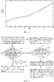
- the open circuit potential curve of the iron-lithium battery core is shown in FIG.2 .
- the open circuit potential curve of the ternary battery core is shown in FIG.3 .
- the slope of the open circuit potential curve of the iron-lithium battery core is greater than the slope of the open circuit potential curve of the ternary battery core under the state of charge of 0% to 8%, but the slope of the open circuit potential curve of the iron-lithium battery core is less than that of the ternary battery core under the state of charge of about 8% to 95%.
- the open circuit potential curve of the iron-lithium core shows a trend of steep rise and then smooth rise, the open circuit potential curve of the ternary core shows a trend of gradual rise.
- the power management controller 30 can collect the state parameters of each first battery cell 101 in the first battery core 10 and each second battery cell 201 in the second battery core 20, such as charging voltage, open circuit voltage, etc.
- the power management controller 30 can be directly connected to each battery cell via a wire or cable and collect the state parameters of each battery cell.
- the power management controller may not be directly connected to each battery cell, but rather collect the state parameters of each battery cell via wireless transmission technology.
- the battery module 1 can also include more components.
- it can also include a plurality of equalization units 40, each the equalization units 40 is disposed on one battery cell, and the power management controller 30 and each equalization unit 40 are electrically connected to control the equalization unit to perform equalization processing on the corresponding battery cell, where the equalization unit 40 can be a loss circuit, which can be used to lose the power of the connected battery cell under the control of the power management controller 30.
- the application scheme provides a method for equalizing a battery module, which is used to equalize the aforementioned battery modules with different kinds of battery cores.
- the execution subject of this method can be the power management controller in the battery module.
- the method includes the following steps:
- the power management controller can obtain a first charging voltage of each battery cell in the first battery core and a second charging voltage of each battery cell in the second battery core during charging. Furthermore, the power management controller can obtain the maximum and minimum value of the first charging voltage in the first battery core, and the maximum and minimum value of the second charging voltage in the second battery core.
- the first preset value can be determined according to the fully-charged voltage of the first battery core minus the first set value
- the second preset value can be determined according to fully-charged voltage of the second battery core minus the second set value, thus it can determine whether the first battery core enters its corresponding first fully-charged interval according to whether the maximum value of the first charging voltage in the first battery core is greater than the first preset value.
- the maximum value of the first charging voltage is greater than the first preset value, it indicates that the first battery core is close to the state of fully-charged and enters the corresponding first fully-charged interval.
- the maximum value of the first charging voltage is less than the first preset value, it indicates that the first battery core isn't still close to the state of fully-charged and doesn't enter the corresponding first fully-charged interval.
- whether the second battery core enters its corresponding second fully-charged interval can be determined according to whether the maximum value of the second charging voltage in the second battery core is greater than the second preset value.
- the first battery core and the second battery core are different kinds of battery core s, the scopes of their fully-charged range interval are also different. Therefore, the first preset value and the second preset value in an embodiment of the application can be designed as different. Of course, it doesn't exclude some special circumstances where the fully-charged voltage of the first battery core minus the first set value is just the same as the fully-charged voltage of the second battery core minus the second set value. Such special circumstances are also within the scope of protection of this application.
- step S402 the first battery core has entered its corresponding first fully-charged interval, indicating that the first battery core has nearly reached fully charged, and at this time, the second battery core has not yet entered its corresponding second fully-charged interval indicating that the second battery core still has not reached a state of fully-charged.
- the first battery core is discharged so that the power capacity charged in the first battery core is consumed under a certain extent, and then it slows down the charging speed of the first battery core until the second battery core enters its corresponding second fully-charged interval, and stops discharging consumption on the first battery core and the equalization comes to an end.
- the first battery core is discharged in step S402 until the second battery core enters its corresponding second fully-charged interval, and it can be implemented as follows, as shown in FIG.5 , including:
- partial battery cells are selected in a plurality of battery cells in the first battery core to perform discharging, and realizes the first battery core is discharged.
- the target battery cell is discharged in step S501 means charging of the target battery cell while and the discharge consumption is performed, for example, loss circuit is used to consume the charge of the target battery cell and so on.
- the target cell in step 500 can be randomly selected according to the preset number.
- the following method will be introduced to select target battery cell based on the charging voltage of a plurality of battery cells in the first battery core. As shown in FIG.6 , the method includes the following steps:
- the first charging voltage is greater than the fourth preset value indicates that the charging voltage of the corresponding battery cell is higher than the rest of battery cells, in order to make different battery cells in the first battery core voltage tends to be consistent, and therefore, select the battery cell whose the first charging voltage is greater than the fourth preset value to discharge.
- C is the fourth preset value
- A is the full-charged voltage pressure of the first battery core
- B is the voltage difference value
- a and b are constants.
- Step S501 can include the following steps:
- the present embodiment can find that the battery module enters a equalization state in time, and stop discharging the battery cell to save electric energy.
- the third preset value is determined by the fully-charged voltage of the first battery core and the third set value.
- the third preset value is smaller than the first preset value, and thus when the maximum value of the first charging voltage in the first battery core is less than the third preset value, it indicates that there has a not small voltage difference from which the first battery core enters the fully-charged interval; when the maximum value of the first charging voltage in the first battery core is greater than the third preset value, it indicates that there has a small voltage difference from which the first battery core enters the fully-charged interval;
- step S403 proceeds to step S404, and the second battery core is discharged until the first battery core enters its corresponding first fully-charged interval.
- the process of discharging the first battery core can be referred to step S402, and details are not described again.
- step S403 When a larger voltage difference from which the first battery core enters the fully-charged interval is determined by step S403, if step S404 is still performed to discharge the second battery core, and then the second battery core need a longer time to discharge, which is not unfriendly to charge the second battery core and the overall charging time of the battery module is also longer.
- the application provides the following battery method for equalizing.
- step S405 is performed to rest the first battery core and the second battery core, and stop charging the first battery core and the second battery core during the period of resting. Its purpose is to obtain the open circuit voltage of each battery cell in the first battery core or the second battery core under the state of resting, and then find the SOC corresponding to each battery cell in the open circuit potential curve corresponding to the battery cell based on the open circuit voltage, where SOC refers to the state of charge of a battery cell, which can be found through the open circuit voltage and open circuit potential curve. For example, the open circuit voltage (ordinate) of some battery cell and the open circuit potential curve are obtained in FIG.2 . Then the corresponding SOC (abscissa) of the open circuit voltage can be obtained.
- the resting time can be set according to experience, or, the resting time can also be set according to parameters such as the temperature of the first core and the second battery core, voltage of the battery core.
- step S406 is performed to discharge both the first battery core and the second battery core after resting until the SOC of each battery cell in the first battery core and the second battery core enters the same state, and realizes the equalization between the first battery core and the second battery core, where the SOC of each battery cell in the first battery core and the second battery core enters the same state, means that the SOC in the first battery core and the second battery core are the same or although the difference exists but the difference is within a preset range, and the preset range can be set to a smaller range, for example, the preset range is that the SOC difference between the first battery core and the second battery core is within 10%.
- step S406 may includes the following steps:
- step S700 since the first battery core and the second battery core have stopped being charged, the SOC value of each battery cell in the first battery core can be calculated according to the open circuit voltage of each battery cell in the first battery core and the first open circuit potential curve of the first battery core, and then the minimum SOC value among the SOC values of each battery cell in the first battery core.
- step S701 each battery cell other than the battery cell corresponding to a minimum SOC value in the first battery core are discharged until the SOC of these battery cores drops to the minimum SOC value, and realize the alignment of each battery core in the first battery core.
- the discharge capacity is determined according to the minimum SOC value in the first battery core and the discharge capacity, and it is used to discharge capacity each battery core in the second battery core.
- the discharge capacity can be calculated according to the minimum SOC value of the first battery core and the rated capacity of the second battery core.
- the discharge capacity of the second battery core that needs to be discharged can be obtained through the minimum SOC value of the first battery core so that the SOC of the second battery core is close to the minimum SOC of the first battery core after the second battery core is discharged based on the discharge capacity. Finally, the first battery core and the second battery core are under more equalized state.
- FIG.8 shows a schematic structural diagram of an equalizing apparatus of a battery module provided by an embodiment of the application.
- the apparatus corresponds to the method embodiment executed by the power management controller in FIG.4 to FIG.7 and can execute the steps involved in the method executed by the power management controller in the above embodiment.
- the apparatus includes at least one software function module, the at least one software function module can be stored in a memory in the form of software or firmware, or can be solidified in an operating system(operating system, OS) of the apparatus.
- the apparatus includes: an obtaining module 800, configured to obtain a first charging voltage of each battery cell in the first battery core and a second charging voltage of each battery cell in the second battery core; a judgment module 801, configured to judge whether a maximum value of the first charging voltage of each battery cell in the first battery core is greater than a first preset value to determine whether the first battery core enters its corresponding first fully-charged interval, and judge whether a maximum value of the second charging voltage of each battery cell in the second battery core is greater than a second preset value to determine whether the second battery core enters its corresponding second fully-charged interval; a discharge module 802, configured to discharge the first battery core until the second battery core enters its corresponding second fully-charged interval after the judgment module 801 judges that the first battery core enters its corresponding first fully-charged interval and the second battery core doesn't enter its corresponding second fully-charged interval; the obtaining module 800, is configured to obtain a maximum value of the first charging voltage after the judgment module 801 judges that the first battery core doesn't enter
- the discharge module 802 is specifically configured to determine at least one target battery cell according to the first charging voltage of each battery cell in the first battery core; and to discharge at least one target battery cell until the second battery core enters its corresponding fully-charged interval.
- the discharge module 802 is further configured to obtain a SOC value of each battery cell in the first battery core after resting the preset time; and discharge each battery cell other than the battery cell corresponding to a minimum SOC value in the first battery core, so that the SOC value of each battery cell in the first battery core is equal to the minimum SOC value; and determine a discharge capacity according to the minimum SOC value; and discharge each battery cell in the second battery core according to the discharge capacity.
- the equalizing apparatus of the above battery module can adopt different equalization strategies according to the difference between the two different kinds of battery cores in the battery module entering the full charging interval, and improve equalizing accuracy of the two different kinds of battery cores in the battery module in order to avoid the occurrence of overcharge/overdischarge, and further to improve the life of the battery module.
- the implementation of each module in the equalizing apparatus of the battery module can refer to the implementation of the corresponding steps in the method for equalizing the battery module.
- the present application provides a power management controller.
- the power management controller has a chip 9, and an instruction is solidified in the chip 9.
- the instruction is executed by the chip to execute the equalizing method according to any one of optional implementation manners of the first aspect and any one of an optional implementation manner of the first aspect.
- the chip 9 specifically includes: a processor 901 and a memory 902.
- the processor 901 and the memory 902 are interconnected through a communication bus 903 and/or other forms of connection mechanism (not shown) and communicate with each other.
- the memory 902 stores a computer program executable by the processor 901.
- the processor 901 executes the computer program to execute the method process in any one of the foregoing implementation manners during execution, such as step S400 to step S406: obtaining a first charging voltage of each battery cell in the first battery core and a second charging voltage of each battery cell in the second battery core; judging whether the first battery core enters its corresponding first fully-charged interval and judging whether the second battery core enters its corresponding second fully-charged interval; if the first battery core enters its corresponding first fully-charged interval and the second battery core doesn't enter its corresponding second fully-charged interval, discharging the second battery core by the power management controller until the first battery core enters its corresponding first fully-charged interval; if the first battery core doesn't enter its corresponding first fully-charged interval and the second battery core enters its corresponding second fully-charged interval, judging whether the maximum value of the first charging voltage of each battery cell in the first battery core is greater than a third preset value; if so, discharging the
- the present application provides a storage medium with a computer-executable instruction stored therein, the computer-executable instruction executes the steps in any one of an optional implementations the above-mentioned equalizing method, when executed by the processor.
- the storage medium can be implemented by any type of volatile or nonvolatile storage apparatuses or their combination, such as Static Random Access Memory(Static Random Access Memory, SRAM), Electrically Erasable Programmable Read-Only Memory(Electrically Erasable Programmable Read-Only Memory, EEPROM), Erasable Programmable Read Only Memory(Erasable Programmable Read Only Memory, EPROM), Programmable Read-Only Memory(Programmable Read-Only Memory, PROM), Read-Only Memory(Read-Only Memory, ROM), magnetic memory, flash memory, magnetic disk or optical disk.
- Static Random Access Memory Static Random Access Memory, SRAM
- Electrically Erasable Programmable Read-Only Memory Electrically Erasable Programmable Read-Only Memory
- EEPROM Electrically Erasable Programmable Read-Only Memory
- EPROM Erasable Programmable Read Only Memory
- PROM Programmable Read-Only Memory
- Read-Only Memory Read-Only Memory
- magnetic memory flash memory
- flash memory magnetic disk
- the present application provides a computer program product, the computer program product, when executed by a computer, causes the computer to execute the method process in any of the foregoing implementation manners.
Priority Applications (1)
| Application Number | Priority Date | Filing Date | Title |
|---|---|---|---|
| HUE20923689A HUE062267T2 (hu) | 2020-12-30 | 2020-12-30 | Akkumulátormodul kiegyenlítésére szolgáló eljárás és készülék, akkumulátormodul és teljesítménykezelõ vezérlõ |
Applications Claiming Priority (1)
| Application Number | Priority Date | Filing Date | Title |
|---|---|---|---|
| PCT/CN2020/141793 WO2022141292A1 (fr) | 2020-12-30 | 2020-12-30 | Procédé et dispositif d'égalisation pour module de batterie, module de batterie et dispositif de commande de gestion d'alimentations électriques |
Publications (3)
| Publication Number | Publication Date |
|---|---|
| EP4050697A4 EP4050697A4 (fr) | 2022-08-31 |
| EP4050697A1 true EP4050697A1 (fr) | 2022-08-31 |
| EP4050697B1 EP4050697B1 (fr) | 2023-06-14 |
Family
ID=82117903
Family Applications (1)
| Application Number | Title | Priority Date | Filing Date |
|---|---|---|---|
| EP20923689.2A Active EP4050697B1 (fr) | 2020-12-30 | 2020-12-30 | Procédé et dispositif d'égalisation d'un module de batterie, module de batterie, et contrôleur de gestion de puissance |
Country Status (5)
| Country | Link |
|---|---|
| US (1) | US11557903B2 (fr) |
| EP (1) | EP4050697B1 (fr) |
| CN (1) | CN114982039A (fr) |
| HU (1) | HUE062267T2 (fr) |
| WO (1) | WO2022141292A1 (fr) |
Families Citing this family (1)
| Publication number | Priority date | Publication date | Assignee | Title |
|---|---|---|---|---|
| EP4071885A4 (fr) * | 2021-02-09 | 2022-10-12 | Contemporary Amperex Technology Co., Limited | Procédé de charge de batterie, dispositif de commande, système de gestion de batterie, batterie et appareil électrique |
Family Cites Families (12)
| Publication number | Priority date | Publication date | Assignee | Title |
|---|---|---|---|---|
| JP2006304393A (ja) | 2005-04-15 | 2006-11-02 | Toyota Motor Corp | 電源装置およびその制御方法並びに車両 |
| KR100824905B1 (ko) * | 2006-08-24 | 2008-04-23 | 삼성에스디아이 주식회사 | 하이브리드 배터리 및 그것의 완전 충전 용량 계산 방법 |
| US8098041B2 (en) | 2007-11-04 | 2012-01-17 | GM Global Technology Operations LLC | Method of charging a powertrain |
| WO2012078624A2 (fr) * | 2010-12-06 | 2012-06-14 | Coda Automotive, Inc. | Circuits d'équilibrage d'élément électrochimique et procédés associés |
| WO2013019899A2 (fr) * | 2011-08-01 | 2013-02-07 | Maxim Integrated Products, Inc. | Circuits et procédés d'équilibrage simples et à haut rendement pour batteries hybrides |
| US9365115B2 (en) | 2012-01-20 | 2016-06-14 | Ford Global Technologies, Llc | System and method for vehicle power management |
| KR101500547B1 (ko) * | 2012-05-10 | 2015-03-09 | 주식회사 엘지화학 | 배터리 셀의 충전량 밸런싱 장치 및 방법 |
| CN102938570B (zh) * | 2012-10-23 | 2015-03-11 | 华为技术有限公司 | 供电系统及供电装置 |
| CN108988421B (zh) * | 2018-07-13 | 2020-06-30 | 维沃移动通信有限公司 | 一种电池的充电方法、充电电路以及终端 |
| EP3905476A4 (fr) | 2019-03-22 | 2022-04-20 | Guangdong Oppo Mobile Telecommunications Corp., Ltd. | Dispositif et procédé d'alimentation électrique, et dispositif électronique |
| EP3937292A4 (fr) * | 2019-03-22 | 2022-03-09 | Guangdong Oppo Mobile Telecommunications Corp., Ltd. | Procédé de commande de charge et de décharge et dispositif à charger |
| JP7147809B2 (ja) * | 2019-08-01 | 2022-10-05 | 株式会社デンソー | 二次電池の劣化度判定装置及び組電池 |
-
2020
- 2020-12-30 EP EP20923689.2A patent/EP4050697B1/fr active Active
- 2020-12-30 CN CN202080080430.2A patent/CN114982039A/zh active Pending
- 2020-12-30 HU HUE20923689A patent/HUE062267T2/hu unknown
- 2020-12-30 WO PCT/CN2020/141793 patent/WO2022141292A1/fr unknown
-
2021
- 2021-09-29 US US17/488,410 patent/US11557903B2/en active Active
Also Published As
| Publication number | Publication date |
|---|---|
| EP4050697A4 (fr) | 2022-08-31 |
| CN114982039A (zh) | 2022-08-30 |
| WO2022141292A1 (fr) | 2022-07-07 |
| US20220209547A1 (en) | 2022-06-30 |
| US11557903B2 (en) | 2023-01-17 |
| EP4050697B1 (fr) | 2023-06-14 |
| HUE062267T2 (hu) | 2023-10-28 |
Similar Documents
| Publication | Publication Date | Title |
|---|---|---|
| US10811886B2 (en) | Charge control apparatus capable of high speed cell balancing and energy saving and method thereof | |
| CN111293739B (zh) | 一种充电方法及装置 | |
| EP3923007B1 (fr) | Dispositif de gestion de batterie, procédé de gestion de batterie, bloc-batterie et véhicule électrique | |
| WO2021217314A1 (fr) | Procédé d'égalisation de batterie, batterie intelligente, système de charge et support de stockage | |
| WO2014065615A1 (fr) | Appareil et procédé d'estimation d'état de charge de batterie | |
| CN110509817B (zh) | 车辆及电池均衡的控制方法、装置 | |
| US20140239914A1 (en) | Battery controller | |
| WO2012091434A2 (fr) | Procédé et dispositif pour calculer l'état de santé d'une batterie secondaire | |
| KR20180079772A (ko) | 배터리 관리 장치 및 이를 이용한 lfp 셀의 과전압 보호 방법 | |
| WO2023077270A1 (fr) | Procédé d'égalisation de capacité de cellule de batterie, système de gestion de batterie et support de stockage | |
| US10756393B2 (en) | Method for preventing duplicate allocation of ID to battery modules | |
| EP4050697A1 (fr) | Procédé et dispositif d'égalisation pour module de batterie, module de batterie et dispositif de commande de gestion d'alimentations électriques | |
| WO2023122961A1 (fr) | Procédé et appareil d'étalonnage d'état pour batterie basse tension, et véhicule électrique | |
| CN117220384A (zh) | 一种电池并联运行的电流分配方法和电池并联系统 | |
| CN113541224A (zh) | 电池系统、电压平衡程序的控制方法与平衡电量的计算方法 | |
| CN113826259A (zh) | 电池库控制装置和方法 | |
| WO2022097931A1 (fr) | Dispositif et procédé de gestion de batteries | |
| WO2023123767A1 (fr) | Procédé et système de détermination d'un temps de charge de batterie restant | |
| JP2002135989A (ja) | 蓄電池の充放電制御方法 | |
| CN116118568A (zh) | 一种基于磷酸铁锂电池的均衡方法 | |
| CN113178926B (zh) | 用于通信基站均衡充放电控制方法及系统 | |
| KR102360012B1 (ko) | 배터리 시스템 및 배터리 시스템 제어 방법 | |
| KR101472886B1 (ko) | 전지팩의 전압 밸런싱 장치 및 방법 | |
| CN112068014A (zh) | 动力电池组的峰值功率预测方法、装置及电池管理系统 | |
| WO2022178672A1 (fr) | Procédé et appareil de commande de charge, et dispositif de commande de gestion d'énergie |
Legal Events
| Date | Code | Title | Description |
|---|---|---|---|
| STAA | Information on the status of an ep patent application or granted ep patent |
Free format text: STATUS: UNKNOWN |
|
| STAA | Information on the status of an ep patent application or granted ep patent |
Free format text: STATUS: THE INTERNATIONAL PUBLICATION HAS BEEN MADE |
|
| PUAI | Public reference made under article 153(3) epc to a published international application that has entered the european phase |
Free format text: ORIGINAL CODE: 0009012 |
|
| STAA | Information on the status of an ep patent application or granted ep patent |
Free format text: STATUS: REQUEST FOR EXAMINATION WAS MADE |
|
| 17P | Request for examination filed |
Effective date: 20210916 |
|
| A4 | Supplementary search report drawn up and despatched |
Effective date: 20220311 |
|
| AK | Designated contracting states |
Kind code of ref document: A1 Designated state(s): AL AT BE BG CH CY CZ DE DK EE ES FI FR GB GR HR HU IE IS IT LI LT LU LV MC MK MT NL NO PL PT RO RS SE SI SK SM TR |
|
| STAA | Information on the status of an ep patent application or granted ep patent |
Free format text: STATUS: EXAMINATION IS IN PROGRESS |
|
| 17Q | First examination report despatched |
Effective date: 20221006 |
|
| REG | Reference to a national code |
Ref country code: DE Ref legal event code: R079 Ref document number: 602020012623 Country of ref document: DE Free format text: PREVIOUS MAIN CLASS: H01M0010440000 Ipc: H02J0007000000 Ref country code: DE Ref legal event code: R079 Free format text: PREVIOUS MAIN CLASS: H01M0010440000 Ipc: H02J0007000000 |
|
| GRAP | Despatch of communication of intention to grant a patent |
Free format text: ORIGINAL CODE: EPIDOSNIGR1 |
|
| STAA | Information on the status of an ep patent application or granted ep patent |
Free format text: STATUS: GRANT OF PATENT IS INTENDED |
|
| RIC1 | Information provided on ipc code assigned before grant |
Ipc: B60L 58/22 20190101ALI20230303BHEP Ipc: B60L 58/21 20190101ALI20230303BHEP Ipc: B60L 58/13 20190101ALI20230303BHEP Ipc: H01M 50/51 20210101ALI20230303BHEP Ipc: H01M 10/44 20060101ALI20230303BHEP Ipc: H01M 10/42 20060101ALI20230303BHEP Ipc: H02J 7/34 20060101ALI20230303BHEP Ipc: H02J 7/00 20060101AFI20230303BHEP |
|
| DAV | Request for validation of the european patent (deleted) | ||
| DAX | Request for extension of the european patent (deleted) | ||
| RIN1 | Information on inventor provided before grant (corrected) |
Inventor name: LI, SHICHAO Inventor name: ZHANG, SHICHANG Inventor name: XU, GUANGYU Inventor name: PENG, LEI |
|
| INTG | Intention to grant announced |
Effective date: 20230404 |
|
| GRAS | Grant fee paid |
Free format text: ORIGINAL CODE: EPIDOSNIGR3 |
|
| GRAA | (expected) grant |
Free format text: ORIGINAL CODE: 0009210 |
|
| STAA | Information on the status of an ep patent application or granted ep patent |
Free format text: STATUS: THE PATENT HAS BEEN GRANTED |
|
| AK | Designated contracting states |
Kind code of ref document: B1 Designated state(s): AL AT BE BG CH CY CZ DE DK EE ES FI FR GB GR HR HU IE IS IT LI LT LU LV MC MK MT NL NO PL PT RO RS SE SI SK SM TR |
|
| REG | Reference to a national code |
Ref country code: CH Ref legal event code: EP |
|
| P01 | Opt-out of the competence of the unified patent court (upc) registered |
Effective date: 20230516 |
|
| REG | Reference to a national code |
Ref country code: DE Ref legal event code: R096 Ref document number: 602020012623 Country of ref document: DE |
|
| REG | Reference to a national code |
Ref country code: AT Ref legal event code: REF Ref document number: 1579951 Country of ref document: AT Kind code of ref document: T Effective date: 20230715 |
|
| REG | Reference to a national code |
Ref country code: LT Ref legal event code: MG9D |
|
| REG | Reference to a national code |
Ref country code: NL Ref legal event code: MP Effective date: 20230614 |
|
| REG | Reference to a national code |
Ref country code: HU Ref legal event code: AG4A Ref document number: E062267 Country of ref document: HU |
|
| PG25 | Lapsed in a contracting state [announced via postgrant information from national office to epo] |
Ref country code: SE Free format text: LAPSE BECAUSE OF FAILURE TO SUBMIT A TRANSLATION OF THE DESCRIPTION OR TO PAY THE FEE WITHIN THE PRESCRIBED TIME-LIMIT Effective date: 20230614 Ref country code: NO Free format text: LAPSE BECAUSE OF FAILURE TO SUBMIT A TRANSLATION OF THE DESCRIPTION OR TO PAY THE FEE WITHIN THE PRESCRIBED TIME-LIMIT Effective date: 20230914 Ref country code: ES Free format text: LAPSE BECAUSE OF FAILURE TO SUBMIT A TRANSLATION OF THE DESCRIPTION OR TO PAY THE FEE WITHIN THE PRESCRIBED TIME-LIMIT Effective date: 20230614 |
|
| REG | Reference to a national code |
Ref country code: AT Ref legal event code: MK05 Ref document number: 1579951 Country of ref document: AT Kind code of ref document: T Effective date: 20230614 |
|
| PG25 | Lapsed in a contracting state [announced via postgrant information from national office to epo] |
Ref country code: RS Free format text: LAPSE BECAUSE OF FAILURE TO SUBMIT A TRANSLATION OF THE DESCRIPTION OR TO PAY THE FEE WITHIN THE PRESCRIBED TIME-LIMIT Effective date: 20230614 Ref country code: NL Free format text: LAPSE BECAUSE OF FAILURE TO SUBMIT A TRANSLATION OF THE DESCRIPTION OR TO PAY THE FEE WITHIN THE PRESCRIBED TIME-LIMIT Effective date: 20230614 Ref country code: LV Free format text: LAPSE BECAUSE OF FAILURE TO SUBMIT A TRANSLATION OF THE DESCRIPTION OR TO PAY THE FEE WITHIN THE PRESCRIBED TIME-LIMIT Effective date: 20230614 Ref country code: LT Free format text: LAPSE BECAUSE OF FAILURE TO SUBMIT A TRANSLATION OF THE DESCRIPTION OR TO PAY THE FEE WITHIN THE PRESCRIBED TIME-LIMIT Effective date: 20230614 Ref country code: HR Free format text: LAPSE BECAUSE OF FAILURE TO SUBMIT A TRANSLATION OF THE DESCRIPTION OR TO PAY THE FEE WITHIN THE PRESCRIBED TIME-LIMIT Effective date: 20230614 Ref country code: GR Free format text: LAPSE BECAUSE OF FAILURE TO SUBMIT A TRANSLATION OF THE DESCRIPTION OR TO PAY THE FEE WITHIN THE PRESCRIBED TIME-LIMIT Effective date: 20230915 |
|
| PG25 | Lapsed in a contracting state [announced via postgrant information from national office to epo] |
Ref country code: FI Free format text: LAPSE BECAUSE OF FAILURE TO SUBMIT A TRANSLATION OF THE DESCRIPTION OR TO PAY THE FEE WITHIN THE PRESCRIBED TIME-LIMIT Effective date: 20230614 |
|
| PG25 | Lapsed in a contracting state [announced via postgrant information from national office to epo] |
Ref country code: SK Free format text: LAPSE BECAUSE OF FAILURE TO SUBMIT A TRANSLATION OF THE DESCRIPTION OR TO PAY THE FEE WITHIN THE PRESCRIBED TIME-LIMIT Effective date: 20230614 |
|
| PG25 | Lapsed in a contracting state [announced via postgrant information from national office to epo] |
Ref country code: IS Free format text: LAPSE BECAUSE OF FAILURE TO SUBMIT A TRANSLATION OF THE DESCRIPTION OR TO PAY THE FEE WITHIN THE PRESCRIBED TIME-LIMIT Effective date: 20231014 |
|
| PG25 | Lapsed in a contracting state [announced via postgrant information from national office to epo] |
Ref country code: SM Free format text: LAPSE BECAUSE OF FAILURE TO SUBMIT A TRANSLATION OF THE DESCRIPTION OR TO PAY THE FEE WITHIN THE PRESCRIBED TIME-LIMIT Effective date: 20230614 Ref country code: SK Free format text: LAPSE BECAUSE OF FAILURE TO SUBMIT A TRANSLATION OF THE DESCRIPTION OR TO PAY THE FEE WITHIN THE PRESCRIBED TIME-LIMIT Effective date: 20230614 Ref country code: RO Free format text: LAPSE BECAUSE OF FAILURE TO SUBMIT A TRANSLATION OF THE DESCRIPTION OR TO PAY THE FEE WITHIN THE PRESCRIBED TIME-LIMIT Effective date: 20230614 Ref country code: PT Free format text: LAPSE BECAUSE OF FAILURE TO SUBMIT A TRANSLATION OF THE DESCRIPTION OR TO PAY THE FEE WITHIN THE PRESCRIBED TIME-LIMIT Effective date: 20231016 Ref country code: IS Free format text: LAPSE BECAUSE OF FAILURE TO SUBMIT A TRANSLATION OF THE DESCRIPTION OR TO PAY THE FEE WITHIN THE PRESCRIBED TIME-LIMIT Effective date: 20231014 Ref country code: EE Free format text: LAPSE BECAUSE OF FAILURE TO SUBMIT A TRANSLATION OF THE DESCRIPTION OR TO PAY THE FEE WITHIN THE PRESCRIBED TIME-LIMIT Effective date: 20230614 Ref country code: CZ Free format text: LAPSE BECAUSE OF FAILURE TO SUBMIT A TRANSLATION OF THE DESCRIPTION OR TO PAY THE FEE WITHIN THE PRESCRIBED TIME-LIMIT Effective date: 20230614 Ref country code: AT Free format text: LAPSE BECAUSE OF FAILURE TO SUBMIT A TRANSLATION OF THE DESCRIPTION OR TO PAY THE FEE WITHIN THE PRESCRIBED TIME-LIMIT Effective date: 20230614 |
|
| PGFP | Annual fee paid to national office [announced via postgrant information from national office to epo] |
Ref country code: FR Payment date: 20231108 Year of fee payment: 4 Ref country code: DE Payment date: 20231107 Year of fee payment: 4 Ref country code: HU Payment date: 20231121 Year of fee payment: 4 |
|
| PG25 | Lapsed in a contracting state [announced via postgrant information from national office to epo] |
Ref country code: PL Free format text: LAPSE BECAUSE OF FAILURE TO SUBMIT A TRANSLATION OF THE DESCRIPTION OR TO PAY THE FEE WITHIN THE PRESCRIBED TIME-LIMIT Effective date: 20230614 |
|
| PLBE | No opposition filed within time limit |
Free format text: ORIGINAL CODE: 0009261 |
|
| STAA | Information on the status of an ep patent application or granted ep patent |
Free format text: STATUS: NO OPPOSITION FILED WITHIN TIME LIMIT |