EP4049864B1 - System zur schätzung der reifenverschleissmenge, programm zur schätzung der reifenverschleissmenge und verfahren zur schätzung der reifenverschleissmenge - Google Patents
System zur schätzung der reifenverschleissmenge, programm zur schätzung der reifenverschleissmenge und verfahren zur schätzung der reifenverschleissmenge Download PDFInfo
- Publication number
- EP4049864B1 EP4049864B1 EP20878250.8A EP20878250A EP4049864B1 EP 4049864 B1 EP4049864 B1 EP 4049864B1 EP 20878250 A EP20878250 A EP 20878250A EP 4049864 B1 EP4049864 B1 EP 4049864B1
- Authority
- EP
- European Patent Office
- Prior art keywords
- tire
- wear
- strain
- tread portion
- wear amount
- Prior art date
- Legal status (The legal status is an assumption and is not a legal conclusion. Google has not performed a legal analysis and makes no representation as to the accuracy of the status listed.)
- Active
Links
Images


Classifications
-
- B—PERFORMING OPERATIONS; TRANSPORTING
- B60—VEHICLES IN GENERAL
- B60C—VEHICLE TYRES; TYRE INFLATION; TYRE CHANGING; CONNECTING VALVES TO INFLATABLE ELASTIC BODIES IN GENERAL; DEVICES OR ARRANGEMENTS RELATED TO TYRES
- B60C11/00—Tyre tread bands; Tread patterns; Anti-skid inserts
- B60C11/24—Wear-indicating arrangements
- B60C11/243—Tread wear sensors, e.g. electronic sensors
-
- B—PERFORMING OPERATIONS; TRANSPORTING
- B60—VEHICLES IN GENERAL
- B60C—VEHICLE TYRES; TYRE INFLATION; TYRE CHANGING; CONNECTING VALVES TO INFLATABLE ELASTIC BODIES IN GENERAL; DEVICES OR ARRANGEMENTS RELATED TO TYRES
- B60C11/00—Tyre tread bands; Tread patterns; Anti-skid inserts
- B60C11/24—Wear-indicating arrangements
- B60C11/246—Tread wear monitoring systems
-
- B—PERFORMING OPERATIONS; TRANSPORTING
- B60—VEHICLES IN GENERAL
- B60C—VEHICLE TYRES; TYRE INFLATION; TYRE CHANGING; CONNECTING VALVES TO INFLATABLE ELASTIC BODIES IN GENERAL; DEVICES OR ARRANGEMENTS RELATED TO TYRES
- B60C19/00—Tyre parts or constructions not otherwise provided for
-
- B—PERFORMING OPERATIONS; TRANSPORTING
- B60—VEHICLES IN GENERAL
- B60C—VEHICLE TYRES; TYRE INFLATION; TYRE CHANGING; CONNECTING VALVES TO INFLATABLE ELASTIC BODIES IN GENERAL; DEVICES OR ARRANGEMENTS RELATED TO TYRES
- B60C23/00—Devices for measuring, signalling, controlling, or distributing tyre pressure or temperature, specially adapted for mounting on vehicles; Arrangement of tyre inflating devices on vehicles, e.g. of pumps or of tanks; Tyre cooling arrangements
- B60C23/02—Signalling devices actuated by tyre pressure
- B60C23/04—Signalling devices actuated by tyre pressure mounted on the wheel or tyre
- B60C23/0486—Signalling devices actuated by tyre pressure mounted on the wheel or tyre comprising additional sensors in the wheel or tyre mounted monitoring device, e.g. movement sensors, microphones or earth magnetic field sensors
-
- B—PERFORMING OPERATIONS; TRANSPORTING
- B60—VEHICLES IN GENERAL
- B60C—VEHICLE TYRES; TYRE INFLATION; TYRE CHANGING; CONNECTING VALVES TO INFLATABLE ELASTIC BODIES IN GENERAL; DEVICES OR ARRANGEMENTS RELATED TO TYRES
- B60C23/00—Devices for measuring, signalling, controlling, or distributing tyre pressure or temperature, specially adapted for mounting on vehicles; Arrangement of tyre inflating devices on vehicles, e.g. of pumps or of tanks; Tyre cooling arrangements
- B60C23/06—Signalling devices actuated by deformation of the tyre, e.g. tyre mounted deformation sensors or indirect determination of tyre deformation based on wheel speed, wheel-centre to ground distance or inclination of wheel axle
- B60C23/064—Signalling devices actuated by deformation of the tyre, e.g. tyre mounted deformation sensors or indirect determination of tyre deformation based on wheel speed, wheel-centre to ground distance or inclination of wheel axle comprising tyre mounted deformation sensors, e.g. to determine road contact area
-
- G—PHYSICS
- G01—MEASURING; TESTING
- G01M—TESTING STATIC OR DYNAMIC BALANCE OF MACHINES OR STRUCTURES; TESTING OF STRUCTURES OR APPARATUS, NOT OTHERWISE PROVIDED FOR
- G01M17/00—Testing of vehicles
- G01M17/007—Wheeled or endless-tracked vehicles
- G01M17/02—Tyres
-
- B—PERFORMING OPERATIONS; TRANSPORTING
- B60—VEHICLES IN GENERAL
- B60C—VEHICLE TYRES; TYRE INFLATION; TYRE CHANGING; CONNECTING VALVES TO INFLATABLE ELASTIC BODIES IN GENERAL; DEVICES OR ARRANGEMENTS RELATED TO TYRES
- B60C19/00—Tyre parts or constructions not otherwise provided for
- B60C2019/004—Tyre sensors other than for detecting tyre pressure
Definitions
- the present invention relates to a tire wear amount estimation system, a tire wear amount estimation program and a tire wear amount estimation method for estimating a wear state of a tread portion of a tire.
- an acceleration sensor mounted on inside surface of a pneumatic tire (tire) assembled to a rim wheel is used to detect acceleration (i.e., equivalent to centrifugal force) of tire radial direction, and the wear amount of the tire, specifically, the tread portion is estimated based on a time series waveform of the detected acceleration and a waveform obtained by differentiating the time series waveform.
- This technology focuses on the fact that the deformation speed of the tread portion at the time of ground contact changes as the tread portion wears.
- US2010186492A1 discloses an acceleration sensor installed on the inner surface in the inner liner region of a tire to detect the acceleration of the tread in the radial direction of the tire.
- the peak level on the leading edge side or the trailing edge side of the tread appearing in the differentiated waveform of the detected acceleration is calculated and used as an index of deformation speed of the tread.
- the degree of wear of the tire is estimated on the basis of the calculated index of deformation speed and an M-V map showing a predetermined relationship between the degree of tire wear and the index of deformation speed.
- JP2009061917A discloses an acceleration sensor provided on an inner surface side of an inner liner part of the tire. Acceleration of tread in the tire radial direction is detected to calculate and its differential waveform, and a grounding time t which is an interval between two peaks appearing in this differential wave form is calculated. A period of one peak is calculated as a rotation time, and a velocity of a tire is calculated from the rotation time T.
- JP2009019950A discloses an acceleration sensor provided on the inner surface side of an inner liner part of the tire, and an acceleration waveform in the tire diameter direction of a tire tread is detected, and a deformation time being a time between two peaks corresponding to a swelling point appearing in the acceleration waveform is calculated.
- a deformation length which is an index of a grounding out-of-plane deformation range of the tire is calculated, and a grounding time which is a time between two peaks corresponding to the ground contact end of the tread appearing in a differential waveform which is a time-series waveform of a differentiated value of the acceleration is calculated, and a grounding length which is an index of a deflection amount of the tire is calculated.
- the abrasion degree of the tire is estimated based on the calculated deformation length and grounding length and a map showing a relation between the deformation length corresponding to the abrasion degree of the tire and the grounding length, determined beforehand.
- US5749984A discloses a method and system for monitoring and measuring the amount of deflection of a pneumatic tire wherein said monitoring system in the tire detects tire sidewall deflection by measuring the length of the tire contact patch area relative to the total circumference of the tire.
- the embedded sensor device generates a signal which varies as it passes through the tire contact patch within the tire on a moving vehicle. If the vehicle is moving at a constant speed, the ratio of time which the sensor spends inside the contact patch to the time the sensor spends outside the contact patch is proportional to tire deflection. Sensor electrical signals are digitized and counted to determine deflection, tire speed and the number of tire revolutions to improve performance of both the tire and the vehicle.
- JP2007153034 discloses a judging part of the tire abrasion state judging device provides actual acceleration generated in the tire circumferential direction by an acceleration sensor when a rotating tire grounds. Additionally, it provides abrasion causing threshold value to be a standard for abrasion judgement set against standard acceleration generated in the tire circumferential direction from a memory part when the tire in a non-abrasion state grounds. The abrasion state of the tire is judged by comparing the detected actual acceleration and the abrasion causing threshold value with each other in accordance with at least either one of size of an output value of the acceleration, changing gradient of the output value and a peak interval in acceleration increase.
- Patent Literature 1 Japanese Patent Application Laid-Open No. 2016 -190615
- the present invention has been made in view of such a situation, and it is an object of the present invention to provide a tire wear amount estimation system, a tire wear amount estimation program, and a tire wear amount estimation method, which can achieve a high estimation accuracy of a wear amount even when traveling mainly at a low speed.
- FIG. 1 is an overall schematic configuration diagram of a tire wear amount estimation system 100 according to an embodiment. As shown in FIG. 1 , the tire wear amount estimation system 100 includes a sensor unit 110 and a processing device 120.
- the sensor unit 110 is provided in inside of a tread portion 20 of the pneumatic tire 10.
- FIG. 1 shows a cross-sectional shape of the pneumatic tire 10 assembled to a rim wheel 90 along a tire width direction.
- the tread portion 20 is a part in contact with the road surface R when the pneumatic tire 10 mounted on the vehicle (not shown) rolls on the road surface R (Not shown in FIG. 1 , see FIG. 4 ), and a tread pattern corresponding to the type of the vehicle and required performance is formed on the tread portion 20.
- the sensor unit 110 is preferably provided on each pneumatic tire mounted on the vehicle. However, the sensor unit 110 may not necessarily be provided in all pneumatic tires mounted on the vehicle.
- the sensor unit 110 is provided on inside surface of the pneumatic tire 10. Specifically, the sensor unit 110 is attached to a surface of an inner liner (not shown) for preventing leakage of a gas such as air filled in an internal space of the pneumatic tire 10 assembled to the rim wheel 90.
- the sensor unit 110 is not necessarily provided on inside surface of the pneumatic tire 10. For example, some or all of the sensor unit 110 may be embedded within the pneumatic tire 10.
- the sensor unit 110 is provided at the center of the tread portion 20 in the tire width direction.
- the sensor unit 110 may be provided at a place other than the tread portion 20, for example, the tire side portion 30.
- one sensor unit 110 is provided in the tire circumferential direction, but a plurality of sensor units 110 may be provided in the tire circumferential direction.
- the sensor unit 110 includes various sensors including a strain sensor, a battery, a wireless communication function, and the like.
- the processing device 120 realizes wireless communication with the sensor unit 110 and acquires a signal output from the sensor unit 110.
- the processing device 120 is implemented by hardware such as a communication module including a processor, memory, and antenna.
- the processing device 120 is usually provided in a vehicle to which the pneumatic tire 10 is mounted.
- the processing device 120 may be implemented by an electronic control unit (ECU) mounted on the vehicle.
- the processing device 120 may be implemented not on a vehicle but on a server computer (which may be referred to as a network cloud) connected via a wireless communication network.
- ECU electronice control unit
- server computer which may be referred to as a network cloud
- FIG. 2 is a functional block diagram of the tire wear amount estimation system 100. Specifically, FIG. 2 is a functional block diagram of the sensor unit 110 and the processing device 120.
- the sensor unit 110 includes an internal pressure sensor 111, a temperature sensor 113, a strain sensor 115, and a communication unit 117.
- the internal pressure sensor 111 detects the internal pressure (air pressure) of the pneumatic tire 10 assembled to the rim wheel 90.
- the temperature sensor 113 detects the temperature of the inner surface of the tread portion 20.
- the sensor unit 110 may not include the internal pressure sensor 111 and the temperature sensor 113. Alternatively, the sensor unit 110 may include an acceleration sensor.
- the strain sensor 115 detects strain generated in the tread portion 20. Specifically, the strain sensor 115 detects strain in the tire circumferential direction.
- the sensor unit 110 is provided on inside surface of the pneumatic tire 10, more specifically, the tread portion 20 (or inside the pneumatic tire 10), and the strain sensor 115 is also provided on inside surface of the tread portion 20 (or inside the pneumatic tire 10).
- the strain sensor 115 can detect the amount of strain (bending moment) generated when the tread portion 20 contacts the road surface R.
- the arcuate tread portion 20 in the tire side view is deformed substantially linearly by the load. Specifically, focusing on the position of the specific tread portion 20 in the tire circumferential direction, bending deformation occurs in the tread portion 20 at the timing of stepping on the road surface R, and the tread portion deforms substantially linearly in the state of contact with the road surface R. In addition, bending deformation occurs again at the timing of kicking out from the road surface R, and thereafter, the shape returns to the original arc shape.
- the stepping of the tread portion 20 onto the road surface R may be interpreted as a timing at which the predetermined position of the tread portion 20 in the tire circumferential direction is brought into contact with the road surface R by the rolling motion of the tread portion 20.
- the kicking out of the tread portion 20 from the road surface R may be interpreted as a timing at which the predetermined position of the tread portion 20 in the tire circumferential direction is separated from the road surface R by the rolling motion of the tread portion 20.
- the strain detected by the strain sensor 115 may correspond to the deformation amount ⁇ l when the load is applied divided by the original length l ( ⁇ l/l) as generally interpreted.
- the strain sensor 115 can output a voltage (unit: mV) corresponding to the microstrain ( ⁇ ).
- the amount of strain detected by the strain sensor 115 may be interpreted as a bend amount.
- the strain sensor 115 may be, for example, a piezoelectric sensor, but may be referred to as a strain sensor or a strain gauge.
- the number of elements constituting the strain sensor (gauge) and the gauge length are not particularly limited.
- the communication unit 117 executes wireless (radio) communication with the processing device 120.
- the wireless communication system of the communication unit 117 is not particularly limited. For example, as a communication scheme, a method using a frequency (such as UHF) used in a tire pressure monitoring system (TPMS) or the like, or a method in accordance with a short-range wireless communication standard can be mentioned.
- the communication unit 117 modulates the signals (voltage, etc.) output from the internal pressure sensor 111, the temperature sensor 113, and the strain sensor 115 according to a predetermined modulation scheme, and transmits the modulated signals to the processing device 120 via radio signals.
- the communication unit 117 may also transmit control data or the like transmitted from the processing device 120 via a radio signal to the internal pressure sensor 111, the temperature sensor 113, and the strain sensor 115 as necessary.
- the battery 119 supplies power necessary for the operation of the internal pressure sensor 111, the temperature sensor 113 and the strain sensor 115. More specifically, although the type of the battery 119 is not particularly limited, it is preferable that the sensor unit 110 is constituted by a primary battery or the like capable of being continuously driven for a long period of time (For example, one year or more).
- the processing device 120 includes a communication unit 121, a signal acquisition unit 123, a wear estimation unit 125, and an output unit 127.
- the communication unit 121 executes wireless communication with the sensor unit 110. Similar to the communication unit 117, the wireless communication system of the communication unit 121 is not particularly limited. Further, the communication unit 121 can perform communication with a control device such as an ECU of the vehicle to which the pneumatic tire 10 is mounted or with the outside of the vehicle via a wireless communication network.
- a control device such as an ECU of the vehicle to which the pneumatic tire 10 is mounted or with the outside of the vehicle via a wireless communication network.
- the signal acquisition unit 123 acquires a signal output from a sensor group constituting the sensor unit 110. Specifically, the signal acquisition unit 123 acquires signals output from the internal pressure sensor 111, the temperature sensor 113, and the strain sensor 115.
- the signal acquisition unit 123 acquires a strain signal output from the strain sensor 115.
- the signal acquisition unit 123 constitutes a strain signal acquisition unit.
- the signal acquisition unit 123 acquires a voltage value corresponding to the microstrain ( ⁇ ) detected by the strain sensor 115 as a strain signal.
- the signal acquisition unit 123 may directly acquire ⁇ as a strain signal if possible, such as when the strain sensor 115 or the communication unit 117 supports output of ⁇ .
- the wear estimation unit 125 estimates the wear state of the tread portion 20 using the strain signal ( ⁇ ) acquired by the signal acquisition unit 123.
- the wear state of the tread portion 20 estimated by the wear estimation unit 125 typically includes a wear amount (unit: mm) of the tread portion 20, but may also include a residual amount (residual groove amount) of a groove portion formed on the tread portion 20, a wear rate based on the pneumatic tire 10 when new (start of use), and the like. Alternatively, it may be an estimated travel distance (or time) until the pneumatic tire 10 reaches its use limit due to wear.
- the wear estimation unit 125 estimates the wear state of the tread portion 20 based on the strain signal (Bo) output at the timing of kicking out from the road surface R of the ground contact area Ac (see FIG. 3 ) of the tread portion 20 corresponding to the strain sensor 115 and the reference value of the strain signal.
- the wear estimation unit 125 uses the strain signal (Bi) output at the timing of stepping on the road surface of the ground contact area Ac as the reference value.
- the start time of estimating the wear state of the tread portion 20 is typically when the pneumatic tire 10 is new, but the start time of estimating the wear state of the tread portion 20 may also be used for the pneumatic tire 10 which has been used over a certain distance and the wear of the tread portion 20 has progressed to a certain extent.
- the wear estimation unit 125 can determine the estimated wear amount of the tread portion 20 based on the difference between the strain signal (Bo (w)) output at the timing of kicking out of the ground contact area Ac from the road surface R and the reference value, or the ratio between Bo (w) and the reference value.
- the wear estimation unit 125 determines the estimated wear amount of the tread portion 20 based on the difference between Bo (w) and the reference value.
- the wear estimation unit 125 determines the estimated wear amount of the tread portion 20 by associating the difference or the ratio with the wear amount (or the residual groove amount).
- the wear estimation unit 125 may adjust the estimated wear amount of the tread portion 20 using the ratio between the value of the strain signal (Bo (n)) when the pneumatic tire 10 is new and the above-mentioned reference value.
- the wear estimation unit 125 adjusts the ratio of Bo (n) to Bi (n) based on the value of the strain signal when the pneumatic tire 10 is new. Specifically, the wear estimation unit 125 adjusts the value of Bo (n)/Bi (n) based on the strain signal when the pneumatic tire 10 is new to "1" even when the value is other than "1" (such processing is called “offset processing").
- the wear estimation unit 125 adjusts all the values of Bo (n)/Bi (n) to "1 " based on the number of sensor units 110 that perform communication with the processing device 120, that is, the strain signals in the new state of tire corresponding to the number of pneumatic tires 10 mounted on the vehicle.
- the wear estimation unit 125 determines an estimated wear amount of the tread portion 20 on the basis of the ratio when the pneumatic tire 10 is new and the ratio when the pneumatic tire 10 is used for traveling a certain distance and worn.
- the wear estimation unit 125 may perform machine learning using the time-series waveform of the strain signal acquired by the signal acquisition unit 123. Specifically, the wear estimation unit 125 can create a wear estimation model by executing machine learning with the wear amount as an object variable using the feature amount relating to the peak value of the strain signal.
- the characteristic quantity relating to the peak value of the strain signal includes, for example, a ratio or difference between the peak value of the strain signal at the stepping timing and the kicking timing of the pneumatic tire 10, or a ratio or difference between the peak value of the strain signal at the kicking timing when the pneumatic tire 10 is new and when the wear is estimated. That is, the wear estimation unit 125 can execute machine learning by using "the amount of wear of the tread portion 20" as an objective variable and "an index value related to the size of the peak on the kick out side of the time-series waveform of the strain signal” as an explanatory variable.
- the index value may be any value (ratio or difference) related to the peak of the strain signal ( ⁇ ) output at the timing of kicking out related to the reference value.
- the feature amount may be estimated based on one time (one revolution) of time series waveforms, or the accuracy of estimating the wear state of the tread portion 20 may be enhanced by applying statistical methods such as average, median, and outlier processing based on a plurality of times of time series waveforms. Since the feature amount can vary depending on the type (Internal structure, tread pattern, etc.) of the pneumatic tire 10 and the tire size, it is preferable that the machine learning is executed for each type and tire size. By advancing such machine learning, it is possible to estimate the wear state of the tread portion 20 with high accuracy, for example, even in the case of a new tire size which has never been obtained before.
- the wear estimation unit 125 may increase the accuracy of estimating the wear state of the tread portion 20 by combining a signal output from the internal pressure sensor 111 or the temperature sensor 113 (or an acceleration sensor) with a strain signal.
- the wear estimation unit 125 may supplement or substitute the estimation of the wear state described above by using a learning model (wear estimation model) obtained by executing machine learning.
- the output unit 127 outputs information on the wear state of the tread portion 20 estimated by the wear estimation unit 125. More specifically, the output unit 127 can output the amount of wear of the tread portion 20, the amount of remaining grooves, the wear rate of the pneumatic tire 10 relative to the new one, and the running distance (or time) until the use limit is reached.
- the output unit 127 may display a warning (alert) on a display device provided in the vehicle indicating that the amount of wear (or the rate of wear) has exceeded a threshold, or that the amount of remaining grooves and the travel distance (or time) have fallen below the threshold, or may notify the warning by a voice guidance and/or an alarm sound.
- the output unit 127 may display or report information or a warning about the internal pressure or temperature based on signals from the internal pressure sensor 111 and the temperature sensor 113.
- the operation of the tire wear amount estimation system 100 will be described. Specifically, the operation of estimating the wear amount of the tread portion 20 by the tire wear amount estimation system 100 will be described.
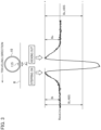
- FIG. 3 shows the pneumatic tire 10 provided with the strain sensor 115 and an example of output of a strain signal by the strain sensor 115. Specifically, FIG. 3 shows an example of a time-series waveform of microstrain ( ⁇ ) detected by the strain sensor 115 provided on inside surface of the pneumatic tire 10 (tread portion 20).
- a ground contact area Ac which is a part of inside surface of the tread portion 20 receives compressive stress at the stepping timing to the road surface R.
- Bi which is a strain in the compression direction ("+ " direction in the figure)
- the strain sensor 115 detects strain in the tire circumferential direction.
- the strain at the stepping timing is expressed as Bi
- the strain at the kicking timing is expressed as Bo.
- the strain of the pneumatic tire 10 when it is new is referred to as Bo (n) and Bi (n)
- the strain of the pneumatic tire 10 at an arbitrary time point in the use process (That is, when the wear state is estimated,) is referred to as Bo (w) and Bi (w).
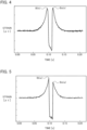
- FIG. 4 shows an output example of a strain signal when the pneumatic tire 10 is new.
- FIG. 5 shows an output example of a strain signal when the pneumatic tire 10 is worn.
- the wear amount estimation system 100 estimates the wear state of the tread portion 20 by utilizing such a feature that the peak value of the strain (Bo (w)) at the kicking out timing of inside surface of the tread portion 20 decreases by wear progress.
- FIG. 6 shows an estimation operation flow of the wear amount of the pneumatic tire 10 (tread portion 20) by the tire wear amount estimation system 100.
- the processing device 120 acquires a time series waveform of the strain signal ( ⁇ ) (S 10). More specifically, the processing device 120 acquires time series waveforms ( ⁇ ) as shown in FIG. 5 .
- the processing device 120 acquires time-series waveforms having peak values (Bi, Bo) of strain signals of the stepping timing and the kicking timing as shown in FIG. 5 for each rotation of the pneumatic tire 10.
- the processing device 120 may acquire one time-series waveform as shown in FIG. 5 to estimate the wear amount, but it is preferable to acquire a plurality of time-series waveforms to estimate the wear amount as described above.
- the processing device 120 detects the peak value (Bo (w)) of the strain signal of the kicking out timing by using the acquired time series waveform (S 20). Specifically, the processing device 120 detects the peak ⁇ of the kicking out timing based on the output (voltage) value from the strain sensor 115 corresponding to the peak of the kicking out timing strain signal.
- the processing device 120 compares the detected Bo (w) with a reference value (S 30). Specifically, the processing device 120 can use, as a reference value, a peak value (Bi (n) or Bi (w)) of the strain signal at the stepping timing.
- the processing device 120 estimates the wear amount of the tread portion 20 using the detected Bo (w) and any of the reference values described above (S 40).
- the processing device 120 can estimate the amount of wear of the tread portion 20 based on the difference between Bn (w) and the reference value or the ratio between Bn (w) and the reference value.
- the processing device 120 can estimate the amount of wear of the tread portion 20 based on any of the following.
- the processing device 120 may estimate not only the amount of wear of the tread portion 20, but also other parameters, specifically, the residual amount of groove, the wear rate of the pneumatic tire 10 relative to the new one, or the distance (or time) that can be traveled before the limit of use is reached.
- the processing device 120 may acquire information such as the accumulated travel distance and time from the ECU side of the vehicle, if necessary.
- the processing device 120 determines whether or not an alert is necessary based on the estimated wear amount (S 50). Specifically, the processing device 120 determines whether the wear amount (or wear rate) exceeds a threshold value. Alternatively, the processing device 120 may determine whether the residual groove amount and the travel distance (or time) described above are less than the threshold value.
- the processing device 120 If the estimated wear amount (or wear rate) exceeds a threshold value (Residual groove amount, running distance (or time) is below the threshold.), the processing device 120 outputs an alert (S 60).
- the processing device 120 may display the alert on a display device provided in the vehicle or may notify the alert by means of a voice guidance and/or an alarm sound.
- the wear amount estimation system 100 can estimate the wear amount of the tread portion 20 using a strain signal (Bo (w)) at the kicking out timing or the like, but the accuracy of estimating the wear amount may be enhanced by executing the offset processing as follows.
- the ratio of the strain signal when the pneumatic tire 10 is new is adjusted using the ratio of Bo (w) and the reference value as described above. For example, the value of Bo (n)/Bi (n) based on the strain signal (Bo (n)) when the pneumatic tire 10 is new is adjusted to "1".
- the processing device 120 can estimate the wear amount of the tread portion 20 based on the following calculation formula. Bo n ⁇ Bi n ⁇ Bo w / Bi w
- the processing device 120 can estimate the wear amount of the tread portion 20 based on the following calculation formula. Bo n / Bi n ⁇ Bo w / Bi w
- the wear state of the tread portion 20 can be estimated based on the strain signal (Bo) output at the timing of kicking out of the ground contact area Ac of the strain sensor 115 from the road surface R and the reference value (Bi or Bo (n)) of the strain signal.
- the strain signal shows the same tendency regardless of the traveling speed of the vehicle to which the pneumatic tire 10 is mounted, the amount of wear of the tread portion 20 can be estimated with high accuracy even when the vehicle is mainly traveling at a low speed (For example, about 40 km/h).
- the tire wear amount estimation system 100 even if the vehicle on which the pneumatic tire 10 is mounted is mainly driven at a low speed, a high estimation accuracy of the wear amount can be achieved.
- the strain sensor 115 Since the strain sensor 115 is more sensitive than the acceleration sensor, it picks up the irregularities of the road surface R, the dispersion of the peak on the tensile side at the time of grounding of the ground contact area Ac increases, and the dispersion of the wear feature amount, which is the gradient between the peak of the stepping (kicking out) timing and the peak at the time of grounding, also increases.
- a feature is found in which the peak value of the strain (Bo (w)) at the kicking out timing of inside surface of the tread portion 20 decreases with the wear progress, and the wear state of the tread portion 20 is estimated based on the feature.
- the tire wear amount estimation system 100 uses a strain signal (Bi (n) or Bi (w)) at the stepping timing as a reference value of the strain signal.
- the wear amount estimation system 100 can determine the estimated wear amount of the tread portion 20 based on the difference between the strain signal (Bo (w)) output at the timing of kicking out and the reference value (Bi (n), Bi (w)) or the ratio between Bo (w) and the reference value.
- the accuracy of estimating the wear state can be further enhanced.
- the ratio of Bo (w) to the reference value is used, the deterioration of the estimation accuracy due to individual differences between the strain sensor 115 and the pneumatic tire 10, variations in the internal pressure, and the like can be prevented.
- the wear amount estimation system 100 can adjust (calibrate) the estimated wear amount of the tread portion 20 by using the ratio between the value of the strain signal (Bo (n)) when the pneumatic tire 10 is new and the reference value.
- the specific wear amount (mm) and the residual groove amount (mm) can be estimated with high accuracy by executing such calibration.
- the strain sensor 115 detects strain in the tire circumferential direction, but the strain sensor 115 detects a strain in the tire width direction or tire radial direction, and the processing device 120 may estimate the wear state of the tread portion 20 based on the detected strain.
- the processing device 120 is realized on the ECU of a vehicle or on a server computer connected via a wireless communication network, but a part of the functional blocks constituting the processing device 120 may be provided on the ECU, and other functional blocks may be realized on the server computer.
- the main functions of the processing device 120 may also be provided as a software program executable in a computer.
- the software program may be provided over a communications network or recorded on a computer readable recording medium such as an optical disk, hard disk drive, or flash memory.
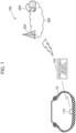
- FIG. 7 is an overall schematic configuration diagram of a tire wear amount estimation system 100 related to modified example.
- the processing device 120 (Some functions may be implemented by the ECU) mounted on a vehicle performs wireless communication with the sensor unit 110 mounted on the pneumatic tire 10, performs wireless communication with a wireless base station 200, and connects to a server computer 300 provided on a network cloud 400.
- the sensor unit 110 may extract the feature amount of the strain signal, specifically, Bo and Bi ( ⁇ ), and transmit only the extracted Bo and Bi to the processing device 120 instead of the data of the time series waveform.
- the functions of the processing device 120 described in the above-described embodiment may be mounted in the sensor unit 110.
Landscapes
- Engineering & Computer Science (AREA)
- Mechanical Engineering (AREA)
- Physics & Mathematics (AREA)
- General Physics & Mathematics (AREA)
- Tires In General (AREA)
Claims (6)
- System zur Schätzung des Reifenverschleißausmaßes (100), das Folgendes umfasst:eine Dehnungssignal-Erfassungseinheit (123), die ein Dehnungssignal erfasst, das von einem Dehnungssensor (115) ausgegeben wird, der auf einer Innenfläche eines Reifens (10) oder darin bereitgestellt wird, undeine Verschleißschätzungseinheit (125), die einen Verschleißzustand eines Laufflächenabschnitts (20) durch Vergleichen der Dehnungssignalausgabe (Bo(w)) zu einem Zeitpunkt des letzten Ablösens der Bodenberührungsfläche (Ac) des Laufflächenabschnitts, der dem Dehnungssensor entspricht, von einer Straßenoberfläche (R) mit einem Referenzwert des Dehnungssignals schätzt,wobei die Verschleißschätzungseinheit, als den Referenzwert, die Dehnungssignalausgabe (Bi(n), Bi(w)) zu einem Zeitpunkt des ersten Auftreffens der Bodenberührungsfläche auf der Straßenoberfläche verwendet.
- System zur Schätzung des Reifenverschleißausmaßes (100) nach Anspruch 1, wobei die Verschleißschätzungseinheit (125) ein geschätztes Verschleißausmaß des Laufflächenabschnitts (20) auf Grundlage einer Differenz zwischen einem Wert des Dehnungssignals, das zum Zeitpunkt des letzten Ablösens (Bo(w)) ausgegeben wird, und dem Referenzwert (Bi(n), Bi(w)) bestimmt.
- System zur Schätzung des Reifenverschleißausmaßes (100) nach Anspruch 1, wobei die Verschleißschätzungseinheit (125) ein geschätztes Verschleißausmaß des Laufflächenabschnitts (20) auf Grundlage eines Verhältnisses zwischen einem Wert des Dehnungssignals, das zum Zeitpunkt des letzten Ablösens (Bo(w)) ausgegeben wird, und dem Referenzwert (Bi(n), Bi(w)) bestimmt.
- System zur Schätzung des Reifenverschleißausmaßes (100) nach Anspruch 2 oder 3, wobei die Verschleißschätzungseinheit (125) das geschätzte Verschleißausmaß durch Verwenden eines Verhältnisses zwischen dem Wert des Dehnungssignals, das zum Zeitpunkt des letzten Ablösens ausgegeben wird, wenn der Reifen neu ist, (Bo(n)) und dem Referenzwert (Bi(n), Bi(w)) anpasst.
- Programm zur Schätzung des Reifenverschleißausmaßes, um zu veranlassen, dass ein Rechner ein Programm ausführt, das die folgenden Prozesse umfasst:einen Dehnungssignal-Erfassungsprozess zum Erfassen eines Dehnungssignals, das von einem Dehnungssensor (115) ausgegeben wird, der auf einer Innenfläche eines Reifens (10) oder darin bereitgestellt wird, undeinen Verschleißschätzungsprozess zum Schätzen eines Verschleißzustandes eines Laufflächenabschnitts (20) durch Vergleichen der Dehnungssignalausgabe (Bo(w)) zu einem Zeitpunkt des letzten Ablösens der Bodenberührungsfläche (Ac) des Laufflächenabschnitts, der dem Dehnungssensor entspricht, von einer Straßenoberfläche (R) mit einem Referenzwert des Dehnungssignals,wobei der Referenzwert die Dehnungssignalausgabe (Bi(n), Bi(w)) zu einem Zeitpunkt des ersten Auftreffens der Bodenberührungsfläche auf der Straßenoberfläche ist.
- Verfahren zur Schätzung des Reifenverschleißausmaßes, das die folgenden Schritte umfasst:Erfassen eines Dehnungssignals, das von einem Dehnungssensor (115) ausgegeben wird, der auf einer Innenfläche eines Reifens (10) oder darin bereitgestellt wird, undSchätzen eines Verschleißzustandes eines Laufflächenabschnitts (20) durch Vergleichen der Dehnungssignalausgabe (Bo(w)) zu einem Zeitpunkt des letzten Ablösens der Bodenberührungsfläche (Ac) des Laufflächenabschnitts, der dem Dehnungssensor entspricht, von einer Straßenoberfläche (R) mit einem Referenzwert des Dehnungssignals,wobei der Referenzwert die Dehnungssignalausgabe (Bi(n), Bi(w)) zu einem Zeitpunkt des ersten Auftreffens der Bodenberührungsfläche auf der Straßenoberfläche ist.
Applications Claiming Priority (2)
| Application Number | Priority Date | Filing Date | Title |
|---|---|---|---|
| JP2019191796A JP7425579B2 (ja) | 2019-10-21 | 2019-10-21 | タイヤ摩耗量推定システム、タイヤ摩耗量推定プログラム及びタイヤ摩耗量推定方法 |
| PCT/JP2020/039204 WO2021079838A1 (ja) | 2019-10-21 | 2020-10-19 | タイヤ摩耗量推定システム、タイヤ摩耗量推定プログラム及びタイヤ摩耗量推定方法 |
Publications (3)
| Publication Number | Publication Date |
|---|---|
| EP4049864A1 EP4049864A1 (de) | 2022-08-31 |
| EP4049864A4 EP4049864A4 (de) | 2023-11-01 |
| EP4049864B1 true EP4049864B1 (de) | 2025-06-04 |
Family
ID=75620518
Family Applications (1)
| Application Number | Title | Priority Date | Filing Date |
|---|---|---|---|
| EP20878250.8A Active EP4049864B1 (de) | 2019-10-21 | 2020-10-19 | System zur schätzung der reifenverschleissmenge, programm zur schätzung der reifenverschleissmenge und verfahren zur schätzung der reifenverschleissmenge |
Country Status (5)
| Country | Link |
|---|---|
| US (1) | US20220371382A1 (de) |
| EP (1) | EP4049864B1 (de) |
| JP (1) | JP7425579B2 (de) |
| CN (1) | CN114585523B (de) |
| WO (1) | WO2021079838A1 (de) |
Families Citing this family (12)
| Publication number | Priority date | Publication date | Assignee | Title |
|---|---|---|---|---|
| US10875539B2 (en) * | 2018-08-22 | 2020-12-29 | Infineon Technologies Ag | Tire load estimation |
| US11498371B2 (en) * | 2018-12-12 | 2022-11-15 | The Goodyear Tire & Rubber Company | Tire data information system |
| JP7368181B2 (ja) * | 2019-10-29 | 2023-10-24 | Toyo Tire株式会社 | 摩耗量推定システムおよび演算モデル生成システム |
| JP7483124B2 (ja) * | 2021-03-16 | 2024-05-14 | 日立Astemo株式会社 | 物理量検出装置 |
| US20230011981A1 (en) * | 2021-07-08 | 2023-01-12 | Volvo Car Corporation | Real-time tire monitoring system |
| JP7671651B2 (ja) * | 2021-08-10 | 2025-05-02 | 日産自動車株式会社 | 音質判定装置、音質判定方法、及び、音質判定プログラム |
| JP7735418B2 (ja) * | 2021-10-21 | 2025-09-08 | Astemo株式会社 | 物理量検出装置 |
| JP7761474B2 (ja) * | 2021-12-23 | 2025-10-28 | Toyo Tire株式会社 | データ処理装置、データ処理方法および演算モデル生成システム |
| DE112022005974T5 (de) * | 2022-02-14 | 2024-10-10 | Hitachi Astemo, Ltd. | Straßenoberflächentyp-Erfassungsvorrichtung |
| FR3134749B1 (fr) * | 2022-04-21 | 2024-03-08 | Continental Automotive Gmbh | Procédé de détermination de l’usure d’un pneumatique |
| EP4607168A4 (de) * | 2022-10-18 | 2025-11-19 | Astemo Ltd | Vorrichtung zur detektion einer physikalischen grösse |
| US20240192093A1 (en) * | 2022-12-13 | 2024-06-13 | The Goodyear Tire & Rubber Company | System for estimation of remaining tire mileage |
Family Cites Families (18)
| Publication number | Priority date | Publication date | Assignee | Title |
|---|---|---|---|---|
| US5749984A (en) * | 1995-12-29 | 1998-05-12 | Michelin Recherche Et Technique S.A. | Tire monitoring system and method |
| JP4363506B2 (ja) * | 2000-08-10 | 2009-11-11 | 横浜ゴム株式会社 | 空気入りタイヤのトレッド摩耗量測定方法 |
| JP4658580B2 (ja) * | 2004-12-09 | 2011-03-23 | 株式会社ブリヂストン | タイヤ挙動解析方法 |
| JP2006193119A (ja) * | 2005-01-17 | 2006-07-27 | Bridgestone Corp | タイヤ摩耗検知システム及び空気入りタイヤ |
| JP4817753B2 (ja) * | 2005-08-22 | 2011-11-16 | 株式会社ブリヂストン | 路面状態推定方法、路面状態推定装置、及び、車両制御装置 |
| JP2007153034A (ja) | 2005-12-01 | 2007-06-21 | Toyota Motor Corp | タイヤ摩耗状態判定装置 |
| JP2008143460A (ja) * | 2006-12-13 | 2008-06-26 | Bridgestone Corp | タイヤ摩耗量推定装置、及びタイヤ摩耗量推定装置を搭載した車両 |
| WO2009008502A1 (ja) | 2007-07-11 | 2009-01-15 | Kabushiki Kaisha Bridgestone | タイヤ摩耗推定方法 |
| JP5183114B2 (ja) * | 2007-07-11 | 2013-04-17 | 株式会社ブリヂストン | タイヤ摩耗推定方法及びタイヤ摩耗推定装置 |
| JP5036459B2 (ja) * | 2007-09-06 | 2012-09-26 | 株式会社ブリヂストン | タイヤ摩耗推定方法及びタイヤ摩耗推定装置 |
| EP2301769B1 (de) * | 2008-06-25 | 2017-01-11 | Kabushiki Kaisha Bridgestone | Verfahren zur schätzung von reifenverschleiss und vorrichtung zur schätzung von reifenverschleiss |
| DE102009006458A1 (de) * | 2009-01-28 | 2010-08-05 | Continental Automotive Gmbh | Vorrichtung und Verfahren zum Messen der Profiltiefe eines Kraftfahrzeugreifens |
| JP5898519B2 (ja) * | 2012-02-17 | 2016-04-06 | 株式会社ブリヂストン | タイヤ摩耗量推定方法及びタイヤ摩耗量推定装置 |
| DE102012212934A1 (de) * | 2012-07-24 | 2014-06-12 | Continental Automotive Gmbh | Verfahren und Vorrichtung zum Schätzen einer Profiltiefe eines Reifens |
| JP5933473B2 (ja) * | 2013-03-15 | 2016-06-08 | 太平洋工業株式会社 | タイヤ摩耗検出装置 |
| JP6650680B2 (ja) | 2015-03-31 | 2020-02-19 | 株式会社ブリヂストン | タイヤ摩耗量推定方法及びタイヤ摩耗量推定装置 |
| JP6896596B2 (ja) * | 2017-12-14 | 2021-06-30 | 株式会社ブリヂストン | タイヤ溝残量管理システム |
| WO2020250517A1 (ja) * | 2019-06-14 | 2020-12-17 | アルプスアルパイン株式会社 | タイヤ劣化推定装置およびタイヤ劣化推定方法 |
-
2019
- 2019-10-21 JP JP2019191796A patent/JP7425579B2/ja active Active
-
2020
- 2020-10-19 US US17/770,087 patent/US20220371382A1/en not_active Abandoned
- 2020-10-19 EP EP20878250.8A patent/EP4049864B1/de active Active
- 2020-10-19 WO PCT/JP2020/039204 patent/WO2021079838A1/ja not_active Ceased
- 2020-10-19 CN CN202080073649.XA patent/CN114585523B/zh active Active
Also Published As
| Publication number | Publication date |
|---|---|
| JP2021067517A (ja) | 2021-04-30 |
| EP4049864A1 (de) | 2022-08-31 |
| EP4049864A4 (de) | 2023-11-01 |
| US20220371382A1 (en) | 2022-11-24 |
| WO2021079838A1 (ja) | 2021-04-29 |
| CN114585523A (zh) | 2022-06-03 |
| JP7425579B2 (ja) | 2024-01-31 |
| CN114585523B (zh) | 2024-02-13 |
Similar Documents
| Publication | Publication Date | Title |
|---|---|---|
| EP4049864B1 (de) | System zur schätzung der reifenverschleissmenge, programm zur schätzung der reifenverschleissmenge und verfahren zur schätzung der reifenverschleissmenge | |
| JP7141863B2 (ja) | タイヤ摩耗状態推定システムおよび方法 | |
| JP5956250B2 (ja) | タイヤ偏摩耗検知方法及びタイヤ偏摩耗検知装置 | |
| JP5412315B2 (ja) | タイヤ偏摩耗の推定方法 | |
| JP6563165B2 (ja) | タイヤサイドウォール荷重推定システム及び方法 | |
| EP3059570B1 (de) | Verfahren zur schätzung von ungleichmässigem reifenverschleiss und vorrichtung zur schätzung von ungleichmässigem reifenverschleiss | |
| EP2301769B1 (de) | Verfahren zur schätzung von reifenverschleiss und vorrichtung zur schätzung von reifenverschleiss | |
| JP5259245B2 (ja) | 濡れた道路におけるタイヤのハイドロプレーニング現象を検出して評価する方法 | |
| US11644386B2 (en) | Tire wear state estimation system and method | |
| JP2013169816A (ja) | タイヤ摩耗量推定方法及びタイヤ摩耗量推定装置 | |
| JP4030572B2 (ja) | 車両制動距離予測装置および車両制動距離予測方法 | |
| CN118176141A (zh) | 轮胎安装传感器与道路撞击的时间同步和接触块持续时间和振幅的测量的方法 | |
| JP5259244B2 (ja) | タイヤと接触状態にある道路上の水の高さを推定する方法 | |
| JP2025101175A (ja) | タイヤ状態検知装置及びタイヤ状態検知方法 | |
| JP2025101318A (ja) | タイヤ状態検知装置及びタイヤ状態検知方法 | |
| CN118182018A (zh) | 利用车轮速度估计轮胎胎面深度的系统 |
Legal Events
| Date | Code | Title | Description |
|---|---|---|---|
| STAA | Information on the status of an ep patent application or granted ep patent |
Free format text: STATUS: THE INTERNATIONAL PUBLICATION HAS BEEN MADE |
|
| PUAI | Public reference made under article 153(3) epc to a published international application that has entered the european phase |
Free format text: ORIGINAL CODE: 0009012 |
|
| STAA | Information on the status of an ep patent application or granted ep patent |
Free format text: STATUS: REQUEST FOR EXAMINATION WAS MADE |
|
| 17P | Request for examination filed |
Effective date: 20220506 |
|
| AK | Designated contracting states |
Kind code of ref document: A1 Designated state(s): AL AT BE BG CH CY CZ DE DK EE ES FI FR GB GR HR HU IE IS IT LI LT LU LV MC MK MT NL NO PL PT RO RS SE SI SK SM TR |
|
| DAV | Request for validation of the european patent (deleted) | ||
| DAX | Request for extension of the european patent (deleted) | ||
| REG | Reference to a national code |
Ref country code: DE Ref legal event code: R079 Free format text: PREVIOUS MAIN CLASS: B60C0019000000 Ipc: B60C0011240000 Ref country code: DE Ref legal event code: R079 Ref document number: 602020052446 Country of ref document: DE Free format text: PREVIOUS MAIN CLASS: B60C0019000000 Ipc: B60C0011240000 |
|
| A4 | Supplementary search report drawn up and despatched |
Effective date: 20230928 |
|
| RIC1 | Information provided on ipc code assigned before grant |
Ipc: G01M 17/02 20060101ALI20230922BHEP Ipc: B60C 19/00 20060101ALI20230922BHEP Ipc: B60C 23/04 20060101ALI20230922BHEP Ipc: B60C 23/06 20060101ALI20230922BHEP Ipc: B60C 11/24 20060101AFI20230922BHEP |
|
| GRAP | Despatch of communication of intention to grant a patent |
Free format text: ORIGINAL CODE: EPIDOSNIGR1 |
|
| STAA | Information on the status of an ep patent application or granted ep patent |
Free format text: STATUS: GRANT OF PATENT IS INTENDED |
|
| INTG | Intention to grant announced |
Effective date: 20250116 |
|
| GRAS | Grant fee paid |
Free format text: ORIGINAL CODE: EPIDOSNIGR3 |
|
| GRAA | (expected) grant |
Free format text: ORIGINAL CODE: 0009210 |
|
| STAA | Information on the status of an ep patent application or granted ep patent |
Free format text: STATUS: THE PATENT HAS BEEN GRANTED |
|
| P01 | Opt-out of the competence of the unified patent court (upc) registered |
Free format text: CASE NUMBER: APP_16547/2025 Effective date: 20250404 |
|
| AK | Designated contracting states |
Kind code of ref document: B1 Designated state(s): AL AT BE BG CH CY CZ DE DK EE ES FI FR GB GR HR HU IE IS IT LI LT LU LV MC MK MT NL NO PL PT RO RS SE SI SK SM TR |
|
| REG | Reference to a national code |
Ref country code: GB Ref legal event code: FG4D |
|
| REG | Reference to a national code |
Ref country code: CH Ref legal event code: EP |
|
| REG | Reference to a national code |
Ref country code: DE Ref legal event code: R096 Ref document number: 602020052446 Country of ref document: DE |
|
| REG | Reference to a national code |
Ref country code: IE Ref legal event code: FG4D |
|
| REG | Reference to a national code |
Ref country code: NL Ref legal event code: MP Effective date: 20250604 |
|
| PG25 | Lapsed in a contracting state [announced via postgrant information from national office to epo] |
Ref country code: FI Free format text: LAPSE BECAUSE OF FAILURE TO SUBMIT A TRANSLATION OF THE DESCRIPTION OR TO PAY THE FEE WITHIN THE PRESCRIBED TIME-LIMIT Effective date: 20250604 Ref country code: ES Free format text: LAPSE BECAUSE OF FAILURE TO SUBMIT A TRANSLATION OF THE DESCRIPTION OR TO PAY THE FEE WITHIN THE PRESCRIBED TIME-LIMIT Effective date: 20250604 |
|
| REG | Reference to a national code |
Ref country code: LT Ref legal event code: MG9D |
|
| PG25 | Lapsed in a contracting state [announced via postgrant information from national office to epo] |
Ref country code: NO Free format text: LAPSE BECAUSE OF FAILURE TO SUBMIT A TRANSLATION OF THE DESCRIPTION OR TO PAY THE FEE WITHIN THE PRESCRIBED TIME-LIMIT Effective date: 20250904 Ref country code: GR Free format text: LAPSE BECAUSE OF FAILURE TO SUBMIT A TRANSLATION OF THE DESCRIPTION OR TO PAY THE FEE WITHIN THE PRESCRIBED TIME-LIMIT Effective date: 20250905 |
|
| PG25 | Lapsed in a contracting state [announced via postgrant information from national office to epo] |
Ref country code: PL Free format text: LAPSE BECAUSE OF FAILURE TO SUBMIT A TRANSLATION OF THE DESCRIPTION OR TO PAY THE FEE WITHIN THE PRESCRIBED TIME-LIMIT Effective date: 20250604 |
|
| PG25 | Lapsed in a contracting state [announced via postgrant information from national office to epo] |
Ref country code: BG Free format text: LAPSE BECAUSE OF FAILURE TO SUBMIT A TRANSLATION OF THE DESCRIPTION OR TO PAY THE FEE WITHIN THE PRESCRIBED TIME-LIMIT Effective date: 20250604 |
|
| PG25 | Lapsed in a contracting state [announced via postgrant information from national office to epo] |
Ref country code: HR Free format text: LAPSE BECAUSE OF FAILURE TO SUBMIT A TRANSLATION OF THE DESCRIPTION OR TO PAY THE FEE WITHIN THE PRESCRIBED TIME-LIMIT Effective date: 20250604 |
|
| PG25 | Lapsed in a contracting state [announced via postgrant information from national office to epo] |
Ref country code: RS Free format text: LAPSE BECAUSE OF FAILURE TO SUBMIT A TRANSLATION OF THE DESCRIPTION OR TO PAY THE FEE WITHIN THE PRESCRIBED TIME-LIMIT Effective date: 20250904 |
|
| PG25 | Lapsed in a contracting state [announced via postgrant information from national office to epo] |
Ref country code: LV Free format text: LAPSE BECAUSE OF FAILURE TO SUBMIT A TRANSLATION OF THE DESCRIPTION OR TO PAY THE FEE WITHIN THE PRESCRIBED TIME-LIMIT Effective date: 20250604 |
|
| PG25 | Lapsed in a contracting state [announced via postgrant information from national office to epo] |
Ref country code: NL Free format text: LAPSE BECAUSE OF FAILURE TO SUBMIT A TRANSLATION OF THE DESCRIPTION OR TO PAY THE FEE WITHIN THE PRESCRIBED TIME-LIMIT Effective date: 20250604 |
|
| PG25 | Lapsed in a contracting state [announced via postgrant information from national office to epo] |
Ref country code: PT Free format text: LAPSE BECAUSE OF FAILURE TO SUBMIT A TRANSLATION OF THE DESCRIPTION OR TO PAY THE FEE WITHIN THE PRESCRIBED TIME-LIMIT Effective date: 20251006 |
|
| REG | Reference to a national code |
Ref country code: AT Ref legal event code: MK05 Ref document number: 1800018 Country of ref document: AT Kind code of ref document: T Effective date: 20250604 |
|
| PG25 | Lapsed in a contracting state [announced via postgrant information from national office to epo] |
Ref country code: IS Free format text: LAPSE BECAUSE OF FAILURE TO SUBMIT A TRANSLATION OF THE DESCRIPTION OR TO PAY THE FEE WITHIN THE PRESCRIBED TIME-LIMIT Effective date: 20251004 |
|
| PGFP | Annual fee paid to national office [announced via postgrant information from national office to epo] |
Ref country code: DE Payment date: 20251021 Year of fee payment: 6 |
|
| PG25 | Lapsed in a contracting state [announced via postgrant information from national office to epo] |
Ref country code: SM Free format text: LAPSE BECAUSE OF FAILURE TO SUBMIT A TRANSLATION OF THE DESCRIPTION OR TO PAY THE FEE WITHIN THE PRESCRIBED TIME-LIMIT Effective date: 20250604 Ref country code: AT Free format text: LAPSE BECAUSE OF FAILURE TO SUBMIT A TRANSLATION OF THE DESCRIPTION OR TO PAY THE FEE WITHIN THE PRESCRIBED TIME-LIMIT Effective date: 20250604 |
|
| PGFP | Annual fee paid to national office [announced via postgrant information from national office to epo] |
Ref country code: FR Payment date: 20251030 Year of fee payment: 6 |
|
| PG25 | Lapsed in a contracting state [announced via postgrant information from national office to epo] |
Ref country code: CZ Free format text: LAPSE BECAUSE OF FAILURE TO SUBMIT A TRANSLATION OF THE DESCRIPTION OR TO PAY THE FEE WITHIN THE PRESCRIBED TIME-LIMIT Effective date: 20250604 |
|
| PG25 | Lapsed in a contracting state [announced via postgrant information from national office to epo] |
Ref country code: EE Free format text: LAPSE BECAUSE OF FAILURE TO SUBMIT A TRANSLATION OF THE DESCRIPTION OR TO PAY THE FEE WITHIN THE PRESCRIBED TIME-LIMIT Effective date: 20250604 |
|
| PG25 | Lapsed in a contracting state [announced via postgrant information from national office to epo] |
Ref country code: SK Free format text: LAPSE BECAUSE OF FAILURE TO SUBMIT A TRANSLATION OF THE DESCRIPTION OR TO PAY THE FEE WITHIN THE PRESCRIBED TIME-LIMIT Effective date: 20250604 |
|
| PG25 | Lapsed in a contracting state [announced via postgrant information from national office to epo] |
Ref country code: IT Free format text: LAPSE BECAUSE OF FAILURE TO SUBMIT A TRANSLATION OF THE DESCRIPTION OR TO PAY THE FEE WITHIN THE PRESCRIBED TIME-LIMIT Effective date: 20250604 |
|
| PG25 | Lapsed in a contracting state [announced via postgrant information from national office to epo] |
Ref country code: RO Free format text: LAPSE BECAUSE OF FAILURE TO SUBMIT A TRANSLATION OF THE DESCRIPTION OR TO PAY THE FEE WITHIN THE PRESCRIBED TIME-LIMIT Effective date: 20250604 |