EP4049569B1 - Toilettensitzscharnier - Google Patents
Toilettensitzscharnier Download PDFInfo
- Publication number
- EP4049569B1 EP4049569B1 EP22158320.6A EP22158320A EP4049569B1 EP 4049569 B1 EP4049569 B1 EP 4049569B1 EP 22158320 A EP22158320 A EP 22158320A EP 4049569 B1 EP4049569 B1 EP 4049569B1
- Authority
- EP
- European Patent Office
- Prior art keywords
- base
- post
- cap
- toilet seat
- toilet
- Prior art date
- Legal status (The legal status is an assumption and is not a legal conclusion. Google has not performed a legal analysis and makes no representation as to the accuracy of the status listed.)
- Active
Links
Images


Classifications
-
- A—HUMAN NECESSITIES
- A47—FURNITURE; DOMESTIC ARTICLES OR APPLIANCES; COFFEE MILLS; SPICE MILLS; SUCTION CLEANERS IN GENERAL
- A47K—SANITARY EQUIPMENT NOT OTHERWISE PROVIDED FOR; TOILET ACCESSORIES
- A47K13/00—Seats or covers for all kinds of closets
- A47K13/12—Hinges
-
- A—HUMAN NECESSITIES
- A47—FURNITURE; DOMESTIC ARTICLES OR APPLIANCES; COFFEE MILLS; SPICE MILLS; SUCTION CLEANERS IN GENERAL
- A47K—SANITARY EQUIPMENT NOT OTHERWISE PROVIDED FOR; TOILET ACCESSORIES
- A47K13/00—Seats or covers for all kinds of closets
- A47K13/24—Parts or details not covered in, or of interest apart from, groups A47K13/02 - A47K13/22, e.g. devices imparting a swinging or vibrating motion to the seats
- A47K13/26—Mounting devices for seats or covers
Definitions
- the present disclosure relates to a platform-style toilet seat hinge.
- WO 2008/137914 A2 describes a mounting for a toilet seat.
- US 2011/067170 A1 describes a toilet seat hinge.
- the present disclosure provides a toilet seat hinge configured to couple a toilet seat to a toilet bowl.
- the toilet seat hinge including a base configured to be coupled to an upper surface of the toilet bowl, a post defining a pivot axis about which the toilet seat can rotate, the post being slidable onto the base in a direction parallel to the upper surface of the toilet bowl to couple the post to the base, and a cap pivotally coupled to the post. The cap being pivotable about the pivot axis to secure the post on the base.
- the present disclosure also shows a platform-style toilet seat hinge configured to couple a toilet seat to a toilet bowl.
- the platform-style hinge including a unitary base having a first end and a second end opposite the first end.
- the unitary base defining a first through hole proximate the first end and a second through hole proximate the second end.
- the unitary base configured to be positioned on an upper surface of the toilet bowl.
- the platform-style toilet seat hinge further including a first fastener extending through the first through hole to couple the unitary base to the toilet bowl, a second fastener extending through the second through hole to couple the unitary base to the toilet bowl, and a post including an upright portion and a frame extending from the upright portion.
- the upright portion defining a pivot axis about which the toilet seat can rotate.
- the frame being slidable onto the unitary base in a direction parallel to the upper surface of the toilet bowl to couple the post to the unitary base.
- the frame may include two side members and a cross member extending between the two side members, wherein one of the two side members may be positioned adjacent the first end of the unitary base when the post is coupled to the unitary base, and wherein another of the two side members may be positioned adjacent the second end of the unitary base when the post is coupled to the unitary base.
- the two side members and the cross member may define a slot that receives the unitary base.
- the post may include a support positioned beneath the upright portion, and wherein the unitary base may contact the support when received in the slot.
- the frame may be slidable onto the unitary base by a rail.
- the first end of the unitary base may define a first slot and the second end of the unitary base may define a second slot, and wherein the frame may include a first rail that is received in the first slot and a second rail that is received in the second slot.
- the unitary base may defines a first fastener recess around the first through hole to receive a head of the first fastener, and a second fastener recess around the second through hole to receive a head of the second fastener.
- the platform-style toilet seat may further comprise a cap coupled to the post, wherein the cap is movable between an unlocked position, in which the post is slidable onto and off of the unitary base, and a locked position, in which the cap inhibits the post from sliding relative to the unitary base.
- the cap may cover both the first fastener and the second fastener when in the locked position.
- the present disclosure provides a method of coupling a platform-style toilet seat hinge to a toilet bowl.
- the platform style toilet seat hinge including a unitary base, a post and a cap coupled to the post. post.
- the method including positioning the unitary base on an upper surface of the toilet bowl, the unitary base having a first end and a second end opposite the first end, the unitary base defining a first through hole proximate the first end and a second through hole proximate the second end, inserting a first fastener through the first through hole to couple the unitary base to the toilet bowl, inserting a second fastener through the second through hole to couple the unitary base to the toilet bowl, and sliding the post onto the unitary base in a direction parallel to the upper surface of the toilet bowl, the post defining a pivot axis about which a toilet seat can pivot. Pivoting the cap relative to the post about the pivot axis secures the post to the unitary base.
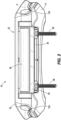
- Figs. 1 and 2 illustrate a toilet seat assembly 10 that is mountable to a toilet bowl (not shown).
- the toilet seat assembly 10 includes a toilet cover lid 14, a toilet seat 18, and a toilet seat hinge 22.
- the hinge 22 pivotally couples the cover 14 and the seat 18 to the toilet bowl about a pivot axis A.
- the hinge 22 is a platform-style hinge and is selectively fixed to the toilet bowl via two fasteners 38 that extend through the toilet bowl.
- the hinge 22 can include two separate portions each selectively fixed to the toilet bowl by one fastener 38 or one mounting post (e.g., such a construction is disclosed within U.S. Patent No. 9,986,878 . With continued reference to Figs.
- the illustrated toilet seat hinge 22 includes a post 26, a quick-disconnect cap 30 (e.g., a locking member) pivotally coupled to the post 26, and a base 34 selectively coupled to the post 26 and the cap 30 as discussed in more detail below.
- a quick-disconnect cap 30 e.g., a locking member
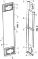
- the illustrated post 26 includes an upright portion 40 and a frame 42 extending from the upright portion 40.
- the upright portion 40 is generally perpendicular to the frame 42 (e.g., the upright portion 40 extends away from an upper surface of the toilet bowl) and extends in a longitudinal direction that is parallel to the pivot axis A.
- the upright portion 40 includes sleeves 44 on each end of the post 26, and each of the sleeves 44 includes an opening 46.
- the two openings 46 are concentric to define the pivot axis A.
- slow close dampers 48 are received within the sleeves 44.
- the slow close dampers 48 are coupled to the toilet cover lid 14 and the toilet seat 18 to enable movement of the lid 14 and the seat 18 relative to the post 26.
- the sleeves 44 may receive other members (e.g., fixed pins, etc.) to support the lid 14 and the seat 18 relative to the post 26.
- the upright portion 40 is substantially hollow to define a cavity 50 in which the sleeves 44 are arranged.
- the upright portion 40 can be a substantially solid member.
- the post 26 further includes supports 58, 60, 62 (e.g., legs) disposed within the cavity 50.
- the first and second legs 58, 60 support the sleeves 44 relative to the toilet bowl, and the third leg 62 supports a mid-section of the upright portion 40 relative to the toilet bowl as discussed in more detail below.
- the frame 42 includes side members 66 which project from each end of the upright portion 40, a cross member 74 connecting the side members 66, and a central member 78 connecting a portion (e.g., a center portion) of the cross member 74 to a portion (e.g., a center portion) of the upright portion 40.
- the side members 66 and the cross member 74 define an opening of a slot 64 that extends from a rear end of the frame 42 to the legs 58, 60, 62 of the upright portion 40 in a direction perpendicular to the pivot axis A.
- each side member 66 includes a rail 70 extending toward each other into the slot 64 (e.g., extending in a direction parallel to the pivot axis A).
- the cross member 74, the side members 66, the central member 78, and a rear portion of the upright portion 40 define two openings 82 to provide top access to the slot 64.
- the openings 82 can be omitted such that the central member 78 extends between the side members 66 forming a continuous upper wall of the slot 64.
- the illustrated cap 30 includes a cover 86 and pivot portions 90 (e.g., arms) extending from the cover 86.
- the pivot portions 90 are pivotally coupled to the upright portion 40 (e.g., via the soft close dampers 48), enabling the cap 30 to be pivotally coupled to the post 26 about the pivot axis A.
- Each pivot portion 90 includes an opening 94 that aligns with an opening 46 of the upright portion 40.
- the cover 86 includes a grip portion 96 (e.g., an actuator) that protrudes from a top surface of the cover 86 and is engageable by a user to pivot the cap 30 about the pivot axis A.
- the grip portion 96 is a lip.
- the grip portion 96 may include other suitable structures that may be engaged by a user, such as one or more vertical or side projections, one or more recesses, and the like.
- the cover 86 further includes a wall 98 extending around three sides of the cover 86.
- the wall 98 can extend from one side of the cover 86 (e.g., underneath the grip portion 96).
- the illustrated wall 98 includes a recess 100 formed in an interior surface of the wall 98.
- the cover 86 further includes a bottom surface 101 including protrusions 102 spaced from the interior surface of the wall 98 such that a gap 103 is positioned between each protrusion 102 and the wall 98 including the recess 100.
- Each illustrated protrusion 102 has an L-shaped cross-section at an end adjacent the bottom surface 101 and a triangular cross-section at a free end of the protrusion 102.
- the cover 86 includes two pairs of protrusions 102. In other embodiments, the cover 86 can include fewer or more than two pairs of protrusions 102 (e.g., each pair can form a single protrusion, a single protrusion can extend in a direction parallel to the pivot axis A, etc.).
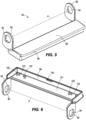
- the base 34 includes a top side 104 and a bottom side 106 opposite the top side 104.
- the top side 104 and the bottom side 106 each terminate at a first end 108 and a second end 110 opposite the first end 108.
- a rear edge 112 extends between the top side 104 and the bottom side 106 and between the first end 108 and the second end 110.
- the base 34 is a unitary base that presents itself as one piece.
- the base 34 may be made of a single piece of plastic.
- the base 34 may be made of multiple pieces that are permanently secured together by welding, gluing, fastening, molding, and the like.
- the bottom side 106 of the base 34 abuts the toilet bowl when the base 34 is affixed to the toilet bowl by the fasteners 38.
- two recesses 116 are formed on the top side 104 of the base 34 adjacent the first end 108 and the second end 110, respectively.
- the base 34 also includes elongated through holes 114, each extending through one of the recesses 116. Each through hole 114 is sized to receive a shaft and a resilient bushing of a fastener 38, and each recess 116 is sized to receive a head of a fastener 38.
- the recesses 116 include a bottom contoured surface (e.g., jagged surface) that engages with a lower contoured surface (e.g., jagged surface) of the heads of the fasteners 38 to hold a position of the fasteners 38 within the elongated through holes 114.
- the bottom side 106 includes two slots 118 with one of the slots 118 adjacent the first end 108 and another one of the slots 118 adjacent the second end 110.
- the base 34 further includes a projection 122 extending from the rear edge 112.
- the post 26, the cap 30, the toilet seat 18, and the toilet lid 14 are aligned along the pivot axis A to be coupled together by the slow close dampers 48.
- the openings 94 of the cap 30 are aligned with the openings 46 of the post 26.
- the toilet cover lid 14 and the toilet seat 18 are then aligned with the openings 46, 94.
- the slow close dampers 48 are inserted into the sleeves 44 of the post 26 through pivot rings of the toilet seat 18, pivot rings of the toilet lid 14, and the pivot portions 90 of the cap 30.
- inserts 124 ( Figs. 1 and 2 ) are then inserted into sides of the lid 14 to engage the pivot rings of the lid 14 and the pivot rings of the seat 18.
- the inserts 124 fix the lid 14 and the seat 18 to outboard portions of the slow close dampers 48, whereas inboard portions of the slow close dampers 48 are fixed within the sleeves 44. Accordingly, the slow close dampers 48 control movement of the lid 14 and/or the seat 18 relative to the post 26 about the pivot axis A.
- the cap 30 is freely pivotable about the pivot axis A.
- Figs. 9-11 illustrate assembly of the toilet seat assembly 10 to the toilet bowl.
- the disclosure of assembling the toilet seat assembly 10 to the toilet bowl is discussed in specific steps below, not all of the steps need to be performed. In addition, the disclosed steps do not need to be performed in the disclosed order. Assembly of the toilet seat assembly 10 to the toilet bowl can also include additional or alternative steps.
- the lid 14, the seat 18, the cap 30, and the post 26 are separated from the base 34, and the base 34 is fixed to the toilet bowl by the fasteners 38.
- the fasteners 38 are inserted into the through holes 114 ( Figs. 7 and 8 ) so that fastening nuts are tightened onto the fasteners 38 to clamp the base 34 to the toilet bowl.
- the base 34 can be adjusted relative to the toilet bowl as the recesses 116 provide clearance for the heads of the fasteners 38 to move within the recesses 116 (e.g., to adjust the base 34 in a forward direction or a rearward direction).
- the heads of the fasteners 38 rest within the recesses 116 to be substantially flush with the top side 104 of the base 34.
- the illustrated heads of the fasteners 38 may not include any type of tightening mechanism (e.g., a slot that receives a screwdriver, a hexagonal protrusion to be engaged by a drive socket, etc.) such that the fastening nuts threaded onto the fasteners 38 are the tightening mechanisms to fix the base 34 to the toilet bowl.
- the assembly of the lid 14, the seat 18, the post 26, and the cap 30 is then slid onto the base 34.
- the post 26 moves in a first direction D1 (parallel to the upper surface of the toilet bowl that supports the base 34) over the base 34 such that the slot 64 of the post 26 receives the base 34.
- the rails 70 of the post 26 and the slots 118 of the base 34 are in engagement to inhibit the post 26 from moving upwardly away from the upper surface of the toilet bowl.
- the post 26 is slid onto the base 34 until the base 34 contacts the legs 58, 60, 62 (e.g., engagement between the legs 58, 60, 62 and the base 34 limits an insertion depth of the base 34 within the slot 64).
- the base 34 and the post 26 can include detent members to releasably hold the post 26 on the base 34 as shown in Fig. 10 .
- the cap 30 is in an unlocked position U that provides access to the fasteners 38 through the openings 82 of the post 26.
- the cap 30 in an installed and locked position P3, the cap 30 is pivoted down about the pivot axis A toward the base 34 into a locked position L to secure the assembly of the toilet lid 14, the toilet seat 18, the cap 30, and the post 26 onto the base 34.
- the wall 98 of the cap 30 covers the slot 64 of the post 26 such that the post 26 is inhibited from moving in a second direction D2 opposite the first direction D1 to separate from the base 34.
- the fasteners 38 are additionally covered by the cap 30 and are inaccessible in the locked position L of the cap 30.
- the projection 122 of the base 34 is received within the recess 100 of the cap 30 to releasably hold the cap 30 in the locked position L.
- the projection 122 and the recess 100 together form a force-fit connection between the base 34 and the cap 30.
- the projection 122 engages the recess 100 so that a sufficient force on the cap 30 is required to disengage the cap 30 from the base 34 and move the cap 30 into the unlocked position U.
- the sufficient force may be obtained by a user pushing up on the grip portion 96 of the cap 30.
- the cap 30 may include the projection 122
- the base 34 may include the recess 100.
- other types of mechanisms can releasably hold the cap 30 to the base 34, such as a magnet or a friction fit-type interface.
- the cross member 74 of the post 26 is received within the gap 103 of the cap 30.
- the cross member 74 engages the protrusions 102 and the wall 98 to assist the engagement between the projection 122 and the recess 100 in holding the cap 30 in the locked position L.
- the legs 58, 60, 62 of the post 26 contact the toilet bowl to support the hinge 22 on the toilet bowl. Accordingly, during use of the toilet seat assembly 10, a user sits on the toilet seat 18 when in the in-use position and at least the legs 58, 60, 62 distribute the weight of the user through the post 26 and to the toilet bowl.
- the illustrated slow close dampers 48 inhibit the lid 14 and/or the seat 18 from slamming down onto the toilet bowl from a raised position.
- the user may provide the sufficient force on the grip portion 96 of the cap 30 to move the cap 30 into the unlocked position U ( Fig. 10 ). Thereafter, the assembly of the lid 14, the seat 18, the post 26, and the cap 30 can slide off the base 34 in the second direction D2 to remove the lid 14 and the seat 18 from the toilet bowl.
Landscapes
- Health & Medical Sciences (AREA)
- Public Health (AREA)
- Toilet Supplies (AREA)
Claims (9)
- Toilettensitzscharnier (22), das zum Koppeln eines Toilettensitzes (18) an eine Toilettenschüssel ausgestaltet ist, wobei das Toilettensitzscharnier (22) Folgendes umfasst:eine Basis (34), die zum Koppeln an eine obere Fläche der Toilettenschüssel ausgestaltet ist,einen Pfosten (26), der eine Drehachse (A) definiert, um die sich der Toilettensitz (18) drehen kann, wobei der Pfosten (26) in eine parallel zu der oberen Fläche der Toilettenschüssel verlaufende Richtung auf die Basis (34) schiebbar ist, um den Pfosten (26) an die Basis (34) zu koppeln, und gekennzeichnet durcheine Kappe (30), die schwenkbar an den Pfosten (26) gekoppelt ist, wobei die Kappe (30) um die Drehachse (A) schwenkbar ist, um den Pfosten (26) an der Basis (34) zu befestigen.
- Toilettensitzscharnier (22) nach Anspruch 1, wobei die Kappe (30) zwischen einer entriegelten Position, in der der Pfosten (26) auf die und von der Basis (34) weg schiebbar ist, und einer verriegelten Position schwenkbar ist, in der die Kappe (30) ein Schieben des Pfostens (26) bezüglich der Basis (34) verhindert.
- Toilettensitzscharnier (22) nach Anspruch 2, wobei die Kappe (30) in der verriegelten Position die Basis (34) in Eingriff nimmt.
- Toilettensitzscharnier (22) nach Anspruch 3, wobei die Kappe (30) oder die Basis (34) eine Aussparung (100) aufweist, wobei die jeweils andere der Kappe (30) oder der Basis (34) einen Vorsprung (122) aufweist und wobei der Vorsprung (122) die Aussparung (100) in Eingriff nimmt, wenn die Kappe (30) in der verriegelten Position ist, um die Kappe (30) in der verriegelten Position zu befestigen.
- Toilettensitzscharnier (22) nach einem der vorhergehenden Ansprüche, wobei der Pfosten (26) in eine Richtung, die senkrecht zu der Drehachse (A) verläuft, auf die Basis schiebbar ist.
- Toilettensitzscharnier (22) nach einem der vorhergehenden Ansprüche, wobei die Basis (34) eine einteilige Basis ist, die ein erstes Durchgangsloch (114), das zur Aufnahme eines ersten Befestigungselements (38) ausgestaltet ist, und ein zweites Durchgangsloch (114), das zur Aufnahme eines zweiten Befestigungselements (38) ausgestaltet ist, definiert.
- Toilettensitzscharnier (22) nach Anspruch 6, wobei die Kappe (30) sowohl das erste Durchgangsloch (114) als auch das zweite Durchgangsloch (114) abdeckt.
- Toilettensitzscharnier (22) nach einem der vorhergehenden Ansprüche, wobei die Kappe (30) einen Griffabschnitt (96) aufweist, der von einem Benutzer in Eingriff genommen werden kann, um die Kappe (30) bezüglich der Basis (34) zu schwenken.
- Verfahren zum Koppeln eines plattformartigen Toilettensitzscharniers (22) an eine Toilettenschüssel, wobei das plattformartige Toilettensitzscharnier (22) eine einteilige Basis (34), einen Pfosten (26) und eine an den Pfosten (26) gekoppelte Kappe (30) aufweist, wobei das Verfahren Folgendes umfasst:Positionieren der einteiligen Basis (34) auf eine obere Fläche der Toilettenschüssel, wobei die einteilige Basis (34) ein erstes Ende (108) und ein zweites Ende (110) gegenüber dem ersten Ende aufweist, wobei die einteilige Basis (34) ein erstes Durchgangsloch (114) nahe dem ersten Ende (108) und ein zweites Durchgangsloch (114) nahe dem zweiten Ende (110) definiert,Einführen eines ersten Befestigungselements (38) durch das erste Durchgangsloch (114), um die einteilige Basis (34) an die Toilettenschüssel zu koppeln,Einführen eines zweiten Befestigungselements (38) durch das zweite Durchgangsloch (114), um die einteilige Basis (34) an die Toilettenschüssel zu koppeln,Schieben des Pfostens (26) in eine parallel zu der oberen Fläche der Toilettenschüssel verlaufende Richtung auf die einteilige Basis (34), wobei der Pfosten (26) eine Drehachse (A) definiert, um die ein Toilettensitz (18) schwenken kann,dadurch gekennzeichnet, dass das Verfahren ferner Folgendes umfasst:
Schwenken der Kappe (30) bezüglich des Pfostens (26) um die Drehachse (A), um den Pfosten (26) an der einteiligen Basis (34) zu befestigen.
Applications Claiming Priority (1)
| Application Number | Priority Date | Filing Date | Title |
|---|---|---|---|
| US202163153106P | 2021-02-24 | 2021-02-24 |
Publications (2)
| Publication Number | Publication Date |
|---|---|
| EP4049569A1 EP4049569A1 (de) | 2022-08-31 |
| EP4049569B1 true EP4049569B1 (de) | 2024-12-18 |
Family
ID=80448350
Family Applications (1)
| Application Number | Title | Priority Date | Filing Date |
|---|---|---|---|
| EP22158320.6A Active EP4049569B1 (de) | 2021-02-24 | 2022-02-23 | Toilettensitzscharnier |
Country Status (4)
| Country | Link |
|---|---|
| US (1) | US11800958B2 (de) |
| EP (1) | EP4049569B1 (de) |
| CN (1) | CN114947597A (de) |
| MX (1) | MX2022002289A (de) |
Families Citing this family (3)
| Publication number | Priority date | Publication date | Assignee | Title |
|---|---|---|---|---|
| US11064851B2 (en) | 2015-11-18 | 2021-07-20 | Robert T. Poleki | Cleaning toilet seats |
| US12419472B2 (en) | 2015-11-18 | 2025-09-23 | Fufuloo Products, Llc | Cleaning toilet seats |
| US12453447B2 (en) * | 2021-11-01 | 2025-10-28 | Bemis Manufacturing Company | Toilet seat assembly |
Family Cites Families (54)
| Publication number | Priority date | Publication date | Assignee | Title |
|---|---|---|---|---|
| CH590044A5 (de) | 1975-01-10 | 1977-07-29 | Owo Presswerk Ag | |
| US4729134A (en) | 1985-12-06 | 1988-03-08 | Kohler Co. | Toilet covering hinge assembly |
| US5193228A (en) | 1991-05-10 | 1993-03-16 | Matsushita Electric Works, Ltd. | Toilet covering hinge assembly with damping capability |
| US5933875A (en) | 1997-04-03 | 1999-08-10 | Bemis Manufacturing Company | Lift-off toilet seat hinge |
| US6070295A (en) | 1998-09-22 | 2000-06-06 | Bemis Manufacturing Company | Quick release toilet seat hinge with swivel |
| US6243884B1 (en) | 1999-08-18 | 2001-06-12 | Itt Manufacturing Enterprises, Inc. | Toilet seat assembly having an upright position lock |
| US6381762B1 (en) * | 2001-03-15 | 2002-05-07 | Scott A. Moser | Quick release toilet seat hinge assembly |
| US7389549B2 (en) | 2004-09-24 | 2008-06-24 | Kohler Co. | Quick release toilet seat hinge assembly |
| US7203975B2 (en) | 2004-09-24 | 2007-04-17 | Kohler Co. | Releasable toilet seat hinge assembly |
| US20060156458A1 (en) | 2005-01-18 | 2006-07-20 | Myers Douglas A | Family toilet seat and cover assembly having fluid damped slow-close hinges for all hinged components |
| JP4516465B2 (ja) * | 2005-03-29 | 2010-08-04 | アイシン精機株式会社 | 便座装置 |
| CA2552316A1 (en) | 2005-07-20 | 2007-01-20 | Clarifia | Toilet seat hinge |
| US20070250996A1 (en) | 2006-04-27 | 2007-11-01 | Feiyu Li | Hinge assembly for toilet seat |
| CN101534690B (zh) | 2006-10-13 | 2011-09-28 | 碧美斯制造公司 | 马桶座圈铰链和制造方法 |
| US7712157B2 (en) * | 2007-05-04 | 2010-05-11 | Kohler Co. | Releasable toilet seat assembly |
| US8205274B2 (en) | 2007-11-01 | 2012-06-26 | Wdi International, Inc. | Lift and clean toilet seat hinge |
| US9635987B2 (en) | 2008-02-22 | 2017-05-02 | Bemis Manufacturing Company | Hinge assembly for a toilet seat |
| CN201211152Y (zh) | 2008-07-09 | 2009-03-25 | 周裕佳 | 坐便器坐圈及盖板的快速拆装机构 |
| US8209789B2 (en) * | 2008-11-11 | 2012-07-03 | Ldr Industries Inc. | Quick-release structure of a toilet cover hinge |
| DE102008058580B4 (de) | 2008-11-23 | 2012-10-11 | Hamberger Industriewerke Gmbh | WC-Sitzgelenk |
| US8214932B2 (en) | 2009-02-11 | 2012-07-10 | Smart Lid, Llc | Automatic self-closing toilet seat assembly |
| US20100223718A1 (en) | 2010-04-13 | 2010-09-09 | Andersen Robert A | Automatic Toilet Seat Assembly Closing System |
| US8943618B2 (en) | 2010-07-13 | 2015-02-03 | Centoco Plastics Limited | Toilet seat hinge assembly |
| US8763168B2 (en) | 2011-01-05 | 2014-07-01 | Zhongshan Meitu Plastic Ind. Co., Ltd. | Hinge assembly for toilet seat |
| US9212478B2 (en) | 2011-05-20 | 2015-12-15 | Kohler Co. | Toilet installation system and method |
| WO2012162174A1 (en) | 2011-05-20 | 2012-11-29 | Kohler Co. | Toilet installation system and method |
| US9986878B2 (en) | 2011-09-15 | 2018-06-05 | Bemis Manufacturing Company | Toilet seat hinge |
| CN103180527B (zh) | 2011-10-21 | 2014-10-15 | 科勒公司 | 手动净身器 |
| US10655313B2 (en) | 2012-09-06 | 2020-05-19 | Kohler Co. | Grey water toilet |
| CN103806518B (zh) | 2012-11-02 | 2015-09-30 | 科勒公司 | 改进型非接触式冲洗系统和方法 |
| CN104627543B (zh) | 2013-11-11 | 2017-05-10 | 科勒公司 | 一次性湿巾分配器系统 |
| CN104161482B (zh) * | 2014-08-07 | 2017-09-26 | 温岭市美的工艺制品厂 | 一种用于安装马桶盖板的铰链组件 |
| CN114164904B (zh) | 2015-08-24 | 2024-06-18 | 科勒公司 | 具有传感、冲洗和通风功能件的马桶 |
| CN105297855B (zh) | 2015-09-16 | 2017-02-01 | 上海科勒电子科技有限公司 | 防逆流水箱及防逆流系统 |
| EP3248524B1 (de) | 2016-05-26 | 2020-09-09 | Kohler Mira Limited | Deckelinstallationszubehör und sitzanordnung |
| US10352031B2 (en) | 2016-09-22 | 2019-07-16 | Kohler Co. | Toilet with overflow protection |
| US10575685B2 (en) | 2016-11-01 | 2020-03-03 | Kohler Co. | Bathroom fixtures and components |
| US10337223B2 (en) | 2016-11-23 | 2019-07-02 | Kohler Co. | Shower door hinge assembly |
| US10194777B2 (en) | 2017-02-06 | 2019-02-05 | Kohler Co. | Toilet seat lighting apparatuses |
| US10414540B2 (en) | 2017-04-05 | 2019-09-17 | Kohler Co. | Toilet seat package |
| US11118338B2 (en) | 2017-05-22 | 2021-09-14 | Kohler Co. | Plumbing fixtures with insert-molded components |
| US10201258B1 (en) | 2017-08-10 | 2019-02-12 | Kohler Co. | Layered toilet seat |
| US11314215B2 (en) | 2017-09-15 | 2022-04-26 | Kohler Co. | Apparatus controlling bathroom appliance lighting based on user identity |
| US11093554B2 (en) | 2017-09-15 | 2021-08-17 | Kohler Co. | Feedback for water consuming appliance |
| US10448762B2 (en) | 2017-09-15 | 2019-10-22 | Kohler Co. | Mirror |
| US11099540B2 (en) | 2017-09-15 | 2021-08-24 | Kohler Co. | User identity in household appliances |
| US10887125B2 (en) | 2017-09-15 | 2021-01-05 | Kohler Co. | Bathroom speaker |
| US10738448B2 (en) | 2017-12-04 | 2020-08-11 | Kohler Co. | Toilet coupling |
| US10610069B2 (en) | 2018-01-06 | 2020-04-07 | Kohler Co. | Toilet seat and hinge |
| US11039719B2 (en) | 2018-04-11 | 2021-06-22 | Kohler Co. | Toilet |
| US10463209B1 (en) | 2018-04-17 | 2019-11-05 | Kohler Co. | Toilet seat hinge |
| CN112384114B (zh) | 2018-05-11 | 2022-10-04 | 科勒公司 | 马桶的脚架结构 |
| US11622067B2 (en) | 2018-05-31 | 2023-04-04 | Kohler Co. | Connected bathroom components |
| US10912431B2 (en) | 2018-07-10 | 2021-02-09 | Kohler Co. | Hinge assembly for toilet |
-
2022
- 2022-02-23 EP EP22158320.6A patent/EP4049569B1/de active Active
- 2022-02-23 MX MX2022002289A patent/MX2022002289A/es unknown
- 2022-02-23 CN CN202210167882.5A patent/CN114947597A/zh active Pending
- 2022-02-24 US US17/679,624 patent/US11800958B2/en active Active
Also Published As
| Publication number | Publication date |
|---|---|
| CN114947597A (zh) | 2022-08-30 |
| EP4049569A1 (de) | 2022-08-31 |
| US11800958B2 (en) | 2023-10-31 |
| US20220265099A1 (en) | 2022-08-25 |
| MX2022002289A (es) | 2022-08-25 |
Similar Documents
| Publication | Publication Date | Title |
|---|---|---|
| EP4049569B1 (de) | Toilettensitzscharnier | |
| CA2848986C (en) | Assist handle assembly for beds | |
| EP3155946B1 (de) | Scharnieranordnung für toilettensitz | |
| RU2381002C2 (ru) | Узел съемного сиденья для унитаза | |
| CN101189143A (zh) | 具有整体调整装置的座椅安装装置 | |
| US8209789B2 (en) | Quick-release structure of a toilet cover hinge | |
| EP2640246B1 (de) | Scharnieranordnung für toilettensitz | |
| AU2005289924A1 (en) | Releasable toilet seat hinge assembly | |
| AU2005289856B2 (en) | Quick release toilet seat hinge assembly | |
| CA2636935A1 (en) | Toilet seat elevator assembly | |
| KR20040024207A (ko) | 글로브 박스의 댐퍼 시스템 | |
| JP2679628B2 (ja) | 天板と脚要素の連結構造 | |
| JPH064989B2 (ja) | ヒンジ | |
| JPH0870955A (ja) | 椅子の背もたれクッション取付構造 | |
| JP3057306B2 (ja) | 連動折り戸用の走行体とヒンジの着脱装置 | |
| JP3134065B2 (ja) | 引戸錠用係止装置 | |
| EP1155651B1 (de) | Befestigungsanordnung für ein WC-Brillenpufferelement | |
| US20250311897A1 (en) | Raised toilet seat with removable handrails | |
| JP2001158244A (ja) | リッドホルダ構造 | |
| JP5347140B2 (ja) | 椅子 | |
| CA2726530A1 (en) | Quick-release structure of a toilet cover hinge | |
| KR20040080082A (ko) | 가구용 힌지조립체 | |
| JP2014079530A (ja) | フラップ天板付家具 | |
| JPH0960361A (ja) | 鍵装置の受け具 | |
| GB2210913A (en) | W.C. seat assembly |
Legal Events
| Date | Code | Title | Description |
|---|---|---|---|
| PUAI | Public reference made under article 153(3) epc to a published international application that has entered the european phase |
Free format text: ORIGINAL CODE: 0009012 |
|
| STAA | Information on the status of an ep patent application or granted ep patent |
Free format text: STATUS: THE APPLICATION HAS BEEN PUBLISHED |
|
| AK | Designated contracting states |
Kind code of ref document: A1 Designated state(s): AL AT BE BG CH CY CZ DE DK EE ES FI FR GB GR HR HU IE IS IT LI LT LU LV MC MK MT NL NO PL PT RO RS SE SI SK SM TR |
|
| STAA | Information on the status of an ep patent application or granted ep patent |
Free format text: STATUS: REQUEST FOR EXAMINATION WAS MADE |
|
| 17P | Request for examination filed |
Effective date: 20230110 |
|
| RBV | Designated contracting states (corrected) |
Designated state(s): AL AT BE BG CH CY CZ DE DK EE ES FI FR GB GR HR HU IE IS IT LI LT LU LV MC MK MT NL NO PL PT RO RS SE SI SK SM TR |
|
| GRAP | Despatch of communication of intention to grant a patent |
Free format text: ORIGINAL CODE: EPIDOSNIGR1 |
|
| STAA | Information on the status of an ep patent application or granted ep patent |
Free format text: STATUS: GRANT OF PATENT IS INTENDED |
|
| INTG | Intention to grant announced |
Effective date: 20240712 |
|
| GRAS | Grant fee paid |
Free format text: ORIGINAL CODE: EPIDOSNIGR3 |
|
| GRAA | (expected) grant |
Free format text: ORIGINAL CODE: 0009210 |
|
| STAA | Information on the status of an ep patent application or granted ep patent |
Free format text: STATUS: THE PATENT HAS BEEN GRANTED |
|
| AK | Designated contracting states |
Kind code of ref document: B1 Designated state(s): AL AT BE BG CH CY CZ DE DK EE ES FI FR GB GR HR HU IE IS IT LI LT LU LV MC MK MT NL NO PL PT RO RS SE SI SK SM TR |
|
| REG | Reference to a national code |
Ref country code: CH Ref legal event code: EP |
|
| REG | Reference to a national code |
Ref country code: DE Ref legal event code: R096 Ref document number: 602022008709 Country of ref document: DE |
|
| REG | Reference to a national code |
Ref country code: IE Ref legal event code: FG4D |
|
| REG | Reference to a national code |
Ref country code: LT Ref legal event code: MG9D |
|
| PG25 | Lapsed in a contracting state [announced via postgrant information from national office to epo] |
Ref country code: HR Free format text: LAPSE BECAUSE OF FAILURE TO SUBMIT A TRANSLATION OF THE DESCRIPTION OR TO PAY THE FEE WITHIN THE PRESCRIBED TIME-LIMIT Effective date: 20241218 |
|
| PGFP | Annual fee paid to national office [announced via postgrant information from national office to epo] |
Ref country code: DE Payment date: 20250218 Year of fee payment: 4 |
|
| PG25 | Lapsed in a contracting state [announced via postgrant information from national office to epo] |
Ref country code: FI Free format text: LAPSE BECAUSE OF FAILURE TO SUBMIT A TRANSLATION OF THE DESCRIPTION OR TO PAY THE FEE WITHIN THE PRESCRIBED TIME-LIMIT Effective date: 20241218 |
|
| PG25 | Lapsed in a contracting state [announced via postgrant information from national office to epo] |
Ref country code: BG Free format text: LAPSE BECAUSE OF FAILURE TO SUBMIT A TRANSLATION OF THE DESCRIPTION OR TO PAY THE FEE WITHIN THE PRESCRIBED TIME-LIMIT Effective date: 20241218 |
|
| PG25 | Lapsed in a contracting state [announced via postgrant information from national office to epo] |
Ref country code: NO Free format text: LAPSE BECAUSE OF FAILURE TO SUBMIT A TRANSLATION OF THE DESCRIPTION OR TO PAY THE FEE WITHIN THE PRESCRIBED TIME-LIMIT Effective date: 20250318 |
|
| REG | Reference to a national code |
Ref country code: NL Ref legal event code: MP Effective date: 20241218 |
|
| PG25 | Lapsed in a contracting state [announced via postgrant information from national office to epo] |
Ref country code: LV Free format text: LAPSE BECAUSE OF FAILURE TO SUBMIT A TRANSLATION OF THE DESCRIPTION OR TO PAY THE FEE WITHIN THE PRESCRIBED TIME-LIMIT Effective date: 20241218 Ref country code: GR Free format text: LAPSE BECAUSE OF FAILURE TO SUBMIT A TRANSLATION OF THE DESCRIPTION OR TO PAY THE FEE WITHIN THE PRESCRIBED TIME-LIMIT Effective date: 20250319 |
|
| PGFP | Annual fee paid to national office [announced via postgrant information from national office to epo] |
Ref country code: FR Payment date: 20250224 Year of fee payment: 4 |
|
| PG25 | Lapsed in a contracting state [announced via postgrant information from national office to epo] |
Ref country code: RS Free format text: LAPSE BECAUSE OF FAILURE TO SUBMIT A TRANSLATION OF THE DESCRIPTION OR TO PAY THE FEE WITHIN THE PRESCRIBED TIME-LIMIT Effective date: 20250318 |
|
| PG25 | Lapsed in a contracting state [announced via postgrant information from national office to epo] |
Ref country code: NL Free format text: LAPSE BECAUSE OF FAILURE TO SUBMIT A TRANSLATION OF THE DESCRIPTION OR TO PAY THE FEE WITHIN THE PRESCRIBED TIME-LIMIT Effective date: 20241218 |
|
| REG | Reference to a national code |
Ref country code: AT Ref legal event code: MK05 Ref document number: 1751505 Country of ref document: AT Kind code of ref document: T Effective date: 20241218 |
|
| PG25 | Lapsed in a contracting state [announced via postgrant information from national office to epo] |
Ref country code: SM Free format text: LAPSE BECAUSE OF FAILURE TO SUBMIT A TRANSLATION OF THE DESCRIPTION OR TO PAY THE FEE WITHIN THE PRESCRIBED TIME-LIMIT Effective date: 20241218 |
|
| PG25 | Lapsed in a contracting state [announced via postgrant information from national office to epo] |
Ref country code: PL Free format text: LAPSE BECAUSE OF FAILURE TO SUBMIT A TRANSLATION OF THE DESCRIPTION OR TO PAY THE FEE WITHIN THE PRESCRIBED TIME-LIMIT Effective date: 20241218 |
|
| PG25 | Lapsed in a contracting state [announced via postgrant information from national office to epo] |
Ref country code: ES Free format text: LAPSE BECAUSE OF FAILURE TO SUBMIT A TRANSLATION OF THE DESCRIPTION OR TO PAY THE FEE WITHIN THE PRESCRIBED TIME-LIMIT Effective date: 20241218 |
|
| PG25 | Lapsed in a contracting state [announced via postgrant information from national office to epo] |
Ref country code: IS Free format text: LAPSE BECAUSE OF FAILURE TO SUBMIT A TRANSLATION OF THE DESCRIPTION OR TO PAY THE FEE WITHIN THE PRESCRIBED TIME-LIMIT Effective date: 20250418 |
|
| PG25 | Lapsed in a contracting state [announced via postgrant information from national office to epo] |
Ref country code: PT Free format text: LAPSE BECAUSE OF FAILURE TO SUBMIT A TRANSLATION OF THE DESCRIPTION OR TO PAY THE FEE WITHIN THE PRESCRIBED TIME-LIMIT Effective date: 20250421 |
|
| PG25 | Lapsed in a contracting state [announced via postgrant information from national office to epo] |
Ref country code: EE Free format text: LAPSE BECAUSE OF FAILURE TO SUBMIT A TRANSLATION OF THE DESCRIPTION OR TO PAY THE FEE WITHIN THE PRESCRIBED TIME-LIMIT Effective date: 20241218 |
|
| PG25 | Lapsed in a contracting state [announced via postgrant information from national office to epo] |
Ref country code: AT Free format text: LAPSE BECAUSE OF FAILURE TO SUBMIT A TRANSLATION OF THE DESCRIPTION OR TO PAY THE FEE WITHIN THE PRESCRIBED TIME-LIMIT Effective date: 20241218 Ref country code: RO Free format text: LAPSE BECAUSE OF FAILURE TO SUBMIT A TRANSLATION OF THE DESCRIPTION OR TO PAY THE FEE WITHIN THE PRESCRIBED TIME-LIMIT Effective date: 20241218 |
|
| PG25 | Lapsed in a contracting state [announced via postgrant information from national office to epo] |
Ref country code: SK Free format text: LAPSE BECAUSE OF FAILURE TO SUBMIT A TRANSLATION OF THE DESCRIPTION OR TO PAY THE FEE WITHIN THE PRESCRIBED TIME-LIMIT Effective date: 20241218 |
|
| PG25 | Lapsed in a contracting state [announced via postgrant information from national office to epo] |
Ref country code: CZ Free format text: LAPSE BECAUSE OF FAILURE TO SUBMIT A TRANSLATION OF THE DESCRIPTION OR TO PAY THE FEE WITHIN THE PRESCRIBED TIME-LIMIT Effective date: 20241218 |
|
| PG25 | Lapsed in a contracting state [announced via postgrant information from national office to epo] |
Ref country code: IT Free format text: LAPSE BECAUSE OF FAILURE TO SUBMIT A TRANSLATION OF THE DESCRIPTION OR TO PAY THE FEE WITHIN THE PRESCRIBED TIME-LIMIT Effective date: 20241218 |
|
| PG25 | Lapsed in a contracting state [announced via postgrant information from national office to epo] |
Ref country code: SE Free format text: LAPSE BECAUSE OF FAILURE TO SUBMIT A TRANSLATION OF THE DESCRIPTION OR TO PAY THE FEE WITHIN THE PRESCRIBED TIME-LIMIT Effective date: 20241218 |
|
| PG25 | Lapsed in a contracting state [announced via postgrant information from national office to epo] |
Ref country code: MC Free format text: LAPSE BECAUSE OF FAILURE TO SUBMIT A TRANSLATION OF THE DESCRIPTION OR TO PAY THE FEE WITHIN THE PRESCRIBED TIME-LIMIT Effective date: 20241218 |
|
| REG | Reference to a national code |
Ref country code: DE Ref legal event code: R097 Ref document number: 602022008709 Country of ref document: DE |
|
| REG | Reference to a national code |
Ref country code: CH Ref legal event code: PL |
|
| PG25 | Lapsed in a contracting state [announced via postgrant information from national office to epo] |
Ref country code: DK Free format text: LAPSE BECAUSE OF FAILURE TO SUBMIT A TRANSLATION OF THE DESCRIPTION OR TO PAY THE FEE WITHIN THE PRESCRIBED TIME-LIMIT Effective date: 20241218 |
|
| PG25 | Lapsed in a contracting state [announced via postgrant information from national office to epo] |
Ref country code: LU Free format text: LAPSE BECAUSE OF NON-PAYMENT OF DUE FEES Effective date: 20250223 |
|
| PG25 | Lapsed in a contracting state [announced via postgrant information from national office to epo] |
Ref country code: CH Free format text: LAPSE BECAUSE OF NON-PAYMENT OF DUE FEES Effective date: 20250228 |
|
| PLBE | No opposition filed within time limit |
Free format text: ORIGINAL CODE: 0009261 |
|
| STAA | Information on the status of an ep patent application or granted ep patent |
Free format text: STATUS: NO OPPOSITION FILED WITHIN TIME LIMIT |
|
| 26N | No opposition filed |
Effective date: 20250919 |