EP4048873B1 - Steuerungsschemata zur wärmeverwaltung von energieerzeugungssystemen und verfahren - Google Patents
Steuerungsschemata zur wärmeverwaltung von energieerzeugungssystemen und verfahren Download PDFInfo
- Publication number
- EP4048873B1 EP4048873B1 EP20800335.0A EP20800335A EP4048873B1 EP 4048873 B1 EP4048873 B1 EP 4048873B1 EP 20800335 A EP20800335 A EP 20800335A EP 4048873 B1 EP4048873 B1 EP 4048873B1
- Authority
- EP
- European Patent Office
- Prior art keywords
- heu
- stream
- turbine
- exhaust stream
- temperature
- Prior art date
- Legal status (The legal status is an assumption and is not a legal conclusion. Google has not performed a legal analysis and makes no representation as to the accuracy of the status listed.)
- Active
Links
Images

Classifications
-
- F—MECHANICAL ENGINEERING; LIGHTING; HEATING; WEAPONS; BLASTING
- F01—MACHINES OR ENGINES IN GENERAL; ENGINE PLANTS IN GENERAL; STEAM ENGINES
- F01K—STEAM ENGINE PLANTS; STEAM ACCUMULATORS; ENGINE PLANTS NOT OTHERWISE PROVIDED FOR; ENGINES USING SPECIAL WORKING FLUIDS OR CYCLES
- F01K25/00—Plants or engines characterised by use of special working fluids, not otherwise provided for; Plants operating in closed cycles and not otherwise provided for
- F01K25/08—Plants or engines characterised by use of special working fluids, not otherwise provided for; Plants operating in closed cycles and not otherwise provided for using special vapours
- F01K25/10—Plants or engines characterised by use of special working fluids, not otherwise provided for; Plants operating in closed cycles and not otherwise provided for using special vapours the vapours being cold, e.g. ammonia, carbon dioxide, ether
- F01K25/103—Carbon dioxide
-
- B—PERFORMING OPERATIONS; TRANSPORTING
- B01—PHYSICAL OR CHEMICAL PROCESSES OR APPARATUS IN GENERAL
- B01D—SEPARATION
- B01D53/00—Separation of gases or vapours; Recovering vapours of volatile solvents from gases; Chemical or biological purification of waste gases, e.g. engine exhaust gases, smoke, fumes, flue gases, aerosols
- B01D53/34—Chemical or biological purification of waste gases
- B01D53/46—Removing components of defined structure
- B01D53/54—Nitrogen compounds
- B01D53/58—Ammonia
-
- B—PERFORMING OPERATIONS; TRANSPORTING
- B01—PHYSICAL OR CHEMICAL PROCESSES OR APPARATUS IN GENERAL
- B01D—SEPARATION
- B01D53/00—Separation of gases or vapours; Recovering vapours of volatile solvents from gases; Chemical or biological purification of waste gases, e.g. engine exhaust gases, smoke, fumes, flue gases, aerosols
- B01D53/34—Chemical or biological purification of waste gases
- B01D53/92—Chemical or biological purification of waste gases of engine exhaust gases
- B01D53/94—Chemical or biological purification of waste gases of engine exhaust gases by catalytic processes
- B01D53/9445—Simultaneously removing carbon monoxide, hydrocarbons or nitrogen oxides making use of three-way catalysts [TWC] or four-way-catalysts [FWC]
-
- F—MECHANICAL ENGINEERING; LIGHTING; HEATING; WEAPONS; BLASTING
- F02—COMBUSTION ENGINES; HOT-GAS OR COMBUSTION-PRODUCT ENGINE PLANTS
- F02C—GAS-TURBINE PLANTS; AIR INTAKES FOR JET-PROPULSION PLANTS; CONTROLLING FUEL SUPPLY IN AIR-BREATHING JET-PROPULSION PLANTS
- F02C3/00—Gas-turbine plants characterised by the use of combustion products as the working fluid
- F02C3/34—Gas-turbine plants characterised by the use of combustion products as the working fluid with recycling of part of the working fluid, i.e. semi-closed cycles with combustion products in the closed part of the cycle
-
- F—MECHANICAL ENGINEERING; LIGHTING; HEATING; WEAPONS; BLASTING
- F02—COMBUSTION ENGINES; HOT-GAS OR COMBUSTION-PRODUCT ENGINE PLANTS
- F02C—GAS-TURBINE PLANTS; AIR INTAKES FOR JET-PROPULSION PLANTS; CONTROLLING FUEL SUPPLY IN AIR-BREATHING JET-PROPULSION PLANTS
- F02C6/00—Plural gas-turbine plants; Combinations of gas-turbine plants with other apparatus; Adaptations of gas-turbine plants for special use
- F02C6/18—Plural gas-turbine plants; Combinations of gas-turbine plants with other apparatus; Adaptations of gas-turbine plants for special use using the waste heat of gas-turbine plants outside the plants themselves, e.g. gas-turbine power heat plants
-
- F—MECHANICAL ENGINEERING; LIGHTING; HEATING; WEAPONS; BLASTING
- F05—INDEXING SCHEMES RELATING TO ENGINES OR PUMPS IN VARIOUS SUBCLASSES OF CLASSES F01-F04
- F05D—INDEXING SCHEME FOR ASPECTS RELATING TO NON-POSITIVE-DISPLACEMENT MACHINES OR ENGINES, GAS-TURBINES OR JET-PROPULSION PLANTS
- F05D2210/00—Working fluids
- F05D2210/10—Kind or type
- F05D2210/12—Kind or type gaseous, i.e. compressible
-
- Y—GENERAL TAGGING OF NEW TECHNOLOGICAL DEVELOPMENTS; GENERAL TAGGING OF CROSS-SECTIONAL TECHNOLOGIES SPANNING OVER SEVERAL SECTIONS OF THE IPC; TECHNICAL SUBJECTS COVERED BY FORMER USPC CROSS-REFERENCE ART COLLECTIONS [XRACs] AND DIGESTS
- Y02—TECHNOLOGIES OR APPLICATIONS FOR MITIGATION OR ADAPTATION AGAINST CLIMATE CHANGE
- Y02E—REDUCTION OF GREENHOUSE GAS [GHG] EMISSIONS, RELATED TO ENERGY GENERATION, TRANSMISSION OR DISTRIBUTION
- Y02E20/00—Combustion technologies with mitigation potential
- Y02E20/14—Combined heat and power generation [CHP]
Definitions
- Provision of clean CO 2 for uses such as noted above typically includes separation of the CO 2 from an industrial gas mixture, which mixture often contains further compounds, such as CO, H 2 , sulfur, and the like. This, of course, requires a series of purification processes.
- the purification requirements as well as the need for providing the CO 2 at the desired pressure and/or temperature can entail procuring dedicated compression, cleanup, and heating equipment that leads to high capital costs and large energy consumptions.
- power production processes are typically configured for utilization and production of significant amounts of thermal energy.
- This thermal energy may be utilized directly in power production or may be available for further uses.
- there is a need for means for controlling power production processes such that various product flows, such as carbon dioxide and modes of thermal transfer, may be efficiently obtained and/or exported for a further use.
- the present disclosure thus provides to systems and methods whereby CO 2 arising from a power production cycle utilizing CO 2 as a working fluid can be taken as an end product and fed directly into a further downstream use of the material.
- the systems and methods of the present disclosure can allow for the export of CO 2 as a chemical feedstock and/or heat transfer fluid at various temperatures and pressures for use in downstream endothermic industrial processes.
- the presently disclosed systems and methods are beneficial in that low-grade heat can be provided to an external process. This may be accomplished in an example embodiment by using combustion-derived CO 2 effectively as a heat carrier.
- the present disclosure provides for management of plant turndown (i.e. turbine stability and operability) through the export of said low-grade heat along with changes to the flow rate through the hot gas compressor ("HGC") of the power production system from which the CO 2 is derived.
- HGC hot gas compressor
- the maximum temperature can be limited by the total heat quality and quantity that can be taken from the recuperative heat exchanger train utilized in the power production cycle before the hot gas compressor can no longer supplement the losses (i.e. maintain heat exchanger profile).
- the systems and methods of the present disclosure can provide distinct advantages over other possible industrial sources of CO 2 , such as systems wherein CO 2 compression heat is recovered in order to help generate steam that is used to strip CO 2 from recovery columns.
- the heat recovery process is an add-on independent of direct power generation activities and thus cannot provide many of the advantages of the presently disclosed systems and methods.
- known systems and methods do not include using combustion derived CO 2 taken from a supercritical CO 2 power production cycle, and likewise do not contemplate supplying external thermal energy for chemical processes by using CO 2 as a transportable heat sink.
- the pressure can be about 2 bar to about 500 bar, about 10 bar to about 490 bar, about 25 bar to about 480 bar, about 50 bar to about 475 bar, about 75 bar to about 450 bar, or about 100 bar to about 400 bar.
- Exported CO 2 can be at a temperature of about 35 °C or greater, about 40 °C or greater, about 50 °C or greater, about 75 °C or greater, or about 100 °C or greater (said export temperature having an upper limit in line with temperature limits inherent to the equipment required handling of the CO 2 ).
- the temperature can be about 35 °C to about 500 °C, about 40 °C to about 450 °C, about 50 °C to about 400 °C, or about 60 °C to about 350 °C.
- the present disclosure can relate to a control system suitable for use in a power production plant.
- the power production plant can be a plant burning a fuel in substantially pure oxygen in a combustor at a pressure of about 12 MPa or greater with an additional circulating CO 2 stream to produce a combined stream of combustion products and circulating CO 2 .
- the combined stream can be passed through a power producing turbine with a discharge pressure of at least 10 bar.
- the turbine exhaust can be cooled in an economizer heat exchange to preheat the circulating CO 2 stream.
- the turbine exhaust can be further cooled to near ambient temperature, and condensed water can be removed.
- the CO 2 gas stream can be compressed to be at or near the turbine inlet pressure using a gas compressor followed by a dense CO 2 pump to form the circulating CO 2 stream. Net CO 2 produced in the combustor can be removed at any pressure between the turbine inlet and outlet pressures.
- the difference between the temperature of the turbine exhaust entering the economizer heat exchanger and the temperature of the circulating CO 2 stream leaving the economizer heat exchange can be controlled to be at or below 50°C by controlling the flow rate of a portion of the circulating CO 2 stream which is heated by an added heat source.
- the flow rate of net liquid water and fuel derived impurities removed from the system can be controlled by the level in the liquid water separator.
- the oxygen flow rate can be controlled to maintain a ratio of oxygen to fuel gas flow rate which can result in a defined excess oxygen in the turbine inlet flow to ensure complete fuel gas combustion and oxidation of components in the fuel gas.
- the oxygen stream at CO 2 compressor inlet pressure can be mixed with a quantity of CO 2 from the CO 2 compressor inlet to produce an oxidant stream with an oxygen composition of about 15% to about 40% (molar), which can lower the adiabatic flame temperature in the combustor.
- the oxidant flow required to produce the required oxygen to fuel gas ratio can be controlled by the speed of the oxidant pump.
- the discharge pressure of the oxidant compressor can be controlled by recycling compressed oxidant flow to the compressor inlet.
- the inlet pressure of the oxidant compressor can be controlled by the flow rate of diluent CO 2 mixed with the oxygen which forms the oxidant stream.
- the ratio of oxygen to CO 2 in the oxidant stream can be controlled by the flow of oxygen.
- the oxygen can be delivered to the power system at a pressure at least as high as the turbine inlet pressure and where an oxidant stream with an oxygen composition in the range of about 15% to about 40% (molar) can be desired.
- the oxygen to fuel gas ratio can be controlled by the oxygen flow.
- the oxygen to CO 2 ratio in the oxidant flow can be controlled by the flow of diluent CO 2 taken from CO 2 compressor discharge.
- the present disclosure can provide power production systems that include an integrated control system, which can be configured for automated control of at least one component of the power production system.
- the control system can include at least one controller unit configured to receive an input related to a measured parameter of the power production system and configured to provide an output to the at least one component of the power production system subject to the automated control.
- the integrated control system can include a power controller configured to receive an input related to power produced by one or more power producing components of the power production system.
- the power controller can be configured to meet one or both of the following requirements: provide an output to a heater component of the power production system to increase or decrease heat production by the heater component; provide an output to a fuel valve to allow more fuel or less fuel into the power production system.
- the integrated control system can include a pressure regulation controller configured to receive an input related to pressure of an exhaust stream of a turbine in the power production system and to provide an output to a fluid outlet valve and allow fluid out of the exhaust stream and optionally to provide an output to a fluid inlet valve and allow fluid into the exhaust stream.
- the integrated control system can include a water separator controller configured to receive an input related to the amount of water in a separator of the power production system and to provide and output to a water removal valve to allow or disallow removal of water from the separator and maintain the amount of the water in the separator within a defined value.
- the integrated control system can include an oxidant pump controller configured to receive an input related to one or both of a mass flow of a fuel and a mass flow of an oxidant in the power production system and calculate a mass flow ratio of the fuel and the oxidant.
- the oxidant pump controller can be configured to provide an output to the oxidant pump to change the power of the pump so as to affect the mass flow ratio of the fuel and the oxidant in the power production system.
- the integrated control system can include an oxidant pressure controller configured to receive an input related to the pressure of an oxidant stream downstream from an oxidant compressor and to provide an output to an oxidant bypass valve to cause more oxidant or less oxidant to bypass the compressor.
- the dilution controller can be configured to provide an output to an oxidant entry valve to allow more oxidant or less oxidant to enter the power production system so that the mass flow ratio of the oxidant to the oxidant diluent is within a defined range.
- the integrated control system can include a compressor suction pressure controller configured to receive an input related to suction pressure of a fluid upstream from a compressor in the power production system and to provide an output to a spillback valve that is positioned downstream from the compressor and that causes more of the fluid or less fluid to spill back to a point that is upstream from the compressor.
- the integrated control system can include a pump speed controller configured to receive an input related to suction pressure upstream from the pump and to provide an output to the pump to increase or decrease pump speed.
- the present disclosure can provide methods for automated control of a power production system.
- the method can comprise operating a power production system comprising a plurality of components that include: a turbine; a compressor downstream from the turbine and in fluid connection with the turbine; a pump downstream from the compressor and in fluid connection with the compressor; and a heater positioned downstream from the pump and in fluid connection with the pump and positioned upstream from the turbine and in fluid connection with the turbine.
- operating the power production system can include using one or more controllers integrated with the power production system to receive an input related to a measured parameter of the power production system and provide an output that automatically controls at least one of the plurality of components of the power production system.
- the operating can include using a controller to receive one or both of an input related to fuel flow rate and an input related to oxidant flow rate and to direct one or both of the following actions: provide an output to a fuel valve of the power production system to allow more fuel or less fuel into the power production system; provide an output to an oxidant valve of the power production system to allow more oxidant or less oxidant into the power production system.
- the method operating can include using a controller to receive an input related to temperature of an exhaust stream of the turbine and provide an output to the pump upstream from the turbine to increase or decrease flow rate of a stream exiting the pump.
- the operating can include using a controller to receive an input related to the amount of water in a separator included in the power production system and provide and output to a water removal valve to allow or disallow removal of water from the separator and maintain the amount of the water in the separator within a defined value.
- the operating can include using a controller to receive an input related to one or both of a mass flow of a fuel and a mass flow of an oxidant introduced to the power production system and calculate a mass flow ratio of the fuel and the oxidant.
- the controller can provide an output to an oxidant pump to change the power of the pump so as to affect the mass flow ratio of the fuel and the oxidant in the power production system.
- the operating can include using a controller to receive an input related to the pressure of an oxidant stream downstream from an oxidant compressor and provide an output to an oxidant bypass valve to cause more oxidant or less oxidant to bypass the compressor.
- the operating can include using a controller to receive an input related to the pressure of an oxidant stream upstream from an oxidant compressor and to provide an output to a recycle fluid valve to cause more recycle fluid or less recycle fluid to be added to the oxidant stream upstream from the oxidant compressor.
- the recycle fluid can be a substantially pure CO 2 stream.
- the operating can include using a controller to receive an input related to suction pressure of a fluid upstream from the compressor and provide an output to a spillback valve that is positioned downstream from the compressor and that causes more of the fluid or less fluid to spill back to a point that is upstream from the compressor.
- the operating can include using a controller to receive an input related to suction pressure upstream from the pump and to provide an output to the pump to increase or decrease pump speed.
- the operating can include using a controller to receive an input related to a calculated mass flow requirement for a side flow of a high pressure recycle stream and provide an output to a side flow valve to increase or decrease the amount of the high pressure recycle stream in the side flow.
- methods for control of a power production plant can comprise: adjusting a heat profile of a heat exchange unit (HEU) operating with a plurality of streams passing between a first HEU end having a first operational temperature and a second HEU end having a second, lower operational temperature; wherein said adjusting comprises implementing a control function that alters a mass flow of one or more of the plurality of streams passing between the first HEU end and the second HEU end by adding mass flow to or withdrawing mass flow from the one or more of the plurality of streams at an intermediate temperature range within the HEU at a point that is positioned between the first HEU end and the second HEU end.
- HEU heat exchange unit
- the heated stream passing through the HEU can be a heated turbine exhaust stream from a turbine, the heated turbine exhaust stream passing from the first HEU end to the second HEU end to provide a cooled turbine exhaust stream, and wherein the cooled turbine exhaust stream can be further processed through one or more of a separator, a compressor, and a pump.
- the portion of the heated stream passing through the bypass line can be rejoined with the cooled turbine exhaust stream downstream from the second HEU end and upstream from one or more of the separator, the compressor, and the pump.
- the method further can comprise causing the portion of the heated stream passing through bypass line to be processed through a bypass heat exchanger effective to transfer heat from the portion of the heated stream in the bypass line to one or more further streams.
- the adjusting can comprise one or both of the following: causing a portion of a recycle stream being heated in the HEU to be passed to an exhaust stream being cooled in the HEU such that said adjusting is effective to increase the mass flow of the exhaust stream passing through a section of the HEU; and causing a portion of an oxidant stream being heated in the HEU to be passed to an exhaust stream being cooled in the HEU such that said adjusting is effective to increase the mass flow of the exhaust stream passing through a section of the HEU.
- the power production plant can include a recirculation compressor configured for withdrawing a portion of a heated turbine exhaust stream passing through the HEU, compressing the portion of the heated turbine exhaust stream that is withdrawn, and recombining the portion of the heated turbine exhaust stream that is compressed at a downstream section of the HEU.
- a recirculation compressor configured for withdrawing a portion of a heated turbine exhaust stream passing through the HEU, compressing the portion of the heated turbine exhaust stream that is withdrawn, and recombining the portion of the heated turbine exhaust stream that is compressed at a downstream section of the HEU.
- the method further can comprise adding heat to one or more of the plurality of streams passing between the first HEU end and the second HEU end, wherein the heat is added at an intermediate temperature range within the HEU at a point that is positioned between the first HEU end and the second HEU end, and wherein the heat is added using a heater that is operated independent of the HEU.
- the heater can be a combustion heater.
- the heat can be added to a turbine exhaust stream passing through the HEU, and wherein an exhaust stream from the combustion heater is added directly to the turbine exhaust stream.
- a power production plant can comprise: a turbine; a power generator; a heat exchange unit (HEU); one or more compressors or pumps; and a control unit; wherein the HEU is configured for heat exchange between a plurality of streams passing between a first HEU end having a first operational temperature and a second HEU end having a second, lower operational temperature; wherein the HEU includes one or more components configured to add mass flow to or withdraw mass flow from one or more of the plurality of streams at a point that is positioned between the first HEU end and the second HEU end such that a portion of a fluid passing through the one or more of the plurality of streams is diverted from passage through a remaining section of the HEU; and wherein the control unit is configured to receive a signal defining an operating condition of the power production plant and, based thereon, output a signal effective to control the one or more components configured to add mass flow to or withdraw mass flow from the one or more of the plurality of streams.
- HEU heat exchange unit
- the HEU can be configured for heat exchange between at least a turbine exhaust stream exiting a turbine and one or both of a recycle stream and an oxidant stream.
- the one or more components configured to add mass flow to or withdraw mass flow from one or more of the plurality of streams include a recirculation line and a recirculation valve interposed between the turbine exhaust stream and the recycle stream.
- the one or more components configured to add mass flow to or withdraw mass flow from one or more of the plurality of streams include a recirculation line and a recirculation valve interposed between the turbine exhaust stream and the oxidant stream.
- the heater can be a combustion heater.
- the hydrogen source can be a hydrogen separation unit configured to receive at least a portion of the syngas product from the syngas production unit and provide a stream of hydrogen and a stream of hydrogen-reduced syngas that is effective for use as at least a portion of the fuel stream in the power production unit.
- a power production system with which a control system as presently described may be utilized can be configured for combusting a fuel with O 2 in the presence of a CO 2 circulating fluid in a combustor, preferably wherein the CO 2 is introduced at a pressure of at least about 12 MPa and a temperature of at least about 400 °C, to provide a combustion product stream comprising CO 2 , preferably wherein the combustion product stream has a temperature of at least about 800 °C.
- Such power production system further can be characterized by one or more of the following, which may be combined in any number and/or order:
- the present disclosure can provide one or more control functions effective to maintain system efficiency regardless of fluctuating power demand on the system and, alternatively or additionally, to prevent the temperature within one or more sections of the heat exchange unit from exceeding a defined threshold temperature (which can be related to a maximum operating temperature).
- a defined threshold temperature which can be related to a maximum operating temperature.
- a primary recuperative heat exchanger that has been designed and optimized for conditions compatible with full power output at the turbine can increasingly over-perform as power demand decreases. This is because the heat exchanger surface area will have been specified for relatively larger mass flow rates at the turbine exhaust and high pressure working fluid (such as supercritical carbon dioxide) recycle streams. This likewise may apply to oxidant flow as well.
- the reduction in pressure at the high-pressure working fluid recycle side can also lead to a lower specific heat of the recycle fluid (oxidant flow too if included). These changes may cumulatively manifest as increasing average heat exchanger temperature.
- the heat exchanger 50 may be configured as a plurality of heat exchangers in series, and the interface temperatures between the units can rise as power demand at the turbine decreases. Such swings in temperature can create thermal stress, but more importantly, they may also lead to failure modes.
- the HEU may be a single integrated unit.
- the HEU may be combination of a plurality of HEU sections that are fluidly connected.
- an intermediate position in the HEU may be a position between two discrete HEU sections.
- one or more turbine exhaust bypass lines may be utilized for protection of the heat exchanger 50.
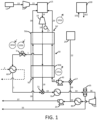
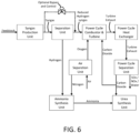
- fuel passes in line 13 from a fuel source 12, optionally being compressed in a fuel compressor 14, to be combusted in combustor 15.
- Oxidant pass through line 22 from oxidant source 25, which may, for example, and air separation unit, oxygen membrane, or other oxidant source.
- the oxidant may be passed directly to the combustor 15 but, as illustrated, the oxidant can be mixed with recycled CO 2 in mixer/union 27 before being compressed in pump 40 and passed in line 29 through the heat exchanger 50 on route to the combustor 15.
- the turbine exhaust stream in line 18 is passed through the heat exchanger 50, and a portion of the turbine exhaust stream exits the heat exchanger 50 in line 1 at an intermediate temperature.
- the heat exchanger 50 is shown as two separate heat exchange sections 50a and 50b; however, the dashed lines illustrate that the separate heat exchange sections may be connected as a single HEU operating with a plurality of sections (e.g., 2 or more, 3 or more, or even more portions) at different conditions.
- bypass heat exchanger 60 can use the bypass stream in line 1 as a heat source to provide thermal energy to any process outside of the illustrated power cycle. It should be noted that bypass heat exchanger 60 may simply be a dedicated section of the heat exchanger network 50 (e.g., bypass heat exchanger 60 may be integral to heat exchanger 50 and operated so that only the stream in line 1 passes therethrough for heat removal).
- valve 5 As intermediate temperatures within heat exchanger 50 approach maximum design limits, the controller providing control over valve 5 will send a signal to valve 5 to open. This will encourage the flow of the stream in line 1 through the bypass heat exchanger 60 before passing on to heat exchanger 70. If operating conditions (e.g., power demand) are such that the intermediate temperatures in heat exchanger 50 are below design limits, then valve 5 may remain closed (or be closed if previously opened) in order to bias the flow through the remainder of heat exchanger 50 (e.g., heat exchange section 50b). This has the benefit of improving the thermal recovery of the power cycle. Any number of bypasses may be integrated in parallel into heat exchanger 50 as a means of providing more finite temperature control at various parts of the exchanger train.
- control of the bypass line 1 may be effected based upon power output from the turbine 10 and the generator 17.
- a signal 101b indicating a change in power demand effective to cause an operational change of the turbine 10 altering power generation from the generator 17 of the power production plant can be received by the controller 100.
- the controller 100 can provide an output 102b that causes more or less fluid to pass through line 1.
- the power production cycle otherwise may continue in that the turbine exhaust in line 18 can merge with the bypass stream in line 1, such as in a mixer/union 21, prior to passage in line 19 to heat exchanger 70, wherein the exhaust stream is cooled to near ambient temperature.
- the exhaust stream then passes through 34 to separator 35 wherein a substantially pure stream of CO 2 is provided in line 36.
- the stream of CO 2 is then compressed in compressor 30, optionally cooled in heat exchanger 80, then pumped in pump 20 to the desired pressure range to be recycled back to the combustor 15 through line 39.
- a portion of the CO 2 stream in line 39 can be branched in line 38 and passed to the mixer/union 27, as referenced above, for admixture with the oxidant.
- a portion of the CO 2 in line 39 may be separated and passed through line 37 for export or other end use, such as EOR. Water from separator 35 can be passed out of the system through drain line 33.
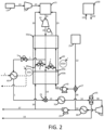
- FIG. 2 thus illustrates an embodiment, wherein elements already described in relation to FIG. 1 are substantially unchanged.
- the power production system can be configured to provide for recirculation of at least a portion of one or both of the flows passing through the heat exchanger 50 from pump 20 and pump 40.
- valve 6 can be utilized for recirculation of at least a portion of recycle CO 2 stream passing through the heat exchanger 50 in line 39 so that said portion of the recycle CO 2 stream is passed to the turbine exhaust stream in line 18.
- valve 7 can be utilized for recirculation of at least a portion of the oxidant stream passing through the heat exchanger 50 in line 29 so that said portion of the oxidant stream is passed to the turbine exhaust stream in line 18.
- Adjusting a heat profile of the HEU thus can include one or both of the following: causing a portion of a recycle stream being heated in the HEU to be passed to an exhaust stream being cooled in the HEU such that said adjusting is effective to increase the mass flow of the exhaust stream passing through a section of the HEU; and causing a portion of an oxidant stream being heated in the HEU to be passed to an exhaust stream being cooled in the HEU such that said adjusting is effective to increase the mass flow of the exhaust stream passing through a section of the HEU. More particularly, as the desired output of turbine 10 is increased, the discharge flow rates of pump 20 and/or pump 40 to the combustor 15 can be controlled to likewise increase as needed.
- valve 6 in line 39a or valve 7 in line 29a in the heat exchanger 50 will begin to close. This will not only deliver more mass flow to the combustor 15 (and ultimately to the turbine 10), but it will also increase the amount of thermal energy provided by the heat exchanger 50 to the combustor 15. Otherwise, when a power output of the turbine 15 is reduced, valve 6 and valve 7 can be opened as needed. This artificially increases the flow rate through the lower half of the heat exchanger 50 (e.g., through heat exchange section 50b) and quenches the turbine exhaust temperature to further help manage the heat exchanger temperature profile.
- the control function therefore can comprise causing one or both of a portion of the recycle stream and a portion of the oxidant stream to be passed to the exhaust stream responsive to one or both of the following inputs: a signal indicating a change in power demand effective to cause an operational change of a turbine altering power generation from the power production plant (see signal 101b in FIG. 1 ); and a signal indicating that a temperature within the HEU is within a defined threshold of a maximum operating temperature of the HEU (see signal 101a in FIG. 1 ).
- Output signals 102c and 102d may thus be generated for controlling fluid passage through valve 6 and valve 7, respectively.
- signals 101a and 101b are shown as example embodiments, it is understood that similar signals may be received from a variety of components of the present systems.
- input signals may be received by the controller from any of the pump 20, the pump 40, the compressor 30, the compressor 31, an IGV 32, the separator 35, the compressor 14, and any of the lines described herein.
- signals may relate information directed to a pressure at a certain point in the system, a flow rate at a certain point in the system, a temperature at a certain point in the system, a molar concentration of a compound at a certain point in the system, or any similar parameter that may be useful for implementing a control function as otherwise described herein.
- suitable input signals may include any one or more of the following: a power demand signal; a gasifier output signal (e.g., indicating that the syngas flow exceeds a defined threshold amount); a hydrogen demand signal (e.g., indicating that the hydrogen flow exceeds a defined threshold amount); a syngas chemistry signal from the gasifier (e.g., which can be indicative that the estimated or actual mole fraction of one or more components of the produced syngas exceeds a defined threshold); a signal defining a syngas chemistry for the syngas stream being sent to the power cycle (the mixed stream from the bypass and the reduced hydrogen syngas stream); a feedstock modification signal; an ASU operation signal; a nitrogen availability signal; a mixed fuel Wobbe index signal; and the like.
- output signals may be directed for control of any one or more of the above-exemplified components of the system in order to implement a control function as otherwise described herein.
- the heat exchanger bypass line 1 may be used to limit the rate of temperature change in the heat exchanger 50 in conjunction with the maximum flow rates of pump 20 and/or pump 40 being provided near instantaneously through the heat exchanger 50 with minimal use of the recirculation lines (29a, 39a).
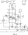
- a power cycle can be operated to utilize one or more recompression systems, and such systems likewise can be controlled so as to manage the flow through the recompression cycle to achieve intermediate temperature management in the heat exchanger 50.
- Recompression systems not only pressurize the recycle fluid but also provide low-grade heat to the power cycle's main recuperative heat exchanger (e.g., heat exchanger 50) as a means of recycle temperature optimization.
- FIG. 3 depicts a directly fired sCO 2 cycle with a recompression system originating from within the heat exchanger 50.
- compressor 31 in recompression line 3 by increasing its suction temperature (and thereby also its outlet temperature) as a constant outlet pressure is maintained. Energy consumption of compressor 31 will also be expected to increase in such embodiments. In some embodiments, this trend may be effectively reversed by actively reducing the flow rate through compressor 31 while maintaining a substantially constant outlet temperature for the exhaust stream in line 3.
- a controller for compressor 31 can actively monitor one or more check points on line 3 to ensure that the stream in line 3 does not exceed an optimized desired temperature by providing feedback to location of the inlet guide vane (IGV) 32 of the compressor 31.
- IGV inlet guide vane
- control function can comprise closing an inlet guide vane (IGV) 32 of the recirculation compressor 31 responsive to a signal indicating that a temperature within the HEU is within a defined threshold of a maximum operating temperature of the HEU (see, for example, signal 101a in FIG. 1 ).
- IGV inlet guide vane
- FIG. 3 Such output signal is shown in FIG. 3 as signal 102e.
- the IGVs are used to limit power consumption while maintaining a safe margin to surge. IGVs may be used to control discharge pressure through various controllers. However, in certain situations, the IGVs may be placed into manual control and forced open in order to increase the flow in the recycle lines. In such a case, the inventory of the system will increase.
- the IGVs of the compressor 31 can be closed in order to decrease exhaust flow through the unit.
- the reduction in flow and subsequent low-grade heat addition to the heat exchanger 50 can create a cascading effect where average heat exchanger temperature will reduce.
- the feedback of reducing flow and reducing suction temperature at the compressor 31 will converge upon a mode of operation where the requirement at the check point is satisfied. This will also lead to the lowest energy consumption at compressor 31 required to maximize the recycle temperature level that may be obtained with the heat exchanger 50.
- the IGVs of compressor 30 may need to open to allow it to pressurize an increased amount of flow.
- the suction temperature of compressor 31 may fall and so may the temperature check point on line 3. This would actually force the IGVs of compressor 31 to open to generate more heat.
- the IGVs of compressor 30 would need to close to account for increased flow at compressor 31.
- IGVs may be substituted with recirculation lines and coolers.
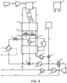
- a further heat source can be provided at an intermediate temperature in the heat exchanger 50.
- the heater 90 may operate by providing heat directly or indirectly.
- the source of heat can also vary such as it may come from electricity, solar, nuclear, or fuel combustion resources.
- the heater 90 may also be located on any of the streams within the heat exchanger network 50.
- heater 90 is an oxy-fired duct burner on the exhaust flow of turbine 10. Combusted fuel emissions freely mix with the turbine exhaust flow and contribute to a temperature rise. This addition of thermal energy may serve several purposes.
- heater 90 is located downstream of the bypass line 1, the recirculation lines 29a and 39a, and the recompression line 3, which are all described above.
- the plant may be essentially preheated while the balance of the cycle around turbine 10 operates in a substantially closed-loop manner.
- the bypass lines associated with valve 6 and/or valve 7 may divert part or all of their source flows.
- the design flow rates can be configured to accommodate over-speed protection of the turbine 10 in the event of a trip scenario.
- the heater 90 may be used to provide additional thermal energy for heat exchanger 60 to the extent that the temperature profile of the heat exchanger network 50 is minimally affected.
- the various temperature control schemes described herein can be used independently or in any combination with one or more of the further control schemes described herein. Should multiple temperature control schemes be used simultaneously, their activities can be prioritized in a manner as described herein.
- the use of heater 90 can negate this effect and allow heat recovery at heat exchanger 60 to merely share balance of plant resources with the power cycle.
- the outlet temperature of pump 20 can be controlled to its optimal value.
- the flow rate through the recompression system e.g., line 3 and compressor 31
- the flow rate through the recompression system can be minimized or maximized to the extent that the temperature at check point on line 3 approaches its optimal desired value.
- the power production plant can include a heater 90 that is configured for operation independent of the HEU 50.
- independent operation can mean simply that the heat provided by the heater 90 is from a source other than any heated stream that is used to provide heat exchange in the HEU 50.
- the heater 90 can be configured for addition of heat to the turbine exhaust stream 18 at a point that is positioned between the first HEU end 50' and the second HEU end 50".
- the heater 90 for example, can be a combustion heater. Further configurations and components can be identified based upon the further components that are illustrated in relation to FIG. 1 through FIG. 5 as already discussed above.
- the CO 2 may be at an elevated temperature prior to use in the downstream process, it may be desirable to heat it against the main recuperative heat exchanger train in the power production cycle counter-currently to the turbine exhaust flow path.
- the flow rate through the hot gas compressor can be increased by opening the inlet guide vanes ("IGVs") on the unit. This will serve the purpose of providing an increase in low-grade heat to the heat exchanger train. It will also reduce the total flow rate of CO 2 through the main CO 2 compressor. This will force the IGVs on this unit to close in order to accommodate the new conditions.
- IGVs inlet guide vanes
- the total gross power output at the turbine will not change given that the inlet conditions will remain the same as beforehand. There also won't be a change in fuel input to the facility given that the recycle CO 2 temperature has been maintained. Rather, the net power output of the plant will reduce given that the hot gas compressor operates less efficiently as a pressurization device than the main CO 2 compressor.
- the basic effect is that fuel has been converted to electricity to then be exported as thermal energy in the discharged CO 2 stream. All combustion and pressurization activities are inherently managed by the equipment and controls capabilities of the power cycle.
- the quality and quantity of heat to the downstream process may be varied by the amount of export CO 2 heated by the recuperative heat exchanger train as well as the total flow rate of CO 2 processed by the hot gas compressor.
- the presently disclosed systems and methods allow the hot gas compressor in the power production cycle to provide low grade heat for the optimization of the recuperative heat exchanger while also serving as a heat source for external industrial processes utilizing the cycle's export CO 2 as a feedstock and/or heat transfer fluid.
- the hot gas compressor is managed in such a way that the inlet conditions to the turbine (and therefore gross performance) do not change while heat is being provided to a downstream industrial process. Therefore, thermal cycling of the turbine does not occur.
- the net power output of the power production cycle is reduced given that the heat generated for the external industrial process increases the parasitic load of the hot gas compressor (i.e., effectively converting electricity back into thermal energy).
- urea synthesis may be particularly combined with the power cycle, and this can require an ammonia source.
- the necessary ammonia (NH 3 ) can be either a co-product of the underlying power production cycle, or it can be bought as a commodity (e.g., from outside ammonia plants).
- a power production cycle according to the present disclosure exporting CO 2 for urea synthesis can be carried out to provide a method for co-production of power and urea.
- CO 2 can be formed in the combustion process as otherwise described herein (e.g., taken as a product from line 37, taken at an increased temperature from some point in line 39, or taken at a lower pressure upstream from the pump 20).
- high grade heat of combustion can be recuperated from the combustor exhaust or a turbine exhaust stream (e.g., at a point from the heat exchanger 50) by counter-current heating of cold, recycle CO 2 to the required combustion inlet temperature.
- This can be specifically the pressurized stream exiting the pump 20.
- the IGV 32 of the compressor e.g., compressor 31
- the low grade heat e.g., at approximately a temperature of 150 to 300 °C
- the flow rate of CO 2 at the compressor inlet can be dictated by the amount of extra low grade heat required for downstream Urea synthesis.
- the IGV of the main compressor 30 can be closed to adjust CO 2 entering it correspondently.
- Total CO 2 at the primary heat exchanger 50 outlet can be sent to the separator 35 for liquid water removal, and SOx/NOx (if any) removal.
- CO 2 can be compressed and pumped to the required pressure (e.g., in compressor 30 and pump 20), and a portion of the CO 2 can be separated from the main CO 2 stream at a pressure of about 140-175 bar.
- the separated CO 2 can be directed into the primary heat exchanger 50 to be heated to about 190 °C, then this portion of CO 2 at about 140-175 bar and about 190 °C can be sent to the downstream Urea production unit.
- the power cycle can be utilized in relation to carbon capture, utilization, and storage in a saline aquifer.
- pressurized CO 2 e.g., from line 37
- the stream Prior to being injected below grade, the stream can be preheated to a temperature above the reservoir's water dew point through the systems and methods described herein utilizing a power production cycle.
- a portion of the liquid content is vaporized.
- a mixture of steam (desalinated water) and a portion of the injected CO 2 flow through an adjacent relief well allowing for the harvest of water and reuse of CO 2 at the surface.
- the reservoir has been depressurized allowing for further CO 2 storage.
- the system can comprise: a power production unit including at least a combustor, a turbine, a heat exchanger, and a separation unit, the power production unit being configured to receive a fuel stream and an oxidant and output power and substantially pure carbon dioxide; a syngas production unit configured to receive a feedstock and provide a syngas product, at least a portion of which is effective for use as at least a portion of the fuel stream in the power production unit; an air separation unit configured to provide oxygen for use as the oxidant in the power production unit and configured to provide nitrogen; and one or both of an ammonia synthesis unit and a urea synthesis unit.
- the ammonia synthesis unit specifically can be present. In such cases, it can be desirable for the ammonia synthesis unit to be configured to receive nitrogen from the air separation unit, configured to receive hydrogen from a hydrogen source, and configured to output ammonia.
- the hydrogen source can be a hydrogen separation unit configured to receive at least a portion of the syngas product from the syngas production unit and provide a stream of hydrogen and a stream of hydrogen-reduced syngas that is effective for use as at least a portion of the fuel stream in the power production unit.
- the systems and methods can incorporate the use of an optional bypass and control which can allow a portion of the syngas to bypass the hydrogen separation and proceed directly to the power cycle. This allows for more freedom of operation and a partial de-coupling of the gasifier, the power cycle, and the hydrogen production.
- the bypass line may be controlled based upon a variety of input signals that may be received by the controller (e.g., controller 100 in FIGs. 1-5 ).
- suitable input signals may include any one or more of the following: a power demand signal; a gasifier output signal (e.g., indicating that the syngas flow exceeds a defined threshold amount); a hydrogen demand signal (e.g., indicating that the hydrogen flow exceeds a defined threshold amount); a syngas chemistry signal from the gasifier (e.g., which can be indicative that the estimated or actual mole fraction of one or more components of the produced syngas exceeds a defined threshold); a signal defining a syngas chemistry for the syngas stream being sent to the power cycle (the mixed stream from the bypass and the reduced hydrogen syngas stream); a feedstock modification signal; an ASU operation signal; a nitrogen availability signal; a mixed fuel Wobbe index signal; and the like.
- a power demand signal e.g., indicating that the syngas flow exceeds a defined threshold amount
- a hydrogen demand signal e.g., indicating that the hydrogen flow exceeds a defined threshold amount
- a syngas chemistry signal from the gasifier
Landscapes
- Engineering & Computer Science (AREA)
- Chemical & Material Sciences (AREA)
- Combustion & Propulsion (AREA)
- Chemical Kinetics & Catalysis (AREA)
- Mechanical Engineering (AREA)
- General Engineering & Computer Science (AREA)
- Environmental & Geological Engineering (AREA)
- Biomedical Technology (AREA)
- Health & Medical Sciences (AREA)
- Analytical Chemistry (AREA)
- General Chemical & Material Sciences (AREA)
- Oil, Petroleum & Natural Gas (AREA)
- Life Sciences & Earth Sciences (AREA)
- Sustainable Development (AREA)
- Engine Equipment That Uses Special Cycles (AREA)
- Feedback Control In General (AREA)
- Supply And Distribution Of Alternating Current (AREA)
Claims (12)
- Ein Verfahren zur Kontrolle einer Leistungserzeugungsanlage, das Verfahren umfassend:Einstellen eines Wärmeprofils einer Wärmetauscheinheit (HEU) (50), welche mit einer Mehrzahl von Strömen arbeitet, die zwischen einem ersten HEU-Ende (50'), welches eine erste Betriebstemperatur aufweist, und einem zweiten HEU-Ende (50"), welches eine zweite, niedrigere Betriebstemperatur aufweist, hindurchtreten;wobei das Einstellen umfasst: Implementieren einer Kontrollfunktion, welche einen Massenstrom eines oder mehrerer der Mehrzahl von zwischen dem ersten HEU-Ende (50') und dem zweiten HEU-Ende (50") hindurchtretenden Strömen ändert durch Hinzufügen eines Massenstroms oder durch Entnehmen eines Massenstroms zu bzw. aus dem einen oder den mehreren der Mehrzahl von Strömen bei einem Zwischentemperaturbereich innerhalb der HEU (50) an einem Punkt, welcher zwischen dem ersten HEU-Ende (50') und dem zweiten HEU-Ende (50") positioniert ist;dadurch gekennzeichnet, dassdas Einstellen eines oder beides von Folgendem umfasst:Bewirken, dass ein Teil eines Recycle-Stroms, welcher in der HEU (50) erwärmt wird, zu einem Abgabestrom geleitet wird, der in der HEU (50) gekühlt wird, derart, dass mittels des Einstellens der Massenstrom des Abgabestroms, welcher durch einen Abschnitt der HEU (50) hindurchtritt, erhöhbar ist;Bewirken, dass ein Teil eines Oxidationsmittelstroms, welcher in der HEU (50) erwärmt wird, zu einem Abgabestrom geleitet wird, der in der HEU (50) gekühlt wird, derart, dass mittels des Einstellens der Massenstrom des Abgabestroms, welcher durch einen Abschnitt der HEU (50) hindurchtritt, erhöhbar ist.
- Das Verfahren nach Anspruch 1, wobei das Einstellen umfasst: Bewirken, dass ein Teil eines erwärmten Stroms, welcher durch die HEU (50) hindurchtritt, einen Abschnitt der HEU (50) durch eine Bypass-Leitung (1) hindurch umgeht, derart, dass mittels des Einstellens der Massenstrom des erwärmten Stroms, welcher durch den Abschnitt der HEU (50) hindurchtritt, der umgangen wird, erniedrigbar ist.
- Das Verfahren nach Anspruch 2, wobei der erwärmte Strom, welcher durch die HEU (50) hindurchtritt, ein erwärmter Turbinenabgabestrom von einer Turbine (10) ist, wobei der erwärmte Turbinenabgabestrom von dem ersten HEU-Ende (50') zu dem zweiten HEU-Ende (50") hindurchtritt, um einen gekühlten Turbinenabgabestrom bereitzustellen, und wobei der gekühlte Turbinenabgabestrom mittels eines oder mehreren von einem Separator (35), einem Verdichter (30) und einer Pumpe (20) weiterverarbeitet wird.
- Das Verfahren nach Anspruch 3, wobei die Kontrollfunktion umfasst:
Bewirken, dass der Teil des erwärmten Stroms, welcher durch die HEU (50) hindurchtritt, den Abschnitt der HEU (50) durch die Bypass-Leitung (1) hindurch umgeht, als Antwort auf eines oder beide der folgenden Signale, welche von einer Kontrolleinrichtung (100) empfangen werden:ein Signal, welches eine Änderung einer Leistungsanforderung angibt, mittels derer eine Betriebsänderung der Turbine (10) bewirkbar ist, welche eine Leistungserzeugung der Leistungserzeugungsanlage verändert;ein Signal, welches angibt, dass eine Temperatur innerhalb der HEU (50) innerhalb einer definierten Schwelle einer maximalen Betriebstemperatur der HEU (50) liegt. - Das Verfahren nach Anspruch 4, wobei die Kontrollfunktion umfasst:
Öffnen eines Ventils (5), welches in der Bypass-Leitung (1) positioniert ist; oder wobei der Teil des erwärmten Stroms, welcher durch die Bypass-Leitung (1) hindurchtritt, stromabwärts des zweiten HEU-Endes (50") und stromaufwärts eines oder mehrerer von dem Separator (35), dem Verdichter (30) und der Pumpe (20) wieder mit dem gekühlten Turbinenabgabestrom zusammengeführt wird. - Das Verfahren nach Anspruch 2, ferner umfassend: Bewirken, dass der Teil des erwärmten Stroms, welcher durch die Bypass-Leitung (1) hindurchtritt, mittels eines Bypass-Wärmetauschers (60) verarbeitet wird, mittels dessen Wärme von dem Teil des erwärmten Stroms in der Bypass-Leitung (1) auf einen oder mehrere weitere Ströme übertragbar ist.
- Das Verfahren nach Anspruch 1, wobei die Kontrollfunktion umfasst:
Bewirken, dass der jeweilige Teil des Recycle-Stroms und des Oxidationsmittelstroms als Antwort auf eines oder beide der folgenden Signale zu dem Abgabestrom geleitet wird:ein Signal, welches eine Änderung einer Leistungsanforderung angibt, mittels derer eine Betriebsänderung der Turbine (10) bewirkbar ist, welche eine Leistungserzeugung der Leistungserzeugungsanlage verändert;ein Signal, welches angibt, dass eine Temperatur innerhalb der HEU (50) innerhalb einer definierten Schwelle einer maximalen Betriebstemperatur der HEU (50) liegt. - Das Verfahren nach Anspruch 3, wobei die Leistungserzeugungsanlage einen Rezirkulationsverdichter (31) umfasst, welcher ausgebildet ist zum: Entnehmen eines Teils eines erwärmten Turbinenabgabestroms, welcher durch die HEU (50) hindurchtritt, Verdichten des Teils des erwärmten Turbinenabgabestroms, welcher entnommen wird, und Wiederzusammenführen des Teils des erwärmten Turbinenabgabestroms, welcher verdichtet wird, an einem stromabwärtsseitigen Abschnitt der HEU (50); oder
wobei die Kontrollfunktion umfasst: Schließen einer Einlassleitschaufel (IGV) (32) des Rezirkulationsverdichters (31) als Antwort auf ein Signal, welches angibt, dass eine Temperatur innerhalb der HEU (50) innerhalb einer definierten Schwelle einer maximalen Betriebstemperatur der HEU (50) liegt. - Das Verfahren nach Anspruch 1, ferner umfassend: Hinzufügen von Wärme zu einem oder mehreren der Mehrzahl von Strömen, welche zwischen dem ersten HEU-Ende (50') und dem zweiten HEU-Ende (50") hindurchtreten, wobei die Wärme bei einem Zwischentemperaturbereich innerhalb der HEU (50) an einem Punkt, welcher zwischen dem ersten HEU-Ende (50') und dem zweiten HEU-Ende (50") positioniert ist, hinzugefügt wird;
und wobei die Wärme unter Verwendung einer Heizeinrichtung (90) hinzugefügt wird, welche unabhängig von der HEU (50) betrieben wird; wobei optional die Heizeinrichtung (90) eine Verbrennungsheizeinrichtung ist; und wobei optional die Wärme einem Turbinenabgabestrom hinzugefügt wird, welcher durch die HEU (50) hindurchtritt, und wobei ein Abgabestrom von der Verbrennungsheizeinrichtung dem Turbinenabgabestrom direkt hinzugefügt wird. - Eine Leistungserzeugungsanlage, umfassend:eine Turbine (10);einen Leistungsgenerator (17);eine Wärmeaustauscheinheit (HEU) (50);einen oder mehrere Verdichter (30) oder Pumpen (20); undeine Kontrolleinheit (100);wobei die HEU (50) ausgebildet ist für einen Wärmeaustausch zwischen einer Mehrzahl von Strömen, welche zwischen einem ersten HEU-Ende (50'), welches eine erste Betriebstemperatur aufweist, und einem zweiten HEU-Ende (50"), welches eine zweite, niedrigere Betriebstemperatur aufweist, hindurchtreten;wobei die HEU (50) eine oder mehrere Komponenten umfasst, welche ausgebildet sind zum Hinzufügen eines Massenstroms oder zum Entnehmen eines Massenstroms zu bzw. aus einem oder mehreren der Mehrzahl von Strömen an einem Punkt, welcher zwischen dem ersten HEU-Ende (50') und dem zweiten HEU-Ende (50") positioniert ist, derart, dass ein Teil eines Fluids, welches durch den einen oder die mehreren der Mehrzahl von Strömen hindurchtritt, davon abgehalten wird, durch einen verbleibenden Abschnitt der HEU (50) hindurchzutreten; undwobei die Kontrolleinheit (100) dazu ausgebildet ist, ein Signal zu empfangen, welches einen Betriebszustand der Leistungserzeugungsanlage definiert, und darauf basierend ein Signal auszugeben, mittels dessen die eine oder die mehreren Komponenten, welche dazu ausgebildet sind, dem einen oder den mehreren der Mehrzahl von Strömen einen Massenstrom hinzufügen oder einen Massenstrom zu entnehmen, kontrollierbar sind; unddadurch gekennzeichnet, dass eine oder beide der folgenden Bedingungen erfüllt sind:die eine oder die mehreren Komponenten, welche dazu ausgebildet sind, einem oder mehreren der Mehrzahl von Strömen einen Massenstrom hinzuzufügen oder einen Massenstrom zu entnehmen, umfassen: eine Rezirkulationsleitung (39a) und ein Rezirkulationsventil (6), welche zwischen dem Turbinenabgabestrom und dem Recycle-Strom angeordnet sind;wobei die eine oder die mehreren Komponenten, welche dazu ausgebildet sind, einem oder mehreren der Mehrzahl von Strömen einen Massenstrom hinzuzufügen oder einen Massenstrom zu entnehmen, umfassen: eine Rezirkulationsleitung (29a) und ein Rezirkulationsventil (7), welche zwischen dem Turbinenabgabestrom und dem Oxidationsmittelstrom angeordnet sind.
- Die Leistungserzeugungsanlage nach Anspruch 10, wobei die HEU (50) ausgebildet ist für einen Wärmeaustausch zwischen mindestens einem Turbinenabgabestrom, welcher aus einer Turbine (10) austritt, und einem oder beiden von einem Recycle-Strom und einem Oxidationsmittelstrom; wobei optional die eine oder die mehreren Komponenten, welche dazu ausgebildet sind, einem oder mehreren der Mehrzahl von Strömen einen Massenstrom hinzuzufügen oder einen Massenstrom zu entnehmen, eine Bypass-Leitung (1) und ein Bypass-Ventil (5) umfassen, welche dazu ausgebildet sind, einen Teil des Turbinenabgabestroms um einen Abschnitt der HEU (50) herum umzuleiten; und wobei optional die Leistungserzeugungsanlage ferner einen Bypass-Wärmetauscher (60) umfasst, welcher mit der Bypass-Leitung (1) betreibbar ist und dazu ausgebildet ist, Wärme von dem Teil des Turbinenabgabestroms, der durch denselben hindurch umgeleitet wird, auf einen oder mehrere weitere Ströme zu übertragen.
- Die Leistungserzeugungsanlage nach Anspruch 11, ferner umfassend eine Heizeinrichtung (90), welche ausgebildet ist für einen von der HEU (50) unabhängigen Betrieb, wobei die Heizeinrichtung (90) ausgebildet ist zum Hinzufügen von Wärme zu dem Turbinenabgabestrom an einem Punkt, welcher zwischen dem ersten HEU-Ende (50') und dem zweiten HEU-Ende (50") positioniert ist; wobei optional die Heizeinrichtung (90) eine Verbrennungsheizeinrichtung ist.
Priority Applications (1)
| Application Number | Priority Date | Filing Date | Title |
|---|---|---|---|
| EP25153658.7A EP4520935A3 (de) | 2019-10-22 | 2020-10-22 | Steuerungsschemata zur wärmeverwaltung von stromerzeugungssystemen und -verfahren |
Applications Claiming Priority (2)
| Application Number | Priority Date | Filing Date | Title |
|---|---|---|---|
| US201962924525P | 2019-10-22 | 2019-10-22 | |
| PCT/IB2020/059956 WO2021079324A1 (en) | 2019-10-22 | 2020-10-22 | Control schemes for thermal management of power production systems and methods |
Related Child Applications (2)
| Application Number | Title | Priority Date | Filing Date |
|---|---|---|---|
| EP25153658.7A Division EP4520935A3 (de) | 2019-10-22 | 2020-10-22 | Steuerungsschemata zur wärmeverwaltung von stromerzeugungssystemen und -verfahren |
| EP25153658.7A Division-Into EP4520935A3 (de) | 2019-10-22 | 2020-10-22 | Steuerungsschemata zur wärmeverwaltung von stromerzeugungssystemen und -verfahren |
Publications (3)
| Publication Number | Publication Date |
|---|---|
| EP4048873A1 EP4048873A1 (de) | 2022-08-31 |
| EP4048873C0 EP4048873C0 (de) | 2025-04-09 |
| EP4048873B1 true EP4048873B1 (de) | 2025-04-09 |
Family
ID=73040182
Family Applications (2)
| Application Number | Title | Priority Date | Filing Date |
|---|---|---|---|
| EP25153658.7A Pending EP4520935A3 (de) | 2019-10-22 | 2020-10-22 | Steuerungsschemata zur wärmeverwaltung von stromerzeugungssystemen und -verfahren |
| EP20800335.0A Active EP4048873B1 (de) | 2019-10-22 | 2020-10-22 | Steuerungsschemata zur wärmeverwaltung von energieerzeugungssystemen und verfahren |
Family Applications Before (1)
| Application Number | Title | Priority Date | Filing Date |
|---|---|---|---|
| EP25153658.7A Pending EP4520935A3 (de) | 2019-10-22 | 2020-10-22 | Steuerungsschemata zur wärmeverwaltung von stromerzeugungssystemen und -verfahren |
Country Status (12)
| Country | Link |
|---|---|
| US (3) | US11549433B2 (de) |
| EP (2) | EP4520935A3 (de) |
| JP (2) | JP7585318B2 (de) |
| KR (1) | KR20220088460A (de) |
| CN (1) | CN114901925A (de) |
| AU (1) | AU2020369233A1 (de) |
| BR (1) | BR112022007588A2 (de) |
| CA (1) | CA3155211A1 (de) |
| ES (1) | ES3026689T3 (de) |
| MX (1) | MX2022004844A (de) |
| PL (1) | PL4048873T3 (de) |
| WO (1) | WO2021079324A1 (de) |
Families Citing this family (6)
| Publication number | Priority date | Publication date | Assignee | Title |
|---|---|---|---|---|
| US12253011B2 (en) * | 2020-12-28 | 2025-03-18 | China Three Gorges Corporation | Flexible power plant based on supercritical carbon dioxide power circulation in combination with seawater desalination and control method of same |
| KR20240105461A (ko) * | 2021-11-18 | 2024-07-05 | 8 리버스 캐피탈, 엘엘씨 | 단열 압축을 통한 이산화탄소 전력 사이클 |
| CN115387867B (zh) * | 2022-10-31 | 2023-03-24 | 中国核动力研究设计院 | 发电系统及基于发电系统的工质装载方法 |
| US12247515B2 (en) * | 2023-01-13 | 2025-03-11 | Southwest Research Institute | Power production plant including liquid oxygen storage and method of operation of the power production plant |
| EP4649228A1 (de) | 2023-01-13 | 2025-11-19 | Arbor Energy And Resources Corporation | Integriertes kohlenstoffsequestrierungs- und stromerzeugungssystem sowie verfahren zur verwendung |
| EP4642999A1 (de) * | 2023-01-25 | 2025-11-05 | Nuovo Pignone Tecnologie - S.R.L. | Sauerstoff-brennstoff-expandersystem mit mehreren wärmetauschern und verfahren |
Family Cites Families (227)
| Publication number | Priority date | Publication date | Assignee | Title |
|---|---|---|---|---|
| US3063247A (en) * | 1958-11-07 | 1962-11-13 | Union Carbide Corp | Low temperature purification of an impurity-containing gas |
| US3376706A (en) | 1965-06-28 | 1968-04-09 | Angelino Gianfranco | Method for obtaining mechanical energy from a thermal gas cycle with liquid phase compression |
| US3369361A (en) | 1966-03-07 | 1968-02-20 | Gale M. Craig | Gas turbine power plant with sub-atmospheric spray-cooled turbine discharge into exhaust compressor |
| CH476208A (de) | 1967-07-27 | 1969-07-31 | Sulzer Ag | Gasturbinenanlage mit CO2 als Arbeitsmittel |
| US3544291A (en) | 1968-04-22 | 1970-12-01 | Texaco Inc | Coal gasification process |
| US3736745A (en) | 1971-06-09 | 1973-06-05 | H Karig | Supercritical thermal power system using combustion gases for working fluid |
| US3816595A (en) | 1971-11-15 | 1974-06-11 | Aqua Chem Inc | Method and apparatus for removing nitrogen oxides from a gas stream |
| US4455614A (en) | 1973-09-21 | 1984-06-19 | Westinghouse Electric Corp. | Gas turbine and steam turbine combined cycle electric power generating plant having a coordinated and hybridized control system and an improved factory based method for making and testing combined cycle and other power plants and control systems therefor |
| US3868817A (en) | 1973-12-27 | 1975-03-04 | Texaco Inc | Gas turbine process utilizing purified fuel gas |
| US3971211A (en) | 1974-04-02 | 1976-07-27 | Mcdonnell Douglas Corporation | Thermodynamic cycles with supercritical CO2 cycle topping |
| US3976443A (en) | 1974-12-18 | 1976-08-24 | Texaco Inc. | Synthesis gas from solid carbonaceous fuel |
| US4132065A (en) | 1977-03-28 | 1979-01-02 | Texaco Inc. | Production of H2 and co-containing gas stream and power |
| US4191500A (en) | 1977-07-27 | 1980-03-04 | Rockwell International Corporation | Dense-phase feeder method |
| US4154581A (en) | 1978-01-12 | 1979-05-15 | Battelle Development Corporation | Two-zone fluid bed combustion or gasification process |
| US4275557A (en) | 1978-01-25 | 1981-06-30 | General Electric Company | Method and apparatus for controlling thrust in a gas turbine engine |
| US4206610A (en) | 1978-04-14 | 1980-06-10 | Arthur D. Little, Inc. | Method and apparatus for transporting coal as a coal/liquid carbon dioxide slurry |
| US4193259A (en) | 1979-05-24 | 1980-03-18 | Texaco Inc. | Process for the generation of power from carbonaceous fuels with minimal atmospheric pollution |
| US4350008A (en) | 1979-12-26 | 1982-09-21 | United Technologies Corporation | Method of starting turbine engines |
| JPS57117706A (en) | 1981-01-14 | 1982-07-22 | Tokyo Shibaura Electric Co | Start control of thermal power generation plant |
| US4702747A (en) | 1981-03-24 | 1987-10-27 | Carbon Fuels Corporation | Coal derived/carbon dioxide fuel slurry and method of manufacture |
| US4434613A (en) | 1981-09-02 | 1984-03-06 | General Electric Company | Closed cycle gas turbine for gaseous production |
| US4522628A (en) | 1981-12-16 | 1985-06-11 | Mobil Oil Corporation | Method for removing ash mineral matter of coal with liquid carbon dioxide and water |
| US4498289A (en) | 1982-12-27 | 1985-02-12 | Ian Osgerby | Carbon dioxide power cycle |
| US4982569A (en) | 1983-03-25 | 1991-01-08 | Ormat Turbines, Ltd. | Parallel hybrid system for generating power |
| US4622472A (en) | 1984-07-16 | 1986-11-11 | Ormat Turbines Ltd. | Hybrid electric power generating system |
| US4589255A (en) | 1984-10-25 | 1986-05-20 | Westinghouse Electric Corp. | Adaptive temperature control system for the supply of steam to a steam turbine |
| US4602483A (en) | 1985-03-08 | 1986-07-29 | Southwestern Public Service Company | Coal slurry system |
| US4765781A (en) | 1985-03-08 | 1988-08-23 | Southwestern Public Service Company | Coal slurry system |
| DE3600432A1 (de) | 1985-05-21 | 1987-02-05 | Gutehoffnungshuette Man | Verfahren zum vergasen eines kohlenstoffhaltigen brennstoffs, insbesondere kohle |
| US4721420A (en) | 1985-09-03 | 1988-01-26 | Arthur D. Little, Inc. | Pipeline transportation of coarse coal-liquid carbon dioxide slurry |
| US4735052A (en) | 1985-09-30 | 1988-04-05 | Kabushiki Kaisha Toshiba | Gas turbine apparatus |
| GB2196016B (en) | 1986-08-29 | 1991-05-15 | Humphreys & Glasgow Ltd | Clean electric power generation process |
| US4999995A (en) | 1986-08-29 | 1991-03-19 | Enserch International Investments Ltd. | Clean electric power generation apparatus |
| US4754607A (en) * | 1986-12-12 | 1988-07-05 | Allied-Signal Inc. | Power generating system |
| US4765143A (en) | 1987-02-04 | 1988-08-23 | Cbi Research Corporation | Power plant using CO2 as a working fluid |
| US4839030A (en) | 1988-05-27 | 1989-06-13 | Hri, Inc. | Coal liquefaction process utilizing coal/CO2 slurry feedstream |
| US4957515A (en) | 1988-11-03 | 1990-09-18 | Air Products And Chemicals, Inc. | Process for sulfur removal and recovery from fuel gas using physical solvent |
| JP2664984B2 (ja) | 1989-02-28 | 1997-10-22 | 三菱重工業株式会社 | 難燃性低発熱量ガスの燃焼装置 |
| US5247791A (en) | 1989-10-25 | 1993-09-28 | Pyong S. Pak | Power generation plant and power generation method without emission of carbon dioxide |
| US5175995A (en) | 1989-10-25 | 1993-01-05 | Pyong-Sik Pak | Power generation plant and power generation method without emission of carbon dioxide |
| JP2954972B2 (ja) | 1990-04-18 | 1999-09-27 | 三菱重工業株式会社 | ガス化ガス燃焼ガスタービン発電プラント |
| US5353721A (en) | 1991-07-15 | 1994-10-11 | Manufacturing And Technology Conversion International | Pulse combusted acoustic agglomeration apparatus and process |
| JP3110114B2 (ja) | 1991-11-01 | 2000-11-20 | 丙植 朴 | Co▲2▼回収発電プラント |
| US5421166A (en) | 1992-02-18 | 1995-06-06 | Air Products And Chemicals, Inc. | Integrated air separation plant-integrated gasification combined cycle power generator |
| FI945602A7 (fi) | 1992-05-29 | 1994-11-28 | Kvaerner Pulping Tech Ab | Menetelmä energian saamiseksi talteen poltettavissa olevasta kaasusta |
| US5295350A (en) | 1992-06-26 | 1994-03-22 | Texaco Inc. | Combined power cycle with liquefied natural gas (LNG) and synthesis or fuel gas |
| NL9201179A (nl) | 1992-07-02 | 1994-02-01 | Tno | Werkwijze voor het regeneratief verwijderen van kooldioxide uit gasstromen. |
| JPH0626362A (ja) | 1992-07-09 | 1994-02-01 | Mitsubishi Heavy Ind Ltd | Co▲2▼ガスタービンサイクル |
| SE9202155L (sv) | 1992-07-13 | 1993-08-16 | Bal Ab | Kombinerad foerbraennings- och avgasreningsanlaeggning |
| US6289666B1 (en) | 1992-10-27 | 2001-09-18 | Ginter Vast Corporation | High efficiency low pollution hybrid Brayton cycle combustor |
| US5937652A (en) | 1992-11-16 | 1999-08-17 | Abdelmalek; Fawzy T. | Process for coal or biomass fuel gasification by carbon dioxide extracted from a boiler flue gas stream |
| JPH06323165A (ja) | 1993-05-17 | 1994-11-22 | Hitachi Ltd | ガスタービン用制御装置及び制御方法 |
| US5415673A (en) | 1993-10-15 | 1995-05-16 | Texaco Inc. | Energy efficient filtration of syngas cooling and scrubbing water |
| US5345756A (en) | 1993-10-20 | 1994-09-13 | Texaco Inc. | Partial oxidation process with production of power |
| US5417052A (en) | 1993-11-05 | 1995-05-23 | Midwest Research Institute | Hybrid solar central receiver for combined cycle power plant |
| JP3454372B2 (ja) | 1994-02-04 | 2003-10-06 | 石川島播磨重工業株式会社 | クローズドサイクルガスタービンの燃焼方法及び装置 |
| DE4407619C1 (de) | 1994-03-08 | 1995-06-08 | Entec Recycling Und Industriea | Verfahren zur schadstoffarmen Umwandlung fossiler Brennstoffe in technische Arbeit |
| CA2198252C (en) | 1994-08-25 | 2005-05-10 | Rudi Beichel | Reduced pollution power generation system and gas generator therefore |
| GB9425691D0 (en) | 1994-12-20 | 1995-02-22 | Boc Group Plc | A combustion apparatus |
| US5595059A (en) | 1995-03-02 | 1997-01-21 | Westingthouse Electric Corporation | Combined cycle power plant with thermochemical recuperation and flue gas recirculation |
| US6170264B1 (en) | 1997-09-22 | 2001-01-09 | Clean Energy Systems, Inc. | Hydrocarbon combustion power generation system with CO2 sequestration |
| US5724805A (en) | 1995-08-21 | 1998-03-10 | University Of Massachusetts-Lowell | Power plant with carbon dioxide capture and zero pollutant emissions |
| US5664414A (en) | 1995-08-31 | 1997-09-09 | Ormat Industries Ltd. | Method of and apparatus for generating power |
| US5906806A (en) | 1996-10-16 | 1999-05-25 | Clark; Steve L. | Reduced emission combustion process with resource conservation and recovery options "ZEROS" zero-emission energy recycling oxidation system |
| US6092362A (en) | 1996-11-27 | 2000-07-25 | Hitachi, Ltd. | Gas-turbine combustor with load-responsive premix burners |
| EP0859136A1 (de) | 1997-02-17 | 1998-08-19 | N.V. Kema | Gasturbine mit Energie-Rückgewinnung |
| NO308400B1 (no) | 1997-06-06 | 2000-09-11 | Norsk Hydro As | Kraftgenereringsprosess omfattende en forbrenningsprosess |
| EP0939199B1 (de) | 1998-02-25 | 2004-03-31 | ALSTOM Technology Ltd | Kraftwerksanlage und Verfahren zum Betrieb einer Kraftwerksanlage mit einem CO2-Prozess |
| EP0949405B1 (de) | 1998-04-07 | 2006-05-31 | Mitsubishi Heavy Industries, Ltd. | Turbinenanlage |
| DK0953748T3 (da) | 1998-04-28 | 2004-06-07 | Alstom Switzerland Ltd | Kraftværksanlæg med en CO2-proces |
| US6148602A (en) | 1998-08-12 | 2000-11-21 | Norther Research & Engineering Corporation | Solid-fueled power generation system with carbon dioxide sequestration and method therefor |
| JP2000120447A (ja) | 1998-10-12 | 2000-04-25 | Toshiba Corp | 火力発電プラント |
| US6199364B1 (en) | 1999-01-22 | 2001-03-13 | Alzeta Corporation | Burner and process for operating gas turbines with minimal NOx emissions |
| US6209307B1 (en) | 1999-05-05 | 2001-04-03 | Fpl Energy, Inc. | Thermodynamic process for generating work using absorption and regeneration |
| JP2000337107A (ja) | 1999-05-27 | 2000-12-05 | Mitsubishi Heavy Ind Ltd | クローズドガスタービンプラント |
| US6202574B1 (en) | 1999-07-09 | 2001-03-20 | Abb Alstom Power Inc. | Combustion method and apparatus for producing a carbon dioxide end product |
| JP4094185B2 (ja) | 1999-08-24 | 2008-06-04 | 三井造船株式会社 | 冷熱利用発電システム |
| NL1013804C2 (nl) | 1999-12-09 | 2001-06-12 | Wouter Willem Van De Waal | Milieuvriendelijke werkwijze voor het opwekken van energie uit aardgas. |
| US6196000B1 (en) | 2000-01-14 | 2001-03-06 | Thermo Energy Power Systems, Llc | Power system with enhanced thermodynamic efficiency and pollution control |
| DE10016079A1 (de) | 2000-03-31 | 2001-10-04 | Alstom Power Nv | Verfahren zum Entfernen von Kohlendioxid aus dem Abgas einer Gasturbinenanlage sowie Vorrichtung zur Durchführung des Verfahrens |
| AU2001276823A1 (en) | 2000-05-12 | 2001-12-03 | Clean Energy Systems, Inc. | Semi-closed brayton cycle gas turbine power systems |
| SE518487C2 (sv) | 2000-05-31 | 2002-10-15 | Norsk Hydro As | Metod att driva en förbränningsanläggning samt en förbränningsanläggning |
| US6333015B1 (en) | 2000-08-08 | 2001-12-25 | Arlin C. Lewis | Synthesis gas production and power generation with zero emissions |
| DK1197258T3 (da) * | 2000-10-13 | 2011-04-04 | Alstom Technology Ltd | Fremgangsmåde til drift af et kraftværksanlæg |
| US20020078694A1 (en) | 2000-12-22 | 2002-06-27 | Nazeer Waseem A. | Method to enhance fuel atomization for a liquid fuel combustor |
| DE10064270A1 (de) | 2000-12-22 | 2002-07-11 | Alstom Switzerland Ltd | Verfahren zum Betrieb einer Gasturbinenanlage sowie eine diesbezügliche Gasturbinenanlage |
| FR2819583B1 (fr) | 2001-01-12 | 2003-03-07 | Air Liquide | Procede integre de separation d'air et de generation d'energie et installation pour la mise en oeuvre d'un tel procede |
| FR2819584B1 (fr) | 2001-01-12 | 2003-03-07 | Air Liquide | Procede integre de separation d'air et de generation d'energie et installation pour la mise en oeuvre d'un tel procede |
| AU2002320400A1 (en) | 2001-02-12 | 2002-11-25 | Lucien Yehuda Bronicki | Method of and apparatus for producing uninterruptible power |
| WO2002084091A1 (en) | 2001-04-09 | 2002-10-24 | Hitachi, Ltd. | Gas turbine power generator |
| US6532743B1 (en) | 2001-04-30 | 2003-03-18 | Pratt & Whitney Canada Corp. | Ultra low NOx emissions combustion system for gas turbine engines |
| US6463738B1 (en) | 2001-05-21 | 2002-10-15 | Active Power, Inc. | Method and apparatus for providing a continuous supply of electric power |
| US20030213246A1 (en) | 2002-05-15 | 2003-11-20 | Coll John Gordon | Process and device for controlling the thermal and electrical output of integrated micro combined heat and power generation systems |
| US6598397B2 (en) | 2001-08-10 | 2003-07-29 | Energetix Micropower Limited | Integrated micro combined heat and power system |
| US20030221409A1 (en) | 2002-05-29 | 2003-12-04 | Mcgowan Thomas F. | Pollution reduction fuel efficient combustion turbine |
| EP1432889B1 (de) | 2001-10-01 | 2006-07-12 | Alstom Technology Ltd | Verfahren und vorrichtung zum anfahren von emissionsfreien gasturbinenkraftwerken |
| WO2003049122A2 (en) | 2001-12-03 | 2003-06-12 | Clean Energy Systems, Inc. | Coal and syngas fueled power generation systems featuring zero atmospheric emissions |
| JP3814206B2 (ja) | 2002-01-31 | 2006-08-23 | 三菱重工業株式会社 | 二酸化炭素回収プロセスの排熱利用方法 |
| US7284362B2 (en) | 2002-02-11 | 2007-10-23 | L'Air Liquide, Société Anonyme à Directoire et Conseil de Surveillance pour l'Étude et l'Exploitation des Procedes Georges Claude | Integrated air separation and oxygen fired power generation system |
| US6871502B2 (en) | 2002-02-15 | 2005-03-29 | America Air Liquide, Inc. | Optimized power generation system comprising an oxygen-fired combustor integrated with an air separation unit |
| US6532745B1 (en) | 2002-04-10 | 2003-03-18 | David L. Neary | Partially-open gas turbine cycle providing high thermal efficiencies and ultra-low emissions |
| US20030213854A1 (en) | 2002-05-15 | 2003-11-20 | Stickford George H. | Evaporator configuration for a micro combined heat and power system |
| NO20023050L (no) | 2002-06-21 | 2003-12-22 | Fleischer & Co | Fremgangsmåte samt anlegg for utf degree relse av fremgangsmåten |
| US20040011057A1 (en) | 2002-07-16 | 2004-01-22 | Siemens Westinghouse Power Corporation | Ultra-low emission power plant |
| US6820689B2 (en) | 2002-07-18 | 2004-11-23 | Production Resources, Inc. | Method and apparatus for generating pollution free electrical energy from hydrocarbons |
| US6802178B2 (en) | 2002-09-12 | 2004-10-12 | The Boeing Company | Fluid injection and injection method |
| US6775987B2 (en) | 2002-09-12 | 2004-08-17 | The Boeing Company | Low-emission, staged-combustion power generation |
| AU2003260832A1 (en) | 2002-09-17 | 2004-04-08 | Foster Wheeler Energy Corporation | Advanced hybrid coal gasification cycle utilizing a recycled working fluid |
| JP2004132255A (ja) | 2002-10-10 | 2004-04-30 | Mitsubishi Heavy Ind Ltd | 燃焼器制御装置 |
| US7303597B2 (en) | 2002-10-15 | 2007-12-04 | Pratt & Whitney Rocketdyne, Inc. | Method and apparatus for continuously feeding and pressurizing a solid material into a high pressure system |
| CA2505354C (en) | 2002-11-08 | 2012-04-03 | Alstom Technology Ltd. | Gas turbine power plant and method of operating the same |
| US7191587B2 (en) | 2002-11-13 | 2007-03-20 | American Air Liquide, Inc. | Hybrid oxygen-fired power generation system |
| DK1576266T3 (en) | 2002-11-15 | 2014-12-01 | Clean Energy Systems Inc | Low pollutant energy generation system with air separation using an ion transfer membrane |
| US6745574B1 (en) * | 2002-11-27 | 2004-06-08 | Elliott Energy Systems, Inc. | Microturbine direct fired absorption chiller |
| US6898936B1 (en) | 2002-12-04 | 2005-05-31 | The United States Of America As Represented By The United States Department Of Energy | Compression stripping of flue gas with energy recovery |
| US7007474B1 (en) | 2002-12-04 | 2006-03-07 | The United States Of America As Represented By The United States Department Of Energy | Energy recovery during expansion of compressed gas using power plant low-quality heat sources |
| EP1429000A1 (de) | 2002-12-09 | 2004-06-16 | Siemens Aktiengesellschaft | Verfahren und Vorrichtung zum Betrieb einer Gasturbine mit einer fossilbefeuerten Brennkammer |
| US6993912B2 (en) | 2003-01-23 | 2006-02-07 | Pratt & Whitney Canada Corp. | Ultra low Nox emissions combustion system for gas turbine engines |
| US7021063B2 (en) | 2003-03-10 | 2006-04-04 | Clean Energy Systems, Inc. | Reheat heat exchanger power generation systems |
| US7074033B2 (en) | 2003-03-22 | 2006-07-11 | David Lloyd Neary | Partially-open fired heater cycle providing high thermal efficiencies and ultra-low emissions |
| US7007486B2 (en) | 2003-03-26 | 2006-03-07 | The Boeing Company | Apparatus and method for selecting a flow mixture |
| GB2401403B (en) | 2003-05-08 | 2006-05-31 | Rolls Royce Plc | Carbon dioxide recirculation |
| US7192569B2 (en) | 2003-06-30 | 2007-03-20 | Pratt & Whitney | Hydrogen generation with efficient byproduct recycle |
| WO2005031136A1 (en) | 2003-09-30 | 2005-04-07 | Bhp Billiton Innovation Pty Ltd | Power generation |
| US7469544B2 (en) | 2003-10-10 | 2008-12-30 | Pratt & Whitney Rocketdyne | Method and apparatus for injecting a fuel into a combustor assembly |
| US7017329B2 (en) | 2003-10-10 | 2006-03-28 | United Technologies Corporation | Method and apparatus for mixing substances |
| US7124589B2 (en) | 2003-12-22 | 2006-10-24 | David Neary | Power cogeneration system and apparatus means for improved high thermal efficiencies and ultra-low emissions |
| DE10360951A1 (de) | 2003-12-23 | 2005-07-28 | Alstom Technology Ltd | Wärmekraftanlage mit sequentieller Verbrennung und reduziertem CO2-Ausstoß sowie Verfahren zum Betreiben einer derartigen Anlage |
| US7111463B2 (en) | 2004-01-23 | 2006-09-26 | Pratt & Whitney Rocketdyne Inc. | Combustion wave ignition for combustors |
| FR2867463B1 (fr) | 2004-03-15 | 2007-05-11 | Commissariat Energie Atomique | Alimentation en solide de granulometrie variable d'un dispositif sous pression |
| WO2005100754A2 (en) | 2004-04-16 | 2005-10-27 | Clean Energy Systems, Inc. | Zero emissions closed rankine cycle power system |
| EP2278222A1 (de) | 2004-05-19 | 2011-01-26 | Innovative Energy, Inc. | Verbrennungsverfahren und Verbrennungsvorrichtung |
| US7547419B2 (en) | 2004-06-16 | 2009-06-16 | United Technologies Corporation | Two phase injector for fluidized bed reactor |
| US7360639B2 (en) | 2004-06-16 | 2008-04-22 | Pratt & Whitney Rocketdyne, Inc. | Hot rotary screw pump |
| DE102004039164A1 (de) | 2004-08-11 | 2006-03-02 | Alstom Technology Ltd | Verfahren zur Erzeugung von Energie in einer eine Gasturbine umfassenden Energieerzeugungsanlage sowie Energieerzeugungsanlage zur Durchführung des Verfahrens |
| US7459131B2 (en) | 2004-08-16 | 2008-12-02 | United Technologies Corporation | Reduced temperature regernerating/calcining apparatus for hydrogen generation |
| US7402188B2 (en) | 2004-08-31 | 2008-07-22 | Pratt & Whitney Rocketdyne, Inc. | Method and apparatus for coal gasifier |
| JP2006125767A (ja) | 2004-10-29 | 2006-05-18 | Tokyo Institute Of Technology | 熱交換器 |
| US7736599B2 (en) | 2004-11-12 | 2010-06-15 | Applied Materials, Inc. | Reactor design to reduce particle deposition during process abatement |
| EP1657409A1 (de) | 2004-11-15 | 2006-05-17 | Elsam A/S | Methode und Vorrichtung zur Erzeugung von Strom |
| EP1669572A1 (de) | 2004-12-08 | 2006-06-14 | Vrije Universiteit Brussel | Verfahren und Anlage zur Herstellung von elektrischer Energie |
| JP2008522634A (ja) | 2004-12-13 | 2008-07-03 | エフ.ホフマン−ラ ロシュ アーゲー | 2型糖尿病に関連した単一ヌクレオチド多型(snp) |
| JP3110114U (ja) | 2005-01-31 | 2005-06-16 | 旭文 廖 | 防水型led発光装置 |
| US7395670B1 (en) | 2005-02-18 | 2008-07-08 | Praxair Technology, Inc. | Gas turbine fuel preparation and introduction method |
| US7269952B2 (en) | 2005-03-02 | 2007-09-18 | General Electric Company | Method and apparatus for gas turbine dry low NOx combustor corrected parameter control |
| US7547423B2 (en) | 2005-03-16 | 2009-06-16 | Pratt & Whitney Rocketdyne | Compact high efficiency gasifier |
| CA2603529A1 (en) | 2005-04-05 | 2006-10-12 | Sargas As | Low co2 thermal powerplant |
| US8196848B2 (en) | 2005-04-29 | 2012-06-12 | Pratt & Whitney Rocketdyne, Inc. | Gasifier injector |
| US7717046B2 (en) | 2005-04-29 | 2010-05-18 | Pratt & Whitney Rocketdyne, Inc. | High pressure dry coal slurry extrusion pump |
| NO332159B1 (no) | 2006-01-13 | 2012-07-09 | Nebb Technology As | Fremgangsmate og anlegg for energieffektiv oppfanging og utskillelse av CO2 fra en gassfase |
| US7950243B2 (en) | 2006-01-16 | 2011-05-31 | Gurin Michael H | Carbon dioxide as fuel for power generation and sequestration system |
| US8075646B2 (en) | 2006-02-09 | 2011-12-13 | Siemens Energy, Inc. | Advanced ASU and HRSG integration for improved integrated gasification combined cycle efficiency |
| US7665291B2 (en) | 2006-04-04 | 2010-02-23 | General Electric Company | Method and system for heat recovery from dirty gaseous fuel in gasification power plants |
| US7827797B2 (en) | 2006-09-05 | 2010-11-09 | General Electric Company | Injection assembly for a combustor |
| US7387197B2 (en) | 2006-09-13 | 2008-06-17 | Pratt & Whitney Rocketdyne, Inc. | Linear tractor dry coal extrusion pump |
| US7722690B2 (en) | 2006-09-29 | 2010-05-25 | Kellogg Brown & Root Llc | Methods for producing synthesis gas |
| US7827778B2 (en) | 2006-11-07 | 2010-11-09 | General Electric Company | Power plants that utilize gas turbines for power generation and processes for lowering CO2 emissions |
| US20080115500A1 (en) | 2006-11-15 | 2008-05-22 | Scott Macadam | Combustion of water borne fuels in an oxy-combustion gas generator |
| US7966829B2 (en) | 2006-12-11 | 2011-06-28 | General Electric Company | Method and system for reducing CO2 emissions in a combustion stream |
| WO2008076947A2 (en) | 2006-12-16 | 2008-06-26 | Papile Christopher J | Methods and/or systems for removing carbon dioxide and/or generating power |
| US7740671B2 (en) | 2006-12-18 | 2010-06-22 | Pratt & Whitney Rocketdyne, Inc. | Dump cooled gasifier |
| US7934383B2 (en) | 2007-01-04 | 2011-05-03 | Siemens Energy, Inc. | Power generation system incorporating multiple Rankine cycles |
| US7553463B2 (en) | 2007-01-05 | 2009-06-30 | Bert Zauderer | Technical and economic optimization of combustion, nitrogen oxides, sulfur dioxide, mercury, carbon dioxide, coal ash and slag and coal slurry use in coal fired furnaces/boilers |
| AT504863B1 (de) | 2007-01-15 | 2012-07-15 | Siemens Vai Metals Tech Gmbh | Verfahren und anlage zur erzeugung von elektrischer energie in einem gas- und dampfturbinen (gud) - kraftwerk |
| US8088196B2 (en) | 2007-01-23 | 2012-01-03 | Air Products And Chemicals, Inc. | Purification of carbon dioxide |
| US7731783B2 (en) | 2007-01-24 | 2010-06-08 | Pratt & Whitney Rocketdyne, Inc. | Continuous pressure letdown system |
| US8771604B2 (en) | 2007-02-06 | 2014-07-08 | Aerojet Rocketdyne Of De, Inc. | Gasifier liner |
| US20080190214A1 (en) | 2007-02-08 | 2008-08-14 | Pratt & Whitney Rocketdyne, Inc. | Cut-back flow straightener |
| RU2468214C2 (ru) * | 2007-03-30 | 2012-11-27 | Сименс Акциенгезелльшафт | Устройство с паровой турбиной и конденсатором и способ его работы |
| US7826054B2 (en) | 2007-05-04 | 2010-11-02 | Pratt & Whitney Rocketdyne, Inc. | Fuel cell instrumentation system |
| US7874140B2 (en) | 2007-06-08 | 2011-01-25 | Foster Wheeler North America Corp. | Method of and power plant for generating power by oxyfuel combustion |
| US8850789B2 (en) | 2007-06-13 | 2014-10-07 | General Electric Company | Systems and methods for power generation with exhaust gas recirculation |
| US7814975B2 (en) | 2007-09-18 | 2010-10-19 | Vast Power Portfolio, Llc | Heavy oil recovery with fluid water and carbon dioxide |
| WO2009041617A1 (ja) | 2007-09-28 | 2009-04-02 | Central Research Institute Of Electric Power Industry | タービン設備及び発電設備 |
| EP2071157B1 (de) | 2007-12-10 | 2014-01-15 | Alstom Technology Ltd | Verfahren zur Regelung einer Gasturbine in einem Kraftwerk |
| JP5490023B2 (ja) | 2008-03-05 | 2014-05-14 | アルストム テクノロジー リミテッド | 発電所におけるガスタービンの制御方法およびその方法を実施する発電所 |
| US20090260585A1 (en) | 2008-04-22 | 2009-10-22 | Foster Wheeler Energy Corporation | Oxyfuel Combusting Boiler System and a Method of Generating Power By Using the Boiler System |
| US20090301054A1 (en) | 2008-06-04 | 2009-12-10 | Simpson Stanley F | Turbine system having exhaust gas recirculation and reheat |
| US20100018218A1 (en) | 2008-07-25 | 2010-01-28 | Riley Horace E | Power plant with emissions recovery |
| US20100024433A1 (en) | 2008-07-30 | 2010-02-04 | John Frederick Ackermann | System and method of operating a gas turbine engine with an alternative working fluid |
| US20100024378A1 (en) | 2008-07-30 | 2010-02-04 | John Frederick Ackermann | System and method of operating a gas turbine engine with an alternative working fluid |
| US8806849B2 (en) | 2008-07-30 | 2014-08-19 | The University Of Wyoming | System and method of operating a power generation system with an alternative working fluid |
| CH699804A1 (de) * | 2008-10-29 | 2010-04-30 | Alstom Technology Ltd | Gasturbinenanlage mit Abgasrückführung sowie Verfahren zum Betrieb einer solchen Anlage. |
| US8596075B2 (en) | 2009-02-26 | 2013-12-03 | Palmer Labs, Llc | System and method for high efficiency power generation using a carbon dioxide circulating working fluid |
| US10018115B2 (en) | 2009-02-26 | 2018-07-10 | 8 Rivers Capital, Llc | System and method for high efficiency power generation using a carbon dioxide circulating working fluid |
| CN102414511B (zh) | 2009-02-26 | 2014-09-24 | 帕尔默实验室有限责任公司 | 在高温高压下燃烧燃料的设备和方法及相关系统和装置 |
| US9068743B2 (en) | 2009-02-26 | 2015-06-30 | 8 Rivers Capital, LLC & Palmer Labs, LLC | Apparatus for combusting a fuel at high pressure and high temperature, and associated system |
| US8986002B2 (en) | 2009-02-26 | 2015-03-24 | 8 Rivers Capital, Llc | Apparatus for combusting a fuel at high pressure and high temperature, and associated system |
| US20100326084A1 (en) | 2009-03-04 | 2010-12-30 | Anderson Roger E | Methods of oxy-combustion power generation using low heating value fuel |
| US8099227B2 (en) | 2009-03-19 | 2012-01-17 | Pratt & Whitney Canada Corp. | Control of gas turbine engine |
| DE102009056707A1 (de) * | 2009-04-18 | 2010-10-21 | Alstom Technology Ltd. | Dampfkraftwerk mit Solarkollektoren |
| WO2010143622A1 (ja) | 2009-06-09 | 2010-12-16 | 三菱重工業株式会社 | 太陽熱受熱器 |
| JP2010285965A (ja) | 2009-06-15 | 2010-12-24 | Mitsubishi Heavy Ind Ltd | 太陽熱ガスタービン発電装置 |
| US8685120B2 (en) | 2009-08-11 | 2014-04-01 | General Electric Company | Method and apparatus to produce synthetic gas |
| US8327641B2 (en) | 2009-12-01 | 2012-12-11 | General Electric Company | System for generation of power using solar energy |
| EP2333409A1 (de) | 2009-12-04 | 2011-06-15 | Son S.R.L. | Wärmerückgewinnungs-Dampfgenerator, Verfahren zur Stärkung eines Wärmerückgewinnungs-Dampfgenerators sowie zugehöriges Verfahren Stromerzeugung |
| US8545681B2 (en) * | 2009-12-23 | 2013-10-01 | General Electric Company | Waste heat driven desalination process |
| SG186157A1 (en) | 2010-07-02 | 2013-01-30 | Exxonmobil Upstream Res Co | Stoichiometric combustion of enriched air with exhaust gas recirculation |
| KR20140007328A (ko) | 2010-09-07 | 2014-01-17 | 예다 리서치 앤드 디벨럽먼트 캄파니 리미티드 | 에너지 생성 시스템 및 그 방법 |
| US8220248B2 (en) | 2010-09-13 | 2012-07-17 | Membrane Technology And Research, Inc | Power generation process with partial recycle of carbon dioxide |
| US8869889B2 (en) | 2010-09-21 | 2014-10-28 | Palmer Labs, Llc | Method of using carbon dioxide in recovery of formation deposits |
| US9410481B2 (en) | 2010-09-21 | 2016-08-09 | 8 Rivers Capital, Llc | System and method for high efficiency power generation using a nitrogen gas working fluid |
| US20120067054A1 (en) | 2010-09-21 | 2012-03-22 | Palmer Labs, Llc | High efficiency power production methods, assemblies, and systems |
| US9546814B2 (en) | 2011-03-16 | 2017-01-17 | 8 Rivers Capital, Llc | Cryogenic air separation method and system |
| TWI564474B (zh) | 2011-03-22 | 2017-01-01 | 艾克頌美孚上游研究公司 | 於渦輪系統中控制化學計量燃燒的整合系統和使用彼之產生動力的方法 |
| US20130081395A1 (en) | 2011-09-29 | 2013-04-04 | General Electric Company | System and method for generating electric power |
| MX345755B (es) | 2011-11-02 | 2017-02-15 | 8 Rivers Capital Llc | Sistema de generación de energía y método correspondiente. |
| US20130118145A1 (en) | 2011-11-11 | 2013-05-16 | 8 River Capital, LLC | Hybrid fossil fuel and solar heated supercritical carbon dioxide power generating system and method |
| EA028822B1 (ru) | 2012-02-11 | 2018-01-31 | Палмер Лэбс, Ллк | Реакция парциального окисления с быстрым охлаждением в закрытом цикле |
| US9222415B2 (en) | 2012-03-06 | 2015-12-29 | Hamilton Sundstrand Corporation | Gas turbine engine fuel heating system |
| US9353682B2 (en) | 2012-04-12 | 2016-05-31 | General Electric Company | Methods, systems and apparatus relating to combustion turbine power plants with exhaust gas recirculation |
| US20130327050A1 (en) | 2012-06-07 | 2013-12-12 | General Electric Company | Controlling flame stability of a gas turbine generator |
| JP6053560B2 (ja) | 2013-02-20 | 2016-12-27 | 三菱日立パワーシステムズ株式会社 | 発電システム及び発電システムの運転方法 |
| TW201502356A (zh) | 2013-02-21 | 2015-01-16 | Exxonmobil Upstream Res Co | 氣渦輪機排氣中氧之減少 |
| US20140272620A1 (en) * | 2013-03-15 | 2014-09-18 | Exxonmobil Research And Engineering Company | Integrated power generation and chemical production using fuel cells |
| JP6220586B2 (ja) | 2013-07-22 | 2017-10-25 | 8 リバーズ キャピタル,エルエルシー | ガスタービン設備 |
| JP6220589B2 (ja) | 2013-07-26 | 2017-10-25 | 8 リバーズ キャピタル,エルエルシー | ガスタービン設備 |
| JP6250332B2 (ja) | 2013-08-27 | 2017-12-20 | 8 リバーズ キャピタル,エルエルシー | ガスタービン設備 |
| US10030588B2 (en) | 2013-12-04 | 2018-07-24 | General Electric Company | Gas turbine combustor diagnostic system and method |
| US9885290B2 (en) | 2014-06-30 | 2018-02-06 | General Electric Company | Erosion suppression system and method in an exhaust gas recirculation gas turbine system |
| TWI657195B (zh) | 2014-07-08 | 2019-04-21 | 美商八河資本有限公司 | 加熱再循環氣體流的方法、生成功率的方法及功率產出系統 |
| MA40950A (fr) | 2014-11-12 | 2017-09-19 | 8 Rivers Capital Llc | Systèmes et procédés de commande appropriés pour une utilisation avec des systèmes et des procédés de production d'énergie |
| EP3101250A1 (de) | 2015-06-03 | 2016-12-07 | Siemens Aktiengesellschaft | Betrieb einer gasturbine mit einer interpolierten fahrlinienabweichung |
| MX2017016478A (es) | 2015-06-15 | 2018-05-17 | 8 Rivers Capital Llc | Sistema y metodo para la puesta en marcha de una instalacion de produccion de energia. |
| JP2018062905A (ja) * | 2016-10-13 | 2018-04-19 | 一般財団法人電力中央研究所 | 化学品併産型の発電設備 |
| WO2018162995A1 (en) * | 2017-03-07 | 2018-09-13 | 8 Rivers Capital, Llc | System and method for combustion of solid fuels and derivatives thereof |
| WO2019167021A1 (en) * | 2018-03-02 | 2019-09-06 | 8 Rivers Capital, Llc | Systems and methods for power production using a carbon dioxide working fluid |
-
2020
- 2020-10-22 CA CA3155211A patent/CA3155211A1/en active Pending
- 2020-10-22 KR KR1020227017127A patent/KR20220088460A/ko active Pending
- 2020-10-22 EP EP25153658.7A patent/EP4520935A3/de active Pending
- 2020-10-22 JP JP2022523729A patent/JP7585318B2/ja active Active
- 2020-10-22 ES ES20800335T patent/ES3026689T3/es active Active
- 2020-10-22 PL PL20800335.0T patent/PL4048873T3/pl unknown
- 2020-10-22 MX MX2022004844A patent/MX2022004844A/es unknown
- 2020-10-22 CN CN202080089845.6A patent/CN114901925A/zh active Pending
- 2020-10-22 AU AU2020369233A patent/AU2020369233A1/en active Pending
- 2020-10-22 WO PCT/IB2020/059956 patent/WO2021079324A1/en not_active Ceased
- 2020-10-22 BR BR112022007588A patent/BR112022007588A2/pt unknown
- 2020-10-22 EP EP20800335.0A patent/EP4048873B1/de active Active
- 2020-10-22 US US17/077,666 patent/US11549433B2/en active Active
-
2022
- 2022-12-22 US US18/087,235 patent/US12110822B2/en active Active
-
2024
- 2024-08-07 US US18/796,846 patent/US12480443B2/en active Active
- 2024-11-06 JP JP2024194146A patent/JP2025016726A/ja active Pending
Also Published As
| Publication number | Publication date |
|---|---|
| US20240392722A1 (en) | 2024-11-28 |
| JP2022554134A (ja) | 2022-12-28 |
| US11549433B2 (en) | 2023-01-10 |
| WO2021079324A1 (en) | 2021-04-29 |
| EP4520935A2 (de) | 2025-03-12 |
| JP2025016726A (ja) | 2025-02-04 |
| JP7585318B2 (ja) | 2024-11-18 |
| EP4048873C0 (de) | 2025-04-09 |
| KR20220088460A (ko) | 2022-06-27 |
| US12480443B2 (en) | 2025-11-25 |
| US12110822B2 (en) | 2024-10-08 |
| PL4048873T3 (pl) | 2025-07-21 |
| US20210115849A1 (en) | 2021-04-22 |
| AU2020369233A1 (en) | 2022-05-19 |
| EP4520935A3 (de) | 2025-05-21 |
| CA3155211A1 (en) | 2021-04-29 |
| CN114901925A (zh) | 2022-08-12 |
| EP4048873A1 (de) | 2022-08-31 |
| ES3026689T3 (en) | 2025-06-11 |
| BR112022007588A2 (pt) | 2022-07-05 |
| MX2022004844A (es) | 2022-05-18 |
| US20230127569A1 (en) | 2023-04-27 |
Similar Documents
| Publication | Publication Date | Title |
|---|---|---|
| US12480443B2 (en) | Control schemes for thermal management of power production systems and methods | |
| AU2019201409B2 (en) | Method and system for power production with improved efficiency | |
| US9689309B2 (en) | Systems and methods for carbon dioxide capture in low emission combined turbine systems | |
| AU2010347244A1 (en) | Methods of oxy-combustion power generation using low heating value fuel | |
| US9273607B2 (en) | Generating power using an ion transport membrane | |
| CN103547861B (zh) | 与能量转换系统面接的具有二氧化碳捕获的高压矿物燃料氧燃烧系统 | |
| US8850825B2 (en) | Generating power using an ion transport membrane | |
| EA045250B1 (ru) | Схемы регулирования для управления тепловыми потоками систем и способов производства энергии |
Legal Events
| Date | Code | Title | Description |
|---|---|---|---|
| STAA | Information on the status of an ep patent application or granted ep patent |
Free format text: STATUS: UNKNOWN |
|
| STAA | Information on the status of an ep patent application or granted ep patent |
Free format text: STATUS: THE INTERNATIONAL PUBLICATION HAS BEEN MADE |
|
| PUAI | Public reference made under article 153(3) epc to a published international application that has entered the european phase |
Free format text: ORIGINAL CODE: 0009012 |
|
| STAA | Information on the status of an ep patent application or granted ep patent |
Free format text: STATUS: REQUEST FOR EXAMINATION WAS MADE |
|
| 17P | Request for examination filed |
Effective date: 20220505 |
|
| AK | Designated contracting states |
Kind code of ref document: A1 Designated state(s): AL AT BE BG CH CY CZ DE DK EE ES FI FR GB GR HR HU IE IS IT LI LT LU LV MC MK MT NL NO PL PT RO RS SE SI SK SM TR |
|
| DAV | Request for validation of the european patent (deleted) | ||
| DAX | Request for extension of the european patent (deleted) | ||
| STAA | Information on the status of an ep patent application or granted ep patent |
Free format text: STATUS: EXAMINATION IS IN PROGRESS |
|
| 17Q | First examination report despatched |
Effective date: 20240523 |
|
| GRAP | Despatch of communication of intention to grant a patent |
Free format text: ORIGINAL CODE: EPIDOSNIGR1 |
|
| STAA | Information on the status of an ep patent application or granted ep patent |
Free format text: STATUS: GRANT OF PATENT IS INTENDED |
|
| INTG | Intention to grant announced |
Effective date: 20241015 |
|
| GRAJ | Information related to disapproval of communication of intention to grant by the applicant or resumption of examination proceedings by the epo deleted |
Free format text: ORIGINAL CODE: EPIDOSDIGR1 |
|
| STAA | Information on the status of an ep patent application or granted ep patent |
Free format text: STATUS: EXAMINATION IS IN PROGRESS |
|
| GRAP | Despatch of communication of intention to grant a patent |
Free format text: ORIGINAL CODE: EPIDOSNIGR1 |
|
| STAA | Information on the status of an ep patent application or granted ep patent |
Free format text: STATUS: GRANT OF PATENT IS INTENDED |
|
| GRAS | Grant fee paid |
Free format text: ORIGINAL CODE: EPIDOSNIGR3 |
|
| GRAA | (expected) grant |
Free format text: ORIGINAL CODE: 0009210 |
|
| STAA | Information on the status of an ep patent application or granted ep patent |
Free format text: STATUS: THE PATENT HAS BEEN GRANTED |
|
| INTC | Intention to grant announced (deleted) | ||
| INTG | Intention to grant announced |
Effective date: 20250227 |
|
| AK | Designated contracting states |
Kind code of ref document: B1 Designated state(s): AL AT BE BG CH CY CZ DE DK EE ES FI FR GB GR HR HU IE IS IT LI LT LU LV MC MK MT NL NO PL PT RO RS SE SI SK SM TR |
|
| REG | Reference to a national code |
Ref country code: GB Ref legal event code: FG4D |
|
| REG | Reference to a national code |
Ref country code: CH Ref legal event code: EP |
|
| REG | Reference to a national code |
Ref country code: DE Ref legal event code: R096 Ref document number: 602020049195 Country of ref document: DE |
|
| REG | Reference to a national code |
Ref country code: IE Ref legal event code: FG4D |
|
| U01 | Request for unitary effect filed |
Effective date: 20250429 |
|
| REG | Reference to a national code |
Ref country code: ES Ref legal event code: FG2A Ref document number: 3026689 Country of ref document: ES Kind code of ref document: T3 Effective date: 20250611 |
|
| U07 | Unitary effect registered |
Designated state(s): AT BE BG DE DK EE FI FR IT LT LU LV MT NL PT RO SE SI Effective date: 20250516 |
|
| PG25 | Lapsed in a contracting state [announced via postgrant information from national office to epo] |
Ref country code: GR Free format text: LAPSE BECAUSE OF FAILURE TO SUBMIT A TRANSLATION OF THE DESCRIPTION OR TO PAY THE FEE WITHIN THE PRESCRIBED TIME-LIMIT Effective date: 20250710 |
|
| PG25 | Lapsed in a contracting state [announced via postgrant information from national office to epo] |
Ref country code: HR Free format text: LAPSE BECAUSE OF FAILURE TO SUBMIT A TRANSLATION OF THE DESCRIPTION OR TO PAY THE FEE WITHIN THE PRESCRIBED TIME-LIMIT Effective date: 20250409 |
|
| PG25 | Lapsed in a contracting state [announced via postgrant information from national office to epo] |
Ref country code: RS Free format text: LAPSE BECAUSE OF FAILURE TO SUBMIT A TRANSLATION OF THE DESCRIPTION OR TO PAY THE FEE WITHIN THE PRESCRIBED TIME-LIMIT Effective date: 20250709 |
|
| PG25 | Lapsed in a contracting state [announced via postgrant information from national office to epo] |
Ref country code: IS Free format text: LAPSE BECAUSE OF FAILURE TO SUBMIT A TRANSLATION OF THE DESCRIPTION OR TO PAY THE FEE WITHIN THE PRESCRIBED TIME-LIMIT Effective date: 20250809 |
|
| U20 | Renewal fee for the european patent with unitary effect paid |
Year of fee payment: 6 Effective date: 20251028 |