EP0949405B1 - Turbinenanlage - Google Patents
Turbinenanlage Download PDFInfo
- Publication number
- EP0949405B1 EP0949405B1 EP99106503A EP99106503A EP0949405B1 EP 0949405 B1 EP0949405 B1 EP 0949405B1 EP 99106503 A EP99106503 A EP 99106503A EP 99106503 A EP99106503 A EP 99106503A EP 0949405 B1 EP0949405 B1 EP 0949405B1
- Authority
- EP
- European Patent Office
- Prior art keywords
- turbine
- high temperature
- compressor
- combustor
- working fluid
- Prior art date
- Legal status (The legal status is an assumption and is not a legal conclusion. Google has not performed a legal analysis and makes no representation as to the accuracy of the status listed.)
- Expired - Lifetime
Links
- CURLTUGMZLYLDI-UHFFFAOYSA-N Carbon dioxide Chemical compound O=C=O CURLTUGMZLYLDI-UHFFFAOYSA-N 0.000 claims description 73
- 239000007789 gas Substances 0.000 claims description 71
- OKKJLVBELUTLKV-UHFFFAOYSA-N Methanol Chemical compound OC OKKJLVBELUTLKV-UHFFFAOYSA-N 0.000 claims description 54
- 229910002092 carbon dioxide Inorganic materials 0.000 claims description 45
- 239000001569 carbon dioxide Substances 0.000 claims description 44
- 239000000446 fuel Substances 0.000 claims description 38
- XLYOFNOQVPJJNP-UHFFFAOYSA-N water Substances O XLYOFNOQVPJJNP-UHFFFAOYSA-N 0.000 claims description 21
- 239000012530 fluid Substances 0.000 claims description 19
- 239000000203 mixture Substances 0.000 claims description 18
- 238000001816 cooling Methods 0.000 claims description 10
- QVGXLLKOCUKJST-UHFFFAOYSA-N atomic oxygen Chemical compound [O] QVGXLLKOCUKJST-UHFFFAOYSA-N 0.000 claims description 9
- 239000002826 coolant Substances 0.000 claims description 9
- 239000002803 fossil fuel Substances 0.000 claims description 9
- 239000001301 oxygen Substances 0.000 claims description 9
- 229910052760 oxygen Inorganic materials 0.000 claims description 9
- 239000000567 combustion gas Substances 0.000 claims description 8
- 239000001257 hydrogen Substances 0.000 claims description 7
- 229910052739 hydrogen Inorganic materials 0.000 claims description 7
- 230000001172 regenerating effect Effects 0.000 claims description 7
- 238000010438 heat treatment Methods 0.000 claims description 5
- UFHFLCQGNIYNRP-UHFFFAOYSA-N Hydrogen Chemical compound [H][H] UFHFLCQGNIYNRP-UHFFFAOYSA-N 0.000 claims description 3
- 239000000284 extract Substances 0.000 claims 3
- 230000003028 elevating effect Effects 0.000 claims 2
- 230000000694 effects Effects 0.000 description 23
- 238000010276 construction Methods 0.000 description 17
- VNWKTOKETHGBQD-UHFFFAOYSA-N methane Chemical compound C VNWKTOKETHGBQD-UHFFFAOYSA-N 0.000 description 12
- XEEYBQQBJWHFJM-UHFFFAOYSA-N Iron Chemical compound [Fe] XEEYBQQBJWHFJM-UHFFFAOYSA-N 0.000 description 8
- 238000010521 absorption reaction Methods 0.000 description 4
- 238000006243 chemical reaction Methods 0.000 description 4
- 239000003245 coal Substances 0.000 description 4
- 150000002431 hydrogen Chemical class 0.000 description 4
- 229910052742 iron Inorganic materials 0.000 description 4
- 230000001151 other effect Effects 0.000 description 4
- 238000002485 combustion reaction Methods 0.000 description 3
- 230000006835 compression Effects 0.000 description 3
- 238000007906 compression Methods 0.000 description 3
- 239000002918 waste heat Substances 0.000 description 3
- 239000003345 natural gas Substances 0.000 description 2
- 238000002407 reforming Methods 0.000 description 2
- MYMOFIZGZYHOMD-UHFFFAOYSA-N Dioxygen Chemical compound O=O MYMOFIZGZYHOMD-UHFFFAOYSA-N 0.000 description 1
- 230000001419 dependent effect Effects 0.000 description 1
- 230000008030 elimination Effects 0.000 description 1
- 238000003379 elimination reaction Methods 0.000 description 1
- XLYOFNOQVPJJNP-ZSJDYOACSA-N heavy water Substances [2H]O[2H] XLYOFNOQVPJJNP-ZSJDYOACSA-N 0.000 description 1
- 238000004519 manufacturing process Methods 0.000 description 1
- 238000000034 method Methods 0.000 description 1
- 238000005457 optimization Methods 0.000 description 1
- 239000007800 oxidant agent Substances 0.000 description 1
- 238000010248 power generation Methods 0.000 description 1
- 238000011084 recovery Methods 0.000 description 1
- 239000013535 sea water Substances 0.000 description 1
Images


Classifications
-
- F—MECHANICAL ENGINEERING; LIGHTING; HEATING; WEAPONS; BLASTING
- F01—MACHINES OR ENGINES IN GENERAL; ENGINE PLANTS IN GENERAL; STEAM ENGINES
- F01K—STEAM ENGINE PLANTS; STEAM ACCUMULATORS; ENGINE PLANTS NOT OTHERWISE PROVIDED FOR; ENGINES USING SPECIAL WORKING FLUIDS OR CYCLES
- F01K23/00—Plants characterised by more than one engine delivering power external to the plant, the engines being driven by different fluids
- F01K23/02—Plants characterised by more than one engine delivering power external to the plant, the engines being driven by different fluids the engine cycles being thermally coupled
- F01K23/06—Plants characterised by more than one engine delivering power external to the plant, the engines being driven by different fluids the engine cycles being thermally coupled combustion heat from one cycle heating the fluid in another cycle
- F01K23/10—Plants characterised by more than one engine delivering power external to the plant, the engines being driven by different fluids the engine cycles being thermally coupled combustion heat from one cycle heating the fluid in another cycle with exhaust fluid of one cycle heating the fluid in another cycle
-
- C—CHEMISTRY; METALLURGY
- C01—INORGANIC CHEMISTRY
- C01B—NON-METALLIC ELEMENTS; COMPOUNDS THEREOF; METALLOIDS OR COMPOUNDS THEREOF NOT COVERED BY SUBCLASS C01C
- C01B3/00—Hydrogen; Gaseous mixtures containing hydrogen; Separation of hydrogen from mixtures containing it; Purification of hydrogen
- C01B3/02—Production of hydrogen or of gaseous mixtures containing a substantial proportion of hydrogen
- C01B3/32—Production of hydrogen or of gaseous mixtures containing a substantial proportion of hydrogen by reaction of gaseous or liquid organic compounds with gasifying agents, e.g. water, carbon dioxide, air
-
- C—CHEMISTRY; METALLURGY
- C01—INORGANIC CHEMISTRY
- C01B—NON-METALLIC ELEMENTS; COMPOUNDS THEREOF; METALLOIDS OR COMPOUNDS THEREOF NOT COVERED BY SUBCLASS C01C
- C01B2203/00—Integrated processes for the production of hydrogen or synthesis gas
- C01B2203/02—Processes for making hydrogen or synthesis gas
- C01B2203/0205—Processes for making hydrogen or synthesis gas containing a reforming step
-
- C—CHEMISTRY; METALLURGY
- C01—INORGANIC CHEMISTRY
- C01B—NON-METALLIC ELEMENTS; COMPOUNDS THEREOF; METALLOIDS OR COMPOUNDS THEREOF NOT COVERED BY SUBCLASS C01C
- C01B2203/00—Integrated processes for the production of hydrogen or synthesis gas
- C01B2203/08—Methods of heating or cooling
- C01B2203/0805—Methods of heating the process for making hydrogen or synthesis gas
- C01B2203/0811—Methods of heating the process for making hydrogen or synthesis gas by combustion of fuel
-
- C—CHEMISTRY; METALLURGY
- C01—INORGANIC CHEMISTRY
- C01B—NON-METALLIC ELEMENTS; COMPOUNDS THEREOF; METALLOIDS OR COMPOUNDS THEREOF NOT COVERED BY SUBCLASS C01C
- C01B2203/00—Integrated processes for the production of hydrogen or synthesis gas
- C01B2203/12—Feeding the process for making hydrogen or synthesis gas
- C01B2203/1205—Composition of the feed
- C01B2203/1211—Organic compounds or organic mixtures used in the process for making hydrogen or synthesis gas
- C01B2203/1217—Alcohols
- C01B2203/1223—Methanol
-
- Y—GENERAL TAGGING OF NEW TECHNOLOGICAL DEVELOPMENTS; GENERAL TAGGING OF CROSS-SECTIONAL TECHNOLOGIES SPANNING OVER SEVERAL SECTIONS OF THE IPC; TECHNICAL SUBJECTS COVERED BY FORMER USPC CROSS-REFERENCE ART COLLECTIONS [XRACs] AND DIGESTS
- Y02—TECHNOLOGIES OR APPLICATIONS FOR MITIGATION OR ADAPTATION AGAINST CLIMATE CHANGE
- Y02E—REDUCTION OF GREENHOUSE GAS [GHG] EMISSIONS, RELATED TO ENERGY GENERATION, TRANSMISSION OR DISTRIBUTION
- Y02E20/00—Combustion technologies with mitigation potential
- Y02E20/16—Combined cycle power plant [CCPP], or combined cycle gas turbine [CCGT]
-
- Y—GENERAL TAGGING OF NEW TECHNOLOGICAL DEVELOPMENTS; GENERAL TAGGING OF CROSS-SECTIONAL TECHNOLOGIES SPANNING OVER SEVERAL SECTIONS OF THE IPC; TECHNICAL SUBJECTS COVERED BY FORMER USPC CROSS-REFERENCE ART COLLECTIONS [XRACs] AND DIGESTS
- Y02—TECHNOLOGIES OR APPLICATIONS FOR MITIGATION OR ADAPTATION AGAINST CLIMATE CHANGE
- Y02E—REDUCTION OF GREENHOUSE GAS [GHG] EMISSIONS, RELATED TO ENERGY GENERATION, TRANSMISSION OR DISTRIBUTION
- Y02E20/00—Combustion technologies with mitigation potential
- Y02E20/34—Indirect CO2mitigation, i.e. by acting on non CO2directly related matters of the process, e.g. pre-heating or heat recovery
Claims (7)
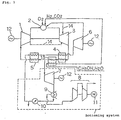
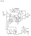
- Turbinenkraftwerk mit
einem Kompressor (1) zum Komprimieren eines Gasgemischs aus Dampf und Kohlendioxid als Arbeitsfluid,
einer Brennkammer (2) zum Verbrennen eines Brennstoffs zusammen mit dem mit Sauerstoff angereicherten Arbeitsfluid aus dem Kompressor (1),
einer Hochtemperaturturbine (3) zum Expandieren eines Verbrennungsgases aus der Brennkammer (2), um Arbeit bzw. Leistung zu erhalten,
einem Nachschaltsystem ("bottoming system") mit einem Wasserkondensiersystem,
einem Wärmetauscher (4,5) zum Erwärmen eines Kondenswassers aus dem Nachschaltsystem auf einen Hochtemperaturdampf durch Wärmetausch mit dem Abgas aus der Hochtemperaturturbine (3) und zum Leiten des Abgases nach seiner Nutzung für den Wärmetausch in einen Einlaß des Kompressors (1) als Arbeitsfluid, und
einer Hochdruckturbine (6) zum Expandieren des an dem Wärmetauscher (4,5) erwärmten Hochdruckdampfs des Nachschaltsystems, um Arbeit bzw. Leistung zu erhalten, und zum Mischen des so expandierten Dampfs in die Brennkammer (2),
dadurch gekennzeichnet, dass es ferner umfaßt
einen Reformer (13) zum Aufnehmen eines Gemischs von Methanol und Wasser, das durch am Wärmetauscher (4) aufgenommene Wärme in Wasserstoff und Kohlendioxid zu reformieren ist, und zum Zuführen des Wasserstoffs und Kohlendioxids in die Brennkammer (2) als Brennstoff, und
ein Hochtemperatur-Turbinenkühlsystem, welches das Arbeitsfluid aus einem Auslaß des Kompressors (1) und einem Auslaß der Hochdruckturbine (6) extrahiert, damit dieses als Kühlmedium in einen Hochtemperaturabschnitt der Hochtemperaturturbine (3) zu dessen Kühlung geleitet wird. - Turbinenkraftwerk mit
einem Kompressor (1) zum Komprimieren eines Gasgemischs aus Dampf und Kohlendioxid als Arbeitsfluid,
einer Brennkammer (2) zum Verbrennen eines fossilen Brennstoffs, der Methanol enthält, zusammen mit dem mit Sauerstoff angereicherten Arbeitsfluid von dem Kompressor (1),
einer Hochtemperaturturbine (3) zum Expandieren eines Verbrennungsgases von der Brennkammer (2), um Arbeit bzw. Leistung zu erhalten,
einem Nachschaltsystem ("bottoming system") zum Antreiben einer Niederdruckturbine (7) durch ein Abgas aus der Hochtemperaturturbine (3), um Arbeit bzw. Leistung zu erhalten,
einem Wärmetauscher (4,5) zum Erwärmen eines Kondenswassers aus dem Nachschaltsystem auf einen Hochtemperaturdampf durch Wärmetausch mit dem Abgas aus der Hochtemperaturturbine (3) und zum Leiten des Abgases nach dessen Nutzung für den Wärmetausch in einen Einlaß des Kompressors (1) als Arbeitsfluid, und
einer Hochdruckturbine (6) zum Expandieren des an dem Wärmetauscher (4,5) erwärmten Hochtemperaturdampfs des Nachschaltsystems, um Arbeit bzw. Leistung zu erhalten, und zum Mischen des so expandierten Dampfs in die Brennkammer (2),
dadurch gekennzeichnet, dass
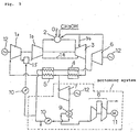
der Kompressor (1) einen Niederdruckkompressor (1a) und einen Hochdruckkompressor (1b) umfasst und so aufgebaut ist, dass zwischen dem Niederdruckkompressor (1a) und dem Hochdruckkompressor (1b) ein Durchgang zum Strömen lassen des Arbeitsfluids über einen Zwischenkühler (15) vorgesehen ist, und
ein Teil des Kondenswassers aus dem Nachschaltsystem unter Druck in den Zwischenkühler (15) gemischt wird,
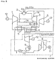
und ein Hochtemperatur-Turbinenkühlsystem vorgesehen ist, welches das Arbeitsfluid von einem Auslaß des Hochtemperaturkompressors (1b) und einem Auslaß der Hochdruckturbine (6) extrahiert, damit dieses als Kühlmedium in einen Hochtemperaturabschnitt der Hochtemperaturturbine (3) zu dessen Kühlung geleitet wird. - Turbinenkraftwerk mit
einem Kompressor (1) zum Komprimieren eines Gasgemischs aus Dampf und Kohlendioxid als Arbeitsfluid,
einer Brennkammer (2) zum Verbrennen eines fossilen Brennstoffs, der Methanol enthält, zusammen mit dem mit Sauerstoff angereicherten Arbeitsfluid von dem Kompressor (1) ,
einer Hochtemperaturturbine (3) zum Expandieren eines Verbrennungsgases von der Brennkammer (2), um Arbeit bzw. Leistung zu erhalten,
einem Nachschaltsystem ("bottoming system"), das ein Wasserkondensiersystem umfasst,
einem Wärmetauscher (4,5) zum Erwärmen eines Kondenswassers aus dem Nachschaltsystem auf einen Hochtemperaturdampf durch Wärmetausch mit dem Abgas aus der Hochtemperaturturbine (3) und zum Leiten des Abgases nach dessen Nutzung für den Wärmetausch in einen Einlaß des Kompressors (1) als Arbeitsfluid, und
einer Hochdruckturbine (6) zum Expandieren des an dem Wärmetauscher (4,5) erwärmten Hochtemperaturdampfs des Nachschaltsystems, um Arbeit bzw. Leistung zu erhalten, und zum Mischen des so expandierten Dampfs in die Brennkammer (2),
dadurch gekennzeichnet, dass
zwischen dem Auslaß des Kompressors (1) und einem Einlaß der Brennkammer (2) ein regenerativer Wärmetauscher (16) zum Anheben einer Einlassgastemperatur der Brennkammer (2) durch einen Wärmetausch zwischen einem Auslassgas des Kompressors (1) und dem Abgas aus der Hochtemperaturturbine (3) vorgesehen ist, und
ein Hochtemperatur-Turbinenkühlsystem vorgesehen ist, welches das Arbeitsfluid von einem Auslaß des Kompressors (1) und einem Auslaß der Hochdruckturbine (6) extrahiert, um es als Kühlmedium in einen Hochtemperaturabschnitt der Hochtemperaturturbine (3) zu deren Kühlung zu leiten. - Turbinenkraftwerk nach Anspruch 1, dadurch gekennzeichnet, dass zwischen dem Auslaß des Kompressors (1) und einem Einlaß der Brennkammer (2) ein regenerativer Wärmetaucher (16) zum Anheben einer Einlassgastemperatur der Brennkammer (2) durch einen Wärmetausch zwischen einem Auslassgas des Kompressors (1) und dem Abgas aus der Hochtemperaturturbine (3) vorgesehen ist.
- Turbinenkraftwerk nach Anspruch 1, 3 oder 4, dadurch gekennzeichnet, dass
das Nachschaltsystem nur das Wasserkondensiersystem umfasst und derart aufgebaut ist, dass das Kondenswasser aus dem Nachschaltsystem teilweise in den Einlaß des Kompressors (1) als Arbeitsfluid geleitet wird, und
das Abgas aus der Hochtemperaturturbine (3), nachdem es so am Wärmetauscher (4,5) einem Wärmetausch unterzogen wurde, in einen Kondensator (9) des Nachschaltsystems geleitet wird. - Turbinenkraftwerk nach Anspruch 1, 3 oder 4, dadurch gekennzeichnet, dass
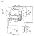
das Nachschaltsystem das Wasserkondensiersystem und einen CO2-Kompressor (8) umfasst und so aufgebaut ist, dass das Kondenswasser aus dem Nachschaltsystem teilweise als Arbeitsfluid in den Einlaß des Kompressors (1) geleitet wird, und
das Abgas aus der Hochtemperaturturbine (3), nachdem es so einem Wärmetausch am Wärmetauscher (4,5) unterzogen wurde, in einen Kondensator (9) des Nachschaltsystems geleitet wird. - Turbinenkraftwerk nach Anspruch 1, 3 oder 4, dadurch gekennzeichnet, dass das Nachschaltsystem eine Niederdruckturbine (7) umfasst, die von einem Abgas aus der Hochtemperaturturbine (3) angetrieben wird, um Arbeit bzw. Leistung zu erhalten.
Applications Claiming Priority (4)
| Application Number | Priority Date | Filing Date | Title |
|---|---|---|---|
| JP9466298 | 1998-04-07 | ||
| JP9466398A JPH11294114A (ja) | 1998-04-07 | 1998-04-07 | タービンプラント |
| JP9466398 | 1998-04-07 | ||
| JP9466298A JPH11294113A (ja) | 1998-04-07 | 1998-04-07 | タービンプラント |
Publications (3)
| Publication Number | Publication Date |
|---|---|
| EP0949405A2 EP0949405A2 (de) | 1999-10-13 |
| EP0949405A3 EP0949405A3 (de) | 2002-06-12 |
| EP0949405B1 true EP0949405B1 (de) | 2006-05-31 |
Family
ID=26435935
Family Applications (1)
| Application Number | Title | Priority Date | Filing Date |
|---|---|---|---|
| EP99106503A Expired - Lifetime EP0949405B1 (de) | 1998-04-07 | 1999-03-30 | Turbinenanlage |
Country Status (4)
| Country | Link |
|---|---|
| US (3) | US6260348B1 (de) |
| EP (1) | EP0949405B1 (de) |
| CA (1) | CA2267687C (de) |
| DE (1) | DE69931548T2 (de) |
Families Citing this family (64)
| Publication number | Priority date | Publication date | Assignee | Title |
|---|---|---|---|---|
| GB9817292D0 (en) * | 1998-08-07 | 1998-10-07 | Nokia Mobile Phones Ltd | Digital video coding |
| US6608395B1 (en) * | 2000-03-28 | 2003-08-19 | Kinder Morgan, Inc. | Hybrid combined cycle power generation facility |
| CA2409700C (en) * | 2000-05-12 | 2010-02-09 | Clean Energy Systems, Inc. | Semi-closed brayton cycle gas turbine power systems |
| US6921595B2 (en) | 2000-05-31 | 2005-07-26 | Nuvera Fuel Cells, Inc. | Joint-cycle high-efficiency fuel cell system with power generating turbine |
| US6817182B2 (en) | 2001-12-05 | 2004-11-16 | Lawrence G. Clawson | High-efficiency Otto cycle engine with power generating expander |
| US6916564B2 (en) * | 2000-05-31 | 2005-07-12 | Nuvera Fuel Cells, Inc. | High-efficiency fuel cell power system with power generating expander |
| US6651421B2 (en) * | 2000-10-02 | 2003-11-25 | Richard R. Coleman | Coleman regenerative engine with exhaust gas water extraction |
| ATE343048T1 (de) * | 2002-03-14 | 2006-11-15 | Alstom Technology Ltd | Wärmekraftprozess |
| US6532745B1 (en) * | 2002-04-10 | 2003-03-18 | David L. Neary | Partially-open gas turbine cycle providing high thermal efficiencies and ultra-low emissions |
| US7178339B2 (en) * | 2004-04-07 | 2007-02-20 | Lockheed Martin Corporation | Closed-loop cooling system for a hydrogen/oxygen based combustor |
| WO2005100754A2 (en) | 2004-04-16 | 2005-10-27 | Clean Energy Systems, Inc. | Zero emissions closed rankine cycle power system |
| WO2006083296A2 (en) * | 2004-06-11 | 2006-08-10 | Nuvera Fuel Cells, Inc. | Fuel fired hydrogen generator |
| US7093446B2 (en) * | 2004-09-15 | 2006-08-22 | General Electric Company | Gas turbine engine having improved core system |
| US7096674B2 (en) * | 2004-09-15 | 2006-08-29 | General Electric Company | High thrust gas turbine engine with improved core system |
| US20060149423A1 (en) * | 2004-11-10 | 2006-07-06 | Barnicki Scott D | Method for satisfying variable power demand |
| US20070006566A1 (en) * | 2005-07-05 | 2007-01-11 | General Electric Company | Syngas turbine |
| US7266940B2 (en) * | 2005-07-08 | 2007-09-11 | General Electric Company | Systems and methods for power generation with carbon dioxide isolation |
| US7726114B2 (en) * | 2005-12-07 | 2010-06-01 | General Electric Company | Integrated combustor-heat exchanger and systems for power generation using the same |
| US7634915B2 (en) * | 2005-12-13 | 2009-12-22 | General Electric Company | Systems and methods for power generation and hydrogen production with carbon dioxide isolation |
| EP1808588A1 (de) * | 2006-01-14 | 2007-07-18 | Thermal PowerTec GmbH | Leistungs- und Wirkungsgradsteigerung in Gasturbinen- und Kombi-Anlagen |
| WO2007098239A2 (en) * | 2006-02-21 | 2007-08-30 | Clean Energy Systems, Inc. | Hybrid oxy-fuel combustion power process |
| US20080314018A1 (en) * | 2007-06-08 | 2008-12-25 | Subhash Chander | Operation of internal combustion (IC) engines and gas turbines with concurrently generated oxygen enriched air |
| US8806849B2 (en) * | 2008-07-30 | 2014-08-19 | The University Of Wyoming | System and method of operating a power generation system with an alternative working fluid |
| US20100024378A1 (en) * | 2008-07-30 | 2010-02-04 | John Frederick Ackermann | System and method of operating a gas turbine engine with an alternative working fluid |
| US8534073B2 (en) * | 2008-10-27 | 2013-09-17 | General Electric Company | System and method for heating a fuel using an exhaust gas recirculation system |
| AU2010205940A1 (en) * | 2009-01-15 | 2011-09-01 | Martin Hadlauer | Coupled gas/steam turbine |
| CH700310A1 (de) * | 2009-01-23 | 2010-07-30 | Alstom Technology Ltd | Verfahren zur CO2 Abscheidung aus einem Kombikraftwerk und Kombikraftwerk mit einer Gasturbine mit Strömungsteilung und Rezirkulation. |
| US8596075B2 (en) | 2009-02-26 | 2013-12-03 | Palmer Labs, Llc | System and method for high efficiency power generation using a carbon dioxide circulating working fluid |
| US10018115B2 (en) | 2009-02-26 | 2018-07-10 | 8 Rivers Capital, Llc | System and method for high efficiency power generation using a carbon dioxide circulating working fluid |
| EA024852B1 (ru) | 2009-02-26 | 2016-10-31 | Палмер Лэбз, Ллк | Способ и устройство для сжигания топлива при высокой температуре и высоком давлении и соответствующие система и средства |
| US20120067054A1 (en) | 2010-09-21 | 2012-03-22 | Palmer Labs, Llc | High efficiency power production methods, assemblies, and systems |
| US8869889B2 (en) | 2010-09-21 | 2014-10-28 | Palmer Labs, Llc | Method of using carbon dioxide in recovery of formation deposits |
| US9410481B2 (en) * | 2010-09-21 | 2016-08-09 | 8 Rivers Capital, Llc | System and method for high efficiency power generation using a nitrogen gas working fluid |
| CN102080600B (zh) * | 2010-12-01 | 2013-07-17 | 株洲南方燃气轮机成套制造安装有限公司 | 一种应用化工驰放气发电的系统及方法 |
| US20120159924A1 (en) * | 2010-12-23 | 2012-06-28 | General Electric Company | System and method for increasing efficiency and water recovery of a combined cycle power plant |
| TWI564474B (zh) * | 2011-03-22 | 2017-01-01 | 艾克頌美孚上游研究公司 | 於渦輪系統中控制化學計量燃燒的整合系統和使用彼之產生動力的方法 |
| US9604892B2 (en) | 2011-08-04 | 2017-03-28 | Stephen L. Cunningham | Plasma ARC furnace with supercritical CO2 heat recovery |
| US20130036723A1 (en) * | 2011-08-08 | 2013-02-14 | Air Liquide Process And Construction Inc. | Oxy-combustion gas turbine hybrid |
| CN104160130B (zh) | 2011-11-02 | 2017-08-25 | 八河流资产有限责任公司 | 发电系统和相应方法 |
| US9540999B2 (en) | 2012-01-17 | 2017-01-10 | Peregrine Turbine Technologies, Llc | System and method for generating power using a supercritical fluid |
| US8776532B2 (en) | 2012-02-11 | 2014-07-15 | Palmer Labs, Llc | Partial oxidation reaction with closed cycle quench |
| US20150000298A1 (en) * | 2013-03-15 | 2015-01-01 | Advanced Green Technologies, Llc | Fuel conditioner, combustor and gas turbine improvements |
| WO2014146861A1 (en) * | 2013-03-21 | 2014-09-25 | Siemens Aktiengesellschaft | Power generation system and method to operate |
| JP6220586B2 (ja) * | 2013-07-22 | 2017-10-25 | 8 リバーズ キャピタル,エルエルシー | ガスタービン設備 |
| JP6250332B2 (ja) | 2013-08-27 | 2017-12-20 | 8 リバーズ キャピタル,エルエルシー | ガスタービン設備 |
| US9657599B2 (en) | 2014-02-26 | 2017-05-23 | Peregrine Turbine Technologies, Llc | Power generation system and method with partially recuperated flow path |
| EP3140601A4 (de) | 2014-05-09 | 2017-11-08 | Stephen Lee Cunningham | Lichtbogenofenschmelzsystem und verfahren |
| TWI657195B (zh) | 2014-07-08 | 2019-04-21 | 美商八河資本有限公司 | 加熱再循環氣體流的方法、生成功率的方法及功率產出系統 |
| BR112017003614B1 (pt) | 2014-08-22 | 2021-08-17 | Peregrine Turbine Technologies, Llc | Trocador de calor configurado para um sistema de geração de energia |
| US11231224B2 (en) | 2014-09-09 | 2022-01-25 | 8 Rivers Capital, Llc | Production of low pressure liquid carbon dioxide from a power production system and method |
| EA033135B1 (ru) | 2014-09-09 | 2019-08-30 | 8 Риверз Кэпитл, Ллк | Способ получения жидкого диоксида углерода под низким давлением из системы генерации мощности |
| US10961920B2 (en) | 2018-10-02 | 2021-03-30 | 8 Rivers Capital, Llc | Control systems and methods suitable for use with power production systems and methods |
| MA40950A (fr) | 2014-11-12 | 2017-09-19 | 8 Rivers Capital Llc | Systèmes et procédés de commande appropriés pour une utilisation avec des systèmes et des procédés de production d'énergie |
| US11686258B2 (en) | 2014-11-12 | 2023-06-27 | 8 Rivers Capital, Llc | Control systems and methods suitable for use with power production systems and methods |
| CA2989618A1 (en) | 2015-06-15 | 2016-12-22 | 8 Rivers Capital, Llc | System and method for startup of a power production plant |
| CN105258384B (zh) * | 2015-11-26 | 2017-12-19 | 中国科学院工程热物理研究所 | 一种集成热化学过程的热电冷多联产系统 |
| JP6960930B2 (ja) | 2016-02-18 | 2021-11-05 | 8 リバーズ キャピタル,エルエルシー | メタン生成を含む電力生産のためのシステムおよび方法 |
| EA038390B1 (ru) | 2016-02-26 | 2021-08-20 | 8 Риверз Кэпитл, Ллк | Система и способ управления энергетической установкой |
| EP3512925B1 (de) | 2016-09-13 | 2022-03-30 | 8 Rivers Capital, LLC | System und verfahren zur energieerzeugung mit partieller oxidation |
| ES2960368T3 (es) | 2017-08-28 | 2024-03-04 | 8 Rivers Capital Llc | Optimización de calor de baja calidad de ciclos de energía recuperativa de CO2 supercrítico |
| US10914232B2 (en) | 2018-03-02 | 2021-02-09 | 8 Rivers Capital, Llc | Systems and methods for power production using a carbon dioxide working fluid |
| DE102021122631A1 (de) * | 2021-09-01 | 2023-03-02 | Obrist Technologies Gmbh | Antriebssystem für ein Fahrzeug |
| US11828200B2 (en) * | 2022-02-11 | 2023-11-28 | Raytheon Technologies Corporation | Hydrogen-oxygen fueled powerplant with water and heat recovery |
| CN114776411B (zh) * | 2022-05-27 | 2023-05-05 | 华能国际电力股份有限公司 | 一种集成储热的燃煤发电系统及工作方法 |
Family Cites Families (12)
| Publication number | Priority date | Publication date | Assignee | Title |
|---|---|---|---|---|
| US5175995A (en) * | 1989-10-25 | 1993-01-05 | Pyong-Sik Pak | Power generation plant and power generation method without emission of carbon dioxide |
| US5669216A (en) * | 1990-02-01 | 1997-09-23 | Mannesmann Aktiengesellschaft | Process and device for generating mechanical energy |
| JPH04191418A (ja) * | 1990-11-26 | 1992-07-09 | Mitsubishi Heavy Ind Ltd | Co↓2回収発電プラント |
| JP3454372B2 (ja) | 1994-02-04 | 2003-10-06 | 石川島播磨重工業株式会社 | クローズドサイクルガスタービンの燃焼方法及び装置 |
| JP2680782B2 (ja) * | 1994-05-24 | 1997-11-19 | 三菱重工業株式会社 | 燃料改質器を組み合せた石炭焚きコンバインド発電プラント |
| US5782081A (en) * | 1994-05-31 | 1998-07-21 | Pyong Sik Pak | Hydrogen-oxygen burning turbine plant |
| JP3196549B2 (ja) | 1995-01-09 | 2001-08-06 | 株式会社日立製作所 | 燃料改質装置を備えた発電システム |
| US5595059A (en) * | 1995-03-02 | 1997-01-21 | Westingthouse Electric Corporation | Combined cycle power plant with thermochemical recuperation and flue gas recirculation |
| JP2880938B2 (ja) | 1995-11-24 | 1999-04-12 | 株式会社東芝 | 水素燃焼ガスタービンプラント |
| SE510738C2 (sv) * | 1996-05-20 | 1999-06-21 | Nonox Eng Ab | Sätt samt anordning för elgenerering på basis av förbränning av gasformiga bränslen |
| DE69729038T2 (de) * | 1996-09-20 | 2005-05-12 | Kabushiki Kaisha Toshiba, Kawasaki | Kraftwerk mit Trennung und Rückgewinnung von Kohlenstoffdioxid |
| US5809768A (en) * | 1997-04-08 | 1998-09-22 | Mitsubishi Heavy Industries, Ltd. | Hydrogen-oxygen combustion turbine plant |
-
1999
- 1999-03-30 EP EP99106503A patent/EP0949405B1/de not_active Expired - Lifetime
- 1999-03-30 DE DE69931548T patent/DE69931548T2/de not_active Expired - Lifetime
- 1999-03-31 CA CA002267687A patent/CA2267687C/en not_active Expired - Fee Related
- 1999-04-02 US US09/285,066 patent/US6260348B1/en not_active Expired - Fee Related
-
2001
- 2001-05-30 US US09/866,710 patent/US6430916B2/en not_active Expired - Lifetime
-
2002
- 2002-03-14 US US10/096,939 patent/US6536205B2/en not_active Expired - Fee Related
Also Published As
| Publication number | Publication date |
|---|---|
| CA2267687C (en) | 2002-02-12 |
| EP0949405A3 (de) | 2002-06-12 |
| US20010023580A1 (en) | 2001-09-27 |
| US20020095931A1 (en) | 2002-07-25 |
| US6430916B2 (en) | 2002-08-13 |
| CA2267687A1 (en) | 1999-10-07 |
| EP0949405A2 (de) | 1999-10-13 |
| US6536205B2 (en) | 2003-03-25 |
| US6260348B1 (en) | 2001-07-17 |
| DE69931548T2 (de) | 2007-05-10 |
| DE69931548D1 (de) | 2006-07-06 |
Similar Documents
| Publication | Publication Date | Title |
|---|---|---|
| EP0949405B1 (de) | Turbinenanlage | |
| EP1580483B1 (de) | Dampfturbinenanlage | |
| US7703271B2 (en) | Cogeneration method and device using a gas turbine comprising a post-combustion chamber | |
| CN1043390C (zh) | 联合产生电能及机械能的方法及装置 | |
| EP0622535B1 (de) | Gebrauch von Stickstoff von einer Luftzerlegungsanlage um die Zufuhrluft zum Kompressor einer Gasturbine zu kühlen und dadurch der Wirkungsgrad zu erhöhen | |
| CN101622425B (zh) | 在整体气化联合循环系统中分离氧气的系统和方法 | |
| US6868677B2 (en) | Combined fuel cell and fuel combustion power generation systems | |
| US7421835B2 (en) | Air-staged reheat power generation system | |
| US5669216A (en) | Process and device for generating mechanical energy | |
| WO2001095409A3 (en) | Joint-cycle high-efficiency fuel cell system with power generating turbine | |
| JPH1068329A (ja) | 合成ガスおよびエネルギーを組み合わせて製造する方法 | |
| CN1869418A (zh) | 一种燃气动力循环系统及循环方法 | |
| US5349810A (en) | Humid air turbine (HAT) cycle power process | |
| EP1091095B1 (de) | Gasturbinensystem und Kombianlage mit einer solchen Gasturbine | |
| US20080141645A1 (en) | System and method for low emissions combustion | |
| CN101566103A (zh) | 一种以氢为燃料的动力循环方法 | |
| WO2021121762A1 (en) | Energy conversion system | |
| JPH11294114A (ja) | タービンプラント | |
| JPH11294113A (ja) | タービンプラント | |
| Campanari et al. | The integration of atmospheric molten carbonate fuel cells with gas turbine and steam cycles | |
| JPH06318464A (ja) | 燃料電池/ガスタービン複合発電システムの運転方法 | |
| JP2005097023A (ja) | 水素生産システム |
Legal Events
| Date | Code | Title | Description |
|---|---|---|---|
| PUAI | Public reference made under article 153(3) epc to a published international application that has entered the european phase |
Free format text: ORIGINAL CODE: 0009012 |
|
| 17P | Request for examination filed |
Effective date: 19990427 |
|
| AK | Designated contracting states |
Kind code of ref document: A2 Designated state(s): AT BE CH CY DE DK ES FI FR GB GR IE IT LI LU MC NL PT SE |
|
| AX | Request for extension of the european patent |
Free format text: AL;LT;LV;MK;RO;SI |
|
| PUAL | Search report despatched |
Free format text: ORIGINAL CODE: 0009013 |
|
| AK | Designated contracting states |
Kind code of ref document: A3 Designated state(s): AT BE CH CY DE DK ES FI FR GB GR IE IT LI LU MC NL PT SE |
|
| AX | Request for extension of the european patent |
Free format text: AL;LT;LV;MK;RO;SI |
|
| AKX | Designation fees paid |
Designated state(s): CH DE FR GB IT LI |
|
| 17Q | First examination report despatched |
Effective date: 20040415 |
|
| GRAP | Despatch of communication of intention to grant a patent |
Free format text: ORIGINAL CODE: EPIDOSNIGR1 |
|
| GRAS | Grant fee paid |
Free format text: ORIGINAL CODE: EPIDOSNIGR3 |
|
| GRAA | (expected) grant |
Free format text: ORIGINAL CODE: 0009210 |
|
| AK | Designated contracting states |
Kind code of ref document: B1 Designated state(s): CH DE FR GB IT LI |
|
| PG25 | Lapsed in a contracting state [announced via postgrant information from national office to epo] |
Ref country code: LI Free format text: LAPSE BECAUSE OF FAILURE TO SUBMIT A TRANSLATION OF THE DESCRIPTION OR TO PAY THE FEE WITHIN THE PRESCRIBED TIME-LIMIT Effective date: 20060531 Ref country code: IT Free format text: LAPSE BECAUSE OF FAILURE TO SUBMIT A TRANSLATION OF THE DESCRIPTION OR TO PAY THE FEE WITHIN THE PRESCRIBED TIME-LIMIT;WARNING: LAPSES OF ITALIAN PATENTS WITH EFFECTIVE DATE BEFORE 2007 MAY HAVE OCCURRED AT ANY TIME BEFORE 2007. THE CORRECT EFFECTIVE DATE MAY BE DIFFERENT FROM THE ONE RECORDED. Effective date: 20060531 Ref country code: CH Free format text: LAPSE BECAUSE OF FAILURE TO SUBMIT A TRANSLATION OF THE DESCRIPTION OR TO PAY THE FEE WITHIN THE PRESCRIBED TIME-LIMIT Effective date: 20060531 |
|
| REG | Reference to a national code |
Ref country code: GB Ref legal event code: FG4D Ref country code: CH Ref legal event code: EP |
|
| REF | Corresponds to: |
Ref document number: 69931548 Country of ref document: DE Date of ref document: 20060706 Kind code of ref document: P |
|
| REG | Reference to a national code |
Ref country code: CH Ref legal event code: PL |
|
| PLBE | No opposition filed within time limit |
Free format text: ORIGINAL CODE: 0009261 |
|
| STAA | Information on the status of an ep patent application or granted ep patent |
Free format text: STATUS: NO OPPOSITION FILED WITHIN TIME LIMIT |
|
| EN | Fr: translation not filed | ||
| 26N | No opposition filed |
Effective date: 20070301 |
|
| GBPC | Gb: european patent ceased through non-payment of renewal fee |
Effective date: 20070330 |
|
| PG25 | Lapsed in a contracting state [announced via postgrant information from national office to epo] |
Ref country code: GB Free format text: LAPSE BECAUSE OF NON-PAYMENT OF DUE FEES Effective date: 20070330 Ref country code: FR Free format text: LAPSE BECAUSE OF FAILURE TO SUBMIT A TRANSLATION OF THE DESCRIPTION OR TO PAY THE FEE WITHIN THE PRESCRIBED TIME-LIMIT Effective date: 20070309 |
|
| PG25 | Lapsed in a contracting state [announced via postgrant information from national office to epo] |
Ref country code: FR Free format text: LAPSE BECAUSE OF FAILURE TO SUBMIT A TRANSLATION OF THE DESCRIPTION OR TO PAY THE FEE WITHIN THE PRESCRIBED TIME-LIMIT Effective date: 20060531 |
|
| PGFP | Annual fee paid to national office [announced via postgrant information from national office to epo] |
Ref country code: DE Payment date: 20130327 Year of fee payment: 15 |
|
| REG | Reference to a national code |
Ref country code: DE Ref legal event code: R119 Ref document number: 69931548 Country of ref document: DE |
|
| REG | Reference to a national code |
Ref country code: DE Ref legal event code: R119 Ref document number: 69931548 Country of ref document: DE Effective date: 20141001 |
|
| PG25 | Lapsed in a contracting state [announced via postgrant information from national office to epo] |
Ref country code: DE Free format text: LAPSE BECAUSE OF NON-PAYMENT OF DUE FEES Effective date: 20141001 |