EP4048487B1 - Mechanisches armgelenk - Google Patents
Mechanisches armgelenk Download PDFInfo
- Publication number
- EP4048487B1 EP4048487B1 EP20811253.2A EP20811253A EP4048487B1 EP 4048487 B1 EP4048487 B1 EP 4048487B1 EP 20811253 A EP20811253 A EP 20811253A EP 4048487 B1 EP4048487 B1 EP 4048487B1
- Authority
- EP
- European Patent Office
- Prior art keywords
- speed side
- assembly
- motor
- fixed
- low
- Prior art date
- Legal status (The legal status is an assumption and is not a legal conclusion. Google has not performed a legal analysis and makes no representation as to the accuracy of the status listed.)
- Active
Links
Images
Classifications
-
- B—PERFORMING OPERATIONS; TRANSPORTING
- B25—HAND TOOLS; PORTABLE POWER-DRIVEN TOOLS; MANIPULATORS
- B25J—MANIPULATORS; CHAMBERS PROVIDED WITH MANIPULATION DEVICES
- B25J9/00—Program-controlled manipulators
- B25J9/10—Program-controlled manipulators characterised by positioning means for manipulator elements
- B25J9/102—Gears specially adapted therefor, e.g. reduction gears
- B25J9/1025—Harmonic drives
-
- B—PERFORMING OPERATIONS; TRANSPORTING
- B25—HAND TOOLS; PORTABLE POWER-DRIVEN TOOLS; MANIPULATORS
- B25J—MANIPULATORS; CHAMBERS PROVIDED WITH MANIPULATION DEVICES
- B25J13/00—Controls for manipulators
- B25J13/08—Controls for manipulators by means of sensing devices, e.g. viewing or touching devices
- B25J13/085—Force or torque sensors
-
- B—PERFORMING OPERATIONS; TRANSPORTING
- B25—HAND TOOLS; PORTABLE POWER-DRIVEN TOOLS; MANIPULATORS
- B25J—MANIPULATORS; CHAMBERS PROVIDED WITH MANIPULATION DEVICES
- B25J17/00—Joints
Definitions
- the invention relates to the field of mechanical arm, in particular to a mechanical arm joint.
- a torque sensor is arranged on an output side of a joint generally, such as Chinese patent CN207548790U which discloses a driving device and a robot, and Chinese application CN109715348A which discloses a driving unit of a manipulator.
- the torque sensor is extremely sensitive to impacts, and thus when the torque sensor is exposed on the joint, the torque sensor is easy to be damaged during assembling and maintaining; and the power cables and signal cables of the torque sensor are connected to the circuit board on the right end of the joint through the joint center hole; the torque sensor cables need to pass through the joint center hole, therefore the joint center hole must be large; and further, long cables are not beneficial to signal transmission and the signal transmitted in the long cables will interfere with signals in other cables in the joint central hole.
- the power cables and signal cables are connected to the circuit board at the right end of the joint from the side of the joint instead of through the joint center hole, so that the torque sensor cable and other cables in the joint are arranged separately, therefore the signal of the torque sensor does not interfere with the signal in other cables, and it is beneficial to the torque sensor signal transmission due to the length of cable is shorter, and the joint structure is more compact because of the diameter of joint center hole becomes smaller due to the number of the cables passed through the joint center hole decreases.
- a mechanical arm joint comprising a hollow shaft and a brake assembly, a motor assembly, a harmonic reducer assembly, an output assembly, a housing assembly, and a measurement assembly which are disposed outside the hollow shaft, and the measurement assembly includes a torque sensor, and the torque sensor is provided inside the housing assembly and fixed to the housing assembly, the torque sensor is fixed to the harmonic reducer assembly at the same time.
- the motor assembly includes a motor housing, a motor shaft, an input shaft, a motor stator, and a motor rotor, the motor stator is fixed to the motor housing, the motor rotor is fixed to the motor shaft, and the motor shaft is fixed to the input shaft.
- the output assembly comprises an output flange, an output end housing, and a roller bearing, and the roller bearing is disposed between the output flange and the output end housing.
- roller bearing is a cross roller bearing.
- the harmonic reducer assembly comprises a wave generator, a flexible wheel, and a rigid wheel.
- the wave generator is fixed to an input shaft of the motor assembly, the flexible wheel is fixed to the torque sensor, and the rigid wheel is fixed to an output flange of the output assembly.
- the flexible wheel is fixed to the torque sensor through a flexible wheel mounting plate.
- a friction structure member is provided between the flexible wheel mounting plate and the torque sensor.
- the measuring assembly further includes a high-speed side encoder and a low-speed side encoder, the high-speed side encoder is used to measure the speed of the motor, and the low-speed side encoder is used to measure the position of the output flange.
- the high-speed side encoder includes a high-speed side reading head and a high-speed side magnetic ring, the position of the high-speed side reading head is constant in relation to the housing assembly, and the high-speed side magnetic ring moves synchronously with the motor shaft.
- the high-speed side encoder further includes a high-speed side reading head bracket, the high-speed side reading head bracket is fixed to the housing assembly, the high-speed side reading head bracket is fixed to the high-speed side reading head.
- the low-speed side encoder includes a low-speed side reading head and a low-speed side magnetic ring, the position of the low-speed side reading head is constant in relation to the housing assembly, the position of the output flange of the output assembly is constant in relation to the hollow shaft and the low-speed side magnetic ring, the output flange of the output assembly can drive the hollow shaft and the low-speed side magnetic ring to move synchronously.
- the low-speed side encoder further includes a low-speed side reading head bracket and a hoop, the low-speed side magnetic ring and the hoop are fixed to the low-speed side reading head bracket respectively; and the hoop is fixed to the hollow shaft.
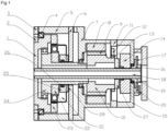
- Figure 1 is a sectional view of a mechanical arm joint.
- the above drawing includes the following reference signs: 1 - output flange; 2 - bearing inner ring pressing plate; 3- bearing outer ring pressing plate; 4-cross roller bearing; 5- output end housing; 6- torque sensor; 7- motor housing; 8- motor stator; 9- motor rotor ;10- motor shaft ;11- high-speed side reading head bracket; 12-high-speed side reading head; 13- high-speed side magnetic ring; 14- brake; 15- brake housing; 16- low-speed side reading head bracket; 17- low-speed side magnetic ring; 18-hollow shaft; 19- hoop;20- low-speed side reading head;21- flexible wheel; 22- wave generator; 23- rigid wheel;24- input shaft;25- flexible wheel mounting plate;26- seal ring ;27- rotor hub ;28- friction structure member.
- a mechanical arm joint includes a hollow shaft 18 and a brake assembly, a motor assembly, a harmonic reducer assembly, an output assembly, a housing assembly, and a measurement assembly.
- the brake assembly, motor assembly, harmonic reducer assembly, output assembly, housing assembly, and measurement assembly are disposed outside the hollow shaft 18.
- the measurement assembly includes a torque sensor 6, and the torque sensor 6 is provided inside the housing assembly and fixed to the housing assembly, the torque sensor 6 is fixed to the harmonic reducer assembly at the same time, preferably by screw.
- the housing assembly includes an output end housing 5, a motor housing 7, and a brake housing 15.
- the positions of the output end housing 5, the motor housing 7, and the brake housing 15 are fixed relative to the others.
- the housing assembly have various structural forms and connection forms.
- the housing assembly can be divided into several parts along the axial direction, the cross-sections of the several parts contacts and are fixed together by screws, or the several parts connected together by circumferential nesting. Or, the housing assembly can be divided into several parts along the circumferential direction, and then the several parts are fixed together.
- the other assembly (brake assembly, a motor assembly, a harmonic reducer assembly, an output assembly, and a measurement assembly) are arranged in the housing assembly through fixed connection or bearing support.
- the motor assembly includes the motor housing 7, a motor shaft 10, an input shaft 24, a motor stator 8; and a motor rotor 9, the motor stator 8 is fixed to the motor housing 7, the motor rotor 9 is fixed to the motor shaft 10, preferably by gluing. And the motor shaft 10 is fixed to the input shaft 24, preferably by screw. Both ends of the motor shaft 10 and the input shaft 24 are supported in the housing assembly through bearings.
- the motor is a frameless motor, so the motor has a compact structure due to the motor is glued to the motor housing 7 and the motor shaft 10.
- the output assembly includes an output flange 1, the output end housing 5, and a cross roller bearing 4.
- the cross roller bearing 4 is provided between the output flange 1 and the output end housing 5.
- the output flange 1 is supported by the cross roller bearing 4 so that the output flange 1 can withstand forces in all directions.
- the output flange 1 of the output assembly is fixed to one end of the hollow shaft 18, preferably by gluing, the other end of the hollow shaft 18 is supported in the brake housing 15 through a bearing.
- the output assembly further includes a bearing inner ring pressing plate 2 and a bearing outer ring pressing plate 3, the output flange 1 is fixed to the bearing inner ring pressing plate 2, the bearing outer ring pressing plate 3 is fixed to the output end housing 5, preferably by screw; and the inner ring of the cross roller bearing 4 is pressed against the bearing inner ring pressing plate 2 tightly by pressure therebetween, the outer ring of the cross roller bearing 4 is pressed against the bearing outer ring pressing plate 3 tightly by pressure therebetween.
- the harmonic reducer assembly includes a wave generator 22, a flexible wheel 21 and a rigid wheel 23.
- the wave generator 22 is fixed to the input shaft 24 of the motor assembly.
- the input shaft 24 passes through the central circular hole of the flexible wheel 21, the flexible wheel 21 is fixed to the torque sensor 6, and the rigid wheel 23 is fixed to the output flange 1 of the output assembly. that is, the torque is input by the wave generator 22, the torque is output by the rigid wheel 23, so that the torque is increased by decreasing the speed.
- the torque sensor 6 measures torque forced on the joint by detecting the torque forced on the flexible wheel 21.
- the flexible wheel 21 is fixed to the torque sensor 6 through a flexible wheel mounting plate 25.
- a seal ring 26 is provided between the flexible wheel mounting plate 25 and the input shaft 24.
- a friction structure member 28 is provided between the flexible wheel 21 and the torque sensor 6, and the mating surface of the flexible wheel 21 and the mating surface of the torque sensor 6 are simultaneously pressed against the friction structure member 28 tightly by pressure therebetween.
- the joint motor is provided on the side of flexible wheel 21 of the harmonic reducer assembly, the motor shaft is connected to the input shaft 24, and the input shaft 24 passes through the central circular hole of the flexible wheel 21 and connects to the wave generator 22. And the flexible wheel 21 is fixed to the motor housing 7, the rigid wheel 23 of the harmonic reducer assembly is used as an output.
- the torque sensor 6 is provided in the joint to ensure that the torque sensor is not damaged by external impacts during assembling and maintaining of the joint and the mechanical arm; and further, the power cables and signal cables are connected to the circuit board at the right end of the joint from the side of the joint instead of through the center hole of the joint, so that the torque sensor cable and other cables in the joint are arranged separately, therefore the signal of the torque sensor does not interfere with the signal in other cables, and it is conducive to the torque sensor signal transmission due to the length of cable is shorter, and the joint structure is more compact because of the diameter of joint center hole becomes smaller due to the number of the cables passed through the joint center hole decreases.
- the power cable and signal cable of the torque sensor 6 are connected to the circuit board at the right end of the joint from outside the joint so that the center hole is not occupied by the power cable and signal cable of the torque sensor 6, and the power cable and signal cable of the torque sensor 6 and other power cables and signal cables in the joint are arranged separately so that the signal of the torque sensor does not interfere with the signal in other cables each other.
- the torque sensor 6 is connected to the output end housing 5 and the motor housing 7 by screw. It can be understood that the torque sensor 6 is connected to the housing assembly in various ways, for example, the torque sensor 6 is separately fixed to the output end housing 5 or the motor housing. 7. The torque sensor is fixed on the motor housing 7, so the torque sensor will not rotate in relation to the motor housing during operation.
- the brake assembly includes a brake 14, a brake housing 15, and a rotor hub 27.
- the brake 14 is fixed to the brake housing 15, preferably by screw.
- the rotor hub 27 is fixed to the motor shaft 10.
- the shape of the rotor hub 27 is square, and the rotor hub is matched with the square hole in the center of the brake to achieve the braking function.
- the brake assembly keeps the joint in the current position after power off, and provides braking during emergency stop, so the joint is safe and reliable.
- the measuring assembly further includes a high-speed side encoder and a low-speed side encoder.
- the high-speed side encoder is used to measure the speed of the motor, that is, the speed of the joint
- the low-speed side encoder is used to measure the position of the output flange, that is, the position of the joint.
- the high-speed side encoder includes a high-speed side reading head 12 and a high-speed side magnetic ring 13.
- the position of the high-speed side reading head 12 is constant in relation to the housing assembly, and the high-speed side magnetic ring 13 moves synchronously with the motor shaft 10.
- the motor shaft 10 drives the high-speed side magnetic ring 13 to rotate, and the high-speed side reading head 12 reads the high-speed side magnetic ring 13 to obtain the speed of the motor.
- the high-speed side encoder further includes a high-speed side reading head bracket 11, the high-speed side reading head bracket 11 is fixed to the high-speed side reading head 12, and the high-speed side reading head bracket 11 is fixed to the motor housing 7 and/or the brake housing 15, preferably by screw.
- the low-speed side encoder includes a low-speed side reading head 20 and a low-speed side magnetic ring 17.
- the position of the low-speed side reading head 20 is constant in relation to the housing assembly, the output flange 1 of the output assembly can drive the hollow shaft 18 and the low-speed side magnetic ring 17 to move synchronously.
- the low-speed side reading head 20 reads the low-speed side magnetic ring 17 to obtain the position of the output flange 1, that is, the position of the joint.
- the low-speed side reading head 20 is fixed to the brake housing 15, preferably by screw.
- the low-speed side encoder further includes a low-speed side reading head bracket 16 and a hoop 19, the low-speed side magnetic ring 17 and the hoop 19 are fixed to the low-speed side reading head bracket 16 respectively; and the hoop 19 is fixed to the hollow shaft, preferably by screw, and a bearing is provided between the low-speed side reading head bracket 16 and the brake housing 15.
- the brake 14 is opened, and the motor rotor 9 rotates under the electromagnetic action.
- the motor rotor 9 drives the motor shaft 10, the input shaft 24 which passes through the center hole of the flexible wheel 21 and the wave generator 22 to rotate, and a harmonic reducer assembly comprises the flexible wheel 21,
- the wave generator 22 and the rigid wheel 23 drives the wave generator 22 to rotate as an input, and the flexible wheel 21 is fixed, the rigid wheel 23 drives output flange 1 to rotate as an output, so the torque is increased and the speed is reduced.
- the torque sensor 6 does not rotate in relation to the motor housing 7 during this process.
- the output flange 1 can withstand forces in various directions under the support of the cross roller bearing 4.
- the torque sensor 6 measures torque forced on the output flange 1, that is, the torque forced on the flexible wheel 21, by detecting the torque forced on the flexible wheel 21.
- the high-speed side encoder comprises the high-speed side reading head 12 and the high-speed side magnetic ring 13, the motor shaft 10 drives the high-speed side magnetic ring 13 to rotate.
- the high-speed side reading head 12 reads the high-speed side magnetic ring 13 to obtain the speed of the motor.
- the low-speed side encoder comprises the low-speed side reading head 20 and the low-speed side magnetic ring 17,
- the output flange 1 drives the hollow shaft 18 and the low-speed side magnetic ring 17 to rotate, the low-speed side reading head 20 reads the low-speed side magnetic ring 17 to obtain the position of the output flange 1, that is, the position of the joint.
Landscapes
- Engineering & Computer Science (AREA)
- Robotics (AREA)
- Mechanical Engineering (AREA)
- Human Computer Interaction (AREA)
- Manipulator (AREA)
- Seal Device For Vehicle (AREA)
- Surgical Instruments (AREA)
- Glass Compositions (AREA)
- Connection Of Motors, Electrical Generators, Mechanical Devices, And The Like (AREA)
Claims (10)
- Mechanisches Armgelenk, bestehend aus einer Hohlwelle (18) und einer Bremsbaugruppe, einer Motorbaugruppe, einer harmonischen Untersetzungsbaugruppe, einer Ausgangsbaugruppe, einer Gehäusebaugruppe und einer Messbaugruppe, die außerhalb der Hohlwelle (18) angeordnet sind, wobeidie Messbaugruppe einen Drehmomentsensor (6) umfasst, und der Drehmomentsensor (6) innerhalb der Gehäusebaugruppe vorgesehen und an der Gehäusebaugruppe befestigt ist, wobei der Drehmomentsensor (6) gleichzeitig an der harmonischen Untersetzungsbaugruppe befestigt ist;und wobei die Oberwellenreduzieranordnung einen Wellengenerator (22), ein flexibles Rad (21) und ein starres Rad (23) umfasst, wobei das flexible Rad (21) an dem Drehmomentsensor (6) durch eine flexible Radbefestigungsplatte (25) befestigt ist, wobei das mechanische Armgelenk ferner ein Reibungsstrukturelement umfasst,dadurch gekennzeichnet, dassdas Reibungsstrukturelement (28) zwischen der flexiblen Radbefestigungsplatte (25) und dem Drehmomentsensor (6) vorgesehen ist, wobei das flexible Rad (21) und der Drehmomentsensor (6) so angeordnet sind, dass eine Gegenfläche des flexiblen Rades (21) und eine Gegenfläche des Drehmomentsensors (6) gleichzeitig gegen das Reibungsstrukturelement (28) gedrückt werden.
- Mechanisches Armgelenk nach Anspruch 1, dadurch gekennzeichnet, dass die Motorbaugruppe ein Motorgehäuse (7), eine Motorwelle (10), eine Eingangswelle (24), einen Motorstator (8) und einen Motorrotor (9) umfasst, wobei der Motorstator (8) an dem Motorgehäuse (7), der Motorrotor (9) an der Motorwelle (10) und die Motorwelle (10) an der Eingangswelle (24) befestigt ist.
- Mechanisches Armgelenk nach Anspruch 1, dadurch gekennzeichnet, dass die Abtriebsbaugruppe einen Abtriebsflansch (1), ein abtriebsseitiges Gehäuse (5) und ein Wälzlager umfasst, wobei das Wälzlager zwischen dem Abtriebsflansch (1) und dem abtriebsseitigen Gehäuse (5) angeordnet ist.
- Mechanisches Armgelenk nach Anspruch 3, dadurch gekennzeichnet, dass das Rollenlager ein Kreuzrollenlager (4) ist.
- Mechanisches Armgelenk nach Anspruch 1, dadurch gekennzeichnet, dass der Wellengenerator (22) an einer Eingangswelle (24) der Motorbaugruppe befestigt ist, das flexible Rad (21) am Drehmomentsensor (6) befestigt ist und das starre Rad (23) an einem Ausgangsflansch (1) der Ausgangsbaugruppe befestigt ist.
- Mechanisches Armgelenk nach Anspruch 1, dadurch gekennzeichnet, dass die Messanordnung ferner einen Hochgeschwindigkeits-Seitengeber und einen Niedergeschwindigkeits-Seitengeber umfasst, wobei der Hochgeschwindigkeits-Seitengeber zur Messung der Geschwindigkeit des Motors und der Niedergeschwindigkeits-Seitengeber zur Messung der Position des Ausgangsflansches verwendet wird.
- Mechanisches Armgelenk nach Anspruch 6, dadurch gekennzeichnet, dass der Hochgeschwindigkeits-Seitencodierer einen Hochgeschwindigkeits-Seitenlesekopf (12) und einen Hochgeschwindigkeits-Seitenmagnetring (13) umfasst, die Position des Hochgeschwindigkeits-Seitenlesekopfes (12) in Bezug auf die Gehäusebaugruppe konstant ist und der Hochgeschwindigkeits-Seitenmagnetring (13) sich synchron mit der Motorwelle (10) bewegt.
- Mechanisches Armgelenk nach Anspruch 7, dadurch gekennzeichnet, dass der Hochgeschwindigkeits-Seitencodierer ferner eine Hochgeschwindigkeits-Seitenlesekopf-Halterung (11) umfasst, wobei die Hochgeschwindigkeits-Seitenlesekopf-Halterung (11) an der Gehäusebaugruppe befestigt ist und die Hochgeschwindigkeits-Seitenlesekopf-Halterung (11) an dem Hochgeschwindigkeits-Seitenlesekopf (12) befestigt ist.
- Mechanisches Armgelenk nach Anspruch 6, dadurch gekennzeichnet, dass der niedertourige Seitencodierer einen niedertourigen Seitenlesekopf (20) und einen niedertourigen Seitenmagnetring (17) umfasst, die Position des niedertourigen Seitenlesekopfes (20) in Bezug auf die Gehäusebaugruppe konstant ist, die Position des Abtriebsflansches (1) der Abtriebsbaugruppe in Bezug auf die Hohlwelle (18) und den niedertourigen Seitenmagnetring (17) konstant ist, der Abtriebsflansch (1) der Abtriebsbaugruppe die Hohlwelle (18) und den niedertourigen Seitenmagnetring (17) antreiben kann, um sich synchron zu bewegen.
- Mechanisches Armgelenk nach Anspruch 9, dadurch gekennzeichnet, dass der langsame Seitencodierer ferner eine langsame Seitenlesekopfhalterung (16) und einen Ring (19) umfasst, wobei der langsame Seitenmagnetring (17) und der Ring (19) jeweils an der langsamen Seitenlesekopfhalterung (16) befestigt sind; und der Ring (19) an der Hohlwelle (18) befestigt ist.
Applications Claiming Priority (2)
| Application Number | Priority Date | Filing Date | Title |
|---|---|---|---|
| CN201911208252.2A CN110919688B (zh) | 2019-11-30 | 2019-11-30 | 一种机械臂关节 |
| PCT/EP2020/082431 WO2021104948A1 (en) | 2019-11-30 | 2020-11-17 | Mechanical arm joint |
Publications (3)
| Publication Number | Publication Date |
|---|---|
| EP4048487A1 EP4048487A1 (de) | 2022-08-31 |
| EP4048487C0 EP4048487C0 (de) | 2024-10-02 |
| EP4048487B1 true EP4048487B1 (de) | 2024-10-02 |
Family
ID=69847108
Family Applications (1)
| Application Number | Title | Priority Date | Filing Date |
|---|---|---|---|
| EP20811253.2A Active EP4048487B1 (de) | 2019-11-30 | 2020-11-17 | Mechanisches armgelenk |
Country Status (6)
| Country | Link |
|---|---|
| US (1) | US12246445B2 (de) |
| EP (1) | EP4048487B1 (de) |
| JP (1) | JP7402338B2 (de) |
| KR (1) | KR20220125238A (de) |
| CN (1) | CN110919688B (de) |
| WO (1) | WO2021104948A1 (de) |
Families Citing this family (17)
| Publication number | Priority date | Publication date | Assignee | Title |
|---|---|---|---|---|
| WO2022041005A1 (en) * | 2020-08-26 | 2022-03-03 | Rethink Robotics Gmbh | Transmission device, robotic joint, and robot |
| CN111993455B (zh) * | 2020-09-14 | 2024-11-26 | 苏州因时机器人科技有限公司 | 一种电动夹爪 |
| CN114603600B (zh) * | 2020-12-08 | 2023-08-08 | 山东新松工业软件研究院股份有限公司 | 一种机器人关节的装配方法 |
| CN112743567B (zh) * | 2020-12-28 | 2022-05-17 | 深圳市优必选科技股份有限公司 | 舵机模组及机器人 |
| CN112744303A (zh) * | 2021-02-03 | 2021-05-04 | 深圳亿嘉和科技研发有限公司 | 一种关节式履带机器人 |
| CN115674254A (zh) * | 2021-07-21 | 2023-02-03 | 中强光电股份有限公司 | 机器人的关节致动器 |
| CN115237186B (zh) * | 2021-08-13 | 2025-01-14 | 中国科学院宁波材料技术与工程研究所 | 旋转驱动装置 |
| CN113715014B (zh) * | 2021-09-22 | 2023-11-21 | 哈尔滨工业大学 | 适用于深海机器人的大力矩一体化驱动关节 |
| CN113977625A (zh) * | 2021-11-16 | 2022-01-28 | 上海微电机研究所(中国电子科技集团公司第二十一研究所) | 一种集成双减速器控制于一体的电动关节模组 |
| CN116172708A (zh) * | 2021-11-29 | 2023-05-30 | 深圳康诺思腾科技有限公司 | 用于手术机器人的器械驱动器和手术机器人 |
| CN116252326A (zh) * | 2021-12-10 | 2023-06-13 | 中光电智能感测股份有限公司 | 机器人的关节致动器 |
| CN114505885A (zh) * | 2022-03-04 | 2022-05-17 | 北京思灵机器人科技有限责任公司 | 模块化并联弹性驱动器 |
| CN114523482B (zh) * | 2022-03-14 | 2024-03-29 | 哈尔滨工业大学 | 一种轻质防瞬时冲击的按压式操作工具存储平台 |
| CN114714393A (zh) * | 2022-05-13 | 2022-07-08 | 上海节卡机器人科技有限公司 | 一种一体化关节 |
| CN115284267B (zh) * | 2022-10-08 | 2023-03-03 | 深圳市越疆科技有限公司 | 协作机械臂及其关节模组 |
| CN117532595B (zh) * | 2023-12-27 | 2024-07-19 | 广东灵锶智能科技有限公司 | 一种谐波减速关节模组及机器人 |
| CN120886302B (zh) * | 2025-10-09 | 2025-12-02 | 江苏开璇智能科技有限公司 | 一种智能力控关节模组 |
Citations (2)
| Publication number | Priority date | Publication date | Assignee | Title |
|---|---|---|---|---|
| US5155423A (en) * | 1986-02-18 | 1992-10-13 | Robotics Research Corporation | Industrial robot with servo |
| US20190271361A1 (en) * | 2016-12-15 | 2019-09-05 | Boston Dynamics, Inc. | Transmission with Integrated Overload Protection for a Legged Robot |
Family Cites Families (21)
| Publication number | Priority date | Publication date | Assignee | Title |
|---|---|---|---|---|
| DE10317304A1 (de) | 2002-04-12 | 2003-12-11 | Deutsch Zentr Luft & Raumfahrt | Verfahren und Einrichtung zum Bestimmen eines Abtriebsdrehmoments eines Elektromotors |
| CN101209556A (zh) * | 2006-12-30 | 2008-07-02 | 浙江工业大学 | 一种机器人灵巧手臂关节驱动及其减速装置 |
| WO2010142318A1 (en) | 2009-06-08 | 2010-12-16 | Abb Technology Ab | A device for measuring torque |
| CN101913151B (zh) * | 2010-08-26 | 2011-08-17 | 哈尔滨工业大学 | 大型空间服务机器人在轨可更换关节 |
| CN105313132A (zh) * | 2014-07-29 | 2016-02-10 | 北京自动化控制设备研究所 | 一种高集成度机器人关节 |
| CN104552329B (zh) * | 2014-12-23 | 2016-04-27 | 哈尔滨工业大学深圳研究生院 | 驱动控制一体化智能集成关节 |
| WO2017012626A1 (en) * | 2015-07-21 | 2017-01-26 | Kr 2013 Aps | Joint assembly |
| DE102016004810B3 (de) | 2016-04-20 | 2017-06-14 | Sami Haddadin | Antriebsvorrichtung für einen Manipulator |
| KR101793141B1 (ko) * | 2016-06-10 | 2017-11-03 | 한국기계연구원 | 관절구동모듈과 순응형 로봇의족 |
| CN106737825B (zh) * | 2016-12-30 | 2019-02-12 | 哈尔滨工业大学 | 一种适用于机械臂的抗冲击柔性关节 |
| JP6824764B2 (ja) * | 2017-01-27 | 2021-02-03 | キヤノン株式会社 | センサ、ロボット装置及び物品の製造方法 |
| CN107650141A (zh) * | 2017-03-02 | 2018-02-02 | 北京军立方机器人科技有限公司 | 一种机械臂关节 |
| CN206899266U (zh) * | 2017-07-12 | 2018-01-19 | 北京军立方机器人科技有限公司 | 一种机械臂关节 |
| CN107685341A (zh) * | 2017-08-10 | 2018-02-13 | 北京山思跃立科技有限公司 | 一种机械臂和机械臂关节 |
| CN108247668A (zh) * | 2018-02-06 | 2018-07-06 | 北京精密机电控制设备研究所 | 一种集成化的机器人关节模组 |
| CN108297127B (zh) * | 2018-02-27 | 2021-01-29 | 哈尔滨工业大学 | 一种基于弹性元件的可变刚度被动柔顺关节 |
| DE102018204338A1 (de) * | 2018-03-21 | 2019-09-26 | Kuka Deutschland Gmbh | Drehgelenkanordnung |
| CN108381598A (zh) * | 2018-03-28 | 2018-08-10 | 中国科学院宁波材料技术与工程研究所 | 一种机器人智能驱动关节和机器人 |
| CN208896129U (zh) * | 2018-08-30 | 2019-05-24 | 深圳市智能机器人研究院 | 智能化机器人驱动关节 |
| CN109366480A (zh) | 2018-12-19 | 2019-02-22 | 浙江双环传动机械股份有限公司 | 一种高集成度机电控一体化机器人关节模组 |
| CN110171016A (zh) | 2019-05-22 | 2019-08-27 | 西安电子科技大学 | 一种基于高速串行通信的完全模块化柔性关节 |
-
2019
- 2019-11-30 CN CN201911208252.2A patent/CN110919688B/zh active Active
-
2020
- 2020-11-17 KR KR1020227022342A patent/KR20220125238A/ko not_active Ceased
- 2020-11-17 JP JP2022532576A patent/JP7402338B2/ja active Active
- 2020-11-17 US US17/780,606 patent/US12246445B2/en active Active
- 2020-11-17 EP EP20811253.2A patent/EP4048487B1/de active Active
- 2020-11-17 WO PCT/EP2020/082431 patent/WO2021104948A1/en not_active Ceased
Patent Citations (2)
| Publication number | Priority date | Publication date | Assignee | Title |
|---|---|---|---|---|
| US5155423A (en) * | 1986-02-18 | 1992-10-13 | Robotics Research Corporation | Industrial robot with servo |
| US20190271361A1 (en) * | 2016-12-15 | 2019-09-05 | Boston Dynamics, Inc. | Transmission with Integrated Overload Protection for a Legged Robot |
Also Published As
| Publication number | Publication date |
|---|---|
| EP4048487C0 (de) | 2024-10-02 |
| CN110919688A (zh) | 2020-03-27 |
| US12246445B2 (en) | 2025-03-11 |
| WO2021104948A1 (en) | 2021-06-03 |
| EP4048487A1 (de) | 2022-08-31 |
| CN110919688B (zh) | 2021-07-16 |
| JP7402338B2 (ja) | 2023-12-20 |
| JP2023511000A (ja) | 2023-03-16 |
| US20230356416A1 (en) | 2023-11-09 |
| KR20220125238A (ko) | 2022-09-14 |
Similar Documents
| Publication | Publication Date | Title |
|---|---|---|
| EP4048487B1 (de) | Mechanisches armgelenk | |
| KR102808870B1 (ko) | 액추에이터 장치 및 이를 구비하는 로봇 관절 | |
| CN106826906A (zh) | 一种无力矩传感器的机械臂模块化关节 | |
| CN106918756A (zh) | 导电滑环专用跑合测试装置 | |
| CN111140636B (zh) | 一种摆动式太阳帆板驱动机构 | |
| CN212909273U (zh) | 一种用于伺服直驱螺旋压力机的角度检测反馈装置 | |
| CN201909691U (zh) | 一种连续旋转轴扭矩检测装置 | |
| CN111452083B (zh) | 一种具有力/位检测的一体化关节式驱控模块 | |
| CN211362329U (zh) | 一种机械臂关节 | |
| CN218412583U (zh) | 一种机械隔离式双余度液压测速旋变传感器 | |
| CN115480072B (zh) | 一种机械隔离式双余度液压测速旋变传感器 | |
| CN208663856U (zh) | 一种机械臂关节和机械臂 | |
| CN219726285U (zh) | 一种关节电机执行器结构 | |
| CN215811633U (zh) | 一种轴承单元振动测试装置 | |
| CN100359190C (zh) | 一种内置式液压油缸位移传感器 | |
| CN222450343U (zh) | 机械臂的关节模组、机械臂及机器人 | |
| CN114714393A (zh) | 一种一体化关节 | |
| CN219977628U (zh) | 一种燃油泵的扭矩传感器 | |
| CN222802699U (zh) | 一种内置式电机扭矩传感器及电机 | |
| CN223192451U (zh) | 一种联轴器用动态扭矩传感器 | |
| CN210265554U (zh) | 一种套筒式编码器小轴连接组件 | |
| CN223477672U (zh) | 一种一体化关节及机械臂 | |
| CN223109839U (zh) | 用于伺服电机的转轴监测编码器机构 | |
| CN217020453U (zh) | 一种双编码器协作机器人关节和工业机器人 | |
| CN118934848B (zh) | 一种可抗高过载的光电载荷轴系结构 |
Legal Events
| Date | Code | Title | Description |
|---|---|---|---|
| STAA | Information on the status of an ep patent application or granted ep patent |
Free format text: STATUS: UNKNOWN |
|
| STAA | Information on the status of an ep patent application or granted ep patent |
Free format text: STATUS: THE INTERNATIONAL PUBLICATION HAS BEEN MADE |
|
| PUAI | Public reference made under article 153(3) epc to a published international application that has entered the european phase |
Free format text: ORIGINAL CODE: 0009012 |
|
| STAA | Information on the status of an ep patent application or granted ep patent |
Free format text: STATUS: REQUEST FOR EXAMINATION WAS MADE |
|
| 17P | Request for examination filed |
Effective date: 20220526 |
|
| AK | Designated contracting states |
Kind code of ref document: A1 Designated state(s): AL AT BE BG CH CY CZ DE DK EE ES FI FR GB GR HR HU IE IS IT LI LT LU LV MC MK MT NL NO PL PT RO RS SE SI SK SM TR |
|
| DAV | Request for validation of the european patent (deleted) | ||
| DAX | Request for extension of the european patent (deleted) | ||
| GRAP | Despatch of communication of intention to grant a patent |
Free format text: ORIGINAL CODE: EPIDOSNIGR1 |
|
| STAA | Information on the status of an ep patent application or granted ep patent |
Free format text: STATUS: GRANT OF PATENT IS INTENDED |
|
| INTG | Intention to grant announced |
Effective date: 20240529 |
|
| GRAS | Grant fee paid |
Free format text: ORIGINAL CODE: EPIDOSNIGR3 |
|
| GRAA | (expected) grant |
Free format text: ORIGINAL CODE: 0009210 |
|
| STAA | Information on the status of an ep patent application or granted ep patent |
Free format text: STATUS: THE PATENT HAS BEEN GRANTED |
|
| RAP3 | Party data changed (applicant data changed or rights of an application transferred) |
Owner name: BEIJING SILING ROBOT TECHNOLOGY CO., LTD. Owner name: AGILE ROBOTS SE |
|
| AK | Designated contracting states |
Kind code of ref document: B1 Designated state(s): AL AT BE BG CH CY CZ DE DK EE ES FI FR GB GR HR HU IE IS IT LI LT LU LV MC MK MT NL NO PL PT RO RS SE SI SK SM TR |
|
| REG | Reference to a national code |
Ref country code: GB Ref legal event code: FG4D |
|
| REG | Reference to a national code |
Ref country code: CH Ref legal event code: EP |
|
| REG | Reference to a national code |
Ref country code: IE Ref legal event code: FG4D |
|
| REG | Reference to a national code |
Ref country code: DE Ref legal event code: R096 Ref document number: 602020038772 Country of ref document: DE |
|
| U01 | Request for unitary effect filed |
Effective date: 20241015 |
|
| RAP4 | Party data changed (patent owner data changed or rights of a patent transferred) |
Owner name: BEIJING SILING ROBOT TECHNOLOGY CO., LTD. Owner name: AGILE ROBOTS SE |
|
| U07 | Unitary effect registered |
Designated state(s): AT BE BG DE DK EE FI FR IT LT LU LV MT NL PT RO SE SI Effective date: 20241108 |
|
| U20 | Renewal fee for the european patent with unitary effect paid |
Year of fee payment: 5 Effective date: 20241218 |
|
| PG25 | Lapsed in a contracting state [announced via postgrant information from national office to epo] |
Ref country code: IS Free format text: LAPSE BECAUSE OF FAILURE TO SUBMIT A TRANSLATION OF THE DESCRIPTION OR TO PAY THE FEE WITHIN THE PRESCRIBED TIME-LIMIT Effective date: 20250202 Ref country code: HR Free format text: LAPSE BECAUSE OF FAILURE TO SUBMIT A TRANSLATION OF THE DESCRIPTION OR TO PAY THE FEE WITHIN THE PRESCRIBED TIME-LIMIT Effective date: 20241002 |
|
| PG25 | Lapsed in a contracting state [announced via postgrant information from national office to epo] |
Ref country code: ES Free format text: LAPSE BECAUSE OF FAILURE TO SUBMIT A TRANSLATION OF THE DESCRIPTION OR TO PAY THE FEE WITHIN THE PRESCRIBED TIME-LIMIT Effective date: 20241002 |
|
| PG25 | Lapsed in a contracting state [announced via postgrant information from national office to epo] |
Ref country code: NO Free format text: LAPSE BECAUSE OF FAILURE TO SUBMIT A TRANSLATION OF THE DESCRIPTION OR TO PAY THE FEE WITHIN THE PRESCRIBED TIME-LIMIT Effective date: 20250102 |
|
| PG25 | Lapsed in a contracting state [announced via postgrant information from national office to epo] |
Ref country code: GR Free format text: LAPSE BECAUSE OF FAILURE TO SUBMIT A TRANSLATION OF THE DESCRIPTION OR TO PAY THE FEE WITHIN THE PRESCRIBED TIME-LIMIT Effective date: 20250103 |
|
| PG25 | Lapsed in a contracting state [announced via postgrant information from national office to epo] |
Ref country code: PL Free format text: LAPSE BECAUSE OF FAILURE TO SUBMIT A TRANSLATION OF THE DESCRIPTION OR TO PAY THE FEE WITHIN THE PRESCRIBED TIME-LIMIT Effective date: 20241002 Ref country code: CZ Free format text: LAPSE BECAUSE OF FAILURE TO SUBMIT A TRANSLATION OF THE DESCRIPTION OR TO PAY THE FEE WITHIN THE PRESCRIBED TIME-LIMIT Effective date: 20241002 |
|
| PG25 | Lapsed in a contracting state [announced via postgrant information from national office to epo] |
Ref country code: RS Free format text: LAPSE BECAUSE OF FAILURE TO SUBMIT A TRANSLATION OF THE DESCRIPTION OR TO PAY THE FEE WITHIN THE PRESCRIBED TIME-LIMIT Effective date: 20250102 |
|
| PG25 | Lapsed in a contracting state [announced via postgrant information from national office to epo] |
Ref country code: SM Free format text: LAPSE BECAUSE OF FAILURE TO SUBMIT A TRANSLATION OF THE DESCRIPTION OR TO PAY THE FEE WITHIN THE PRESCRIBED TIME-LIMIT Effective date: 20241002 |
|
| PG25 | Lapsed in a contracting state [announced via postgrant information from national office to epo] |
Ref country code: MC Free format text: LAPSE BECAUSE OF FAILURE TO SUBMIT A TRANSLATION OF THE DESCRIPTION OR TO PAY THE FEE WITHIN THE PRESCRIBED TIME-LIMIT Effective date: 20241002 |
|
| PG25 | Lapsed in a contracting state [announced via postgrant information from national office to epo] |
Ref country code: SK Free format text: LAPSE BECAUSE OF FAILURE TO SUBMIT A TRANSLATION OF THE DESCRIPTION OR TO PAY THE FEE WITHIN THE PRESCRIBED TIME-LIMIT Effective date: 20241002 |
|
| PLBE | No opposition filed within time limit |
Free format text: ORIGINAL CODE: 0009261 |
|
| STAA | Information on the status of an ep patent application or granted ep patent |
Free format text: STATUS: NO OPPOSITION FILED WITHIN TIME LIMIT |
|
| 26N | No opposition filed |
Effective date: 20250703 |
|
| PG25 | Lapsed in a contracting state [announced via postgrant information from national office to epo] |
Ref country code: IE Free format text: LAPSE BECAUSE OF NON-PAYMENT OF DUE FEES Effective date: 20241117 |
|
| REG | Reference to a national code |
Ref country code: CH Ref legal event code: U11 Free format text: ST27 STATUS EVENT CODE: U-0-0-U10-U11 (AS PROVIDED BY THE NATIONAL OFFICE) Effective date: 20251201 |
|
| U20 | Renewal fee for the european patent with unitary effect paid |
Year of fee payment: 6 Effective date: 20251117 |
|
| PGFP | Annual fee paid to national office [announced via postgrant information from national office to epo] |
Ref country code: GB Payment date: 20251120 Year of fee payment: 6 |
|
| PGFP | Annual fee paid to national office [announced via postgrant information from national office to epo] |
Ref country code: CH Payment date: 20251201 Year of fee payment: 6 |
|
| PG25 | Lapsed in a contracting state [announced via postgrant information from national office to epo] |
Ref country code: HU Free format text: LAPSE BECAUSE OF FAILURE TO SUBMIT A TRANSLATION OF THE DESCRIPTION OR TO PAY THE FEE WITHIN THE PRESCRIBED TIME-LIMIT; INVALID AB INITIO Effective date: 20201117 |