EP4047850B1 - Transmission method, apparatus, first communication node, second communication node, and medium - Google Patents
Transmission method, apparatus, first communication node, second communication node, and medium Download PDFInfo
- Publication number
- EP4047850B1 EP4047850B1 EP20876828.3A EP20876828A EP4047850B1 EP 4047850 B1 EP4047850 B1 EP 4047850B1 EP 20876828 A EP20876828 A EP 20876828A EP 4047850 B1 EP4047850 B1 EP 4047850B1
- Authority
- EP
- European Patent Office
- Prior art keywords
- slot
- srs
- communication node
- sending
- resource set
- Prior art date
- Legal status (The legal status is an assumption and is not a legal conclusion. Google has not performed a legal analysis and makes no representation as to the accuracy of the status listed.)
- Active
Links
Images


Classifications
-
- H—ELECTRICITY
- H04—ELECTRIC COMMUNICATION TECHNIQUE
- H04W—WIRELESS COMMUNICATION NETWORKS
- H04W72/00—Local resource management
- H04W72/12—Wireless traffic scheduling
- H04W72/1263—Mapping of traffic onto schedule, e.g. scheduled allocation or multiplexing of flows
- H04W72/1273—Mapping of traffic onto schedule, e.g. scheduled allocation or multiplexing of flows of downlink data flows
-
- H—ELECTRICITY
- H04—ELECTRIC COMMUNICATION TECHNIQUE
- H04W—WIRELESS COMMUNICATION NETWORKS
- H04W72/00—Local resource management
- H04W72/20—Control channels or signalling for resource management
-
- H—ELECTRICITY
- H04—ELECTRIC COMMUNICATION TECHNIQUE
- H04L—TRANSMISSION OF DIGITAL INFORMATION, e.g. TELEGRAPHIC COMMUNICATION
- H04L5/00—Arrangements affording multiple use of the transmission path
- H04L5/003—Arrangements for allocating sub-channels of the transmission path
- H04L5/0048—Allocation of pilot signals, i.e. of signals known to the receiver
-
- H—ELECTRICITY
- H04—ELECTRIC COMMUNICATION TECHNIQUE
- H04L—TRANSMISSION OF DIGITAL INFORMATION, e.g. TELEGRAPHIC COMMUNICATION
- H04L27/00—Modulated-carrier systems
- H04L27/26—Systems using multi-frequency codes
- H04L27/2601—Multicarrier modulation systems
- H04L27/2602—Signal structure
- H04L27/26025—Numerology, i.e. varying one or more of symbol duration, subcarrier spacing, Fourier transform size, sampling rate or down-clocking
-
- H—ELECTRICITY
- H04—ELECTRIC COMMUNICATION TECHNIQUE
- H04L—TRANSMISSION OF DIGITAL INFORMATION, e.g. TELEGRAPHIC COMMUNICATION
- H04L27/00—Modulated-carrier systems
- H04L27/26—Systems using multi-frequency codes
- H04L27/2601—Multicarrier modulation systems
- H04L27/2602—Signal structure
- H04L27/261—Details of reference signals
- H04L27/2613—Structure of the reference signals
-
- H—ELECTRICITY
- H04—ELECTRIC COMMUNICATION TECHNIQUE
- H04L—TRANSMISSION OF DIGITAL INFORMATION, e.g. TELEGRAPHIC COMMUNICATION
- H04L5/00—Arrangements affording multiple use of the transmission path
- H04L5/0001—Arrangements for dividing the transmission path
- H04L5/0003—Two-dimensional division
-
- H—ELECTRICITY
- H04—ELECTRIC COMMUNICATION TECHNIQUE
- H04L—TRANSMISSION OF DIGITAL INFORMATION, e.g. TELEGRAPHIC COMMUNICATION
- H04L5/00—Arrangements affording multiple use of the transmission path
- H04L5/003—Arrangements for allocating sub-channels of the transmission path
- H04L5/0048—Allocation of pilot signals, i.e. of signals known to the receiver
- H04L5/0051—Allocation of pilot signals, i.e. of signals known to the receiver of dedicated pilots, i.e. pilots destined for a single user or terminal
-
- H—ELECTRICITY
- H04—ELECTRIC COMMUNICATION TECHNIQUE
- H04L—TRANSMISSION OF DIGITAL INFORMATION, e.g. TELEGRAPHIC COMMUNICATION
- H04L5/00—Arrangements affording multiple use of the transmission path
- H04L5/003—Arrangements for allocating sub-channels of the transmission path
- H04L5/0053—Allocation of signalling, i.e. of overhead other than pilot signals
-
- H—ELECTRICITY
- H04—ELECTRIC COMMUNICATION TECHNIQUE
- H04L—TRANSMISSION OF DIGITAL INFORMATION, e.g. TELEGRAPHIC COMMUNICATION
- H04L5/00—Arrangements affording multiple use of the transmission path
- H04L5/003—Arrangements for allocating sub-channels of the transmission path
- H04L5/0078—Timing of allocation
-
- H—ELECTRICITY
- H04—ELECTRIC COMMUNICATION TECHNIQUE
- H04L—TRANSMISSION OF DIGITAL INFORMATION, e.g. TELEGRAPHIC COMMUNICATION
- H04L5/00—Arrangements affording multiple use of the transmission path
- H04L5/0091—Signalling for the administration of the divided path, e.g. signalling of configuration information
- H04L5/0094—Indication of how sub-channels of the path are allocated
-
- H—ELECTRICITY
- H04—ELECTRIC COMMUNICATION TECHNIQUE
- H04W—WIRELESS COMMUNICATION NETWORKS
- H04W72/00—Local resource management
- H04W72/04—Wireless resource allocation
- H04W72/044—Wireless resource allocation based on the type of the allocated resource
- H04W72/0446—Resources in time domain, e.g. slots or frames
-
- H—ELECTRICITY
- H04—ELECTRIC COMMUNICATION TECHNIQUE
- H04W—WIRELESS COMMUNICATION NETWORKS
- H04W72/00—Local resource management
- H04W72/04—Wireless resource allocation
- H04W72/044—Wireless resource allocation based on the type of the allocated resource
- H04W72/0453—Resources in frequency domain, e.g. a carrier in FDMA
-
- H—ELECTRICITY
- H04—ELECTRIC COMMUNICATION TECHNIQUE
- H04W—WIRELESS COMMUNICATION NETWORKS
- H04W72/00—Local resource management
- H04W72/20—Control channels or signalling for resource management
- H04W72/23—Control channels or signalling for resource management in the downlink direction of a wireless link, i.e. towards a terminal
- H04W72/231—Control channels or signalling for resource management in the downlink direction of a wireless link, i.e. towards a terminal the control data signalling from the layers above the physical layer, e.g. RRC or MAC-CE signalling
-
- H—ELECTRICITY
- H04—ELECTRIC COMMUNICATION TECHNIQUE
- H04W—WIRELESS COMMUNICATION NETWORKS
- H04W72/00—Local resource management
- H04W72/20—Control channels or signalling for resource management
- H04W72/23—Control channels or signalling for resource management in the downlink direction of a wireless link, i.e. towards a terminal
- H04W72/232—Control channels or signalling for resource management in the downlink direction of a wireless link, i.e. towards a terminal the control data signalling from the physical layer, e.g. DCI signalling
-
- H—ELECTRICITY
- H04—ELECTRIC COMMUNICATION TECHNIQUE
- H04L—TRANSMISSION OF DIGITAL INFORMATION, e.g. TELEGRAPHIC COMMUNICATION
- H04L5/00—Arrangements affording multiple use of the transmission path
- H04L5/0001—Arrangements for dividing the transmission path
- H04L5/0014—Three-dimensional division
- H04L5/0023—Time-frequency-space
Definitions
- the present application relates to radio communication networks, for example, a transmission method and apparatus, a first communication node, a second communication node, and a medium.
- a first communication node can determine the channel state information of a second communication node according to an uplink signal, for example, a sounding reference signal (SRS) or a physical uplink shared channel (PUSCH) signal, sent by the second communication node. On this basis, the first communication node performs operations including frequency-domain selective scheduling and closed-loop power control. Additionally, the first communication node may also send a downlink signal, for example, a channel state information-reference signal (CSI-RS) or a physical downlink shared channel (PDSCH), to the second communication node so that the second communication node receives, processes, or measures the downlink signal.
- CSI-RS channel state information-reference signal
- PDSCH physical downlink shared channel
- the second communication node may be configured with multiple antenna groups, and uplink signals or downlink signals may be transmitted through different uplink or downlink slots.
- the flexibility of signal transmission between the first communication node and the second communication node is poor, failing to guarantee a valid and accurate signal transmission in any situation, even leading to a signal sending link being inconsistent with a signal receiving link, and thus affecting the reliability of communication.
- 3GPP Draft R1-1910289, 3GPP Draft R1-1910946 and CN 110 324 124 A are related prior art documents.
- the invention is specified by the independent claims. Preferred embodiments are defined in the dependent claims. In the following description, although numerous features may be designated as optional, it is nevertheless acknowledged that all features comprised in the independent claims are not to be read as optional.
- the present application provides a transmission method and apparatus, a first communication node, a second communication node, and a medium so as to improve the flexibility of signal transmission and the reliability of communication.
- a physical downlink control channel (PDCCH) is used for carrying downlink control information (DCI) that may include uplink scheduling information, downlink scheduling information, and uplink power control information.
- DCI formats include DCI formats 0, 1, 1A, 1B, 1C, 1D, 2, 2A, 3, 3A, etc; and DCI formats 2B, 2C, and 2D are later added to evolved LTE-ARelease 12 to support a variety of different applications and transmission modes.
- a first communication node can configure a device of a second communication node through the DCI.
- the first communication node may be an evolved base station (e-Node-B or eNB), and the second communication node may be a user equipment (UE).
- the device of the second communication node may accept the configuration through higher layers; that is, the second communication node is configured through higher-layer signaling.
- a sounding reference signal is a signal used between the second communication node and the first communication node for measuring channel state information (CSI).
- the second communication node periodically sends an uplink SRS on the last data symbol of a sending subframe according to parameters, indicated by the first communication node, such as a frequency band, a frequency domain position, a sequence cyclic shift, a period, and a subframe offset.
- the first communication node determines the uplink CSI of the second communication node according to the received SRS, and performs operations such as frequency domain selection scheduling and closed loop power control according to the obtained CSI.
- a non-precoded SRS that is, an antenna-specific SRS
- DMRS demodulation reference signal
- the first communication node may estimate original uplink CSI by receiving the non-precoded SRS, while may not estimate the original uplink CSI through the precoded DMRS.
- the second communication node sends the non-precoded SRS by using multiple antennas, more SRS resources are required by each second communication node, which results in a decrease in the number of second communication nodes that can be simultaneously reused in a radio communication system.
- the second communication node may be triggered, through the higher-layer signaling (also referred to as trigger type 0) or the DCI (also referred to as trigger type 1), to send the SRS.
- a periodic SRS is triggered based on the higher-layer signaling, and a non-periodic SRS is triggered based on the DCI.
- a manner of sending the non-periodic SRS is added, which improves the utilization rate of SRS resources to some extent and improves the flexibility of resource scheduling.
- high-frequency (30 to 300 GHz) carrier communication which has not been fully utilized has become an important communication way of achieving high-speed data communication in the future.
- the high-frequency carrier communication has a large available bandwidth and can provide a valid high-speed data communication.
- a big technical challenge for the high-frequency carrier communication is that high-frequency signals fade significantly in space compared with low-frequency signals. Although this will cause spatial fading losses when the high-frequency signals are used for outdoor communication, the shorter wavelength of the high-frequency signals usually allows using more antennas. Therefore, the communication is implemented based on beams to compensate for the spatial fading losses.
- the second communication node may be configured with multiple antenna groups, and uplink signals or downlink signals may be transmitted through different uplink or downlink slots.
- the flexibility of signal transmission between the first communication node and the second communication node is poor, failing to guarantee a valid and accurate signal transmission in any situation, even leading to a signal sending link being inconsistent with a signal receiving link, and thus affecting the reliability of communication.
- a transmission method is provided in embodiments of the present application. Through sending indication information, it indicates that the second communication node sends an uplink signal or receives a downlink signal.
- the method is suitable for various signal transmission situations, improving the flexibility of signal transmission between the first communication node and the second communication node and guaranteeing the reliability of transmission.
- the first communication node may be, for example, a base station of a macro cell, a base station or transmission node of a small cell, a sending node in a high-frequency communication system, or a sending node in an Internet of Things system; and the second communication node may be a node in a communication system, such as a UE, a mobile phone, a portable device, a car, or a satellite node.
- the uplink signal may be an SRS, an uplink DMRS, an uplink signal for random access, a PUSCH signal, or a phase tracking reference signal.
- the information of an antenna or antenna group may be the identification information of the antenna or antenna group, the port information of the antenna or antenna group, or the beam identification information corresponding to the antenna or antenna group.
- the information indicating an SRS resource may be, for example, an SRS sequence or an SRS time-frequency position parameter.
- the channel reciprocity problem can be solved through the handover of SRS antennas in the case where the number of sending links of the second communication node is inconsistent with the number of receiving links of the second communication node, for example, in the case where the second communication node is configured to support 1T2R, 2T4R, or 4T8R.
- T represents the number of sending links.
- R represents the number of receiving links.
- 1T2R represents that the number of sending links is 1 and that the number of receiving links is 2.
- a slot is taken as a time unit.
- a time unit may also be a symbol, a subframe, or a frame.
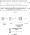
- FIG. 1 is a flowchart of a transmission method according to one embodiment.
- the transmission method provided in this embodiment may be applied to a first communication node. As shown in FIG. 1 , the method includes 110 and 120.
- indication information is sent.
- the indication information is used for indicating that a second communication node sends an uplink signal or receives a downlink signal.
- the transmission method in this embodiment through sending the indication information, it indicates that the second communication node sends the uplink signal or receives the downlink signal.
- the method is suitable for various signal transmission situations, improving the flexibility of signal transmission between the first communication node and the second communication node and guaranteeing the reliability of transmission.
- the indication information includes an antenna group association parameter.
- the antenna group association parameter corresponds to an antenna group for sending the uplink signal.
- the antenna group association parameter is configured in a sounding reference signal (SRS) resource configured through higher-layer signaling or an SRS resource set configured through the higher-layer signaling; or a cyclic redundancy check code corresponding to downlink control information (DCI) is scrambled according to a mask selected by the antenna group, where the indication information is sent through the DCI.
- SRS sounding reference signal
- DCI downlink control information
- the first communication node may be a base station
- the second communication node may be a UE.
- UE antennas can be divided into two groups. Each group of antennas supports 1T2R.
- the base station can determine a group of antennas with better configuration and indicates through signaling that the UE sends the uplink signal on that group of antennas.
- the method in which the antenna group for the UE sending the uplink signal is indicated through signaling includes at least one of the following: 1) The antenna group association parameter is configured in the SRS resource configured through the higher-layer signaling or the SRS resource set configured through the higher-layer signaling, where the antenna group association parameter is used for indicating antenna group 0 or antenna group 1; for example, antenna group association parameters are configured for antenna group 0 or antenna group 1 respectively so as to indicate the antenna group for sending an aperiodic SRS, and a corresponding aperiodic SRS-resource trigger is configured for an antenna group association parameter; 2) the antenna group for the UE sending the uplink signal is indicated dynamically through the DCI; 3) a cyclic redundancy check (CRC) added behind the DCI is scrambled using the mask selected by the antenna group so as to implement the function of dynamically indicating the antenna group.
- CRC cyclic redundancy check
- the UE has the following types of capabilities in sending/receiving antenna ports: t1r1-t1r2, t1r1-t1r2-t1r4, t1r1-t1r2-t2r4, t1r1-t2r2, and t1r1-t2r2-t4r4.
- t1r1-t1r2-t1r4 three parameters, t1r1, t1r2, and t1r4 may be configured in the SRS resource configured through the higher-layer signaling or the SRS resource set configured through the higher-layer signaling.
- aperiodic SRS-resource trigger 1 aperiodic SRS-resource trigger 2
- aperiodic SRS-resource trigger 3 are associated with and configured for the parameters respectively.
- the DCI dynamically triggers the aperiodic SRS, one configuration can be selected dynamically from t1r1, t1r2, and t1r4 to be used for signal transmission.
- the indication information includes a first slot offset parameter.
- the first slot offset parameter corresponds to a slot for sending an uplink signal.
- the uplink signal includes an aperiodic SRS.
- the method further includes configuring the first slot offset parameter in the SRS resource configured through the higher-layer signaling or the SRS resource set configured through the higher-layer signaling.
- the method further includes that in the case where a plurality of first slot offset parameters are configured in the SRS resource or the SRS resource set, the first slot offset parameters are determined according to an SRS request domain of the DCI.
- the first slot offset parameters are associated with a plurality of aperiodic SRS-resource trigger parameters or code points.
- a plurality of slot offset parameters are configured in the SRS resource set, and a corresponding aperiodic SRS-resource trigger is configured for each SlotOffset to enhance the flexibility of sending the aperiodic SRS.
- the base station configures two SlotOffsets for the SRS resource set of the UE.
- the two SlotOffsets are SlotOffset0 and SlotOffset 1 respectively.
- values of aperiodic SRS-resource triggers corresponding to SlotOffset0 and SlotOffset 1 are configured to be 1 and 3 respectively.
- the base station can dynamically select one SlotOffset and indicate the SlotOffset to the UE for sending the aperiodic SRS. For example, when the value of the SRS request domain in the DCI is 01, SlotOffset0 corresponding to the aperiodic SRS-resource trigger whose value is 1 is indicated to the UE; and when the value of the SRS request domain in the DCI is 11, SlotOffset1 corresponding to the aperiodic SRS-resource trigger whose value is 3 is indicated to the UE. Therefore, the flexibility of sending the aperiodic SRS is improved.
- first”, “second” and the like are only used for distinguishing different situations, but may represent the same parameter or different parameters.
- SlotOffset represents a first slot offset parameter in one embodiment and may also represent a second slot offset parameter in another embodiment, which is used for representing an offset between a slot for transmitting a signal and a slot for triggering the transmitted signal.
- n + SlotOffset represents a first target slot in one embodiment and may also represent a second target slot in another embodiment which is used for representing a slot for transmitting the signal.
- the indication information includes a sub-band parameter.
- the sub-band parameter corresponds to a sub-band for sending the uplink signal.
- the uplink signal includes the SRS.
- the indication information is used for indicating that the second communication node sends the SRS on the sub-band repeatedly or in a frequency-hopping manner.
- the method further includes that a broadband SRS sent by the second communication node is received and that the sub-band is determined through measuring the broadband SRS.
- the broadband SRS is sent through part of physical resource blocks in an activated bandwidth part (BWP) by the second communication node.
- BWP activated bandwidth part
- the first communication node indicates that the second communication node sends the SRS in two procedures to enhance the coverage of the SRS and improve the measurement accuracy of the SRS.
- the second communication node sends the broadband SRS on the activated bandwidth part (BWP); moreover, to enhance the coverage of the SRS, the SRS is sent only on part of the physical resource blocks (PRBs).
- BWP activated bandwidth part
- PRBs physical resource blocks
- the first communication node determines part of sub-bands to be accurately measured and indicates them to the second communication node through signaling.
- the second communication node After receiving the signaling indication, the second communication node sends the SRS on the part of sub-bands repeatedly or in a frequency-hopping manner.
- the indication information is sent through the DCI used for uplink scheduling or downlink scheduling.
- the uplink signal includes the SRS.
- the indication information includes a configuration parameter of the SRS.
- the configuration parameter includes at least one of the following: the corresponding antenna group association parameter for sending the SRS, a slot offset association parameter, the spatial relationship of a beam, a frequency domain position, or the cyclic shift of an SRS sequence.
- the first communication node triggers the sending of the SRS through the DCI for uplink or downlink scheduling without a PUSCH/PDSCH and dynamically indicates the configuration parameter of the SRS in the DCI.
- the configuration parameter includes at least one of the following: the corresponding antenna group association parameter for sending the SRS, the slot offset association parameter, the spatial relationship of the beam (the spatial relationship of the beam for sending the SRS can be determined according to the spatial relationship of a corresponding beam for sending an SRS, CSI-RS, or synchronization signal/ physical broadcast channel block (SSB) that is received), the frequency domain position, or the cyclic shift of the SRS sequence.
- the value of the domain, a UL-SCH indicator, in DCI format 0_1 may be set to 0, and/or the value or state in a CSI request domain is set to all 0s; accordingly, DCI format 0_1 is used for triggering the aperiodic SRS.
- the UE does not expect to receive DCI format 0_1 with the value of the UL-SCH indicator being 0, the CSI request domain being all 0s, and the SRS request domain being all 0s.
- the indication information is used for indicating that the second communication node sends the aperiodic SRS resource set on a first target slot.
- the first target slot is a (k + 1)th available slot or valid slot after a slot corresponding to the first slot offset parameter. k is 0 or a positive integer.
- the indication information is used for indicating that the second communication node sends the aperiodic SRS resource set on the first target slot.
- the first target slot is a (k + 1)th available slot or valid slot counted from a reference slot.
- the first target slot is a (k + 1)th available slot or valid slot among N slots counted from the reference slot.
- k is 0 or a positive integer.
- N is a positive integer within a first preset range or is equal to a product of E and (k + 1).
- E is a positive integer within a second preset range.
- the reference slot is a slot corresponding to a value obtained by rounding down a product of n and a first parameter.
- n corresponds to a slot for triggering the aperiodic SRS.
- the first parameter is a ratio of 2 to the ⁇ SRS th power to 2 to the ⁇ PDCCH th power.
- ⁇ SRS is the subcarrier spacing configuration of the triggered SRS.
- ⁇ PDCCH is the subcarrier spacing configuration of a physical downlink control channel (PDCCH) carrying a triggering command.
- the spacing between a first symbol of an SRS resource of the first target slot and a last symbol of the PDCCH triggering the aperiodic SRS is greater than or equal to a preset value.
- k is determined through at least one of the following manners: k is configured through radio resource control (RRC) signaling, k is equal to the first slot offset parameter, k is configured through the RRC signaling and corresponds to one SRS trigger state or one antenna group association parameter, k corresponds to a control resource set, corresponding to the slot where the PDCCH triggering the SRS is located, or k is a preset value.
- RRC radio resource control
- the indication information is used for indicating that the second communication node sends the aperiodic SRS on a second target slot.
- the second target slot is a first valid slot among slots configured in the SRS resource or SRS resource set of the second communication node.
- the second target slot is a slot, among corresponding valid slots in the SRS resource or SRS resource set of the second communication node, having the smallest slot offset against the slot where the PDCCH triggering the aperiodic SRS is located.
- the indication information is used for indicating that the second communication node sends the aperiodic SRS on a third target slot.
- the third target slot is a first valid slot among N slots after the slot where the PDCCH triggering the aperiodic SRS is located.
- the third target slot is a first valid slot among N slots after the slot corresponding to the first slot offset parameter.
- N is a positive integer within the first preset range.
- the indication information is used for indicating that the second communication node sends the aperiodic SRS on the slot corresponding to the first slot offset parameter or on part of symbols in a last slot among the N slots.
- a valid slot includes at least one of the following: an uplink slot, a special slot, or a flexible slot which is available or valid; an uplink slot, a special slot, or a flexible slot that is used for sending the SRS resource or at least one SRS resource in the SRS resource set; an uplink slot, a special slot, or a flexible slot that is used for sending the SRS resource or all SRS resources in the SRS resource set; an uplink slot that is used for sending the SRS resource or at least one SRS resource in the SRS resource set and does not conflict with an uplink slot that is used for sending another uplink signal, or a special slot that is used for sending the SRS resource or at least one SRS resource in the SRS resource set and does not conflict with a special slot that is used for sending another uplink signal, or a flexible slot that is used for sending the SRS resource or at least one SRS resource in the SRS resource set and does not conflict with a flexible slot that is used for sending another uplink signal; or a slot satisfying there is
- the first communication node may be a base station, and the second communication node may be a UE.
- the base station may configure the SRS resource set for the UE through the radio resource control (RRC) signaling.
- the SRS resource set includes the SlotOffset of the slot for sending the aperiodic SRS.
- DCI format 2-0 can dynamically modify a slot format and dynamically modify the SlotOffset-determined slot for sending the aperiodic SRS into a downlink slot. In this case, the SlotOffset parameter is no longer be applicable, resulting in a failure in determining the slot for sending the aperiodic SRS.
- FIG. 2 is a diagram illustrating that a slot offset parameter of signal transmission is modified according to one embodiment. As shown in FIG.
- slot n is the slot where the PDCCH triggering the SRS is located.
- slot n + SlotOffset is a valid slot
- the aperiodic SRS resource set is sent on slot n + SlotOffset.
- DCI format 2-0 modifies slot n + SlotOffset into a downlink slot
- the slot for sending the aperiodic SRS cannot be determined. To solve the preceding problem, at least one of the solutions below is included.
- slot n + SlotOffset is not a valid slot, and then it is predefined that the UE sends the aperiodic SRS resource set on the (k + 1)th valid slot after slot n or slot n + SlotOffset.
- k may be 0 or a positive integer.
- k is determined through at least one of the following manners: 1) The base station configures k for the UE through the RRC signaling; 2) k is equal to SlotOffset; 3) the base station configures a plurality of k values for the UE through the RRC signaling, and the k values correspond to a plurality of SRS trigger states or aperiodic SRS-resource triggers respectively; 4) k is associated with the control resource set (CORESET); 5) k is associated with the slot where the PDCCH triggering the SRS is located; or 6) k a preset value, for example, 0 or another preset value.
- the UE sends the aperiodic SRS resource set on the (k + 1)th valid slot after slot n.
- the spacing between the first symbol of the SRS resource of the (k + 1)th slot and the last symbol of the PDCCH triggering the aperiodic SRS is greater than or equal to N2 or is greater than or equal to N2 + 14.
- N2 is obtained according to the NR protocol of Rel-15 and is a value determined based on subcarrier spacing and the processing capacity of the UE.
- the spacing between the first symbol of the SRS resource of the (k + 1)th slot and the last symbol of the PDCCH triggering the aperiodic SRS is greater than or equal to a preset value A.
- An acquisition parameter of the preset value A includes at least one of the following: the minimum value between the PDCCH for scheduling an uplink channel and/or an uplink signal and a sending of the uplink channel and/or the unlink signal, or the subcarrier spacing relationship between the PDCCH and the SRS.
- preset value A when the subcarrier spacing of the PDCCH is the same as the subcarrier spacing of the SRS, preset value A is a first value; when the subcarrier spacing of the PDCCH is different from the subcarrier spacing of the SRS, preset value A is a second value; and the first value is smaller than or equal to the second value.
- N 2 is obtained according to the subcarrier spacing of the SRS. Different subcarrier spacing corresponds to different N 2 values.
- d 2,1 is 0 or 1.
- d 2,2 is BWP handover time; otherwise, d 2,2 is 0.
- ⁇ is 64.
- k may be 0 or a positive integer.
- k is determined through at least one of the following manners: 1) The base station configures k for the UE through the RRC signaling; 2) k is equal to SlotOffset; 3) the base station configures a plurality of k values for the UE through the RRC signaling, and the k values correspond to a plurality of SRS trigger states or aperiodic SRS-resource triggers respectively; 4) k is associated with the CORESET; 5) k is associated with the slot where the PDCCH triggering the SRS is located; or 6) k a preset value, for example, 0 or another preset value.
- the SRS resource set configured by the base station for the UE includes a plurality of SlotOffsets, for example, SlotOffset 1, SlotOffset 2, SlotOffset 3, and SlotOffset 4. Then the UE looks for a valid slot in slot n + SlotOffset 1, slot n + SlotOffset 2, slot n + SlotOffset 3, and slot n + SlotOffset 4 in sequence and sends the SRS resource set on a first valid slot. For example, it is determined first whether n + SlotOffset 1 is a valid slot. When n + SlotOffset 1 is an invalid slot, it is then determined whether n + SlotOffset 2 is a valid slot.
- n + SlotOffset 2 When n + SlotOffset 2 is a valid slot, the UE sends the SRS resource set on slot n + SlotOffset 2. Alternatively, the UE first determines whether each of slot n + SlotOffset 1, slot n + SlotOffset 2, slot n + SlotOffset 3, and slot n + SlotOffset 4 is a valid slot. For example, it is determined that slot n + SlotOffset 2 and slot n + SlotOffset 3 are valid slots. Then the UE sends the SRS resource set on slot min (n + SlotOffset 2, n + SlotOffset 3).
- the SRS resource in the triggered aperiodic SRS resource set is on at least one downlink symbol.
- the SRS resource is sent on a first valid slot among the N slots after slot n + SlotOffset or after slot n.
- N is a predefined integer between 1 and 50.
- N is a predefined integer between 1 and 50.
- solutions four and five may also be used. That is, the SRS resource set is sent on the first valid slot among the N slots after slot n + SlotOffset or after slot n. Moreover, when no valid slot is found among the N slots after slot n + SlotOffset, the UE sends part of the SRS resources in the SRS resource set on part of the symbols in slot n + SlotOffset or on part of the symbols in slot n + SlotOffset + N.
- N is a predefined integer between 1 and 50.
- a valid slot includes at least one of the conditions hereinafter.
- the valid slot is an uplink slot or a special slot or a flexible slot which is available or valid.
- a special slot refers to a mixed slot that can be used for sending both an uplink signal and a downlink signal.
- the transmission direction of each time-domain symbol where the at least one SRS resource is located is not downlinked.
- the transmission direction of a time-domain symbol where the SRS is located may be uplinked; alternatively, the time-domain symbol is a flexible symbol, for example, a flexible time-domain symbol.
- the transmission direction is acquired through slot structure information.
- the valid slot is an uplink slot or a special slot that is used for sending at least one SRS resource in the SRS resource set.
- the valid slot is an uplink slot or special slot that is used for sending all the SRS resources in the SRS resource set.
- the valid slot is an uplink slot or a special slot that is used for sending at least one SRS resource in the SRS resource set and does not conflict with another uplink signal.
- Another signal may refer to an uplink signal, for example, a periodic SRS, another aperiodic SRS, a PUSCH, or a PUCCH.
- the valid slot is a slot that is used for sending all the SRS resources in the SRS resource set and satisfies the minimum timing requirement between the PDCCH and the sending of the SRS. 6)
- the time interval between the PDCCH and a starting time-domain symbol of the SRS resource in the valid slot is greater than or equal to predetermined value A.
- the time interval between the PDCCH and a starting time-domain symbol of the SRS resource set in the valid slot is greater than or equal to predetermined value A.
- the valid time unit is within a predetermined time window after the PDCCH. 9) Time structure information does not change between the PDCCH and the valid slot.
- the time interval between a latest PDCCH, including the slot structure information, in front of the valid time unit and a starting symbol of the sounding reference signal resource in the valid slot is greater than or equal to a first predetermined time interval.
- the time structure information does not change after the PDCCH and within the predetermined time window.
- the same slot structure information is grounded between the PDCCH and the valid slot.
- the same slot structure information is grounded after the PDCCH and within the predetermined time window.
- the transmission direction of each time-domain symbol occupied by all the SRS resources in the SRS resource set is not downlinked; for example, it may be an uplink or flexible time-domain symbol or a special time-domain symbol. The transmission direction is acquired through the slot structure information.
- the valid slot is looked for at the SRS resource set level.
- the transmission direction of a time-domain symbol occupied by the SRS resource is not downlinked. For example, it may be an uplink or flexible time-domain symbol or a special time-domain symbol.
- the transmission direction is acquired through the slot structure information. That is, the valid slot is looked for at the SRS resource level. Whether to look for the valid slot based on the CSI-RS resource set level or the CSI-RS resource level can be optionally determined according to the configuration information in the CSI-RS resource set.
- the valid slot is looked for according to the CSI-RS resource set level; otherwise, the valid slot is looked for independently based on each CSI-RS resource.
- the preceding PDCCH is the PDCCH scheduling the SRS. 16)
- the valid slot is an uplink slot or a special slot that enables the sending of all the SRS resources in the SRS resource set not to conflict with another signal.
- the UE when the UE receives, on slot n, the DCI triggering the aperiodic SRS, the UE sends the aperiodic SRS resource set on the (k+1)th valid slot among 10 (k + 1) slots counted from n ⁇ 2 ⁇ SRS 2 ⁇ PDCCH .
- k is a value configured through higher-layer parameter SlotOffset.
- ⁇ SRS is the subcarrier spacing configuration of the triggered SRS.
- ⁇ PDCCH is the subcarrier spacing configuration of the PDCCH carrying the triggering command.
- the slot satisfying that there is at least one uplink symbol used for sending the SRS resource or sending all the SRS resources in the SRS resource set and satisfying the minimum timing requirement between the PDCCH triggering the aperiodic SRS and the sending of all the SRS resources in the resource set is a valid slot.
- only an aperiodic SRS resource triggered by the latest DCI is sent.
- the indication information includes a second slot offset parameter.
- the second slot offset parameter corresponds to a slot for receiving a downlink signal.
- the downlink signal includes a channel state information reference signal (CSI-RS).
- CSI-RS channel state information reference signal
- the indication information is used for indicating that the second communication node receives an aperiodic CSI-RS.
- the method further includes configuring the second slot offset parameter in a CSI-RS resource configured through the higher-layer signaling or a CSI-RS resource set configured through the higher-layer signaling.
- the indication information is used for indicating that the first communication node sends the aperiodic CSI-RS resource set on a fourth target slot.
- the fourth target slot is an (h + 1)th available slot or valid slot counted from a slot for triggering the aperiodic CSI-RS resource set.
- the fourth target slot is an (h + 1)th available slot or valid slot among M slots counted from the slot for triggering the aperiodic CSI-RS resource set.
- h is 0 or a positive integer.
- M is a positive integer within the first preset range or is equal to a product of F and (h + 1).
- F is a positive integer within the second preset range.
- h is determined through at least one of the following manners: h is configured through the RRC signaling, h is equal to the second slot offset parameter, h is configured through the RRC signaling and corresponds to one CSI-RS trigger state, h corresponds to the control resource set, h corresponds to the slot where the PDCCH triggering the CSI-RS is located, or h is a preset value.
- the indication information is used for indicating that the first communication node sends the aperiodic CSI-RS on a fifth target slot.
- the fifth target slot is a first valid slot among slots configured in the CSI-RS resource set of the second communication node.
- the fifth target slot is a slot having the smallest slot offset among valid slots in the CSI-RS resource set of the second communication node.
- the indication information is used for indicating that the first communication node sends the aperiodic CSI-RS on the fifth target slot.
- the fifth target slot is a first valid slot among M slots after the slot where the PDCCH triggering the aperiodic CSI-RS is located.
- the fifth target slot is a first valid slot among M slots after a slot corresponding to the second slot offset parameter.
- M is a positive integer within the second preset range.
- the indication information is used for indicating that the second communication node receives the downlink signal and wherein the indication information does not include the second slot offset parameter
- the indication information is used for indicating that the first communication node sends the aperiodic CSI-RS resource set on the fifth target slot.
- the fifth target slot is the first valid slot among the M slots after the slot where the PDCCH triggering the aperiodic CSI-RS is located.
- the fifth target slot is the first valid slot among the M slots after the slot corresponding to the second slot offset parameter.
- M is a positive integer within the second preset range.
- the indication information is used for indicating that the first communication node sends the aperiodic CSI-RS on the slot corresponding to the second slot offset parameter or on part of symbols in a last slot among the M slots.
- a valid slot includes at least one of the following: a downlink slot, a special slot, or a flexible slot which is available or valid; an uplink slot, a special slot, or a flexible slot that is used for sending the CSI-RS resource or at least one CSI-RS resource in the CSI-RS resource set; an uplink slot, a special slot, or a flexible slot that is used for sending the CSI-RS resource or all CSI-RS resources in the CSI-RS resource set; an uplink slot that is used for sending a CSI-RS resource or at least one CSI-RS resource in the CSI-RS resource set and does not conflict with an uplink slot that is used for sending another uplink signal, a special slot that is used for sending a CSI-RS resource or at least one CSI-RS resource in the CSI-RS resource set and does not conflict with a special slot that is used for sending another uplink signal, or a flexible slot that is used for sending a CSI-RS resource or at least one CSI-RS resource in the CSI
- the first communication node may be a base station, and the second communication node may be a UE.
- the base station may configure the SRS resource set for the UE through the radio resource control (RRC) signaling.
- the SRS resource set includes a slot offset parameter aperiodicTriggeringOffset for sending the aperiodic CSI-RS. It is assumed that the slot where the PDCCH triggering the aperiodic CSI-RS is located is n.
- DCI format 2-0 can dynamically modify a slot format and dynamically modify an aperiodicTriggeringOffset-determined slot (that is, slot n + aperiodicTriggeringOffset) for sending the aperiodic CSI-RS into an uplink slot.
- the aperiodicTriggeringOffset parameter is no longer be applicable, resulting in a failure in determining the slot for sending the aperiodic CSI-RS.
- slot n + aperiodicTriggeringOffset is not a valid slot, and then it is predefined that the BS sends the aperiodic CSI-RS resource set on the (h + 1)th valid slot after slot n or slot n + aperiodicTriggeringOffset.
- h may be 0 or a positive integer.
- h is determined through at least one of the following manners: 1) The base station configures h for the UE through the RRC signaling; 2) h is equal to the n + aperiodicTriggeringOffset; 3) the base station configures a plurality of h values for the UE through the RRC signaling, and the h values correspond to a plurality of CSI-RS trigger states respectively; 4) h is associated with the CORESET; 5) h is associated with the slot where the physical downlink control channel (PDCCH) triggering the CSI-RS is located; or 6) h a preset value, for example, 0 or another preset value.
- PDCCH physical downlink control channel
- the base station sends the aperiodic CSI-RS resource set on the (h + 1)th valid slot after slot n.
- h may be 0 or a positive integer.
- h is determined through at least one of the following manners: 1) The base station configures h for the UE through the RRC signaling; 2) h is equal to the n + aperiodicTriggeringOffset; 3) the base station configures a plurality of h values for the UE through the RRC signaling, and the h values correspond to a plurality of CSI-RS trigger states respectively; 4) h is associated with the CORESET; 5) h is associated with the slot where the physical downlink control channel (PDCCH) triggering the CSI-RS is located; or 6) h a preset value, for example, 0 or another preset value.
- PDCCH physical downlink control channel
- the CSI-RS resource set configured by the base station for the UE includes a plurality of aperiodicTriggeringOffsets, for example, aperiodicTriggeringOffset 1, aperiodicTriggeringOffset 2, aperiodicTriggeringOffset 3, and aperiodicTriggeringOffset 4. Then the UE looks for a valid slot in slot n + aperiodicTriggeringOffset 1, slot n + aperiodicTriggeringOffset 2, slot n + aperiodicTriggeringOffset 3, and slot n + aperiodicTriggeringOffset 4 in sequence and sends the CSI-RS resource set on a first valid slot.
- aperiodicTriggeringOffsets for example, aperiodicTriggeringOffset 1, aperiodicTriggeringOffset 2, aperiodicTriggeringOffset 3, and aperiodicTriggeringOffset 4.
- n + aperiodicTriggeringOffset 1 is a valid slot.
- n + aperiodicTriggeringOffset 1 is an invalid slot
- n + aperiodicTriggeringOffset 2 is a valid slot.
- the UE sends the SRS resource set on slot n + aperiodicTriggeringOffset. The rest can be done in the same manner.
- the base station first determines whether each of slot n + aperiodicTriggeringOffset 1, slot n + aperiodicTriggeringOffset 2, slot n + aperiodicTriggeringOffset 3, and slot n + aperiodicTriggeringOffset 4 is a valid slot. For example, it is determined that slot n + aperiodicTriggeringOffset 2 and slot n + aperiodicTriggeringOffset 3 are valid slots. Then UE sends the CSI-RS resource set on slot min (n + aperiodicTriggeringOffset 2, n + aperiodicTriggeringOffset 3).
- the CSI-RS resource in the triggered aperiodic CSI-RS resource set is on at least one uplink symbol.
- the CSI-RS resource is sent on a first valid slot among the M slots after slot n + aperiodicTriggeringOffset or after slot n.
- M is a predefined integer between 1 and 50.
- the base station when no valid slot is found among the M slots after slot n + aperiodicTriggeringOffset, the base station sends part of the CSI-RS resources in the CSI-RS resource set on part of symbols in slot n + aperiodicTriggeringOffset or on part of symbols in slot n + aperiodicTriggeringOffset + N.
- M is a predefined integer between 1 and 50.
- solutions four and five may also be used. That is, the CSI-RS resource set is sent on the first valid slot among the M slots after slot n + aperiodicTriggeringOffset or after slot n.
- the UE when no valid slot is found among the M slots after slot n + aperiodicTriggeringOffset, the UE sends part of the SRS resources in the SRS resource set on part of the symbols in slot n + aperiodicTriggeringOffset or on part of the symbols in slot n + aperiodicTriggeringOffset + N.
- M is a predefined integer between 1 and 50.
- a valid slot includes at least one of the conditions hereinafter. 1) The valid slot is a downlink slot or a special slot or a flexible slot which is available or valid. 2) The valid slot is a downlink slot or a special slot that is used for sending at least one CSI-RS resource in the CSI-RS resource set. 3) The valid slot is a downlink slot or a special slot that is used for sending all CSI-RS resources in the CSI-RS resource set. 4) The valid slot is a downlink slot or a special slot that is used for sending at least one CSI-RS resource in the CSI-RS resource set and does not conflict with a special slot that is used for sending another downlink signal.
- the valid slot is a slot that is used for sending all the CSI-RS resources in the CSI-RS resource set and satisfies the minimum timing requirement between the PDCCH and the sending of the CSI-RS.
- the transmission direction of each time-domain symbol occupied by all the CSI-RS resources in the CSI-RS resource set is not uplinked; for example, it may be a downlink or flexible time-domain symbol or a special time-domain symbol.
- the transmission direction is acquired through the slot structure information. That is, the valid slot is looked for at the CSI-RS resource set level.
- the transmission direction of a time-domain symbol occupied by the CSI-RS resource is not uplinked.
- the transmission direction is acquired through the slot structure information. That is, the valid slot is looked for at the CSI-RS resource level. Whether to look for the valid slot based on the CSI-RS resource set level or the CSI-RS resource level can be optionally determined according to the configuration information in the CSI-RS resource set. For example, when on/off is configured, the valid slot is looked for according to the CSI-RS resource set level; otherwise, the valid slot is looked for independently based on each CSI-RS resource.
- the spacing between the PDCCH and a starting time-domain symbol of the CSI-RS resource set in the slot is greater than a second predetermined value.
- the second predetermined value is beamSwitchTiming.
- beamSwitchTiming represents a minimum timing interval in which the transmission configuration indication indicated by the PDCCH is applied to the CSI-RS for a reception.
- beamSwitchTiming represents a minimum timing interval between the PDCCH and the CSI-RS.
- the valid slot is within the predetermined time window after the PDCCH.
- the time structure information does not change between the PDCCH and the valid slot.
- the time interval between the latest PDCCH, including the slot structure information, in front of the valid slot and the starting symbol of the sounding reference signal resource in the valid slot is greater than or equal to the first predetermined time interval.
- the time structure information does not change after the PDCCH and within the predetermined time window.
- the same slot structure information is grounded between the PDCCH and the valid slot. 13) The same slot structure information is grounded after the PDCCH and within the predetermined time window.
- the preceding PDCCH is the PDCCH scheduling the CSI-RS.
- the first communication node sends the aperiodic CSI-RS resource set on the (k + 1)th valid slot among 10 (k + 1) slots counted from slot n.
- k is a value configured through the higher-layer parameter aperiodicTriggeringOffset.
- a slot satisfying that there is at least one downlink symbol used for sending all the CSI-RS resources in the CSI-RS resource set and satisfying the minimum timing requirement between the PDCCH triggering the aperiodic CSI-RS and the sending of all the CSI-RS resources in the CSI-RS resource set is a valid slot. In the case where a plurality of triggered CSI-RS resources conflict with each other, only an aperiodic CSI-RS resource triggered by the latest DCI is sent.
- the method further includes that, in the case where at least one resource in the triggered aperiodic SRS resource set or aperiodic CSI-RS resource set conflicts with another to-be-transmitted signal, removing a symbol in the conflict in the resource set, postponing the sending of the aperiodic SRS or aperiodic CSI-RS, or removing the to-be-transmitted signal in the conflict and preferentially transmitting the aperiodic SRS or aperiodic CSI-RS.
- the indication information is further used for indicating that, in the case where the sending of at least two aperiodic SRSs or at least two aperiodic CSI-RSs is triggered by the same DCI or different types of DCI, or in the case where a plurality of triggered SRS resources or SRS resource sets conflict with each other or a plurality of triggered CSI-RS resources or CSI-RS resource sets conflict with each other, only an aperiodic SRS resource or SRS resource set triggered by the latest DCI or only an aperiodic CSI-RS resource or CSI-RS resource set triggered by the latest DCI is transmitted, or only an aperiodic SRS resource or SRS resource set with the smallest or largest resource set identity or only an aperiodic CSI-RS resource or CSI-RS resource set with the smallest or largest resource set identity is transmitted.
- one or more resources in the triggered SRS resource set (or CSI-RS resource set) conflict with another uplink signal (or downlink signal) one of the following manners is taken: A resource or symbol in the conflict is removed; the sending of the entire SRS resource set (or CSI-RS resource set) is postponed; or the uplink signal (or downlink signal) in the conflict is removed and the SRS resource set (or CSI-RS resource set) is sent preferentially.
- a plurality of SRS resource sets (or CSI-RS resource sets) to be sent simultaneously only an SRS resource set (or CSI-RS resource set) triggered by the latest DCI is sent, or only an SRS resource set (or CSI-RS resource set) with a small or large resource set identity (ID) is sent.
- ID resource set identity
- the indication information includes a third slot offset parameter.
- the third slot offset parameter corresponds to a slot for sending a downlink signal.
- the downlink signal includes a PDSCH.
- the indication information is used for indicating that the second communication node receives the PDSCH.
- the method further includes configuring at least one information element through the RRC signaling.
- the at least one information element is used for configuring the time-domain relationship between the PDCCH and the PDSCH.
- the at least one information element corresponds to at least one slot offset parameter respectively. In the case where at least two information elements are included, it is determined through DCI signaling that a slot offset parameter corresponding to one information element is the third slot offset parameter.
- the indication information is used for indicating that the second communication node receives the PDSCH on a sixth target slot.
- the sixth target slot is an (r + 1)th available or valid downlink slot or special slot after the slot where the PDCCH is located or after a slot corresponding to a sixth slot offset parameter. r is 0 or a positive integer.
- r is determined through at least one of the following manners: r is configured through the RRC signaling, r is equal to the third slot offset parameter, r is configured through the RRC signaling and corresponds to one CSI-RS trigger state, r corresponds to the control resource set, r corresponds to the slot where the PDCCH scheduling the PDSCH is located, or r is a preset value.
- the first communication node may be a base station
- the second communication node may be a UE.
- the base station configures one or more information elements (IEs) PDSCH-TimeDomainResourceAllocations for the UE through the RRC signaling.
- the one or more information elements PDSCH-TimeDomainResourceAllocations are used for configuring the time-domain relationship between the PDCCH and the PDSCH.
- An information element PDSCH-TimeDomainResourceAllocation includes parameter k0 representing the offset between a slot where the PDSCH is located and the slot where the PDCCH scheduling the PDSCH is located.
- one information element may be dynamically selected from the information elements through the DCI signaling so as to determine k0 and thus determine the slot for sending the PDSCH.
- DCI format 2-0 can dynamically modify a slot format.
- the k0-determined slot for sending the PDSCH is dynamically modified into an uplink slot, the base station cannot send the PDSCH scheduled by the PDCCH.
- the RRC signaling can configure limited k0 values for the dynamic selection of the base station, limiting the resource scheduling of the base station.
- the base station when the preceding problem is encountered, it may be predefined that the base station sends the PDSCH on the k0th available or valid downlink slot/special slot after the slot where the PDCCH is located. Alternatively, it may be predefined that the base station sends the PDSCH on the (r + 1)th available or valid downlink slot/special slot after the slot determined by parameter k0. r may be 0 or a positive integer.
- r is determined through at least one of the following manners: 1) The base station configures r for the UE through the RRC signaling; 2) the base station configures a plurality of r values for the UE through the RRC signaling, and the r values correspond to a plurality of CSI-RS trigger states respectively; 3) r is associated with the CORESET; or 4) r is associated with the slot where the PDCCH scheduling the PDSCH is located.
- the transmission direction of a time-domain symbol occupied by the PDSCH in the valid slot is not uplinked.
- the transmission direction is determined through the slot structure information.
- the indication information includes a fourth slot offset parameter.
- the fourth slot offset parameter corresponds to a slot for sending an uplink signal.
- the uplink signal includes a PUSCH.
- the indication information is used for indicating that the second communication node sends the PUSCH.
- the method further includes configuring at least one information element through the RRC signaling.
- the at least one information element is used for configuring the time-domain relationship between the PDCCH and the PUSCH.
- the at least one information element corresponds to at least one slot offset parameter respectively. In the case where at least two information elements are included, it is determined through the DCI signaling that a slot offset parameter corresponding to one information element is the fourth slot offset parameter.
- the indication information is used for indicating that the second communication node receives the PUSCH on a seventh target slot.
- the seventh target slot is a (y + 1)th available or valid downlink slot or special slot after the slot where the PDCCH is located or after a slot corresponding to a fourth slot offset association parameter.
- y is 0 or a positive integer.
- y is determined through at least one of the following manners: y is configured through the RRC signaling, y is equal to the fourth slot offset parameter, y is configured through the RRC signaling and corresponds to one CSI-RS trigger state, y correspond to the control resource set, or y correspond to the slot where the PDCCH scheduling the PDSCH is located.
- the base station configures one or more information elements (IEs) PUSCH-TimeDomainResourceAllocations for the UE through the RRC signaling.
- the one or more information elements PUSCH-TimeDomainResourceAllocations are used for configuring the time-domain relationship between the PDCCH and the PUSCH.
- An information element PUSCH-TimeDomainResourceAllocation includes parameter k2 representing the offset between a slot where the PUSCH is located and the slot where the PDCCH scheduling the PUSCH is located.
- one information element may be dynamically selected from the information elements through the DCI signaling so as to determine k2 and thus determine the slot for sending the PUSCH.
- DCI format 2-0 can dynamically modify a slot format.
- the UE cannot send the PUSCH scheduled by the PDCCH.
- the RRC signaling can configure limited k2 values for the dynamic selection of the base station, limiting the resource scheduling of the base station.
- the UE when the preceding problem is encountered, it may be predefined that the UE sends the PUSCH on the k2nd available or valid uplink slot/special slot after the predetermined time A of the PDCCH slot. Alternatively, it may be predefined that the UE sends the PUSCH on the (y + 1)th available or valid uplink slot/special slot after the slot determined by parameter k2. y may be 0 or a positive integer.
- y is determined through at least one of the following manners: 1) The base station configures y for the UE through the RRC signaling; 2) the base station configures a plurality of y values for the UE through the RRC signaling, and the y values correspond to a plurality of CSI-RS trigger states respectively; 3) y is associated with the CORESET; or 4) y is associated with the slot where the PDCCH scheduling the PUSCH is located.
- the transmission direction of a time-domain symbol occupied by the PUSCH in the valid slot is not downlinked.
- the transmission direction is determined through the slot structure information.
- the indication information includes a fifth slot offset parameter.
- the fifth slot offset parameter corresponds to a slot for sending an uplink signal.
- the uplink signal includes a PUCCH associated with acknowledgment and non-acknowledgment information.
- the indication information is used for indicating that the second communication node sends the PUCCH associated with acknowledgment and non-acknowledgment information.
- the method further includes configuring at least one preset parameter through the RRC signaling.
- the at least one preset parameter is used for configuring the time-domain relationship between the PDSCH and the PUCCH.
- the indication information is used for indicating that the second communication node sends the PUCCH on an eighth target slot.
- the eighth target slot is an (x + 1)th available or valid downlink slot or special slot after the slot where the PDSCH is located or after a slot corresponding to a fifth slot offset association parameter.
- x is 0 or a positive integer.
- x is determined through at least one of the following manners: x is configured through the RRC signaling, x is equal to the fifth slot offset parameter, x is configured through the RRC signaling and corresponds to one CSI-RS trigger state, x corresponds to the control resource set, or x corresponds to the slot where the PDCCH scheduling the PDSCH is located.
- the base station configures parameter k1 for the UE through signaling.
- Parameter k1 is used for indicating the slot offset relationship between the PDSCH and the PUCCH with ACK/NACK.
- DCI format 2-0 can dynamically modify a slot format.
- the UE cannot send the PUCCH.
- the RRC signaling can configure limited k1 values for the dynamic selection of the base station, limiting the resource scheduling of the base station.
- the UE when the preceding problem is encountered, it may be predefined that the UE sends the PUCCH on the k1st available or valid uplink slot/special slot after the slot where the PDSCH is located. Alternatively, it may be predefined that the UE sends the PUCCH on the (x + 1)th available or valid uplink slot/special slot after the slot determined by parameter k1. x may be 0 or a positive integer.
- x is determined through at least one of the following manners: 1) The base station configures x for the UE through the RRC signaling; 2) the base station configures a plurality of x values for the UE through the RRC signaling, and the x values correspond to a plurality of CSI-RS trigger states respectively; 3) x is associated with the control resource set (CORESET); or 4) x is associated with the slot where the PDSCH is located.
- the transmission direction of a time-domain symbol occupied by the PUCCH in the valid slot is not downlinked. The transmission direction is determined through the slot structure information.
- the slot structure information includes at least one of the following: The slot structure information is according to a time-domain symbol position where a synchronization signal is located; the slot structure information is according to a semi-persistent frame structure; the slot structure information is according to DCI format 2_0; the slot structure information is according to a time-domain symbol where a PRACH is located; the slot structure information is slot structure information before the PDCCH; the slot structure information in each time unit after the PDCCH includes valid slot structure information in each time unit; or when the transmission direction of a time-domain symbol is determined, the slot structure information is slot structure information with a higher priority than a target slot. For example, it is determined through the slot structure information that the transmission direction of one time-domain symbol is uplinked.
- the target signal is the preceding aperiodic CSI-RS/PDSCH.
- the priority of the slot structure information is higher; that is, the transmission direction of the time-domain symbol is uplinked.
- the priority of the PDSCH/PUSCH/AP-SRS/AP-CSI-RS scheduled by the DCI is higher than the priority of a periodic signal.
- the transmission direction of one time-domain symbol includes uplink, downlink, and flexible. When the transmission direction is flexible, the transmission direction may be modified by the target signal to be uplinked or downlinked.
- the slot structure information satisfies at least one of the following features: 1) In the case of determining the transmission direction of a time-domain symbol, the priority of the slot structure information is higher than the priority of the slot structure information of a target signal; 2) the time structure information does not change between the PDCCH and the valid slot; 3) the time interval between the latest PDCCH, including the slot structure information, in front of the valid time unit and the starting symbol of the sounding reference signal resource in the valid slot is greater than or equal to the first predetermined time interval; 4) the time structure information does not change after the PDCCH and within the predetermined time window; 5) the same slot structure information is grounded between the PDCCH and the valid slot; or 6) the same slot structure information is grounded after the PDCCH and within the predetermined time window.
- a preceding time unit is a slot.
- this embodiment does not exclude determining another time unit, for example, a subframe or a frame, where an SRS is located according to the preceding rules.
- FIG. 3 is a flowchart of a transmission method according to one embodiment.
- the transmission method provided in this embodiment may be applied to a second communication node. As shown in FIG. 3 , the method includes 210 and 220.
- indication information is received.
- the indication information is used for indicating that the second communication node sends an uplink signal or indicating that the second communication node receives a downlink signal.
- signal transmission is performed with a first communication node according to the indication information.
- the transmission method in this embodiment through the indication information, indicates that the second communication node sends the uplink signal or receives the downlink signal.
- the method is suitable for various signal transmission situations, improving the flexibility of signal transmission between the first communication node and the second communication node and guaranteeing the reliability of transmission.
- the indication information includes an antenna group association parameter.
- the antenna group association parameter corresponds to an antenna group for sending the uplink signal.
- the antenna group association parameter is configured in a sounding reference signal (SRS) resource configured through higher-layer signaling or an SRS resource set configured through the higher-layer signaling.
- SRS sounding reference signal
- a cyclic redundancy check code corresponding to downlink control information is scrambled by the first communication node according to a mask selected by the antenna group, where the indication information is sent through the DCI.
- DCI downlink control information
- the indication information includes a first slot offset parameter.
- the first slot offset parameter corresponds to a slot for sending an uplink signal.
- the uplink signal includes an aperiodic SRS.
- the first slot offset parameter is configured by the first communication node in the SRS resource configured through the higher-layer signaling or the SRS resource set configured through the higher-layer signaling.
- the first slot offset parameters are determined by the first communication node according to an SRS request domain of the DCI.
- the first slot offset parameters are associated with a plurality of aperiodic SRS-resource trigger parameters or code points.
- the indication information includes a sub-band parameter.
- the sub-band parameter corresponds to a sub-band for sending the uplink signal.
- the uplink signal includes the SRS.
- the indication information is used for indicating that the second communication node sends the SRS on the sub-band repeatedly or in a frequency-hopping manner.
- the method further includes sending a broadband SRS to the first communication node.
- the first communication node determines the sub-band through measuring the broadband SRS.
- the broadband SRS is sent through part of physical resource blocks in an activated bandwidth part (BWP) by the second communication node.
- BWP activated bandwidth part
- the indication information is sent through the DCI used for uplink scheduling or downlink scheduling.
- the uplink signal includes the SRS.
- the indication information includes a configuration parameter of the SRS.
- the configuration parameter includes at least one of the following: the corresponding antenna group association parameter for sending the SRS, a slot offset association parameter, the spatial relationship of a beam, a frequency domain position, or the cyclic shift of an SRS sequence.
- the indication information is used for indicating that the second communication node sends the aperiodic SRS resource set on a first target slot.
- the first target slot is a (k + 1)th available slot or valid slot after a slot corresponding to the first slot offset parameter. k is 0 or a positive integer.
- the indication information is used for indicating that the second communication node sends the aperiodic SRS resource set on the first target slot.
- the first target slot is a (k + 1)th available slot or valid slot counted from a reference slot.
- the first target slot is a (k + 1)th available slot or valid slot among N slots counted from the reference slot.
- k is 0 or a positive integer.
- N is a positive integer within a first preset range or is equal to a product of E and (k + 1).
- E is a positive integer within a second preset range.
- the reference slot is a slot corresponding to a value obtained by rounding down a product of n and a first parameter.
- n corresponds to a slot for triggering the aperiodic SRS.
- the first parameter is a ratio of 2 to the ⁇ SRS th power to 2 to the ⁇ PDCCH th power.
- ⁇ SRS is the subcarrier spacing configuration of the triggered SRS.
- ⁇ PDCCH is the subcarrier spacing configuration of a physical downlink control channel (PDCCH) carrying a triggering command.
- the spacing between a first symbol of an SRS resource of the first target slot and a last symbol of the PDCCH triggering the aperiodic SRS is greater than or equal to a preset value.
- k is determined through at least one of the following manners: k is configured through radio resource control (RRC) signaling, k is equal to the first slot offset parameter, k is configured through the RRC signaling and corresponds to one SRS trigger state or one antenna group association parameter, k corresponds to a control resource set, k corresponds to the slot where the PDCCH triggering the SRS is located, or k is a preset value.
- RRC radio resource control
- the indication information is used for indicating that the second communication node sends the aperiodic SRS on a second target slot.
- the second target slot is a first valid slot among slots configured in the SRS resource or SRS resource set of the second communication node.
- the second target slot is a slot, among corresponding valid slots in the SRS resource or SRS resource set of the second communication node, having the smallest slot offset against the slot where the PDCCH triggering the aperiodic SRS is located.
- the indication information is used for indicating that the second communication node sends the aperiodic SRS on a third target slot.
- the third target slot is a first valid slot among N slots after the slot where the PDCCH triggering the aperiodic SRS is located.
- the third target slot is a first valid slot among N slots after the slot corresponding to the first slot offset parameter.
- N is a positive integer within the first preset range.
- the indication information is used for indicating that the second communication node sends the uplink signal and where the indication information does not include the first slot offset parameter
- the indication information is used for indicating that the second communication node sends the aperiodic SRS on the third target slot.
- the third target slot is the first valid slot among the N slots after the slot where the PDCCH triggering the aperiodic SRS is located.
- the third target slot is the first valid slot among the N slots after the slot corresponding to the first slot offset parameter.
- N is a positive integer within the first preset range.
- the indication information is used for indicating that the second communication node sends the aperiodic SRS on the slot corresponding to the first slot offset parameter or on part of symbols in a last slot among the N slots.
- a valid slot includes at least one of the following: an uplink slot, a special slot, or a flexible slot which is available or valid; an uplink slot, a special slot, or a flexible slot that is used for sending the SRS resource or at least one SRS resource in the SRS resource set; an uplink slot, a special slot, or a flexible slot that is used for sending the SRS resource or all SRS resources in the SRS resource set; an uplink slot that is used for sending the SRS resource or at least one SRS resource in the SRS resource set and does not conflict with an uplink slot that is used for sending another uplink signal, or a special slot that is used for sending the SRS resource or at least one SRS resource in the SRS resource set and does not conflict with a special slot that is used for sending another uplink signal, or a flexible slot that is used for sending the SRS resource or at least one SRS resource in the SRS resource set and does not conflict with a flexible slot that is used for sending another uplink signal; or a slot satisfying that there
- the indication information includes a second slot offset parameter.
- the second slot offset parameter corresponds to a slot for receiving a downlink signal.
- the downlink signal includes a channel state information-reference signal (CSI-RS).
- CSI-RS channel state information-reference signal
- the indication information is used for indicating that the second communication node receives an aperiodic CSI-RS.
- the second slot offset parameter is configured by the first communication node in the CSI-RS resource configured through the higher-layer signaling or the CSI-RS resource set configured through the higher-layer signaling.
- the indication information is used for indicating that the first communication node sends the aperiodic CSI-RS resource set on a fourth target slot.
- the fourth target slot is an (h + 1)th available slot or valid slot counted from a slot for triggering the aperiodic CSI-RS resource set.
- the fourth target slot is an (h + 1)th available slot or valid slot among M slots counted from the slot for triggering the aperiodic CSI-RS resource set.
- h is 0 or a positive integer.
- M is a positive integer within the first preset range or is equal to a product of F and (h + 1).
- F is a positive integer within the second preset range.
- h is determined through at least one of the following manners: h is configured through the RRC signaling, h is equal to the second slot offset parameter, h is configured through the RRC signaling and corresponds to one CSI-RS trigger state, h corresponds to the control resource set, or h corresponds to the slot where the PDCCH triggering the CSI-RS is located.
- the indication information is used for indicating that the first communication node sends the aperiodic CSI-RS on a fifth target slot.
- the fifth target slot is a first valid slot among slots configured in the CSI-RS resource set of the second communication node.
- the fifth target slot is a slot having the smallest slot offset among valid slots in the CSI-RS resource set of the second communication node.
- the indication information is used for indicating that the first communication node sends the aperiodic CSI-RS on the fifth target slot.
- the fifth target slot is a first valid slot among M slots after the slot where the PDCCH triggering the aperiodic CSI-RS is located.
- the fifth target slot is a first valid slot among M slots after a slot corresponding to the second slot offset parameter.
- M is a positive integer within the second preset range.
- the indication information is used for indicating that the second communication node receives the downlink signal and wherein the indication information does not include the second slot offset parameter
- the indication information is used for indicating that the first communication node sends the aperiodic CSI-RS resource set on the fifth target slot.
- the fifth target slot is the first valid slot among the M slots after the slot where the PDCCH triggering the aperiodic CSI-RS is located.
- the fifth target slot is the first valid slot among the M slots after the slot corresponding to the second slot offset parameter.
- M is a positive integer within the second preset range.
- the indication information is used for indicating that the first communication node sends the aperiodic CSI-RS on the slot corresponding to the second slot offset parameter or on part of symbols in a last slot among the M slots.
- a valid slot includes at least one of the following: a downlink slot, a special slot, or a flexible slot which is available or valid; an uplink slot, a special slot, or a flexible slot that is used for sending the CSI-RS resource or at least one CSI-RS resource in the CSI-RS resource set; an uplink slot, a special slot, or a flexible slot that is used for sending the CSI-RS resource or all CSI-RS resources in the CSI-RS resource set; an uplink slot that is used for sending a CSI-RS resource or at least one CSI-RS resource in the CSI-RS resource set and does not conflict with an uplink slot that is used for sending another uplink signal, a special slot that is used for sending a CSI-RS resource or at least one CSI-RS resource in the CSI-RS resource set and does not conflict with a special slot that is used for sending another uplink signal, or a flexible slot that is used for sending a CSI-RS resource or at least one CSI-RS resource in the CSI
- the method further includes that, in the case where at least one resource in the triggered aperiodic SRS resource set or aperiodic CSI-RS resource set conflicts with another to-be-transmitted signal, removing a symbol in the conflict in the resource set, postponing the sending of the aperiodic SRS or aperiodic CSI-RS, or removing the to-be-transmitted signal in the conflict and preferentially transmitting the aperiodic SRS or aperiodic CSI-RS.
- the indication information is further used for indicating that, in the case where the sending of at least two aperiodic SRSs or at least two aperiodic CSI-RSs is triggered by the same DCI or different types of DCI, or in the case where a plurality of triggered SRS resources or SRS resource sets conflict with each other or a plurality of triggered CSI-RS resources or CSI-RS resource sets conflict with each other, only an aperiodic SRS resource or SRS resource set triggered by the latest DCI or only an aperiodic CSI-RS resource or CSI-RS resource set triggered by the latest DCI is transmitted, or only an aperiodic SRS resource or SRS resource set with the smallest or largest resource set identity or only an aperiodic CSI-RS resource or CSI-RS resource set with the smallest or largest resource set identity is transmitted.
- the indication information includes a third slot offset parameter.
- the third slot offset parameter corresponds to a slot for sending a downlink signal.
- the downlink signal includes a PDSCH.
- the indication information is used for indicating that the second communication node receives the PDSCH.
- the first communication node is further used for configuring at least one information element through the RRC signaling.
- the at least one information element is used for configuring the time-domain relationship between the PDCCH and the PDSCH.
- the at least one information element corresponds to at least one slot offset parameter respectively. In the case where at least two information elements are included, it is determined through DCI signaling that a slot offset parameter corresponding to one information element is the third slot offset parameter.
- the indication information is used for indicating that the second communication node receives the PDSCH on a sixth target slot.
- the sixth target slot is an (r + 1)th available or valid downlink slot or special slot after the slot where the PDCCH is located or after a slot corresponding to a sixth slot offset parameter. r is 0 or a positive integer.
- r is determined through at least one of the following manners: r is configured through the RRC signaling, r is equal to the third slot offset parameter, r is configured through the RRC signaling and corresponds to one CSI-RS trigger state, r corresponds to the control resource set, r corresponds to the slot where the PDCCH scheduling the PDSCH is located, or r is a preset value.
- the indication information includes a fourth slot offset parameter.
- the fourth slot offset parameter corresponds to a slot for sending an uplink signal.
- the uplink signal includes a PUSCH.
- the indication information is used for indicating that the second communication node sends the PUSCH.
- the first communication node is further used for configuring at least one information element through the RRC signaling.
- the at least one information element is used for configuring the time-domain relationship between the PDCCH and the PUSCH.
- the at least one information element corresponds to at least one slot offset parameter respectively. In the case where at least two information elements are included, it is determined through the DCI signaling that a slot offset parameter corresponding to one information element is the fourth slot offset parameter.
- the indication information is used for indicating that the second communication node receives the PUSCH on a seventh target slot.
- the seventh target slot is a (y + 1)th available or valid downlink slot or special slot after the slot where the PDCCH is located or after a slot corresponding to a fourth slot offset association parameter.
- y is 0 or a positive integer.
- y is determined through at least one of the following manners: y is configured through the RRC signaling, y is equal to the fourth slot offset parameter, y is configured through the RRC signaling and corresponds to one CSI-RS trigger state, y corresponds to the control resource set, or y corresponds to the slot where the PDCCH scheduling the PDSCH is located.
- the indication information includes a fifth slot offset parameter.
- the fifth slot offset parameter corresponds to a slot for sending an uplink signal.
- the uplink signal includes a PUCCH associated with acknowledgment and non-acknowledgment information.
- the indication information is used for indicating that the second communication node sends the PUCCH associated with acknowledgment and non-acknowledgment information.
- the first communication node is further used for configuring at least one preset parameter through the RRC signaling.
- the at least one preset parameter is used for configuring the time-domain relationship between the PDSCH and the PUCCH.
- the indication information is used for indicating that the second communication node sends the PUCCH on an eighth target slot.
- the eighth target slot is an (x + 1)th available or valid downlink slot or special slot after the slot where the PDSCH is located or after a slot corresponding to a fifth slot offset association parameter.
- x is 0 or a positive integer.
- x is determined through at least one of the following manners: x is configured through the RRC signaling, x is equal to the fifth slot offset parameter, x is configured through the RRC signaling and corresponds to one CSI-RS trigger state, x corresponds to the control resource set, or x corresponds to the slot where the PDCCH scheduling the PDSCH is located.
- FIG. 4 is a diagram illustrating the structure of a transmission apparatus according to one embodiment. As shown in FIG. 4 , the transmission apparatus includes a sending module 310 and a first transmission module 320.
- the sending module 310 is configured to send indication information.
- the indication information is used for indicating that a second communication node sends an uplink signal or indicating that the second communication node receives a downlink signal.
- the first transmission module 320 is configured to perform signal transmission with the second communication node according to the indication information.
- the transmission apparatus in this embodiment through sending the indication information, indicates that the second communication node sends the uplink signal or receives the downlink signal.
- the apparatus is suitable for various signal transmission situations, improving the flexibility of signal transmission between a first communication node and the second communication node and guaranteeing the reliability of transmission.
- the indication information includes an antenna group association parameter.
- the antenna group association parameter corresponds to an antenna group for sending the uplink signal.
- the antenna group association parameter is configured in a sounding reference signal (SRS) resource configured through higher-layer signaling or an SRS resource set configured through the higher-layer signaling; or a cyclic redundancy check code corresponding to downlink control information (DCI) is scrambled according to a mask selected by the antenna group, where the indication information is sent through the DCI.
- SRS sounding reference signal
- DCI downlink control information
- the indication information includes a first slot offset parameter.
- the first slot offset parameter corresponds to a slot for sending an uplink signal.
- the uplink signal includes an aperiodic SRS.
- the method further includes configuring the first slot offset parameter in the SRS resource configured through the higher-layer signaling or the SRS resource set configured through the higher-layer signaling.
- the method further includes that in the case where a plurality of first slot offset parameters are configured in the SRS resource or the SRS resource set, the first slot offset parameters are determined according to an SRS request domain of the DCI.
- the first slot offset parameters are associated with a plurality of aperiodic SRS-resource trigger parameters or code points.
- the indication information includes a sub-band parameter.
- the sub-band parameter corresponds to a sub-band for sending the uplink signal.
- the uplink signal includes the SRS.
- the indication information is used for indicating that the second communication node sends the SRS on the sub-band repeatedly or in a frequency-hopping manner.
- the method further includes that a broadband SRS sent by the second communication node is received and that the sub-band is determined through measuring the broadband SRS.
- the broadband SRS is sent through part of physical resource blocks in an activated bandwidth part (BWP) by the second communication node.
- BWP activated bandwidth part
- the indication information is sent through the DCI used for uplink scheduling or downlink scheduling.
- the uplink signal includes the SRS.
- the indication information includes a configuration parameter of the SRS.
- the configuration parameter includes at least one of the following: the corresponding antenna group association parameter for sending the SRS, a slot offset association parameter, the spatial relationship of a beam, a frequency domain position, or the cyclic shift of an SRS sequence.
- the indication information is used for indicating that the second communication node sends the aperiodic SRS resource set on a first target slot.
- the first target slot is a (k + 1)th available slot or valid slot after a slot corresponding to the first slot offset parameter. k is 0 or a positive integer.
- the indication information is used for indicating that the second communication node sends the aperiodic SRS resource set on the first target slot.
- the first target slot is a (k + 1)th available slot or valid slot counted from a reference slot.
- the first target slot is a (k + 1)th available slot or valid slot among N slots counted from the reference slot.
- k is 0 or a positive integer.
- N is a positive integer within a first preset range or is equal to a product of E and (k + 1).
- E is a positive integer within a second preset range.
- the reference slot is a slot corresponding to a value obtained by rounding down a product of n and a first parameter.
- n corresponds to a slot for triggering the aperiodic SRS.
- the first parameter is a ratio of 2 to the ⁇ SRS th power to 2 to the ⁇ PDCCH th power.
- ⁇ SRS is the subcarrier spacing configuration of the triggered SRS.
- ⁇ PDCCH is the subcarrier spacing configuration of a physical downlink control channel (PDCCH) carrying a triggering command.
- the spacing between a first symbol of an SRS resource of the first target slot and a last symbol of the PDCCH triggering the aperiodic SRS is greater than or equal to a preset value.
- k is determined through at least one of the following manners: k is configured through radio resource control (RRC) signaling, k is equal to the first slot offset parameter, k is configured through the RRC signaling and corresponds to one SRS trigger state or one antenna group association parameter, k corresponds to a control resource set, k corresponds to the slot where the PDCCH triggering the SRS is located, or k is a preset value.
- RRC radio resource control
- the indication information is used for indicating that the second communication node sends the aperiodic SRS on a second target slot.
- the second target slot is a first valid slot among slots configured in the SRS resource or SRS resource set of the second communication node.
- the second target slot is a slot, among corresponding valid slots in the SRS resource or SRS resource set of the second communication node, having the smallest slot offset against the slot where the PDCCH triggering the aperiodic SRS is located.
- the indication information is used for indicating that the second communication node sends the aperiodic SRS on a third target slot.
- the third target slot is a first valid slot among N slots after the slot where the PDCCH triggering the aperiodic SRS is located.
- the third target slot is a first valid slot among N slots after the slot corresponding to the first slot offset parameter.
- N is a positive integer within the first preset range.
- the indication information is used for indicating that the second communication node sends the uplink signal and where the indication information does not include the first slot offset parameter
- the indication information is used for indicating that the second communication node sends the aperiodic SRS on the third target slot.
- the third target slot is the first valid slot among the N slots after the slot where the PDCCH triggering the aperiodic SRS is located.
- the third target slot is the first valid slot among the N slots after the slot corresponding to the first slot offset parameter.
- N is a positive integer within the first preset range.
- the indication information is used for indicating that the second communication node sends the aperiodic SRS on the slot corresponding to the first slot offset parameter or on part of symbols in a last slot among the N slots.
- a valid slot includes at least one of the following: an uplink slot, a special slot, or a flexible slot which is available or valid; an uplink slot, a special slot, or a flexible slot that is used for sending an SRS resource or at least one SRS resource in the SRS resource set; an uplink slot, a special slot, or a flexible slot that is used for sending the SRS resource or all SRS resources in the SRS resource set; an uplink slot that is used for sending the SRS resource or at least one SRS resource in the SRS resource set and does not conflict with an uplink slot that is used for sending another uplink signal, or a special slot that is used for sending the SRS resource or at least one SRS resource in the SRS resource set and does not conflict with a special slot that is used for sending another uplink signal, or a flexible slot that is used for sending the SRS resource or at least one SRS resource in the SRS resource set and does not conflict with a flexible slot that is used for sending another uplink signal; or a slot satisfying there are
- the indication information includes a second slot offset parameter.
- the second slot offset parameter corresponds to a slot for receiving a downlink signal.
- the downlink signal includes a channel state information-reference signal (CSI-RS).
- CSI-RS channel state information-reference signal
- the indication information is used for indicating that the second communication node receives an aperiodic CSI-RS.
- the method further includes configuring the second slot offset parameter in a CSI-RS resource configured through the higher-layer signaling or a CSI-RS resource set configured through the higher-layer signaling.
- the indication information is used for indicating that the first communication node sends the aperiodic CSI-RS resource set on a fourth target slot.
- the fourth target slot is an (h + 1)th available slot or valid slot counted from a slot for triggering the aperiodic CSI-RS resource set.
- the fourth target slot is an (h + 1)th available slot or valid slot among M slots counted from the slot for triggering the aperiodic CSI-RS resource set.
- h is 0 or a positive integer.
- M is a positive integer within the first preset range or is equal to a product of F and (h + 1).
- F is a positive integer within the second preset range.
- h is determined through at least one of the following manners: h is configured through the RRC signaling, h is equal to the second slot offset parameter, h is configured through the RRC signaling and corresponds to one CSI-RS trigger state, h corresponds to the control resource set, h corresponds to the slot where the PDCCH triggering the CSI-RS is located, or h is a preset value.
- the indication information is used for indicating that the first communication node sends the aperiodic CSI-RS on a fifth target slot.
- the fifth target slot is a first valid slot among slots configured in the CSI-RS resource set of the second communication node.
- the fifth target slot is a slot having the smallest slot offset among valid slots in the CSI-RS resource set of the second communication node.
- the indication information is used for indicating that the first communication node sends the aperiodic CSI-RS on the fifth target slot.
- the fifth target slot is a first valid slot among M slots after the slot where the PDCCH triggering the aperiodic CSI-RS is located.
- the fifth target slot is a first slot among M slots after the slot corresponding to a second slot offset parameter. M is a positive integer within the second preset range.
- the indication information is used for indicating that the second communication node receives the downlink signal and wherein the indication information does not include the second slot offset parameter
- the indication information is used for indicating that the first communication node sends the aperiodic CSI-RS resource set on the fifth target slot.
- the fifth target slot is the first valid slot among the M slots after the slot where the PDCCH triggering the aperiodic CSI-RS is located.
- the fifth target slot is the first valid slot among the M slots after the slot corresponding to the second slot offset parameter.
- M is a positive integer within the second preset range.
- the indication information is used for indicating that the first communication node sends the aperiodic CSI-RS on the slot corresponding to the second slot offset parameter or on part of symbols in a last slot among the M slots.
- a valid slot includes at least one of the following: a downlink slot, a special slot, or a flexible slot which is available or valid; an uplink slot, a special slot, or a flexible slot that is used for sending a CSI-RS resource or at least one CSI-RS resource in the CSI-RS resource set; an uplink slot, a special slot, or a flexible slot that is used for sending a CSI-RS resource or all CSI-RS resources in the CSI-RS resource set; an uplink slot that is used for sending a CSI-RS resource or at least one CSI-RS resource in the CSI-RS resource set and does not conflict with an uplink slot that is used for sending another uplink signal, a special slot that is used for sending a CSI-RS resource or at least one CSI-RS resource in the CSI-RS resource set and does not conflict with a special slot that is used for sending another uplink signal, or a flexible slot that is used for sending a CSI-RS resource or at least one CSI-RS resource or at
- the method further includes that, in the case where at least one resource in the triggered aperiodic SRS resource set or aperiodic CSI-RS resource set conflicts with another to-be-transmitted signal, removing a symbol in the conflict in the resource set, postponing the sending of the aperiodic SRS or aperiodic CSI-RS, or removing the to-be-transmitted signal in the conflict and preferentially transmitting the aperiodic SRS or aperiodic CSI-RS.
- the indication information is further used for indicating that, in the case where the sending of at least two aperiodic SRSs or at least two aperiodic CSI-RSs is triggered by the same DCI or different types of DCI, or in the case where a plurality of triggered SRS resources or SRS resource sets conflict with each other or a plurality of triggered CSI-RS resources or CSI-RS resource sets conflict with each other, only an aperiodic SRS resource or SRS resource set triggered by the latest DCI or only an aperiodic CSI-RS resource or CSI-RS resource set triggered by the latest DCI is transmitted, or only an aperiodic SRS resource or SRS resource set with the smallest or largest resource set identity or only an aperiodic CSI-RS resource or CSI-RS resource set with the smallest or largest resource set identity is transmitted.
- the indication information includes a third slot offset parameter.
- the third slot offset parameter corresponds to a slot for sending a downlink signal.
- the downlink signal includes a PDSCH.
- the indication information is used for indicating that the second communication node receives the PDSCH.
- the method further includes configuring at least one information element through the RRC signaling.
- the at least one information element is used for configuring the time-domain relationship between the PDCCH and the PDSCH.
- the at least one information element corresponds to at least one slot offset parameter respectively. In the case where at least two information elements are included, it is determined through DCI signaling that a slot offset parameter corresponding to one information element is the third slot offset parameter.
- the indication information is used for indicating that the second communication node receives the PDSCH on a sixth target slot.
- the sixth target slot is an (r + 1)th available or valid downlink slot or special slot after the slot where the PDCCH is located or after a slot corresponding to a sixth slot offset parameter. r is 0 or a positive integer.
- r is determined through at least one of the following manners: r is configured through the RRC signaling, r is equal to the third slot offset parameter, r is configured through the RRC signaling and corresponds to one CSI-RS trigger state, r corresponds to the control resource set, r correspond to the slot where the PDCCH scheduling the PDSCH is located, or r is a preset value.
- the indication information includes a fourth slot offset parameter.
- the fourth slot offset parameter corresponds to a slot for sending an uplink signal.
- the uplink signal includes a PUSCH.
- the indication information is used for indicating that the second communication node sends the PUSCH.
- the method further includes configuring at least one information element through the RRC signaling.
- the at least one information element is used for configuring the time-domain relationship between the PDCCH and the PUSCH.
- the at least one information element corresponds to at least one slot offset parameter respectively. In the case where at least two information elements are included, it is determined through the DCI signaling that a slot offset parameter corresponding to one information element is the fourth slot offset parameter.
- the indication information is used for indicating that the second communication node receives the PUSCH on a seventh target slot.
- the seventh target slot is a (y + 1)th available or valid downlink slot or special slot after the slot where the PDCCH is located or after a slot corresponding to a fourth slot offset association parameter.
- y is 0 or a positive integer.
- y is determined through at least one of the following manners: y is configured through the RRC signaling, y is equal to the fourth slot offset parameter, y is configured through the RRC signaling and corresponds to one CSI-RS trigger state, y corresponds to the control resource set, y corresponds to the slot where the PDCCH scheduling the PDSCH is located, or y is a preset value.
- the method further includes configuring at least one preset parameter through the RRC signaling.
- the at least one preset parameter is used for configuring the time-domain relationship between the PDSCH and the PUCCH.
- the indication information is used for indicating that the second communication node sends the PUCCH on an eighth target slot.
- the eighth target slot is an (x + 1)th available or valid downlink slot or special slot after the slot where the PDSCH is located or after a slot corresponding to a fifth slot offset association parameter.
- x is 0 or a positive integer.
- x is determined through at least one of the following manners: x is configured through the RRC signaling, x is equal to the fifth slot offset parameter, x is configured through the RRC signaling and corresponds to one CSI-RS trigger state, x corresponds to the control resource set, x corresponds to the slot where the PDCCH scheduling the PDSCH is located, or x is a preset value.
- FIG. 5 is a diagram illustrating the structure of another transmission apparatus according to one embodiment. As shown in FIG. 5 , the transmission apparatus includes a receiving module 410 and a second transmission module 420.
- the receiving module 410 is configured to receive indication information.
- the indication information is used for indicating that a second communication node sends an uplink signal or indicating that the second communication node receives a downlink signal.
- the second transmission module 420 is configured to perform signal transmission with a first communication node according to the indication information.
- the transmission apparatus in this embodiment through receiving the indication information and according to second indication information, sends the uplink signal to the first communication node or receives the downlink signal sent by the first communication node.
- the apparatus is suitable for various signal transmission situations, improving the flexibility of signal transmission between the first communication node and the second communication node and guaranteeing the reliability of transmission.
- the indication information includes an antenna group association parameter.
- the antenna group association parameter corresponds to an antenna group for sending the uplink signal.
- the antenna group association parameter is configured in a sounding reference signal (SRS) resource configured through higher-layer signaling or an SRS resource set configured through the higher-layer signaling.
- SRS sounding reference signal
- a cyclic redundancy check code corresponding to downlink control information is scrambled by the first communication node according to a mask selected by the antenna group, where the indication information is sent through the DCI.
- DCI downlink control information
- the indication information includes a first slot offset parameter.
- the first slot offset parameter corresponds to a slot for sending an uplink signal.
- the uplink signal includes an aperiodic SRS.
- the first slot offset parameter is configured by the first communication node in the SRS resource configured through the higher-layer signaling or the SRS resource set configured through the higher-layer signaling.
- the first slot offset parameters are determined by the first communication node according to an SRS request domain of the DCI.
- the first slot offset parameters are associated with a plurality of aperiodic SRS-resource trigger parameters or code points.
- the indication information includes a sub-band parameter.
- the sub-band parameter corresponds to a sub-band for sending the uplink signal.
- the uplink signal includes the SRS.
- the indication information is used for indicating that the second communication node sends the SRS on the sub-band repeatedly or in a frequency-hopping manner.
- the method further includes sending a broadband SRS to the first communication node.
- the first communication node determines the sub-band through measuring the broadband SRS.
- the broadband SRS is sent through part of physical resource blocks in an activated bandwidth part (BWP) by the second communication node.
- BWP activated bandwidth part
- the indication information is sent through the DCI used for uplink scheduling or downlink scheduling.
- the uplink signal includes the SRS.
- the indication information includes a configuration parameter of the SRS.
- the configuration parameter includes at least one of the following: the corresponding antenna group association parameter for sending the SRS, a slot offset association parameter, the spatial relationship of a beam, a frequency domain position, or the cyclic shift of an SRS sequence.
- the indication information is used for indicating that the second communication node sends the aperiodic SRS resource set on a first target slot.
- the first target slot is a (k + 1)th available slot or valid slot after a slot corresponding to the first slot offset parameter. k is 0 or a positive integer.
- the indication information is used for indicating that the second communication node sends the aperiodic SRS resource set on the first target slot.
- the first target slot is a (k + 1)th available slot or valid slot counted from a reference slot.
- the first target slot is a (k + 1)th available slot or valid slot among N slots counted from the reference slot.
- k is 0 or a positive integer.
- N is a positive integer within a first preset range or is equal to a product of E and (k + 1).
- E is a positive integer within a second preset range.
- the reference slot is a slot corresponding to a value obtained by rounding down a product of n and a first parameter.
- n corresponds to a slot for triggering the aperiodic SRS.
- the first parameter is a ratio of 2 to the ⁇ SRS th power to 2 to the ⁇ PDCCH th power.
- ⁇ SRS is the subcarrier spacing configuration of the triggered SRS.
- ⁇ PDCCH is the subcarrier spacing configuration of a physical downlink control channel (PDCCH) carrying a triggering command.
- the spacing between a first symbol of an SRS resource of the first target slot and a last symbol of the PDCCH triggering the aperiodic SRS is greater than or equal to a preset value.
- k is determined through at least one of the following manners: k is configured through radio resource control (RRC) signaling, k is equal to the first slot offset parameter, k is configured through the RRC signaling and corresponds to one SRS trigger state or one antenna group association parameter, k corresponds to a control resource set, k corresponds to the slot where the PDCCH triggering the SRS is located, or k is a preset value.
- RRC radio resource control
- the indication information is used for indicating that the second communication node sends the aperiodic SRS on a second target slot.
- the second target slot is a first valid slot among slots configured in the SRS resource or SRS resource set of the second communication node.
- the second target slot is a slot, among corresponding valid slots in the SRS resource or SRS resource set of the second communication node, having the smallest slot offset against the slot where the PDCCH triggering the aperiodic SRS is located.
- the indication information is used for indicating that the second communication node sends the aperiodic SRS on a third target slot.
- the third target slot is a first valid slot among N slots after the slot where the PDCCH triggering the aperiodic SRS is located.
- the third target slot is a first valid slot among N slots after the slot corresponding to the first slot offset parameter.
- N is a positive integer within the first preset range.
- the indication information is used for indicating that the second communication node sends the uplink signal and where the indication information does not include the first slot offset parameter
- the indication information is used for indicating that the second communication node sends the aperiodic SRS on the third target slot.
- the third target slot is the first valid slot among the N slots after the slot where the PDCCH triggering the aperiodic SRS is located.
- the third target slot is the first valid slot among the N slots after the slot corresponding to the first slot offset parameter.
- N is a positive integer within the first preset range.
- the indication information is used for indicating that the second communication node sends the aperiodic SRS on the slot corresponding to the first slot offset parameter or on part of symbols in a last slot among the N slots.
- the valid slot includes at least one of the following: an uplink slot, a special slot, or a flexible slot which is available or valid; an uplink slot, a special slot, or a flexible slot that is used for sending an SRS resource or at least one SRS resource in the SRS resource set; an uplink slot, a special slot, or a flexible slot that is used for sending the SRS resource or all SRS resources in the SRS resource set; an uplink slot that is used for sending the SRS resource or at least one SRS resource in the SRS resource set and does not conflict with an uplink slot that is used for sending another uplink signal, or a special slot that is used for sending the SRS resource or at least one SRS resource in the SRS resource set and does not conflict with a special slot that is used for sending another uplink signal, or a flexible slot that is used for sending the SRS resource or at least one SRS resource in the SRS resource set and does not conflict with a flexible slot that is used for sending another uplink signal; or a slot satisfying that there is
- the indication information includes a second slot offset parameter.
- the second slot offset parameter corresponds to a slot for receiving a downlink signal.
- the downlink signal includes a channel state information-reference signal (CSI-RS).
- CSI-RS channel state information-reference signal
- the indication information is used for indicating that the second communication node receives an aperiodic CSI-RS.
- the second slot offset parameter is configured by the first communication node in the CSI-RS resource configured through the higher-layer signaling or the CSI-RS resource set configured through the higher-layer signaling.
- the indication information is used for indicating that the first communication node sends the aperiodic CSI-RS resource set on a fourth target slot.
- the fourth target slot is an (h + 1)th available slot or valid slot counted from a slot for triggering the aperiodic CSI-RS resource set.
- the fourth target slot is an (h + 1)th available slot or valid slot among M slots counted from the slot for triggering the aperiodic CSI-RS resource set.
- h is 0 or a positive integer.
- M is a positive integer within the first preset range or is equal to a product of F and (h + 1).
- F is a positive integer within the second preset range.
- h is determined through at least one of the following manners: h is configured through the RRC signaling, h is equal to the second slot offset parameter, h is configured through the RRC signaling and corresponds to one CSI-RS trigger state, h corresponds to the control resource set, h corresponds to the slot where the PDCCH triggering the CSI-RS is located, or h is a preset value.
- the indication information is used for indicating that the first communication node sends the aperiodic CSI-RS on a fifth target slot.
- the fifth target slot is a first valid slot among slots configured in the CSI-RS resource set of the second communication node.
- the fifth target slot is a slot having the smallest slot offset among valid slots in the CSI-RS resource set of the second communication node.
- the indication information is used for indicating that the first communication node sends the aperiodic CSI-RS on the fifth target slot.
- the fifth target slot is a first valid slot among M slots after the slot where the PDCCH triggering the aperiodic CSI-RS is located.
- the fifth target slot is a first slot among M slots after the slot corresponding to a second slot offset parameter. M is a positive integer within the second preset range.
- the indication information is used for indicating that the second communication node receives the downlink signal and wherein the indication information does not include the second slot offset parameter
- the indication information is used for indicating that the first communication node sends the aperiodic CSI-RS resource set on the fifth target slot.
- the fifth target slot is the first valid slot among the M slots after the slot where the PDCCH triggering the aperiodic CSI-RS is located.
- the fifth target slot is the first valid slot among the M slots after the slot corresponding to the second slot offset parameter.
- M is a positive integer within the second preset range.
- the indication information is used for indicating that the first communication node sends the aperiodic CSI-RS on the slot corresponding to the second slot offset parameter or on part of symbols in a last slot among the M slots.
- the valid slot includes at least one of the following: a downlink slot, a special slot, or a flexible slot which is available or valid; an uplink slot, a special slot, or a flexible slot that is used for sending a CSI-RS resource or at least one CSI-RS resource in the CSI-RS resource set; an uplink slot, a special slot, or a flexible slot that is used for sending a CSI-RS resource or all CSI-RS resources in the CSI-RS resource set; an uplink slot that is used for sending a CSI-RS resource or at least one CSI-RS resource in the CSI-RS resource set and does not conflict with an uplink slot that is used for sending another uplink signal, a special slot that is used for sending a CSI-RS resource or at least one CSI-RS resource in the CSI-RS resource set and does not conflict with a special slot that is used for sending another uplink signal, or a flexible slot that is used for sending a CSI-RS resource or at least one CSI-RS resource or at least
- the method further includes that, in the case where at least one resource in the triggered aperiodic SRS resource set or aperiodic CSI-RS resource set conflicts with another to-be-transmitted signal, removing a symbol in the conflict in the resource set, postponing the sending of the aperiodic SRS or aperiodic CSI-RS, or removing the to-be-transmitted signal in the conflict and preferentially transmitting the aperiodic SRS or aperiodic CSI-RS.
- the indication information is further used for indicating that, in the case where the sending of at least two aperiodic SRSs or at least two aperiodic CSI-RSs is triggered by the same DCI or different types of DCI, or in the case where a plurality of triggered SRS resources or SRS resource sets conflict with each other or a plurality of triggered CSI-RS resources or CSI-RS resource sets conflict with each other, only an aperiodic SRS resource or SRS resource set triggered by the latest DCI or only an aperiodic CSI-RS resource or CSI-RS resource set triggered by the latest DCI is transmitted, or only an aperiodic SRS resource or SRS resource set with the smallest or largest resource set identity or only an aperiodic CSI-RS resource or CSI-RS resource set with the smallest or largest resource set identity is transmitted.
- the indication information includes a third slot offset parameter.
- the third slot offset parameter corresponds to a slot for sending a downlink signal.
- the downlink signal includes a PDSCH.
- the indication information is used for indicating that the second communication node receives the PDSCH.
- the first communication node is further used for configuring at least one information element through the RRC signaling.
- the at least one information element is used for configuring the time-domain relationship between the PDCCH and the PDSCH.
- the at least one information element corresponds to at least one slot offset parameter respectively. In the case where at least two information elements are included, it is determined through DCI signaling that a slot offset parameter corresponding to one information element is the third slot offset parameter.
- the indication information is used for indicating that the second communication node receives the PDSCH on a sixth target slot.
- the sixth target slot is an (r + 1)th available or valid downlink slot or special slot after the slot where the PDCCH is located or after a slot corresponding to a sixth slot offset parameter. r is 0 or a positive integer.
- r is determined through at least one of the following manners: r is configured through the RRC signaling, r is equal to the third slot offset parameter, r is configured through the RRC signaling and corresponds to one CSI-RS trigger state, r corresponds to the control resource set, r corresponds to the slot where the PDCCH scheduling the PDSCH is located, or r is a preset value.
- the indication information includes a fourth slot offset parameter.
- the fourth slot offset parameter corresponds to a slot for sending an uplink signal.
- the uplink signal includes a PUSCH.
- the indication information is used for indicating that the second communication node sends the PUSCH.
- the first communication node is further used for configuring at least one information element through the RRC signaling.
- the at least one information element is used for configuring the time-domain relationship between the PDCCH and the PUSCH.
- the at least one information element corresponds to at least one slot offset parameter respectively. In the case where at least two information elements are included, it is determined through the DCI signaling that a slot offset parameter corresponding to one information element is the fourth slot offset parameter.
- the indication information is used for indicating that the second communication node receives the PUSCH on a seventh target slot.
- the seventh target slot is a (y + 1)th available or valid downlink slot or special slot after the slot where the PDCCH is located or after a slot corresponding to a fourth slot offset association parameter.
- y is 0 or a positive integer.
- y is determined through at least one of the following manners: y is configured through the RRC signaling, y is equal to the fourth slot offset parameter, y is configured through the RRC signaling and corresponds to one CSI-RS trigger state, y corresponds to the control resource set, y corresponds to the slot where the PDCCH scheduling the PDSCH is located, or y is a preset value.
- the indication information includes a fifth slot offset parameter.
- the fifth slot offset parameter corresponds to a slot for sending an uplink signal.
- the uplink signal includes a PUCCH associated with acknowledgment and non-acknowledgment information.
- the indication information is used for indicating that the second communication node sends the PUCCH associated with acknowledgment and non-acknowledgment information.
- the first communication node is further used for configuring at least one preset parameter through the RRC signaling.
- the at least one preset parameter is used for configuring the time-domain relationship between the PDSCH and the PUCCH.
- the indication information is used for indicating that the second communication node sends the PUCCH on an eighth target slot.
- the eighth target slot is an (x + 1)th available or valid downlink slot or special slot after the slot where the PDSCH is located or after a slot corresponding to a fifth slot offset association parameter.
- x is 0 or a positive integer.
- x is determined through at least one of the following manners: x is configured through the RRC signaling, x is equal to the fifth slot offset parameter, x is configured through the RRC signaling and corresponds to one CSI-RS trigger state, x corresponds to the control resource set, x corresponds to the slot where the PDCCH scheduling the PDSCH is located, or x is a preset value.
- Embodiments of the present application further provide a first communication node.
- the transmission method may be performed by the transmission apparatus which may be implemented by software and/or hardware and integrated into the first communication node.
- FIG. 6 is a diagram illustrating the structure of a first communication node according to one embodiment.
- the first communication node provided in this embodiment includes a processor 510 and a storage apparatus 520.
- the first communication node may include one or more processors.
- One processor 510 is shown as an example in FIG. 6 .
- the processor 510 and the storage apparatus 520 in the device may be connected via a bus or in other manners. The connection via the bus is shown as an example in FIG. 6 .
- One or more programs are executed by one or more processors 510 to cause the one or more processors to perform the transmission method in any one of the preceding embodiments.
- the storage apparatus 520 in the first communication node may be configured to store one or more programs which may be software programs, computer-executable programs and modules, such as program instructions/modules (for example, modules in the transmission apparatus, including a sending module 310 and a first transmission module 320, as shown in FIG. 4 ) corresponding to the transmission method in embodiments of the present disclosure.
- the processor 510 executes software programs, instructions, and modules stored in the storage apparatus 520 to perform various function applications and data processing of the first communication node, that is, to implement the transmission method in the preceding method embodiments.
- the storage apparatus 520 mainly includes a program storage region and a data storage region.
- the program storage region may store an operating system and an application program required by at least one function.
- the data storage region may store data (such as indication information and an uplink signal in the preceding embodiments) created based on the use of the device.
- the storage apparatus 520 may include a high-speed random-access memory and may further include a nonvolatile memory, such as at least one disk memory, a flash memory, or another nonvolatile solid-state memory.
- the storage apparatus 520 may further include memories which are remotely disposed with respect to the processor 510. These remote memories may be connected to the first communication node via a network. Examples of the preceding network include, but are not limited to, the Internet, an intranet, a local area network, a mobile communication network, and a combination thereof.
- the one or more programs included in the preceding first communication node when executed by the one or more processors 510, implement the following operations: sending indication information, where the indication information is used for indicating that a second communication node sends an uplink signal or indicating that the second communication node receives a downlink signal; and performing signal transmission with the second communication node according to the indication information.
- the first communication node provided in this embodiment and the transmission method provided in the preceding embodiments belong to the same concept. For technical details not described in detail in this embodiment, reference may be made to any one of the preceding embodiments.
- Embodiments of the present application further provide a second communication node.
- the transmission method may be performed by the transmission apparatus which may be implemented by software and/or hardware and integrated into the second communication node.
- FIG. 7 is a diagram illustrating the structure of a second communication node according to one embodiment.
- the second communication node provided in this embodiment includes a processor 610 and a storage apparatus 620.
- the second communication node may include one or more processors.
- One processor 610 is shown as an example in FIG. 7 .
- the processor 610 and the storage apparatus 620 in the device may be connected via a bus or in other manners. The connection via the bus is shown as an example in FIG. 7 .
- One or more programs are executed by one or more processors 610 to cause the one or more processors to perform the transmission method in any one of the preceding embodiments.
- the storage apparatus 620 in the second communication node may be configured to store one or more programs which may be software programs, computer-executable programs and modules, such as program instructions/modules (for example, modules in the transmission apparatus, including a receiving module 410 and a second transmission module 420, as shown in FIG. 5 ) corresponding to the transmission method in embodiments of the present disclosure.
- the processor 610 executes software programs, instructions, and modules stored in the storage apparatus 620 to perform various function applications and data processing of the second communication node, that is, to implement the transmission method in the preceding method embodiments.
- the storage apparatus 620 mainly includes a program storage region and a data storage region.
- the program storage region may store an operating system and an application program required by at least one function.
- the data storage region may store data (such as indication information and an uplink signal in the preceding embodiments) created based on the use of the device.
- the storage apparatus 620 may include a high-speed random-access memory and may further include a nonvolatile memory, such as at least one disk memory, a flash memory, or another nonvolatile solid-state memory.
- the storage apparatus 620 may further include memories which are remotely disposed with respect to the processor 610. These remote memories may be connected to the second communication node via a network. Examples of the preceding network include, but are not limited to, the Internet, an intranet, a local area network, a mobile communication network, and a combination thereof.
- the one or more programs included in the preceding second communication node when executed by the one or more processors 610, implement the following operations: sending indication information, where the indication information is used for indicating that the second communication node sends an uplink signal or indicating that the second communication node receives a downlink signal; and performing signal transmission with the second communication node according to the indication information.
- the second communication node provided in this embodiment and the transmission method provided in the preceding embodiments belong to the same concept. For technical details not described in detail in this embodiment, reference may be made to any one of the preceding embodiments.
- Embodiments of the present application further provide a storage medium containing computer-executable instructions which, when executed by a computer processor, causes the computer processor to perform a transmission method.
- the present application may be implemented by means of software and general-purpose hardware or may be implemented by hardware. Based on this understanding, the technical solutions provided by the present application may be embodied in the form of a software product.
- the software product is stored in a computer-readable storage medium, such as a computer floppy disk, a read-only memory (ROM), a random access memory (RAM), a flash, a hard disk, or an optical disk, and includes several instructions for enabling a computer device (which may be a personal computer, a server, or a network device) to perform the method of any embodiment of the present application.
- the block views of any logic flows in drawings of the present application may represent program steps, or may represent interconnected logic circuits, modules, and functions, or may represent a combination of program steps, logic circuits, modules, and functions.
- the computer program may be stored in a memory.
- the memory may be in any type suitable for the local technical environment and may be implemented using any suitable data storage technology, for example, but not limited to, a read-only memory (ROM), a random-access memory (RAM), and an optical memory apparatus and system (a digital versatile disc (DVD) or a compact disc (CD)).
- the computer-readable medium may include a non-transitory storage medium.
- the data processor may be in any type suitable for the local technical environment, for example, but not limited to, a general-purpose computer, a special-purpose computer, a microprocessor, a digital signal processing (DSP), an application-specific integrated circuit (ASIC), a field-programmable gate array (FGPA), and a processor based on a multi-core processor architecture.
- DSP digital signal processing
- ASIC application-specific integrated circuit
- FGPA field-programmable gate array
- processor based on a multi-core processor architecture for example, but not limited to, a general-purpose computer, a special-purpose computer, a microprocessor, a digital signal processing (DSP), an application-specific integrated circuit (ASIC), a field-programmable gate array (FGPA), and a processor based on a multi-core processor architecture.
- DSP digital signal processing
- ASIC application-specific integrated circuit
- FGPA field-programmable gate array
Landscapes
- Engineering & Computer Science (AREA)
- Signal Processing (AREA)
- Computer Networks & Wireless Communication (AREA)
- Physics & Mathematics (AREA)
- Mathematical Physics (AREA)
- Mobile Radio Communication Systems (AREA)
Priority Applications (1)
| Application Number | Priority Date | Filing Date | Title |
|---|---|---|---|
| EP25156549.5A EP4542947A3 (en) | 2019-10-15 | 2020-10-13 | Transmission method, apparatus, first communication node, second communication node, and medium |
Applications Claiming Priority (2)
| Application Number | Priority Date | Filing Date | Title |
|---|---|---|---|
| CN201910980440.0A CN110650001A (zh) | 2019-10-15 | 2019-10-15 | 传输方法、装置、第一通信节点、第二通信节点及介质 |
| PCT/CN2020/120657 WO2021073508A1 (zh) | 2019-10-15 | 2020-10-13 | 传输方法、装置、第一通信节点、第二通信节点及介质 |
Related Child Applications (2)
| Application Number | Title | Priority Date | Filing Date |
|---|---|---|---|
| EP25156549.5A Division-Into EP4542947A3 (en) | 2019-10-15 | 2020-10-13 | Transmission method, apparatus, first communication node, second communication node, and medium |
| EP25156549.5A Division EP4542947A3 (en) | 2019-10-15 | 2020-10-13 | Transmission method, apparatus, first communication node, second communication node, and medium |
Publications (3)
| Publication Number | Publication Date |
|---|---|
| EP4047850A1 EP4047850A1 (en) | 2022-08-24 |
| EP4047850A4 EP4047850A4 (en) | 2023-11-08 |
| EP4047850B1 true EP4047850B1 (en) | 2025-05-21 |
Family
ID=69012915
Family Applications (2)
| Application Number | Title | Priority Date | Filing Date |
|---|---|---|---|
| EP20876828.3A Active EP4047850B1 (en) | 2019-10-15 | 2020-10-13 | Transmission method, apparatus, first communication node, second communication node, and medium |
| EP25156549.5A Pending EP4542947A3 (en) | 2019-10-15 | 2020-10-13 | Transmission method, apparatus, first communication node, second communication node, and medium |
Family Applications After (1)
| Application Number | Title | Priority Date | Filing Date |
|---|---|---|---|
| EP25156549.5A Pending EP4542947A3 (en) | 2019-10-15 | 2020-10-13 | Transmission method, apparatus, first communication node, second communication node, and medium |
Country Status (8)
| Country | Link |
|---|---|
| US (1) | US12598609B2 (https=) |
| EP (2) | EP4047850B1 (https=) |
| JP (2) | JP7543402B2 (https=) |
| KR (1) | KR102886350B1 (https=) |
| CN (2) | CN110650001A (https=) |
| ES (1) | ES3030865T3 (https=) |
| FI (1) | FI4047850T3 (https=) |
| WO (1) | WO2021073508A1 (https=) |
Families Citing this family (52)
| Publication number | Priority date | Publication date | Assignee | Title |
|---|---|---|---|---|
| CN110650001A (zh) | 2019-10-15 | 2020-01-03 | 中兴通讯股份有限公司 | 传输方法、装置、第一通信节点、第二通信节点及介质 |
| CN111245587B (zh) | 2020-01-10 | 2023-04-07 | 北京紫光展锐通信技术有限公司 | 一种非周期srs发送方法及相关设备 |
| CN113163488B (zh) * | 2020-01-22 | 2023-02-03 | 维沃移动通信有限公司 | 非周期srs资源集的触发方法及设备 |
| CN113162742A (zh) * | 2020-01-23 | 2021-07-23 | 英特尔公司 | 用于发送经推迟的非周期性srs传输的装置和方法 |
| EP4101105B1 (en) * | 2020-02-04 | 2026-03-18 | Qualcomm Incorporated | Dynamic aperiodic srs slot offset indication |
| WO2021155596A1 (zh) * | 2020-02-07 | 2021-08-12 | Oppo广东移动通信有限公司 | 信息指示方法、装置、设备、系统及存储介质 |
| WO2021159423A1 (en) * | 2020-02-14 | 2021-08-19 | Qualcomm Incorporated | Multi-slot aperiodic sounding reference signal |
| CN115349287B (zh) * | 2020-04-02 | 2025-06-24 | 高通股份有限公司 | 参考信号传输省略和推迟 |
| US20210329508A1 (en) * | 2020-04-06 | 2021-10-21 | Qualcomm Incorporated | Managing fifth generation (5g) new radio (nr) antenna-switching concurrency |
| CN113498206B (zh) * | 2020-04-08 | 2023-04-07 | 展讯半导体(南京)有限公司 | 信息传输方法及装置 |
| CN115039475B (zh) * | 2020-04-11 | 2025-04-01 | 中兴通讯股份有限公司 | 一种用于改进的探测参考信号(srs)开销和灵活重用方案的方法和系统 |
| CN111865545B (zh) * | 2020-04-14 | 2025-10-17 | 中兴通讯股份有限公司 | Srs的传输方法、装置、系统、存储介质及电子装置 |
| US11706055B2 (en) | 2020-04-16 | 2023-07-18 | Samsung Electronics Co., Ltd | Method and apparatus for transmitting and receiving uplink reference signal in wireless communication system |
| CN113541901A (zh) * | 2020-04-22 | 2021-10-22 | 维沃移动通信有限公司 | 非周期srs的时隙偏移指示方法和设备 |
| WO2021217489A1 (en) * | 2020-04-29 | 2021-11-04 | Qualcomm Incorporated | Channel state feedback for receive antenna switching |
| CN113597002B (zh) * | 2020-04-30 | 2023-10-20 | 维沃移动通信有限公司 | 下行接收触发方法、终端和网络侧设备 |
| WO2021223244A1 (en) * | 2020-05-08 | 2021-11-11 | Nec Corporation | Method, device and computer readable medium for communication |
| WO2021226874A1 (en) * | 2020-05-13 | 2021-11-18 | Nec Corporation | Method, device and computer readable medium for communication |
| CN118265168A (zh) * | 2020-06-28 | 2024-06-28 | 大唐移动通信设备有限公司 | 一种信号传输方法、装置、设备及存储介质 |
| WO2022016454A1 (zh) * | 2020-07-23 | 2022-01-27 | 北京小米移动软件有限公司 | 调度间隔指示方法和装置 |
| US11876742B2 (en) * | 2020-07-27 | 2024-01-16 | Samsung Electronics Co., Ltd | Method and apparatus for enhancing SRS flexibility, coverage, and capacity in a communication system |
| WO2022022190A1 (en) * | 2020-07-27 | 2022-02-03 | Guangdong Oppo Mobile Telecommunications Corp., Ltd. | Method for sounding reference signal resrouce transmission and terminal devices |
| CN114070501B (zh) * | 2020-07-31 | 2023-04-07 | 展讯通信(上海)有限公司 | 非周期探测参考信号的发送方法及设备 |
| WO2022031679A1 (en) * | 2020-08-05 | 2022-02-10 | Mediatek Singapore Pte. Ltd. | User equipment for sounding reference signal triggering and sounding reference signal triggering method |
| US12494877B2 (en) | 2020-08-14 | 2025-12-09 | Lenovo (Beijing) Limited | Flexible triggering of aperiodic sounding reference signal (SRS) |
| JP7551908B2 (ja) * | 2020-09-01 | 2024-09-17 | 華為技術有限公司 | 参照信号送信方法および通信装置 |
| EP4211851A1 (en) * | 2020-09-07 | 2023-07-19 | Qualcomm Incorporated | Indication of slot offset for a sounding reference signal via trigger value |
| JP2023542110A (ja) * | 2020-09-14 | 2023-10-05 | 日本電気株式会社 | 方法及び端末 |
| EP4205467A4 (en) * | 2020-10-12 | 2024-02-21 | Apple Inc. | FLEXIBLE APERIODIC SOUNDING REFERENCE SIGNAL (SRS) TRIGGER IN A CELLULAR COMMUNICATION SYSTEM |
| CN114390533B (zh) * | 2020-10-20 | 2025-08-19 | 维沃移动通信有限公司 | 非周期rs传输方法、终端及网络侧设备 |
| CN114501632B (zh) * | 2020-10-23 | 2026-01-30 | 大唐移动通信设备有限公司 | 一种信号传输方法、装置、终端设备及网络设备 |
| CN114499801A (zh) * | 2020-10-23 | 2022-05-13 | 英特尔公司 | 用在用户设备中的装置 |
| CN114501627B (zh) * | 2020-10-23 | 2025-09-16 | 大唐移动通信设备有限公司 | 信号传输方法、终端、网络设备、装置及存储介质 |
| EP4238346A4 (en) * | 2020-10-28 | 2024-07-24 | Qualcomm Incorporated | SHIFTING APERIODIC SOUND REFERENCE SIGNALS |
| WO2022099556A1 (zh) | 2020-11-12 | 2022-05-19 | Oppo广东移动通信有限公司 | 无线通信方法和设备 |
| CN114531697A (zh) * | 2020-11-23 | 2022-05-24 | 维沃移动通信有限公司 | 传输处理方法、装置及通信设备 |
| CN116615882B (zh) | 2020-12-24 | 2024-06-21 | 高通股份有限公司 | 确定用于非周期性探通参考信号(srs)资源集的可用时隙 |
| CN114982343A (zh) * | 2020-12-24 | 2022-08-30 | 中兴通讯股份有限公司 | 用于srs触发灵活性增强的系统和方法 |
| US12034663B2 (en) | 2021-01-15 | 2024-07-09 | Apple Inc. | AP-SRS triggering offset enhancement for further enhanced MIMO |
| WO2022151309A1 (en) * | 2021-01-15 | 2022-07-21 | Apple Inc. | Counting active resources for ue processing complexity related capability |
| CN114765512B (zh) * | 2021-01-15 | 2024-08-30 | 大唐移动通信设备有限公司 | 信号处理方法、装置、终端设备、网络设备及存储介质 |
| WO2022151390A1 (zh) * | 2021-01-15 | 2022-07-21 | 华为技术有限公司 | 一种通信方法、装置及计算机可读存储介质 |
| CN114765524B (zh) * | 2021-01-15 | 2024-08-20 | 大唐移动通信设备有限公司 | 信号传输方法、装置、终端设备、网络设备及存储介质 |
| JP7653541B2 (ja) * | 2021-04-03 | 2025-03-28 | アップル インコーポレイテッド | 非周期的srsトリガ機構強化 |
| CN115189846B (zh) * | 2021-04-06 | 2023-10-20 | 大唐移动通信设备有限公司 | 一种参考信号传输位置确定指示方法及装置 |
| CN115606232A (zh) | 2021-05-08 | 2023-01-13 | 苹果公司(Us) | 基于下行链路控制信息(dci)触发非周期性信道状态信息(csi)报告 |
| CN115442892A (zh) * | 2021-06-02 | 2022-12-06 | 维沃移动通信有限公司 | Srs资源发送方法、装置、用户设备及存储介质 |
| US20240388403A1 (en) * | 2021-09-21 | 2024-11-21 | Telefonaktiebolaget Lm Ericsson (Publ) | Methods, network node and user equipment for controlling transmission of uplink aperiodic sounding reference signals |
| CN117501773A (zh) * | 2021-09-30 | 2024-02-02 | Oppo广东移动通信有限公司 | 无线通信方法和设备 |
| CN117751532A (zh) * | 2021-12-03 | 2024-03-22 | Oppo广东移动通信有限公司 | 无线通信的方法、终端设备和网络设备 |
| CN118741693A (zh) * | 2023-03-28 | 2024-10-01 | 中兴通讯股份有限公司 | 时隙调整方法、装置、存储介质及电子装置 |
| CN120934706A (zh) * | 2024-05-10 | 2025-11-11 | 大唐移动通信设备有限公司 | 信号传输方法、装置及存储介质 |
Family Cites Families (33)
| Publication number | Priority date | Publication date | Assignee | Title |
|---|---|---|---|---|
| EP2168390B1 (en) * | 2007-06-19 | 2018-05-16 | Telefonaktiebolaget LM Ericsson (publ) | Improved resource reservation during handover in a wireless communication system |
| US8185057B2 (en) * | 2008-12-30 | 2012-05-22 | Telefonaktiebolaget L M Ericsson (Publ) | Uplink channel quality feedback reduction in a mobile communication system |
| KR101719002B1 (ko) * | 2010-06-07 | 2017-03-23 | 엘지전자 주식회사 | 무선 통신 시스템에서 비주기적 사운딩 참조 신호 전송 방법 및 장치 |
| CN102595514B (zh) * | 2011-01-12 | 2015-03-18 | 上海贝尔股份有限公司 | 非周期性探测参考信号的配置方法 |
| KR20140009902A (ko) * | 2012-07-12 | 2014-01-23 | 주식회사 케이티 | 상향링크 사운딩 참조신호 전송전력 제어방법 및 그 단말, 송수신포인트 |
| CN104283581B (zh) * | 2013-07-01 | 2019-01-15 | 中兴通讯股份有限公司 | 一种确定探测参考信号跳频图案的方法及系统 |
| ES2914649T3 (es) | 2016-04-01 | 2022-06-15 | Huawei Tech Co Ltd | Sistema y método de conmutación, transmisión y mejoras SRS |
| ES2824198T3 (es) * | 2016-05-13 | 2021-05-11 | Huawei Tech Co Ltd | Método y aparato de envío de información de enlace ascendente |
| US10608856B2 (en) * | 2016-06-16 | 2020-03-31 | Samsung Electronics Co., Ltd. | Transmission of reference signals in a communication system |
| US10541785B2 (en) * | 2016-07-18 | 2020-01-21 | Samsung Electronics Co., Ltd. | Carrier aggregation with variable transmission durations |
| WO2018056789A1 (ko) * | 2016-09-26 | 2018-03-29 | 엘지전자(주) | 무선 통신 시스템에서 상향링크 송수신 방법 및 이를 위한 장치 |
| CN108282879B (zh) * | 2017-01-06 | 2022-11-18 | 中兴通讯股份有限公司 | 数据传输方法及装置 |
| CN110637487B (zh) * | 2017-03-22 | 2022-04-08 | 株式会社Ntt都科摩 | 用户终端以及无线通信方法 |
| CN113965231A (zh) * | 2017-03-24 | 2022-01-21 | 华为技术有限公司 | 信息的传输方法和设备 |
| EP3621340B1 (en) * | 2017-05-06 | 2021-10-20 | LG Electronics Inc. | Transmission of channel quality information |
| CN111587552B (zh) * | 2017-11-10 | 2023-04-21 | Lg电子株式会社 | 在无线通信系统中发送或接收承载sr的pucch的方法及其设备 |
| SG11202006802PA (en) * | 2018-01-19 | 2020-08-28 | Guangdong Oppo Mobile Telecommunications Corp Ltd | Sounding reference signal transmission method, network device and terminal device |
| CN110167172B (zh) * | 2018-02-13 | 2021-09-03 | 华为技术有限公司 | 一种传输信息的方法和装置 |
| EP3755038A4 (en) * | 2018-02-14 | 2021-09-22 | Ntt Docomo, Inc. | USER TERMINAL DEVICE AND WIRELESS COMMUNICATION PROCEDURE |
| US11234262B2 (en) * | 2018-02-15 | 2022-01-25 | Qualcomm Incorporated | Configuration of aperiodic sounding reference signal transmission and triggering |
| CN108260217B (zh) | 2018-03-05 | 2024-06-04 | 中兴通讯股份有限公司 | 一种信息传输的方法、装置和通信节点 |
| CN110324124B (zh) * | 2018-03-29 | 2022-04-12 | 维沃移动通信有限公司 | 非周期探测参考信号srs的传输方法及终端设备 |
| US11121803B2 (en) * | 2018-05-11 | 2021-09-14 | Mediatek Inc. | NR CSI measurement and CSI reporting |
| JP7246874B2 (ja) * | 2018-07-31 | 2023-03-28 | シャープ株式会社 | 基地局装置、端末装置、および、通信方法 |
| WO2020032783A1 (ko) * | 2018-08-10 | 2020-02-13 | 주식회사 윌러스표준기술연구소 | 비면허 대역에서의 채널 액세스 방법, 장치 및 시스템 |
| CN110831178B (zh) * | 2018-08-10 | 2023-06-30 | 华为技术有限公司 | 时域资源配置方法 |
| EP3871343B1 (en) * | 2018-10-26 | 2023-09-06 | Telefonaktiebolaget LM Ericsson (publ) | Implicit sounding reference signal aperiodic triggering offset |
| FI3949614T3 (fi) * | 2019-04-02 | 2025-06-10 | Zte Corp | Laskevan siirtosuunnan ohjaussignalointi langattomassa viestinnässä |
| CN114270763B (zh) * | 2019-08-16 | 2024-05-14 | 瑞典爱立信有限公司 | 全带宽传输的探测参考信号配置 |
| CN114747272A (zh) * | 2019-10-02 | 2022-07-12 | 株式会社Ntt都科摩 | 终端以及无线通信方法 |
| US11496252B2 (en) * | 2019-10-02 | 2022-11-08 | Intel Corporation | UE configured for type-2 HARQ-ACK codebook grouping and HARQ-ACK retransmission |
| US11985662B2 (en) * | 2019-10-04 | 2024-05-14 | FG Innovation Company Limited | Method and apparatus for transmission timing enhancement for different numerologies in NTN |
| CN110650001A (zh) * | 2019-10-15 | 2020-01-03 | 中兴通讯股份有限公司 | 传输方法、装置、第一通信节点、第二通信节点及介质 |
-
2019
- 2019-10-15 CN CN201910980440.0A patent/CN110650001A/zh active Pending
- 2019-10-15 CN CN202211263261.3A patent/CN115664612B/zh active Active
-
2020
- 2020-10-13 EP EP20876828.3A patent/EP4047850B1/en active Active
- 2020-10-13 FI FIEP20876828.3T patent/FI4047850T3/fi active
- 2020-10-13 KR KR1020227015692A patent/KR102886350B1/ko active Active
- 2020-10-13 ES ES20876828T patent/ES3030865T3/es active Active
- 2020-10-13 EP EP25156549.5A patent/EP4542947A3/en active Pending
- 2020-10-13 WO PCT/CN2020/120657 patent/WO2021073508A1/zh not_active Ceased
- 2020-10-13 JP JP2022522627A patent/JP7543402B2/ja active Active
-
2022
- 2022-04-15 US US17/721,733 patent/US12598609B2/en active Active
-
2024
- 2024-05-10 JP JP2024077221A patent/JP2024096435A/ja active Pending
Also Published As
| Publication number | Publication date |
|---|---|
| JP7543402B2 (ja) | 2024-09-02 |
| JP2024096435A (ja) | 2024-07-12 |
| EP4047850A4 (en) | 2023-11-08 |
| US12598609B2 (en) | 2026-04-07 |
| FI4047850T3 (fi) | 2025-08-06 |
| CN110650001A (zh) | 2020-01-03 |
| ES3030865T3 (en) | 2025-07-02 |
| KR102886350B1 (ko) | 2025-11-13 |
| EP4542947A3 (en) | 2025-07-23 |
| WO2021073508A1 (zh) | 2021-04-22 |
| CN115664612A (zh) | 2023-01-31 |
| CN115664612B (zh) | 2025-07-01 |
| KR20220082867A (ko) | 2022-06-17 |
| JP2023510448A (ja) | 2023-03-14 |
| US20220330300A1 (en) | 2022-10-13 |
| EP4542947A2 (en) | 2025-04-23 |
| EP4047850A1 (en) | 2022-08-24 |
Similar Documents
| Publication | Publication Date | Title |
|---|---|---|
| EP4047850B1 (en) | Transmission method, apparatus, first communication node, second communication node, and medium | |
| EP4277176B1 (en) | Method and apparatus for receiving control signaling and for determining information | |
| EP3682587B1 (en) | Reference signals for radio link monitoring | |
| US11637667B2 (en) | Method and apparatus for transmitting and receiving uplink signal, storage medium, and electronic device | |
| CN110383933B (zh) | 在支持免许可频带的无线通信系统中终端发送上行链路信号的方法及支持该方法的装置 | |
| US11051204B2 (en) | Method and apparatus for performing beam search or beam transmission based on location error information in wireless communication system | |
| US11677602B2 (en) | Method and apparatus for receiving downlink reference signal in wireless communication system | |
| RU2735647C2 (ru) | Терминал пользователя, базовая радиостанция и способ радиосвязи | |
| KR20210006968A (ko) | 채널 구성 방법 및 장치, 전력 제어 방법 및 장치, 사용자 장비, 기지국 및 저장 매체 | |
| RU2760210C2 (ru) | Пользовательский терминал и способ радиосвязи | |
| US12082261B2 (en) | Link recovery in wireless communications | |
| US11483780B2 (en) | Method and apparatus for receiving downlink reference signal in wireless communication system | |
| KR20230104873A (ko) | 하이브리드 자동 반복 요청 확인응답 프로시저를 사용한 빔 표시 관련 다운링크 제어 정보 재전송을 위한 시스템 및 방법 | |
| US20190335429A1 (en) | User terminal and radio communication method | |
| US20240098720A1 (en) | Terminal, System, and Method for Bandwidth Part Out-of-Sync Detection and Recovery | |
| WO2025236395A1 (en) | Procedures for user equipment-initiated or event-driven beam reporting in wireless networks | |
| US20240333442A1 (en) | Method and apparatus for supporting sidelink carrier aggregation | |
| RU2787683C2 (ru) | Пользовательский терминал и способ радиосвязи | |
| RU2780806C2 (ru) | Пользовательский терминал и способ радиосвязи | |
| WO2023077407A1 (en) | Management of inter-cell beam communications | |
| KR20170112633A (ko) | 비면허 스펙트럼에서 상향링크 제어 채널 전송과 사운딩 참조신호 전송을 멀티플렉싱하는 방법 및 장치 | |
| CN113825232A (zh) | 资源更新方法及装置 |
Legal Events
| Date | Code | Title | Description |
|---|---|---|---|
| STAA | Information on the status of an ep patent application or granted ep patent |
Free format text: STATUS: THE INTERNATIONAL PUBLICATION HAS BEEN MADE |
|
| PUAI | Public reference made under article 153(3) epc to a published international application that has entered the european phase |
Free format text: ORIGINAL CODE: 0009012 |
|
| STAA | Information on the status of an ep patent application or granted ep patent |
Free format text: STATUS: REQUEST FOR EXAMINATION WAS MADE |
|
| 17P | Request for examination filed |
Effective date: 20220516 |
|
| AK | Designated contracting states |
Kind code of ref document: A1 Designated state(s): AL AT BE BG CH CY CZ DE DK EE ES FI FR GB GR HR HU IE IS IT LI LT LU LV MC MK MT NL NO PL PT RO RS SE SI SK SM TR |
|
| DAV | Request for validation of the european patent (deleted) | ||
| DAX | Request for extension of the european patent (deleted) | ||
| A4 | Supplementary search report drawn up and despatched |
Effective date: 20231010 |
|
| RIC1 | Information provided on ipc code assigned before grant |
Ipc: H04L 27/26 20060101ALI20231004BHEP Ipc: H04W 72/20 20230101ALI20231004BHEP Ipc: H04L 5/00 20060101AFI20231004BHEP |
|
| GRAP | Despatch of communication of intention to grant a patent |
Free format text: ORIGINAL CODE: EPIDOSNIGR1 |
|
| STAA | Information on the status of an ep patent application or granted ep patent |
Free format text: STATUS: GRANT OF PATENT IS INTENDED |
|
| INTG | Intention to grant announced |
Effective date: 20241001 |
|
| GRAJ | Information related to disapproval of communication of intention to grant by the applicant or resumption of examination proceedings by the epo deleted |
Free format text: ORIGINAL CODE: EPIDOSDIGR1 |
|
| STAA | Information on the status of an ep patent application or granted ep patent |
Free format text: STATUS: REQUEST FOR EXAMINATION WAS MADE |
|
| GRAS | Grant fee paid |
Free format text: ORIGINAL CODE: EPIDOSNIGR3 |
|
| STAA | Information on the status of an ep patent application or granted ep patent |
Free format text: STATUS: GRANT OF PATENT IS INTENDED |
|
| GRAP | Despatch of communication of intention to grant a patent |
Free format text: ORIGINAL CODE: EPIDOSNIGR1 |
|
| INTC | Intention to grant announced (deleted) | ||
| INTG | Intention to grant announced |
Effective date: 20250212 |
|
| GRAA | (expected) grant |
Free format text: ORIGINAL CODE: 0009210 |
|
| STAA | Information on the status of an ep patent application or granted ep patent |
Free format text: STATUS: THE PATENT HAS BEEN GRANTED |
|
| AK | Designated contracting states |
Kind code of ref document: B1 Designated state(s): AL AT BE BG CH CY CZ DE DK EE ES FI FR GB GR HR HU IE IS IT LI LT LU LV MC MK MT NL NO PL PT RO RS SE SI SK SM TR |
|
| REG | Reference to a national code |
Ref country code: GB Ref legal event code: FG4D |
|
| REG | Reference to a national code |
Ref country code: CH Ref legal event code: EP |
|
| REG | Reference to a national code |
Ref country code: DE Ref legal event code: R096 Ref document number: 602020051827 Country of ref document: DE |
|
| REG | Reference to a national code |
Ref country code: IE Ref legal event code: FG4D |
|
| REG | Reference to a national code |
Ref country code: ES Ref legal event code: FG2A Ref document number: 3030865 Country of ref document: ES Kind code of ref document: T3 Effective date: 20250702 |
|
| REG | Reference to a national code |
Ref country code: SE Ref legal event code: TRGR |
|
| REG | Reference to a national code |
Ref country code: FI Ref legal event code: FGE |
|
| REG | Reference to a national code |
Ref country code: NL Ref legal event code: FP |
|
| PG25 | Lapsed in a contracting state [announced via postgrant information from national office to epo] |
Ref country code: PT Free format text: LAPSE BECAUSE OF FAILURE TO SUBMIT A TRANSLATION OF THE DESCRIPTION OR TO PAY THE FEE WITHIN THE PRESCRIBED TIME-LIMIT Effective date: 20250922 |
|
| REG | Reference to a national code |
Ref country code: LT Ref legal event code: MG9D |
|
| PG25 | Lapsed in a contracting state [announced via postgrant information from national office to epo] |
Ref country code: NO Free format text: LAPSE BECAUSE OF FAILURE TO SUBMIT A TRANSLATION OF THE DESCRIPTION OR TO PAY THE FEE WITHIN THE PRESCRIBED TIME-LIMIT Effective date: 20250821 Ref country code: GR Free format text: LAPSE BECAUSE OF FAILURE TO SUBMIT A TRANSLATION OF THE DESCRIPTION OR TO PAY THE FEE WITHIN THE PRESCRIBED TIME-LIMIT Effective date: 20250822 |
|
| PG25 | Lapsed in a contracting state [announced via postgrant information from national office to epo] |
Ref country code: PL Free format text: LAPSE BECAUSE OF FAILURE TO SUBMIT A TRANSLATION OF THE DESCRIPTION OR TO PAY THE FEE WITHIN THE PRESCRIBED TIME-LIMIT Effective date: 20250521 |
|
| PGFP | Annual fee paid to national office [announced via postgrant information from national office to epo] |
Ref country code: NL Payment date: 20250912 Year of fee payment: 6 Ref country code: IT Payment date: 20250922 Year of fee payment: 6 |
|
| PG25 | Lapsed in a contracting state [announced via postgrant information from national office to epo] |
Ref country code: BG Free format text: LAPSE BECAUSE OF FAILURE TO SUBMIT A TRANSLATION OF THE DESCRIPTION OR TO PAY THE FEE WITHIN THE PRESCRIBED TIME-LIMIT Effective date: 20250521 |
|
| PGFP | Annual fee paid to national office [announced via postgrant information from national office to epo] |
Ref country code: BE Payment date: 20250917 Year of fee payment: 6 Ref country code: GB Payment date: 20250904 Year of fee payment: 6 |
|
| PG25 | Lapsed in a contracting state [announced via postgrant information from national office to epo] |
Ref country code: HR Free format text: LAPSE BECAUSE OF FAILURE TO SUBMIT A TRANSLATION OF THE DESCRIPTION OR TO PAY THE FEE WITHIN THE PRESCRIBED TIME-LIMIT Effective date: 20250521 |
|
| PGFP | Annual fee paid to national office [announced via postgrant information from national office to epo] |
Ref country code: FR Payment date: 20250908 Year of fee payment: 6 |
|
| PGFP | Annual fee paid to national office [announced via postgrant information from national office to epo] |
Ref country code: SE Payment date: 20250910 Year of fee payment: 6 |
|
| PG25 | Lapsed in a contracting state [announced via postgrant information from national office to epo] |
Ref country code: RS Free format text: LAPSE BECAUSE OF FAILURE TO SUBMIT A TRANSLATION OF THE DESCRIPTION OR TO PAY THE FEE WITHIN THE PRESCRIBED TIME-LIMIT Effective date: 20250821 |
|
| PG25 | Lapsed in a contracting state [announced via postgrant information from national office to epo] |
Ref country code: IS Free format text: LAPSE BECAUSE OF FAILURE TO SUBMIT A TRANSLATION OF THE DESCRIPTION OR TO PAY THE FEE WITHIN THE PRESCRIBED TIME-LIMIT Effective date: 20250921 |
|
| PG25 | Lapsed in a contracting state [announced via postgrant information from national office to epo] |
Ref country code: LV Free format text: LAPSE BECAUSE OF FAILURE TO SUBMIT A TRANSLATION OF THE DESCRIPTION OR TO PAY THE FEE WITHIN THE PRESCRIBED TIME-LIMIT Effective date: 20250521 |
|
| REG | Reference to a national code |
Ref country code: AT Ref legal event code: MK05 Ref document number: 1797761 Country of ref document: AT Kind code of ref document: T Effective date: 20250521 |
|
| PGFP | Annual fee paid to national office [announced via postgrant information from national office to epo] |
Ref country code: DE Payment date: 20250902 Year of fee payment: 6 |
|
| PG25 | Lapsed in a contracting state [announced via postgrant information from national office to epo] |
Ref country code: DK Free format text: LAPSE BECAUSE OF FAILURE TO SUBMIT A TRANSLATION OF THE DESCRIPTION OR TO PAY THE FEE WITHIN THE PRESCRIBED TIME-LIMIT Effective date: 20250521 Ref country code: SM Free format text: LAPSE BECAUSE OF FAILURE TO SUBMIT A TRANSLATION OF THE DESCRIPTION OR TO PAY THE FEE WITHIN THE PRESCRIBED TIME-LIMIT Effective date: 20250521 Ref country code: AT Free format text: LAPSE BECAUSE OF FAILURE TO SUBMIT A TRANSLATION OF THE DESCRIPTION OR TO PAY THE FEE WITHIN THE PRESCRIBED TIME-LIMIT Effective date: 20250521 |
|
| PGFP | Annual fee paid to national office [announced via postgrant information from national office to epo] |
Ref country code: FI Payment date: 20251014 Year of fee payment: 6 |
|
| PG25 | Lapsed in a contracting state [announced via postgrant information from national office to epo] |
Ref country code: CZ Free format text: LAPSE BECAUSE OF FAILURE TO SUBMIT A TRANSLATION OF THE DESCRIPTION OR TO PAY THE FEE WITHIN THE PRESCRIBED TIME-LIMIT Effective date: 20250521 |
|
| PG25 | Lapsed in a contracting state [announced via postgrant information from national office to epo] |
Ref country code: EE Free format text: LAPSE BECAUSE OF FAILURE TO SUBMIT A TRANSLATION OF THE DESCRIPTION OR TO PAY THE FEE WITHIN THE PRESCRIBED TIME-LIMIT Effective date: 20250521 |
|
| PG25 | Lapsed in a contracting state [announced via postgrant information from national office to epo] |
Ref country code: SK Free format text: LAPSE BECAUSE OF FAILURE TO SUBMIT A TRANSLATION OF THE DESCRIPTION OR TO PAY THE FEE WITHIN THE PRESCRIBED TIME-LIMIT Effective date: 20250521 |
|
| PGFP | Annual fee paid to national office [announced via postgrant information from national office to epo] |
Ref country code: ES Payment date: 20251105 Year of fee payment: 6 |
|
| PG25 | Lapsed in a contracting state [announced via postgrant information from national office to epo] |
Ref country code: RO Free format text: LAPSE BECAUSE OF FAILURE TO SUBMIT A TRANSLATION OF THE DESCRIPTION OR TO PAY THE FEE WITHIN THE PRESCRIBED TIME-LIMIT Effective date: 20250521 |
|
| REG | Reference to a national code |
Ref country code: DE Ref legal event code: R097 Ref document number: 602020051827 Country of ref document: DE |
|
| PLBE | No opposition filed within time limit |
Free format text: ORIGINAL CODE: 0009261 |
|
| STAA | Information on the status of an ep patent application or granted ep patent |
Free format text: STATUS: NO OPPOSITION FILED WITHIN TIME LIMIT |
|
| REG | Reference to a national code |
Ref country code: CH Ref legal event code: L10 Free format text: ST27 STATUS EVENT CODE: U-0-0-L10-L00 (AS PROVIDED BY THE NATIONAL OFFICE) Effective date: 20260402 |
|
| 26N | No opposition filed |
Effective date: 20260224 |