EP4047683A1 - Intermediate product of electrode, electrode powder, electrode using same, electrode pellet using same and method for producing each thereof - Google Patents
Intermediate product of electrode, electrode powder, electrode using same, electrode pellet using same and method for producing each thereof Download PDFInfo
- Publication number
- EP4047683A1 EP4047683A1 EP20877857.1A EP20877857A EP4047683A1 EP 4047683 A1 EP4047683 A1 EP 4047683A1 EP 20877857 A EP20877857 A EP 20877857A EP 4047683 A1 EP4047683 A1 EP 4047683A1
- Authority
- EP
- European Patent Office
- Prior art keywords
- electrode
- metal
- compound
- experimental example
- base particle
- Prior art date
- Legal status (The legal status is an assumption and is not a legal conclusion. Google has not performed a legal analysis and makes no representation as to the accuracy of the status listed.)
- Pending
Links
- 238000004519 manufacturing process Methods 0.000 title claims abstract description 73
- 239000013067 intermediate product Substances 0.000 title claims abstract description 28
- 239000000843 powder Substances 0.000 title claims description 99
- 239000008188 pellet Substances 0.000 title claims description 27
- 229910052751 metal Inorganic materials 0.000 claims abstract description 123
- 239000002184 metal Substances 0.000 claims abstract description 123
- 239000002245 particle Substances 0.000 claims abstract description 87
- 239000011248 coating agent Substances 0.000 claims abstract description 50
- 238000000576 coating method Methods 0.000 claims abstract description 50
- 239000011247 coating layer Substances 0.000 claims abstract description 37
- 238000002156 mixing Methods 0.000 claims abstract description 18
- 150000001875 compounds Chemical class 0.000 claims description 168
- 238000000034 method Methods 0.000 claims description 71
- 239000002243 precursor Substances 0.000 claims description 45
- 150000001450 anions Chemical group 0.000 claims description 43
- 239000000243 solution Substances 0.000 claims description 40
- VYPSYNLAJGMNEJ-UHFFFAOYSA-N Silicium dioxide Chemical compound O=[Si]=O VYPSYNLAJGMNEJ-UHFFFAOYSA-N 0.000 claims description 39
- WHXSMMKQMYFTQS-UHFFFAOYSA-N Lithium Chemical compound [Li] WHXSMMKQMYFTQS-UHFFFAOYSA-N 0.000 claims description 36
- 229910052744 lithium Inorganic materials 0.000 claims description 36
- 239000011230 binding agent Substances 0.000 claims description 34
- 229910052814 silicon oxide Inorganic materials 0.000 claims description 34
- 150000002642 lithium compounds Chemical class 0.000 claims description 28
- 239000004020 conductor Substances 0.000 claims description 26
- 150000003839 salts Chemical class 0.000 claims description 25
- IJGRMHOSHXDMSA-UHFFFAOYSA-N Atomic nitrogen Chemical compound N#N IJGRMHOSHXDMSA-UHFFFAOYSA-N 0.000 claims description 24
- 229910045601 alloy Inorganic materials 0.000 claims description 21
- 239000000956 alloy Substances 0.000 claims description 21
- OKTJSMMVPCPJKN-UHFFFAOYSA-N Carbon Chemical group [C] OKTJSMMVPCPJKN-UHFFFAOYSA-N 0.000 claims description 20
- NINIDFKCEFEMDL-UHFFFAOYSA-N Sulfur Chemical compound [S] NINIDFKCEFEMDL-UHFFFAOYSA-N 0.000 claims description 19
- 239000010410 layer Substances 0.000 claims description 19
- 229910052710 silicon Inorganic materials 0.000 claims description 19
- 239000010703 silicon Substances 0.000 claims description 19
- 229910052717 sulfur Inorganic materials 0.000 claims description 19
- 239000011593 sulfur Substances 0.000 claims description 19
- 239000007773 negative electrode material Substances 0.000 claims description 18
- 238000004140 cleaning Methods 0.000 claims description 17
- 239000002028 Biomass Substances 0.000 claims description 14
- 229910052757 nitrogen Inorganic materials 0.000 claims description 13
- FYYHWMGAXLPEAU-UHFFFAOYSA-N Magnesium Chemical compound [Mg] FYYHWMGAXLPEAU-UHFFFAOYSA-N 0.000 claims description 11
- 239000011777 magnesium Substances 0.000 claims description 11
- 229910052749 magnesium Inorganic materials 0.000 claims description 10
- ZAMOUSCENKQFHK-UHFFFAOYSA-N Chlorine atom Chemical compound [Cl] ZAMOUSCENKQFHK-UHFFFAOYSA-N 0.000 claims description 9
- 239000012298 atmosphere Substances 0.000 claims description 9
- 239000000460 chlorine Substances 0.000 claims description 9
- 229910052801 chlorine Inorganic materials 0.000 claims description 9
- XLYOFNOQVPJJNP-UHFFFAOYSA-N water Chemical compound O XLYOFNOQVPJJNP-UHFFFAOYSA-N 0.000 claims description 9
- XAGFODPZIPBFFR-UHFFFAOYSA-N aluminium Chemical compound [Al] XAGFODPZIPBFFR-UHFFFAOYSA-N 0.000 claims description 8
- 239000008367 deionised water Substances 0.000 claims description 8
- 229910021641 deionized water Inorganic materials 0.000 claims description 8
- XOLBLPGZBRYERU-UHFFFAOYSA-N tin dioxide Chemical compound O=[Sn]=O XOLBLPGZBRYERU-UHFFFAOYSA-N 0.000 claims description 8
- PXGOKWXKJXAPGV-UHFFFAOYSA-N Fluorine Chemical compound FF PXGOKWXKJXAPGV-UHFFFAOYSA-N 0.000 claims description 7
- GWEVSGVZZGPLCZ-UHFFFAOYSA-N Titan oxide Chemical compound O=[Ti]=O GWEVSGVZZGPLCZ-UHFFFAOYSA-N 0.000 claims description 7
- 229910052782 aluminium Inorganic materials 0.000 claims description 7
- QVGXLLKOCUKJST-UHFFFAOYSA-N atomic oxygen Chemical compound [O] QVGXLLKOCUKJST-UHFFFAOYSA-N 0.000 claims description 7
- 229910052731 fluorine Inorganic materials 0.000 claims description 7
- 239000011737 fluorine Substances 0.000 claims description 7
- 229910052760 oxygen Inorganic materials 0.000 claims description 7
- 239000001301 oxygen Substances 0.000 claims description 7
- GRYLNZFGIOXLOG-UHFFFAOYSA-N Nitric acid Chemical compound O[N+]([O-])=O GRYLNZFGIOXLOG-UHFFFAOYSA-N 0.000 claims description 6
- 230000007423 decrease Effects 0.000 claims description 6
- 229910017604 nitric acid Inorganic materials 0.000 claims description 6
- MTPVUVINMAGMJL-UHFFFAOYSA-N trimethyl(1,1,2,2,2-pentafluoroethyl)silane Chemical compound C[Si](C)(C)C(F)(F)C(F)(F)F MTPVUVINMAGMJL-UHFFFAOYSA-N 0.000 claims description 6
- RYGMFSIKBFXOCR-UHFFFAOYSA-N Copper Chemical compound [Cu] RYGMFSIKBFXOCR-UHFFFAOYSA-N 0.000 claims description 5
- 239000003929 acidic solution Substances 0.000 claims description 5
- 239000010936 titanium Substances 0.000 claims description 5
- QPLDLSVMHZLSFG-UHFFFAOYSA-N Copper oxide Chemical compound [Cu]=O QPLDLSVMHZLSFG-UHFFFAOYSA-N 0.000 claims description 4
- ZOKXTWBITQBERF-UHFFFAOYSA-N Molybdenum Chemical compound [Mo] ZOKXTWBITQBERF-UHFFFAOYSA-N 0.000 claims description 4
- ATJFFYVFTNAWJD-UHFFFAOYSA-N Tin Chemical compound [Sn] ATJFFYVFTNAWJD-UHFFFAOYSA-N 0.000 claims description 4
- 229910052797 bismuth Inorganic materials 0.000 claims description 4
- JCXGWMGPZLAOME-UHFFFAOYSA-N bismuth atom Chemical compound [Bi] JCXGWMGPZLAOME-UHFFFAOYSA-N 0.000 claims description 4
- 229910052799 carbon Inorganic materials 0.000 claims description 4
- 229910052732 germanium Inorganic materials 0.000 claims description 4
- GNPVGFCGXDBREM-UHFFFAOYSA-N germanium atom Chemical compound [Ge] GNPVGFCGXDBREM-UHFFFAOYSA-N 0.000 claims description 4
- 239000011261 inert gas Substances 0.000 claims description 4
- 229910052750 molybdenum Inorganic materials 0.000 claims description 4
- 239000011733 molybdenum Substances 0.000 claims description 4
- TWNQGVIAIRXVLR-UHFFFAOYSA-N oxo(oxoalumanyloxy)alumane Chemical compound O=[Al]O[Al]=O TWNQGVIAIRXVLR-UHFFFAOYSA-N 0.000 claims description 4
- 229910052718 tin Inorganic materials 0.000 claims description 4
- 229910001887 tin oxide Inorganic materials 0.000 claims description 4
- 239000005751 Copper oxide Substances 0.000 claims description 3
- UFHFLCQGNIYNRP-UHFFFAOYSA-N Hydrogen Chemical compound [H][H] UFHFLCQGNIYNRP-UHFFFAOYSA-N 0.000 claims description 3
- RTAQQCXQSZGOHL-UHFFFAOYSA-N Titanium Chemical compound [Ti] RTAQQCXQSZGOHL-UHFFFAOYSA-N 0.000 claims description 3
- 229910052802 copper Inorganic materials 0.000 claims description 3
- 239000010949 copper Substances 0.000 claims description 3
- 229910000431 copper oxide Inorganic materials 0.000 claims description 3
- 239000001257 hydrogen Substances 0.000 claims description 3
- 229910052739 hydrogen Inorganic materials 0.000 claims description 3
- 229910044991 metal oxide Inorganic materials 0.000 claims description 3
- 150000004706 metal oxides Chemical class 0.000 claims description 3
- 229910052719 titanium Inorganic materials 0.000 claims description 3
- OGIDPMRJRNCKJF-UHFFFAOYSA-N titanium oxide Inorganic materials [Ti]=O OGIDPMRJRNCKJF-UHFFFAOYSA-N 0.000 claims description 3
- 239000007784 solid electrolyte Substances 0.000 description 34
- -1 SUPER C65 Chemical compound 0.000 description 28
- 125000002496 methyl group Chemical group [H]C([H])([H])* 0.000 description 28
- 150000001768 cations Chemical class 0.000 description 22
- 239000013078 crystal Substances 0.000 description 18
- VZSRBBMJRBPUNF-UHFFFAOYSA-N 2-(2,3-dihydro-1H-inden-2-ylamino)-N-[3-oxo-3-(2,4,6,7-tetrahydrotriazolo[4,5-c]pyridin-5-yl)propyl]pyrimidine-5-carboxamide Chemical compound C1C(CC2=CC=CC=C12)NC1=NC=C(C=N1)C(=O)NCCC(N1CC2=C(CC1)NN=N2)=O VZSRBBMJRBPUNF-UHFFFAOYSA-N 0.000 description 16
- 150000002500 ions Chemical class 0.000 description 15
- VEXZGXHMUGYJMC-UHFFFAOYSA-N Hydrochloric acid Chemical compound Cl VEXZGXHMUGYJMC-UHFFFAOYSA-N 0.000 description 14
- YMWUJEATGCHHMB-UHFFFAOYSA-N Dichloromethane Chemical compound ClCCl YMWUJEATGCHHMB-UHFFFAOYSA-N 0.000 description 12
- 125000000484 butyl group Chemical group [H]C([*])([H])C([H])([H])C([H])([H])C([H])([H])[H] 0.000 description 11
- 125000001495 ethyl group Chemical group [H]C([H])([H])C([H])([H])* 0.000 description 11
- 239000002904 solvent Substances 0.000 description 11
- YTPLMLYBLZKORZ-UHFFFAOYSA-O Thiophenium Chemical compound [SH+]1C=CC=C1 YTPLMLYBLZKORZ-UHFFFAOYSA-O 0.000 description 9
- KWGKDLIKAYFUFQ-UHFFFAOYSA-M lithium chloride Chemical compound [Li+].[Cl-] KWGKDLIKAYFUFQ-UHFFFAOYSA-M 0.000 description 9
- 239000000203 mixture Substances 0.000 description 9
- 230000008569 process Effects 0.000 description 9
- 125000001436 propyl group Chemical group [H]C([*])([H])C([H])([H])C([H])([H])[H] 0.000 description 9
- 125000000217 alkyl group Chemical group 0.000 description 8
- IIPYXGDZVMZOAP-UHFFFAOYSA-N lithium nitrate Chemical compound [Li+].[O-][N+]([O-])=O IIPYXGDZVMZOAP-UHFFFAOYSA-N 0.000 description 8
- 239000007787 solid Substances 0.000 description 8
- ZRPAUEVGEGEPFQ-UHFFFAOYSA-N 2-[4-[2-(2,3-dihydro-1H-inden-2-ylamino)pyrimidin-5-yl]pyrazol-1-yl]-1-(2,4,6,7-tetrahydrotriazolo[4,5-c]pyridin-5-yl)ethanone Chemical compound C1C(CC2=CC=CC=C12)NC1=NC=C(C=N1)C=1C=NN(C=1)CC(=O)N1CC2=C(CC1)NN=N2 ZRPAUEVGEGEPFQ-UHFFFAOYSA-N 0.000 description 7
- 239000003792 electrolyte Substances 0.000 description 7
- 230000002708 enhancing effect Effects 0.000 description 7
- 230000009477 glass transition Effects 0.000 description 7
- WZFUQSJFWNHZHM-UHFFFAOYSA-N 2-[4-[2-(2,3-dihydro-1H-inden-2-ylamino)pyrimidin-5-yl]piperazin-1-yl]-1-(2,4,6,7-tetrahydrotriazolo[4,5-c]pyridin-5-yl)ethanone Chemical compound C1C(CC2=CC=CC=C12)NC1=NC=C(C=N1)N1CCN(CC1)CC(=O)N1CC2=C(CC1)NN=N2 WZFUQSJFWNHZHM-UHFFFAOYSA-N 0.000 description 6
- XEKOWRVHYACXOJ-UHFFFAOYSA-N Ethyl acetate Chemical compound CCOC(C)=O XEKOWRVHYACXOJ-UHFFFAOYSA-N 0.000 description 6
- XEEYBQQBJWHFJM-UHFFFAOYSA-N Iron Chemical compound [Fe] XEEYBQQBJWHFJM-UHFFFAOYSA-N 0.000 description 6
- 230000008859 change Effects 0.000 description 6
- 239000000463 material Substances 0.000 description 6
- FYSNRJHAOHDILO-UHFFFAOYSA-N thionyl chloride Chemical compound ClS(Cl)=O FYSNRJHAOHDILO-UHFFFAOYSA-N 0.000 description 6
- SXAMGRAIZSSWIH-UHFFFAOYSA-N 2-[3-[2-(2,3-dihydro-1H-inden-2-ylamino)pyrimidin-5-yl]-1,2,4-oxadiazol-5-yl]-1-(2,4,6,7-tetrahydrotriazolo[4,5-c]pyridin-5-yl)ethanone Chemical compound C1C(CC2=CC=CC=C12)NC1=NC=C(C=N1)C1=NOC(=N1)CC(=O)N1CC2=C(CC1)NN=N2 SXAMGRAIZSSWIH-UHFFFAOYSA-N 0.000 description 5
- YJLUBHOZZTYQIP-UHFFFAOYSA-N 2-[5-[2-(2,3-dihydro-1H-inden-2-ylamino)pyrimidin-5-yl]-1,3,4-oxadiazol-2-yl]-1-(2,4,6,7-tetrahydrotriazolo[4,5-c]pyridin-5-yl)ethanone Chemical compound C1C(CC2=CC=CC=C12)NC1=NC=C(C=N1)C1=NN=C(O1)CC(=O)N1CC2=C(CC1)NN=N2 YJLUBHOZZTYQIP-UHFFFAOYSA-N 0.000 description 5
- CONKBQPVFMXDOV-QHCPKHFHSA-N 6-[(5S)-5-[[4-[2-(2,3-dihydro-1H-inden-2-ylamino)pyrimidin-5-yl]piperazin-1-yl]methyl]-2-oxo-1,3-oxazolidin-3-yl]-3H-1,3-benzoxazol-2-one Chemical compound C1C(CC2=CC=CC=C12)NC1=NC=C(C=N1)N1CCN(CC1)C[C@H]1CN(C(O1)=O)C1=CC2=C(NC(O2)=O)C=C1 CONKBQPVFMXDOV-QHCPKHFHSA-N 0.000 description 5
- ZMXDDKWLCZADIW-UHFFFAOYSA-N N,N-Dimethylformamide Chemical compound CN(C)C=O ZMXDDKWLCZADIW-UHFFFAOYSA-N 0.000 description 5
- XTHPWXDJESJLNJ-UHFFFAOYSA-N chlorosulfonic acid Substances OS(Cl)(=O)=O XTHPWXDJESJLNJ-UHFFFAOYSA-N 0.000 description 5
- 229910021389 graphene Inorganic materials 0.000 description 5
- 229910003002 lithium salt Inorganic materials 0.000 description 5
- 159000000002 lithium salts Chemical class 0.000 description 5
- 239000012528 membrane Substances 0.000 description 5
- SFMJNHNUOVADRW-UHFFFAOYSA-N n-[5-[9-[4-(methanesulfonamido)phenyl]-2-oxobenzo[h][1,6]naphthyridin-1-yl]-2-methylphenyl]prop-2-enamide Chemical compound C1=C(NC(=O)C=C)C(C)=CC=C1N1C(=O)C=CC2=C1C1=CC(C=3C=CC(NS(C)(=O)=O)=CC=3)=CC=C1N=C2 SFMJNHNUOVADRW-UHFFFAOYSA-N 0.000 description 5
- YIWGJFPJRAEKMK-UHFFFAOYSA-N 1-(2H-benzotriazol-5-yl)-3-methyl-8-[2-[[3-(trifluoromethoxy)phenyl]methylamino]pyrimidine-5-carbonyl]-1,3,8-triazaspiro[4.5]decane-2,4-dione Chemical compound CN1C(=O)N(c2ccc3n[nH]nc3c2)C2(CCN(CC2)C(=O)c2cnc(NCc3cccc(OC(F)(F)F)c3)nc2)C1=O YIWGJFPJRAEKMK-UHFFFAOYSA-N 0.000 description 4
- YLZOPXRUQYQQID-UHFFFAOYSA-N 3-(2,4,6,7-tetrahydrotriazolo[4,5-c]pyridin-5-yl)-1-[4-[2-[[3-(trifluoromethoxy)phenyl]methylamino]pyrimidin-5-yl]piperazin-1-yl]propan-1-one Chemical compound N1N=NC=2CN(CCC=21)CCC(=O)N1CCN(CC1)C=1C=NC(=NC=1)NCC1=CC(=CC=C1)OC(F)(F)F YLZOPXRUQYQQID-UHFFFAOYSA-N 0.000 description 4
- IAZDPXIOMUYVGZ-UHFFFAOYSA-N Dimethylsulphoxide Chemical compound CS(C)=O IAZDPXIOMUYVGZ-UHFFFAOYSA-N 0.000 description 4
- KRHYYFGTRYWZRS-UHFFFAOYSA-N Fluorane Chemical compound F KRHYYFGTRYWZRS-UHFFFAOYSA-N 0.000 description 4
- SECXISVLQFMRJM-UHFFFAOYSA-N N-Methylpyrrolidone Chemical compound CN1CCCC1=O SECXISVLQFMRJM-UHFFFAOYSA-N 0.000 description 4
- NIPNSKYNPDTRPC-UHFFFAOYSA-N N-[2-oxo-2-(2,4,6,7-tetrahydrotriazolo[4,5-c]pyridin-5-yl)ethyl]-2-[[3-(trifluoromethoxy)phenyl]methylamino]pyrimidine-5-carboxamide Chemical compound O=C(CNC(=O)C=1C=NC(=NC=1)NCC1=CC(=CC=C1)OC(F)(F)F)N1CC2=C(CC1)NN=N2 NIPNSKYNPDTRPC-UHFFFAOYSA-N 0.000 description 4
- AFCARXCZXQIEQB-UHFFFAOYSA-N N-[3-oxo-3-(2,4,6,7-tetrahydrotriazolo[4,5-c]pyridin-5-yl)propyl]-2-[[3-(trifluoromethoxy)phenyl]methylamino]pyrimidine-5-carboxamide Chemical compound O=C(CCNC(=O)C=1C=NC(=NC=1)NCC1=CC(=CC=C1)OC(F)(F)F)N1CC2=C(CC1)NN=N2 AFCARXCZXQIEQB-UHFFFAOYSA-N 0.000 description 4
- VCUFZILGIRCDQQ-KRWDZBQOSA-N N-[[(5S)-2-oxo-3-(2-oxo-3H-1,3-benzoxazol-6-yl)-1,3-oxazolidin-5-yl]methyl]-2-[[3-(trifluoromethoxy)phenyl]methylamino]pyrimidine-5-carboxamide Chemical compound O=C1O[C@H](CN1C1=CC2=C(NC(O2)=O)C=C1)CNC(=O)C=1C=NC(=NC=1)NCC1=CC(=CC=C1)OC(F)(F)F VCUFZILGIRCDQQ-KRWDZBQOSA-N 0.000 description 4
- WYURNTSHIVDZCO-UHFFFAOYSA-N Tetrahydrofuran Chemical compound C1CCOC1 WYURNTSHIVDZCO-UHFFFAOYSA-N 0.000 description 4
- 239000006229 carbon black Substances 0.000 description 4
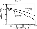
- 238000000113 differential scanning calorimetry Methods 0.000 description 4
- PPNKDDZCLDMRHS-UHFFFAOYSA-N dinitrooxybismuthanyl nitrate Chemical compound [Bi+3].[O-][N+]([O-])=O.[O-][N+]([O-])=O.[O-][N+]([O-])=O PPNKDDZCLDMRHS-UHFFFAOYSA-N 0.000 description 4
- 239000007772 electrode material Substances 0.000 description 4
- 239000007788 liquid Substances 0.000 description 4
- PQXKHYXIUOZZFA-UHFFFAOYSA-M lithium fluoride Chemical compound [Li+].[F-] PQXKHYXIUOZZFA-UHFFFAOYSA-M 0.000 description 4
- QJGQUHMNIGDVPM-UHFFFAOYSA-N nitrogen group Chemical group [N] QJGQUHMNIGDVPM-UHFFFAOYSA-N 0.000 description 4
- 229920001343 polytetrafluoroethylene Polymers 0.000 description 4
- 239000004810 polytetrafluoroethylene Substances 0.000 description 4
- 229920002981 polyvinylidene fluoride Polymers 0.000 description 4
- ZYXWYDDFNXBTFO-UHFFFAOYSA-N tetrazolidine Chemical compound C1NNNN1 ZYXWYDDFNXBTFO-UHFFFAOYSA-N 0.000 description 4
- CBDKQYKMCICBOF-UHFFFAOYSA-N thiazoline Chemical compound C1CN=CS1 CBDKQYKMCICBOF-UHFFFAOYSA-N 0.000 description 4
- BQCIDUSAKPWEOX-UHFFFAOYSA-N 1,1-Difluoroethene Chemical compound FC(F)=C BQCIDUSAKPWEOX-UHFFFAOYSA-N 0.000 description 3
- NZJIDBUDNBDSIH-UHFFFAOYSA-N 2-nitrosoethenylideneazanide Chemical compound O=N[CH-]C#N NZJIDBUDNBDSIH-UHFFFAOYSA-N 0.000 description 3
- WEVYAHXRMPXWCK-UHFFFAOYSA-N Acetonitrile Chemical compound CC#N WEVYAHXRMPXWCK-UHFFFAOYSA-N 0.000 description 3
- 229920000049 Carbon (fiber) Polymers 0.000 description 3
- RTZKZFJDLAIYFH-UHFFFAOYSA-N Diethyl ether Chemical compound CCOCC RTZKZFJDLAIYFH-UHFFFAOYSA-N 0.000 description 3
- 229910006309 Li—Mg Inorganic materials 0.000 description 3
- 229910019064 Mg-Si Inorganic materials 0.000 description 3
- 229910019406 Mg—Si Inorganic materials 0.000 description 3
- MKYBYDHXWVHEJW-UHFFFAOYSA-N N-[1-oxo-1-(2,4,6,7-tetrahydrotriazolo[4,5-c]pyridin-5-yl)propan-2-yl]-2-[[3-(trifluoromethoxy)phenyl]methylamino]pyrimidine-5-carboxamide Chemical compound O=C(C(C)NC(=O)C=1C=NC(=NC=1)NCC1=CC(=CC=C1)OC(F)(F)F)N1CC2=C(CC1)NN=N2 MKYBYDHXWVHEJW-UHFFFAOYSA-N 0.000 description 3
- 241000209094 Oryza Species 0.000 description 3
- 235000007164 Oryza sativa Nutrition 0.000 description 3
- HEMHJVSKTPXQMS-UHFFFAOYSA-M Sodium hydroxide Chemical compound [OH-].[Na+] HEMHJVSKTPXQMS-UHFFFAOYSA-M 0.000 description 3
- 229910009819 Ti3C2 Inorganic materials 0.000 description 3
- YXFVVABEGXRONW-UHFFFAOYSA-N Toluene Chemical compound CC1=CC=CC=C1 YXFVVABEGXRONW-UHFFFAOYSA-N 0.000 description 3
- JAWMENYCRQKKJY-UHFFFAOYSA-N [3-(2,4,6,7-tetrahydrotriazolo[4,5-c]pyridin-5-ylmethyl)-1-oxa-2,8-diazaspiro[4.5]dec-2-en-8-yl]-[2-[[3-(trifluoromethoxy)phenyl]methylamino]pyrimidin-5-yl]methanone Chemical compound N1N=NC=2CN(CCC=21)CC1=NOC2(C1)CCN(CC2)C(=O)C=1C=NC(=NC=1)NCC1=CC(=CC=C1)OC(F)(F)F JAWMENYCRQKKJY-UHFFFAOYSA-N 0.000 description 3
- PNEYBMLMFCGWSK-UHFFFAOYSA-N aluminium oxide Inorganic materials [O-2].[O-2].[O-2].[Al+3].[Al+3] PNEYBMLMFCGWSK-UHFFFAOYSA-N 0.000 description 3
- 235000013339 cereals Nutrition 0.000 description 3
- 229910052681 coesite Inorganic materials 0.000 description 3
- 229910052593 corundum Inorganic materials 0.000 description 3
- 229910052906 cristobalite Inorganic materials 0.000 description 3
- 239000011888 foil Substances 0.000 description 3
- 229910052742 iron Inorganic materials 0.000 description 3
- VNWKTOKETHGBQD-UHFFFAOYSA-N methane Chemical compound C VNWKTOKETHGBQD-UHFFFAOYSA-N 0.000 description 3
- 239000011259 mixed solution Substances 0.000 description 3
- LNOPIUAQISRISI-UHFFFAOYSA-N n'-hydroxy-2-propan-2-ylsulfonylethanimidamide Chemical compound CC(C)S(=O)(=O)CC(N)=NO LNOPIUAQISRISI-UHFFFAOYSA-N 0.000 description 3
- VLKZOEOYAKHREP-UHFFFAOYSA-N n-Hexane Chemical compound CCCCCC VLKZOEOYAKHREP-UHFFFAOYSA-N 0.000 description 3
- OOFGXDQWDNJDIS-UHFFFAOYSA-N oxathiolane Chemical compound C1COSC1 OOFGXDQWDNJDIS-UHFFFAOYSA-N 0.000 description 3
- GWLJTAJEHRYMCA-UHFFFAOYSA-N phospholane Chemical compound C1CCPC1 GWLJTAJEHRYMCA-UHFFFAOYSA-N 0.000 description 3
- 235000009566 rice Nutrition 0.000 description 3
- 239000000377 silicon dioxide Substances 0.000 description 3
- 229910052682 stishovite Inorganic materials 0.000 description 3
- 229910052905 tridymite Inorganic materials 0.000 description 3
- 229910001845 yogo sapphire Inorganic materials 0.000 description 3
- OHVLMTFVQDZYHP-UHFFFAOYSA-N 1-(2,4,6,7-tetrahydrotriazolo[4,5-c]pyridin-5-yl)-2-[4-[2-[[3-(trifluoromethoxy)phenyl]methylamino]pyrimidin-5-yl]piperazin-1-yl]ethanone Chemical compound N1N=NC=2CN(CCC=21)C(CN1CCN(CC1)C=1C=NC(=NC=1)NCC1=CC(=CC=C1)OC(F)(F)F)=O OHVLMTFVQDZYHP-UHFFFAOYSA-N 0.000 description 2
- KZEVSDGEBAJOTK-UHFFFAOYSA-N 1-(2,4,6,7-tetrahydrotriazolo[4,5-c]pyridin-5-yl)-2-[5-[2-[[3-(trifluoromethoxy)phenyl]methylamino]pyrimidin-5-yl]-1,3,4-oxadiazol-2-yl]ethanone Chemical compound N1N=NC=2CN(CCC=21)C(CC=1OC(=NN=1)C=1C=NC(=NC=1)NCC1=CC(=CC=C1)OC(F)(F)F)=O KZEVSDGEBAJOTK-UHFFFAOYSA-N 0.000 description 2
- HMUNWXXNJPVALC-UHFFFAOYSA-N 1-[4-[2-(2,3-dihydro-1H-inden-2-ylamino)pyrimidin-5-yl]piperazin-1-yl]-2-(2,4,6,7-tetrahydrotriazolo[4,5-c]pyridin-5-yl)ethanone Chemical compound C1C(CC2=CC=CC=C12)NC1=NC=C(C=N1)N1CCN(CC1)C(CN1CC2=C(CC1)NN=N2)=O HMUNWXXNJPVALC-UHFFFAOYSA-N 0.000 description 2
- LDXJRKWFNNFDSA-UHFFFAOYSA-N 2-(2,4,6,7-tetrahydrotriazolo[4,5-c]pyridin-5-yl)-1-[4-[2-[[3-(trifluoromethoxy)phenyl]methylamino]pyrimidin-5-yl]piperazin-1-yl]ethanone Chemical compound C1CN(CC2=NNN=C21)CC(=O)N3CCN(CC3)C4=CN=C(N=C4)NCC5=CC(=CC=C5)OC(F)(F)F LDXJRKWFNNFDSA-UHFFFAOYSA-N 0.000 description 2
- JQMFQLVAJGZSQS-UHFFFAOYSA-N 2-[4-[2-(2,3-dihydro-1H-inden-2-ylamino)pyrimidin-5-yl]piperazin-1-yl]-N-(2-oxo-3H-1,3-benzoxazol-6-yl)acetamide Chemical compound C1C(CC2=CC=CC=C12)NC1=NC=C(C=N1)N1CCN(CC1)CC(=O)NC1=CC2=C(NC(O2)=O)C=C1 JQMFQLVAJGZSQS-UHFFFAOYSA-N 0.000 description 2
- IHCCLXNEEPMSIO-UHFFFAOYSA-N 2-[4-[2-(2,3-dihydro-1H-inden-2-ylamino)pyrimidin-5-yl]piperidin-1-yl]-1-(2,4,6,7-tetrahydrotriazolo[4,5-c]pyridin-5-yl)ethanone Chemical compound C1C(CC2=CC=CC=C12)NC1=NC=C(C=N1)C1CCN(CC1)CC(=O)N1CC2=C(CC1)NN=N2 IHCCLXNEEPMSIO-UHFFFAOYSA-N 0.000 description 2
- JVKRKMWZYMKVTQ-UHFFFAOYSA-N 2-[4-[2-(2,3-dihydro-1H-inden-2-ylamino)pyrimidin-5-yl]pyrazol-1-yl]-N-(2-oxo-3H-1,3-benzoxazol-6-yl)acetamide Chemical compound C1C(CC2=CC=CC=C12)NC1=NC=C(C=N1)C=1C=NN(C=1)CC(=O)NC1=CC2=C(NC(O2)=O)C=C1 JVKRKMWZYMKVTQ-UHFFFAOYSA-N 0.000 description 2
- WTFUTSCZYYCBAY-SXBRIOAWSA-N 6-[(E)-C-[[4-[2-(2,3-dihydro-1H-inden-2-ylamino)pyrimidin-5-yl]piperazin-1-yl]methyl]-N-hydroxycarbonimidoyl]-3H-1,3-benzoxazol-2-one Chemical compound C1C(CC2=CC=CC=C12)NC1=NC=C(C=N1)N1CCN(CC1)C/C(=N/O)/C1=CC2=C(NC(O2)=O)C=C1 WTFUTSCZYYCBAY-SXBRIOAWSA-N 0.000 description 2
- DFGKGUXTPFWHIX-UHFFFAOYSA-N 6-[2-[4-[2-(2,3-dihydro-1H-inden-2-ylamino)pyrimidin-5-yl]piperazin-1-yl]acetyl]-3H-1,3-benzoxazol-2-one Chemical compound C1C(CC2=CC=CC=C12)NC1=NC=C(C=N1)N1CCN(CC1)CC(=O)C1=CC2=C(NC(O2)=O)C=C1 DFGKGUXTPFWHIX-UHFFFAOYSA-N 0.000 description 2
- OIFBSDVPJOWBCH-UHFFFAOYSA-N Diethyl carbonate Chemical compound CCOC(=O)OCC OIFBSDVPJOWBCH-UHFFFAOYSA-N 0.000 description 2
- LFQSCWFLJHTTHZ-UHFFFAOYSA-N Ethanol Chemical compound CCO LFQSCWFLJHTTHZ-UHFFFAOYSA-N 0.000 description 2
- 229910000927 Ge alloy Inorganic materials 0.000 description 2
- DGAQECJNVWCQMB-PUAWFVPOSA-M Ilexoside XXIX Chemical compound C[C@@H]1CC[C@@]2(CC[C@@]3(C(=CC[C@H]4[C@]3(CC[C@@H]5[C@@]4(CC[C@@H](C5(C)C)OS(=O)(=O)[O-])C)C)[C@@H]2[C@]1(C)O)C)C(=O)O[C@H]6[C@@H]([C@H]([C@@H]([C@H](O6)CO)O)O)O.[Na+] DGAQECJNVWCQMB-PUAWFVPOSA-M 0.000 description 2
- 229910002651 NO3 Inorganic materials 0.000 description 2
- PXHVJJICTQNCMI-UHFFFAOYSA-N Nickel Chemical compound [Ni] PXHVJJICTQNCMI-UHFFFAOYSA-N 0.000 description 2
- 239000008118 PEG 6000 Substances 0.000 description 2
- 229920002584 Polyethylene Glycol 6000 Polymers 0.000 description 2
- ZLMJMSJWJFRBEC-UHFFFAOYSA-N Potassium Chemical compound [K] ZLMJMSJWJFRBEC-UHFFFAOYSA-N 0.000 description 2
- XUIMIQQOPSSXEZ-UHFFFAOYSA-N Silicon Chemical compound [Si] XUIMIQQOPSSXEZ-UHFFFAOYSA-N 0.000 description 2
- YTPLMLYBLZKORZ-UHFFFAOYSA-N Thiophene Chemical compound C=1C=CSC=1 YTPLMLYBLZKORZ-UHFFFAOYSA-N 0.000 description 2
- 229910009818 Ti3AlC2 Inorganic materials 0.000 description 2
- HCHKCACWOHOZIP-UHFFFAOYSA-N Zinc Chemical compound [Zn] HCHKCACWOHOZIP-UHFFFAOYSA-N 0.000 description 2
- MKPXGEVFQSIKGE-UHFFFAOYSA-N [Mg].[Si] Chemical compound [Mg].[Si] MKPXGEVFQSIKGE-UHFFFAOYSA-N 0.000 description 2
- BRCWHGIUHLWZBK-UHFFFAOYSA-K bismuth;trifluoride Chemical compound F[Bi](F)F BRCWHGIUHLWZBK-UHFFFAOYSA-K 0.000 description 2
- 239000003990 capacitor Substances 0.000 description 2
- 239000004917 carbon fiber Substances 0.000 description 2
- 238000001816 cooling Methods 0.000 description 2
- 239000011889 copper foil Substances 0.000 description 2
- MTHSVFCYNBDYFN-UHFFFAOYSA-N diethylene glycol Chemical compound OCCOCCO MTHSVFCYNBDYFN-UHFFFAOYSA-N 0.000 description 2
- 229910001873 dinitrogen Inorganic materials 0.000 description 2
- VUPKGFBOKBGHFZ-UHFFFAOYSA-N dipropyl carbonate Chemical compound CCCOC(=O)OCCC VUPKGFBOKBGHFZ-UHFFFAOYSA-N 0.000 description 2
- 238000007599 discharging Methods 0.000 description 2
- 238000007606 doctor blade method Methods 0.000 description 2
- JBTWLSYIZRCDFO-UHFFFAOYSA-N ethyl methyl carbonate Chemical compound CCOC(=O)OC JBTWLSYIZRCDFO-UHFFFAOYSA-N 0.000 description 2
- CYEDOLFRAIXARV-UHFFFAOYSA-N ethyl propyl carbonate Chemical compound CCCOC(=O)OCC CYEDOLFRAIXARV-UHFFFAOYSA-N 0.000 description 2
- 239000007789 gas Substances 0.000 description 2
- AMXOYNBUYSYVKV-UHFFFAOYSA-M lithium bromide Chemical compound [Li+].[Br-] AMXOYNBUYSYVKV-UHFFFAOYSA-M 0.000 description 2
- XGZVUEUWXADBQD-UHFFFAOYSA-L lithium carbonate Chemical compound [Li+].[Li+].[O-]C([O-])=O XGZVUEUWXADBQD-UHFFFAOYSA-L 0.000 description 2
- 229910052808 lithium carbonate Inorganic materials 0.000 description 2
- 230000014759 maintenance of location Effects 0.000 description 2
- KKQAVHGECIBFRQ-UHFFFAOYSA-N methyl propyl carbonate Chemical compound CCCOC(=O)OC KKQAVHGECIBFRQ-UHFFFAOYSA-N 0.000 description 2
- PVMUVDSEICYOMA-UHFFFAOYSA-N n-chlorosulfonylsulfamoyl chloride Chemical compound ClS(=O)(=O)NS(Cl)(=O)=O PVMUVDSEICYOMA-UHFFFAOYSA-N 0.000 description 2
- 239000002135 nanosheet Substances 0.000 description 2
- 230000007935 neutral effect Effects 0.000 description 2
- 229920000642 polymer Polymers 0.000 description 2
- 229910021426 porous silicon Inorganic materials 0.000 description 2
- 239000011591 potassium Substances 0.000 description 2
- 229910052700 potassium Inorganic materials 0.000 description 2
- 239000011347 resin Substances 0.000 description 2
- 229920005989 resin Polymers 0.000 description 2
- 239000011734 sodium Substances 0.000 description 2
- 229910052708 sodium Inorganic materials 0.000 description 2
- YLQBMQCUIZJEEH-UHFFFAOYSA-N tetrahydrofuran Natural products C=1C=COC=1 YLQBMQCUIZJEEH-UHFFFAOYSA-N 0.000 description 2
- 229910052725 zinc Inorganic materials 0.000 description 2
- 239000011701 zinc Substances 0.000 description 2
- ONDPHDOFVYQSGI-UHFFFAOYSA-N zinc nitrate Chemical compound [Zn+2].[O-][N+]([O-])=O.[O-][N+]([O-])=O ONDPHDOFVYQSGI-UHFFFAOYSA-N 0.000 description 2
- KEQGZUUPPQEDPF-UHFFFAOYSA-N 1,3-dichloro-5,5-dimethylimidazolidine-2,4-dione Chemical compound CC1(C)N(Cl)C(=O)N(Cl)C1=O KEQGZUUPPQEDPF-UHFFFAOYSA-N 0.000 description 1
- VFWCMGCRMGJXDK-UHFFFAOYSA-N 1-chlorobutane Chemical compound CCCCCl VFWCMGCRMGJXDK-UHFFFAOYSA-N 0.000 description 1
- VXZBYIWNGKSFOJ-UHFFFAOYSA-N 2-[4-[5-(2,3-dihydro-1H-inden-2-ylamino)pyrazin-2-yl]pyrazol-1-yl]-1-(2,4,6,7-tetrahydrotriazolo[4,5-c]pyridin-5-yl)ethanone Chemical compound C1C(CC2=CC=CC=C12)NC=1N=CC(=NC=1)C=1C=NN(C=1)CC(=O)N1CC2=C(CC1)NN=N2 VXZBYIWNGKSFOJ-UHFFFAOYSA-N 0.000 description 1
- JZDMKXPFPHBPKJ-UHFFFAOYSA-N 2-nitroethenylideneazanide Chemical compound [O-][N+]([O-])=CC#N JZDMKXPFPHBPKJ-UHFFFAOYSA-N 0.000 description 1
- 229910001152 Bi alloy Inorganic materials 0.000 description 1
- BVKZGUZCCUSVTD-UHFFFAOYSA-L Carbonate Chemical compound [O-]C([O-])=O BVKZGUZCCUSVTD-UHFFFAOYSA-L 0.000 description 1
- 229920002134 Carboxymethyl cellulose Polymers 0.000 description 1
- 229910000733 Li alloy Inorganic materials 0.000 description 1
- 229910010941 LiFSI Inorganic materials 0.000 description 1
- HBBGRARXTFLTSG-UHFFFAOYSA-N Lithium ion Chemical compound [Li+] HBBGRARXTFLTSG-UHFFFAOYSA-N 0.000 description 1
- 229910000861 Mg alloy Inorganic materials 0.000 description 1
- 229910001182 Mo alloy Inorganic materials 0.000 description 1
- OAICVXFJPJFONN-UHFFFAOYSA-N Phosphorus Chemical compound [P] OAICVXFJPJFONN-UHFFFAOYSA-N 0.000 description 1
- 229920003171 Poly (ethylene oxide) Polymers 0.000 description 1
- BQCADISMDOOEFD-UHFFFAOYSA-N Silver Chemical compound [Ag] BQCADISMDOOEFD-UHFFFAOYSA-N 0.000 description 1
- UCKMPCXJQFINFW-UHFFFAOYSA-N Sulphide Chemical compound [S-2] UCKMPCXJQFINFW-UHFFFAOYSA-N 0.000 description 1
- 239000006230 acetylene black Substances 0.000 description 1
- 239000000654 additive Substances 0.000 description 1
- 230000000996 additive effect Effects 0.000 description 1
- 239000007864 aqueous solution Substances 0.000 description 1
- HRYZWHHZPQKTII-UHFFFAOYSA-N chloroethane Chemical compound CCCl HRYZWHHZPQKTII-UHFFFAOYSA-N 0.000 description 1
- 239000010941 cobalt Substances 0.000 description 1
- 229910017052 cobalt Inorganic materials 0.000 description 1
- GUTLYIVDDKVIGB-UHFFFAOYSA-N cobalt atom Chemical compound [Co] GUTLYIVDDKVIGB-UHFFFAOYSA-N 0.000 description 1
- 239000013065 commercial product Substances 0.000 description 1
- 230000000295 complement effect Effects 0.000 description 1
- XTVVROIMIGLXTD-UHFFFAOYSA-N copper(II) nitrate Chemical compound [Cu+2].[O-][N+]([O-])=O.[O-][N+]([O-])=O XTVVROIMIGLXTD-UHFFFAOYSA-N 0.000 description 1
- IEJIGPNLZYLLBP-UHFFFAOYSA-N dimethyl carbonate Chemical compound COC(=O)OC IEJIGPNLZYLLBP-UHFFFAOYSA-N 0.000 description 1
- 238000001035 drying Methods 0.000 description 1
- 230000000694 effects Effects 0.000 description 1
- 238000005516 engineering process Methods 0.000 description 1
- 229960003750 ethyl chloride Drugs 0.000 description 1
- 238000011156 evaluation Methods 0.000 description 1
- 239000002360 explosive Substances 0.000 description 1
- 239000001989 lithium alloy Substances 0.000 description 1
- HSZCZNFXUDYRKD-UHFFFAOYSA-M lithium iodide Inorganic materials [Li+].[I-] HSZCZNFXUDYRKD-UHFFFAOYSA-M 0.000 description 1
- 229910001416 lithium ion Inorganic materials 0.000 description 1
- FUJCRWPEOMXPAD-UHFFFAOYSA-N lithium oxide Chemical compound [Li+].[Li+].[O-2] FUJCRWPEOMXPAD-UHFFFAOYSA-N 0.000 description 1
- 229910001947 lithium oxide Inorganic materials 0.000 description 1
- VDVLPSWVDYJFRW-UHFFFAOYSA-N lithium;bis(fluorosulfonyl)azanide Chemical compound [Li+].FS(=O)(=O)[N-]S(F)(=O)=O VDVLPSWVDYJFRW-UHFFFAOYSA-N 0.000 description 1
- WPBNNNQJVZRUHP-UHFFFAOYSA-L manganese(2+);methyl n-[[2-(methoxycarbonylcarbamothioylamino)phenyl]carbamothioyl]carbamate;n-[2-(sulfidocarbothioylamino)ethyl]carbamodithioate Chemical compound [Mn+2].[S-]C(=S)NCCNC([S-])=S.COC(=O)NC(=S)NC1=CC=CC=C1NC(=S)NC(=O)OC WPBNNNQJVZRUHP-UHFFFAOYSA-L 0.000 description 1
- 150000002739 metals Chemical class 0.000 description 1
- 238000012986 modification Methods 0.000 description 1
- 230000004048 modification Effects 0.000 description 1
- KTQDYGVEEFGIIL-UHFFFAOYSA-N n-fluorosulfonylsulfamoyl fluoride Chemical compound FS(=O)(=O)NS(F)(=O)=O KTQDYGVEEFGIIL-UHFFFAOYSA-N 0.000 description 1
- SNMVRZFUUCLYTO-UHFFFAOYSA-N n-propyl chloride Chemical compound CCCCl SNMVRZFUUCLYTO-UHFFFAOYSA-N 0.000 description 1
- 229910052759 nickel Inorganic materials 0.000 description 1
- 239000012299 nitrogen atmosphere Substances 0.000 description 1
- 229910052698 phosphorus Inorganic materials 0.000 description 1
- 239000011574 phosphorus Substances 0.000 description 1
- 229920000058 polyacrylate Polymers 0.000 description 1
- 238000002360 preparation method Methods 0.000 description 1
- 239000000047 product Substances 0.000 description 1
- 239000000376 reactant Substances 0.000 description 1
- 150000003377 silicon compounds Chemical class 0.000 description 1
- 239000002210 silicon-based material Substances 0.000 description 1
- 229910052709 silver Inorganic materials 0.000 description 1
- 239000004332 silver Substances 0.000 description 1
- 235000011121 sodium hydroxide Nutrition 0.000 description 1
- 239000010935 stainless steel Substances 0.000 description 1
- 229910001220 stainless steel Inorganic materials 0.000 description 1
- 229920003048 styrene butadiene rubber Polymers 0.000 description 1
- 239000000758 substrate Substances 0.000 description 1
- 238000009210 therapy by ultrasound Methods 0.000 description 1
- 229930192474 thiophene Natural products 0.000 description 1
- 239000002341 toxic gas Substances 0.000 description 1
- 238000005406 washing Methods 0.000 description 1
Images


Classifications
-
- H—ELECTRICITY
- H01—ELECTRIC ELEMENTS
- H01M—PROCESSES OR MEANS, e.g. BATTERIES, FOR THE DIRECT CONVERSION OF CHEMICAL ENERGY INTO ELECTRICAL ENERGY
- H01M4/00—Electrodes
- H01M4/02—Electrodes composed of, or comprising, active material
- H01M4/64—Carriers or collectors
- H01M4/66—Selection of materials
-
- C—CHEMISTRY; METALLURGY
- C01—INORGANIC CHEMISTRY
- C01B—NON-METALLIC ELEMENTS; COMPOUNDS THEREOF; METALLOIDS OR COMPOUNDS THEREOF NOT COVERED BY SUBCLASS C01C
- C01B25/00—Phosphorus; Compounds thereof
- C01B25/16—Oxyacids of phosphorus; Salts thereof
- C01B25/26—Phosphates
- C01B25/37—Phosphates of heavy metals
- C01B25/375—Phosphates of heavy metals of iron
-
- H—ELECTRICITY
- H01—ELECTRIC ELEMENTS
- H01M—PROCESSES OR MEANS, e.g. BATTERIES, FOR THE DIRECT CONVERSION OF CHEMICAL ENERGY INTO ELECTRICAL ENERGY
- H01M10/00—Secondary cells; Manufacture thereof
- H01M10/05—Accumulators with non-aqueous electrolyte
- H01M10/052—Li-accumulators
-
- H—ELECTRICITY
- H01—ELECTRIC ELEMENTS
- H01M—PROCESSES OR MEANS, e.g. BATTERIES, FOR THE DIRECT CONVERSION OF CHEMICAL ENERGY INTO ELECTRICAL ENERGY
- H01M10/00—Secondary cells; Manufacture thereof
- H01M10/05—Accumulators with non-aqueous electrolyte
- H01M10/052—Li-accumulators
- H01M10/0525—Rocking-chair batteries, i.e. batteries with lithium insertion or intercalation in both electrodes; Lithium-ion batteries
-
- H—ELECTRICITY
- H01—ELECTRIC ELEMENTS
- H01M—PROCESSES OR MEANS, e.g. BATTERIES, FOR THE DIRECT CONVERSION OF CHEMICAL ENERGY INTO ELECTRICAL ENERGY
- H01M10/00—Secondary cells; Manufacture thereof
- H01M10/05—Accumulators with non-aqueous electrolyte
- H01M10/056—Accumulators with non-aqueous electrolyte characterised by the materials used as electrolytes, e.g. mixed inorganic/organic electrolytes
- H01M10/0561—Accumulators with non-aqueous electrolyte characterised by the materials used as electrolytes, e.g. mixed inorganic/organic electrolytes the electrolyte being constituted of inorganic materials only
- H01M10/0562—Solid materials
-
- H—ELECTRICITY
- H01—ELECTRIC ELEMENTS
- H01M—PROCESSES OR MEANS, e.g. BATTERIES, FOR THE DIRECT CONVERSION OF CHEMICAL ENERGY INTO ELECTRICAL ENERGY
- H01M10/00—Secondary cells; Manufacture thereof
- H01M10/05—Accumulators with non-aqueous electrolyte
- H01M10/056—Accumulators with non-aqueous electrolyte characterised by the materials used as electrolytes, e.g. mixed inorganic/organic electrolytes
- H01M10/0564—Accumulators with non-aqueous electrolyte characterised by the materials used as electrolytes, e.g. mixed inorganic/organic electrolytes the electrolyte being constituted of organic materials only
-
- H—ELECTRICITY
- H01—ELECTRIC ELEMENTS
- H01M—PROCESSES OR MEANS, e.g. BATTERIES, FOR THE DIRECT CONVERSION OF CHEMICAL ENERGY INTO ELECTRICAL ENERGY
- H01M4/00—Electrodes
- H01M4/02—Electrodes composed of, or comprising, active material
- H01M4/04—Processes of manufacture in general
- H01M4/0402—Methods of deposition of the material
- H01M4/0407—Methods of deposition of the material by coating on an electrolyte layer
-
- H—ELECTRICITY
- H01—ELECTRIC ELEMENTS
- H01M—PROCESSES OR MEANS, e.g. BATTERIES, FOR THE DIRECT CONVERSION OF CHEMICAL ENERGY INTO ELECTRICAL ENERGY
- H01M4/00—Electrodes
- H01M4/02—Electrodes composed of, or comprising, active material
- H01M4/13—Electrodes for accumulators with non-aqueous electrolyte, e.g. for lithium-accumulators; Processes of manufacture thereof
- H01M4/134—Electrodes based on metals, Si or alloys
-
- H—ELECTRICITY
- H01—ELECTRIC ELEMENTS
- H01M—PROCESSES OR MEANS, e.g. BATTERIES, FOR THE DIRECT CONVERSION OF CHEMICAL ENERGY INTO ELECTRICAL ENERGY
- H01M4/00—Electrodes
- H01M4/02—Electrodes composed of, or comprising, active material
- H01M4/13—Electrodes for accumulators with non-aqueous electrolyte, e.g. for lithium-accumulators; Processes of manufacture thereof
- H01M4/139—Processes of manufacture
- H01M4/1395—Processes of manufacture of electrodes based on metals, Si or alloys
-
- H—ELECTRICITY
- H01—ELECTRIC ELEMENTS
- H01M—PROCESSES OR MEANS, e.g. BATTERIES, FOR THE DIRECT CONVERSION OF CHEMICAL ENERGY INTO ELECTRICAL ENERGY
- H01M4/00—Electrodes
- H01M4/02—Electrodes composed of, or comprising, active material
- H01M4/36—Selection of substances as active materials, active masses, active liquids
- H01M4/362—Composites
- H01M4/366—Composites as layered products
-
- H—ELECTRICITY
- H01—ELECTRIC ELEMENTS
- H01M—PROCESSES OR MEANS, e.g. BATTERIES, FOR THE DIRECT CONVERSION OF CHEMICAL ENERGY INTO ELECTRICAL ENERGY
- H01M4/00—Electrodes
- H01M4/02—Electrodes composed of, or comprising, active material
- H01M4/36—Selection of substances as active materials, active masses, active liquids
- H01M4/38—Selection of substances as active materials, active masses, active liquids of elements or alloys
-
- H—ELECTRICITY
- H01—ELECTRIC ELEMENTS
- H01M—PROCESSES OR MEANS, e.g. BATTERIES, FOR THE DIRECT CONVERSION OF CHEMICAL ENERGY INTO ELECTRICAL ENERGY
- H01M4/00—Electrodes
- H01M4/02—Electrodes composed of, or comprising, active material
- H01M4/62—Selection of inactive substances as ingredients for active masses, e.g. binders, fillers
-
- H—ELECTRICITY
- H01—ELECTRIC ELEMENTS
- H01M—PROCESSES OR MEANS, e.g. BATTERIES, FOR THE DIRECT CONVERSION OF CHEMICAL ENERGY INTO ELECTRICAL ENERGY
- H01M4/00—Electrodes
- H01M4/02—Electrodes composed of, or comprising, active material
- H01M4/64—Carriers or collectors
- H01M4/66—Selection of materials
- H01M4/661—Metal or alloys, e.g. alloy coatings
-
- H—ELECTRICITY
- H01—ELECTRIC ELEMENTS
- H01M—PROCESSES OR MEANS, e.g. BATTERIES, FOR THE DIRECT CONVERSION OF CHEMICAL ENERGY INTO ELECTRICAL ENERGY
- H01M4/00—Electrodes
- H01M4/02—Electrodes composed of, or comprising, active material
- H01M4/64—Carriers or collectors
- H01M4/70—Carriers or collectors characterised by shape or form
- H01M4/72—Grids
- H01M4/74—Meshes or woven material; Expanded metal
-
- C—CHEMISTRY; METALLURGY
- C01—INORGANIC CHEMISTRY
- C01P—INDEXING SCHEME RELATING TO STRUCTURAL AND PHYSICAL ASPECTS OF SOLID INORGANIC COMPOUNDS
- C01P2002/00—Crystal-structural characteristics
- C01P2002/50—Solid solutions
- C01P2002/52—Solid solutions containing elements as dopants
- C01P2002/54—Solid solutions containing elements as dopants one element only
-
- C—CHEMISTRY; METALLURGY
- C01—INORGANIC CHEMISTRY
- C01P—INDEXING SCHEME RELATING TO STRUCTURAL AND PHYSICAL ASPECTS OF SOLID INORGANIC COMPOUNDS
- C01P2002/00—Crystal-structural characteristics
- C01P2002/70—Crystal-structural characteristics defined by measured X-ray, neutron or electron diffraction data
- C01P2002/74—Crystal-structural characteristics defined by measured X-ray, neutron or electron diffraction data by peak-intensities or a ratio thereof only
-
- H—ELECTRICITY
- H01—ELECTRIC ELEMENTS
- H01M—PROCESSES OR MEANS, e.g. BATTERIES, FOR THE DIRECT CONVERSION OF CHEMICAL ENERGY INTO ELECTRICAL ENERGY
- H01M4/00—Electrodes
- H01M4/02—Electrodes composed of, or comprising, active material
- H01M2004/026—Electrodes composed of, or comprising, active material characterised by the polarity
- H01M2004/027—Negative electrodes
-
- H—ELECTRICITY
- H01—ELECTRIC ELEMENTS
- H01M—PROCESSES OR MEANS, e.g. BATTERIES, FOR THE DIRECT CONVERSION OF CHEMICAL ENERGY INTO ELECTRICAL ENERGY
- H01M2300/00—Electrolytes
- H01M2300/0017—Non-aqueous electrolytes
- H01M2300/0065—Solid electrolytes
-
- Y—GENERAL TAGGING OF NEW TECHNOLOGICAL DEVELOPMENTS; GENERAL TAGGING OF CROSS-SECTIONAL TECHNOLOGIES SPANNING OVER SEVERAL SECTIONS OF THE IPC; TECHNICAL SUBJECTS COVERED BY FORMER USPC CROSS-REFERENCE ART COLLECTIONS [XRACs] AND DIGESTS
- Y02—TECHNOLOGIES OR APPLICATIONS FOR MITIGATION OR ADAPTATION AGAINST CLIMATE CHANGE
- Y02P—CLIMATE CHANGE MITIGATION TECHNOLOGIES IN THE PRODUCTION OR PROCESSING OF GOODS
- Y02P70/00—Climate change mitigation technologies in the production process for final industrial or consumer products
- Y02P70/50—Manufacturing or production processes characterised by the final manufactured product
Definitions
- the present application relates to an intermediate product of an electrode, an electrode using the same, an electrode pellet using the same, and a method for producing each thereof, and more particularly, to an intermediate product of an electrode, including a molten source, in which a second metal and a base particle on which a coating layer, including a first metal is formed are melted, an electrode using the same, an electrode pellet using the same, and a method for producing each thereof.
- the present application relates to an electrode powder, an electrode using the same, and a method for producing each thereof, and more particularly, to an electrode powder for a secondary battery, an electrode using the same, and a method for producing each thereof.
- Small IT devices such as smart phones took lead in initial growth of a global secondary battery market, but recently, a secondary battery market for vehicles is rapidly growing with the growth of an electric vehicle market.
- next-generation secondary batteries are also being actively developed to meet the safety issues of secondary batteries and the demand for increased battery capacity.
- Korean Patent Registration Publication No. 10-1788232 discloses an electrode for a secondary battery in which an electrode mixture including an electrode active material and a binder is coated on a current collector, and in which the electrode includes: a first electrode mixture layer which contains an electrode active material and a first binder having a glass transition temperature (Tg) lower than that of a second binder and is coated on the current collector; and a second electrode mixture layer which contains an electrode active material and a second binder having a glass transition temperature (Tg) higher than that of the first binder and is coated on the first electrode mixture layer, in which a glass transition temperature (Tg) of the first binder is 15°C or less; a glass transition temperature (Tg) of the second binder is 10°C or more in a range higher than the glass transition temperature of the first binder; the glass transition temperature (Tg) of the second binder is 10°C or more to less than 25°C in a range higher than the glass transition temperature of the first binder; the electrode for the secondary battery is a negative
- One technical object of the present application is to provide an intermediate product of an electrode, an electrode using the same, an electrode pellet using the same, and a method for producing each thereof.
- Another technical object of the present application is to provide an intermediate product of an electrode for a secondary battery capable of enhancing charge/discharge efficiency, an electrode using the same, an electrode pellet using the same, and a method for producing each thereof.
- Still another technical object of the present application is to provide an intermediate product of an electrode for a secondary battery having high stability and long life, an electrode using the same, an electrode pellet using the same, and a method for producing each thereof.
- Still another technical object of the present application is to provide an intermediate product of an electrode for an all-solid-state battery, an electrode using the same, an electrode pellet using the same, and a method for producing each thereof.
- Still another technical object of the present application is to provide an electrode powder, an electrode using the same, and a method for producing each thereof.
- Still another technical object of the present application is to provide an electrode powder for a secondary battery capable of enhancing charge/discharge efficiency, an electrode using the same, and a method for producing each thereof.
- Still another technical object of the present application is to provide an electrode powder for a secondary battery having high stability and long life, an electrode using the same, and a method for producing each thereof.
- Still another technical object of the present application is to provide an electrode powder for an all-solid-state battery, an electrode using the same, and a method for producing each thereof.
- the present application may provide a method for producing an intermediate product of an electrode.
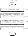
- the method for producing an intermediate product of an electrode may include: preparing a base particle; forming a coating layer, containing a first metal, on the surface of the base particle by mixing the base particle with a coating source which contains the first metal; and forming a molten source, in which a second metal and the base particle on which the coating layer is formed are melted by heat-treating the second metal and the base particle on which the coating layer is formed.
- the base particle may include a metal, a metal oxide, a metal carbide, or a carbon structure.
- the base particle may include a carbon structure
- the method for producing an intermediate product of an electrode may further include pretreating the base particle with a metal nitric acid solution before mixing the base particle with the coating source.
- the first metal and the second metal may include lithium.
- the coating source may include a compound of lithium, nitrogen, fluorine, sulfur, carbon, and oxygen.
- the base particle and the coating source may be heat-treated at a temperature higher than room temperature after being mixed.
- the present application may provide a method for producing an electrode.
- the method for producing an electrode may include preparing the molten source according to the above-described embodiment, and producing an electrode film by coating with the molten source.
- the present application may provide a method for producing an electrode pellet.
- the method for producing an electrode pellet may include preparing the molten source according to the above-described embodiment, and producing an electrode pellet by cooling and dividing the molten source.
- the present application may provide a method for producing a coating source.
- the method for producing a coating source may include: preparing a first precursor containing sulfur and chlorine, a second precursor containing sulfur and chlorine, and a third precursor containing sulfur and nitrogen; producing a first compound containing sulfur, chlorine, oxygen, nitrogen, and hydrogen by reacting the first precursor, the second precursor, and the third precursor; producing a second compound by reacting the first compound and a fourth precursor containing fluorine; and producing a third compound by reacting the second compound and a metal salt containing a first metal.
- the method for producing a coating source may further include: reacting the second compound with deionized water at a temperature lower than room temperature before reacting the second compound and the metal salt, and the producing of a third compound may include reacting the second compound, reacted with deionized water, with the metal salt.
- the first metal may include lithium, potassium, sodium, zinc, iron, magnesium, silicon, or aluminum.
- the present application may provide a method for producing an intermediate product of an electrode.
- the method for producing an intermediate product of an electrode may include: preparing the coating source according to the above-described embodiment; forming a coating layer, containing the first metal, on the surface of the base particle by mixing the base particle with the coating source; and forming a molten source, in which a second metal and the base particle on which the coating layer is formed are melted by heat-treating the second metal and the base particle on which the coating layer is formed.
- the present application may provide an electrode film or an electrode pellet.
- the electrode film or the electrode pellet may include one in which a molten source, in which a base particle and a coating layer provided on a surface of the base particle and containing a first metal are melted with a second metal, is coagulated.
- the base particle may include at least any one of silicon oxide, aluminum, aluminum oxide, copper, copper oxide, titanium, titanium oxide, titanium carbide, magnesium, tin, tin oxide, germanium, bismuth, molybdenum, or carbon structure.
- the present application may provide a negative electrode.
- the negative electrode may include a current collector and a negative electrode active material layer provided on the current collector, in which the negative electrode active material layer may include a lithium compound containing lithium and an anion bonded with the lithium, a conductive material having conductivity higher than that of the lithium compound, and a binder.
- a ratio of the lithium compound, the conductive material, and the binder may be 6:2:2 to 8:1:1 wt% in the negative electrode active material layer.
- the anion may include at least any one of NO 3 - , Cl - , Br - , FSI - , F - , or I - .
- the present application may provide a method for producing an electrode powder.
- the method for producing an electrode powder may include: preparing a silicon oxide; producing an intermediate compound by mixing and reacting the silicon oxide and a first metal; and producing an electrode powder containing at least the silicon among silicon and the first metal from the intermediate compound by providing a cleaning solution to the intermediate compound, in which a ratio of the first metal in the electrode powder is controlled depending on a molar concentration of the cleaning solution.
- the ratio of the first metal in the electrode powder may decrease, as a molar concentration of the cleaning solution increases.
- the electrode powder when the molar concentration of the cleaning solution is higher than a reference concentration, the electrode powder may not include the first metal, but include the silicon. When the molar concentration of the cleaning solution is lower than the reference concentration, the electrode powder may include an alloy powder of the silicon and the first metal.
- the electrode powder may have a three-dimensional structure.
- the preparing of a silicon oxide may include: preparing biomass containing grains or leaves thereof; heat-treating the biomass; and producing the silicon oxide having a three-dimensional structure by providing an acidic solution to the heat-treated biomass.
- the silicon oxide and the first metal may be heat-treated in an inert gas atmosphere to form the intermediate compound.
- the present application may provide a negative electrode.
- the negative electrode may include the electrode powder produced by the production method according to the above-described embodiment, a conductive material having conductivity higher than that of the electrode powder, and a binder.
- the negative electrode may include silicon which is produced from grains or leaves thereof and has a three-dimensional structure.
- the negative electrode may further include magnesium alloyed with the silicon to have a three-dimensional structure.
- the method for producing an intermediate product of an electrode may include: forming a coating layer, containing a first metal, on the surface of a base particle by mixing the base particle with a coating source which contains the first metal; and producing a molten source, in which a second metal and the base particle on which the coating layer is formed are melted by heat-treating the second metal and the base particle on which the coating layer is formed.
- the molten source may be an intermediate product for producing an electrode, in which an electrode film or an electrode pellet may be produced from the molten source. Accordingly, the element included in the base particle, the first metal, and the second metal can have a substantially uniform alloy composition in the molten source, the electrode film, and the electrode pellet, thereby enhancing the charge/discharge properties, lifespan, and stability of a secondary battery including the electrode film.
- a negative electrode active material layer can be formed by coating a coating source including a lithium compound in a powder state on a current collector. Accordingly, a ratio of the lithium compound in the negative electrode including the negative electrode active material layer and the current collector can be easily controlled and the negative electrode can be produced by a simple process. Accordingly, the negative electrode and the production method thereof with a less production cost and an easy mass production can be provided.
- an intermediate compound can be produced by reacting a silicon oxide having a three-dimensional structure and a first metal, and an electrode powder having a three-dimensional structure can be produced by providing a cleansing solution to the intermediate compound.
- the silicon oxide having a three-dimensional structure can be produced by using biomass. Accordingly, a process of producing the electrode powder capable of producing an electrode for a secondary battery may be simplified with a less production cost and time.
- first element When it is mentioned in the specification that one element is on another element, it means that the first element may be directly formed on the second element or a third element may be interposed between the first element and the second element. Further, in the drawings, the thicknesses of the membrane and areas are exaggerated for efficient description of the technical contents.
- first, second, and third are used to describe various elements, but the elements are not limited to the terms. These terms are used only to distinguish one component from another component. Accordingly, an element mentioned as a first element in one embodiment may be mentioned as a second element in another embodiment.
- the embodiments described and illustrated herein also include their complementary embodiments. Further, the term "and/or" in the specification is used to include at least one of the elements enumerated in the specification.
- an intermediate product of an electrode, an electrode using the same, an electrode pellet using the same, and a method for producing each thereof will be described.
- FIG. 1 is a flowchart for explaining a method of producing an intermediate product of an electrode according to a first embodiment of the present application, and an electrode film and an electrode pellet using the same
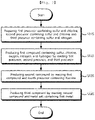
- FIG. 2 is a flowchart for explaining a method of producing a coating source used in a process of producing an intermediate product of an electrode according to a first embodiment of the present application
- FIG. 3 is a view for explaining a coating layer and a base particle produced according to a method for producing an intermediate product of an electrode according to a first embodiment of the present application.
- a base particle 100 may be prepared (S110).
- the base particle 100 may include a metal, a metal oxide, a metal carbide, or a carbon structure.
- the base particle 100 may include at least any one of silicon oxide, aluminum, aluminum oxide, copper, copper oxide, titanium, titanium oxide, titanium carbide, magnesium, tin, tin oxide, germanium, bismuth, or molybdenum.
- the carbon structure may be carbon fiber, carbon fabric, carbon fiber paper, graphene, CNT, etc.
- the base particle 100 may be provided in a powder state.
- the base particle 100 may be purified in a vacuum state of 60°C.
- the base particle 100 may be pretreated with a metal nitric acid solution.
- the base particle 100 may be pretreated with a zinc nitrate solution or a copper nitrate solution.
- the carbon structure may be easily coated by a coating source to be described later, and a coating layer may be easily formed on the surface of the carbon structure.
- the carbon structure when the carbon structure is not pretreated with the metal nitric acid solution, the carbon structure may not be easily coated with the coating source to be described later, and thus the coating layer may not be formed.
- a coating layer 110 including a first metal may be formed on the surface of the base particle 100 by mixing the base particle 100 with a coating source which contains the first metal (S120).
- the coating layer 110 may be formed on the surface of the base particle 100 by mixing and heat-treating the base particle 100 and the coating source.
- the base particle 100 and the coating source may be heat-treated at 200°C to 300°C for 5 to 15 minutes.
- the coating source may include a compound of lithium, nitrogen, fluorine, sulfur, carbon, and oxygen.
- the coating source may be represented by the following ⁇ Formula 1>.
- a method for producing the coating source will be described with reference to FIG. 2 .
- the producing of the coating source may include: preparing a first precursor containing sulfur and chlorine, a second precursor containing sulfur and chlorine, and a third precursor containing sulfur and nitrogen (S115); producing a first compound by reacting the first precursor, the second precursor, and the third precursor (S125); producing a second compound by reacting the first compound and a fourth precursor containing fluorine (S135); and producing a third compound (the coating source) by reacting the second compound and a metal salt containing the first metal (S145).
- the first precursor may include thionyl chloride
- the second precursor may include chlorosulfonic acid
- the third precursor may include sulfamic acid.
- the first precursor, the second precursor, and the third precursor may be mixed and heat-treated in an inert gas atmosphere (e.g., 150°C) to produce the first compound.
- the first compound may include sulfur, chlorine, oxygen, nitrogen, and hydrogen.
- the first compound may be represented by the following ⁇ Formula 2>.
- the fourth precursor containing fluorine may include bismuth trifluoride.
- the second compound may be produced by distilling the first compound and the fourth precursor under reduced pressure while being stirred.
- the second compound may be represented by the following ⁇ Formula 3>.
- the first metal may be lithium, and the metal salt containing the first metal may include lithium carbonate.
- the first metal may include potassium, sodium, zinc, iron, magnesium, silicon, or aluminum, and the metal salt may include a carbonate of the first metal.
- the second compound and deionized water may be reacted at a temperature lower than room temperature (e.g., -70°C).
- the second compound may be easily vaporized at room temperature and converted into a toxic gas, and a reaction between the second compound and the metal salt may be an exothermic reaction. Accordingly, as described above, the second compound and the metal salt may be reacted in a liquid state at a temperature lower than room temperature, thereby enhancing the safety and reaction efficiency of the reaction between the second compound and the metal salt.
- the metal salt may be dripped and reacted in the second compound reacted with deionized water until pH becomes neutral, and then filtrated, washed and dried to produce the third compound (the coating source).
- the first compound may be produced by reacting the first precursor, the second precursor, and the third precursor
- the second compound may be produced by reacting the first compound with the fourth precursor
- the coating source may be produced by reacting the second compound with the metal salt. Accordingly, the coating source may be produced in high yield with a low cost and a simple process, thereby saving the production cost of an intermediate product of an electrode, an electrode film, and an electrode pellet to be described later by using the coating source, and simplifying a production process.
- the second metal and the base particle 100, on which the coating layer 110 is formed may be heat-treated to produce an intermediate product of an electrode including a molten source, in which the second metal and the base particle 100 on which the coating layer is formed are melted.
- the second metal may be provided in the form of a foil.
- the base particle 100 in a powder state, on which the coating layer 110 is formed, and the second metal in a foil state may be mixed with each other and heat-treated to produce the molten source.
- the base particle 100, on which the coating layer 110 is formed, and the second metal may be heat-treated at 250°C to 350°C for 5 to 10 minutes and melted.
- the base particle 100, on which the coating layer 110 is formed may be provided in a container and heat-treated, after which the second metal may be provided in the heat-treated container.
- the first metal and the second metal included in the coating layer 110 may be metals of the same element.
- the first metal and the second metal may be lithium.
- the coating layer 110 containing lithium may be formed on the surface of the base particle 100 through the coating source containing lithium, thereby enhancing the lithiophilic property of the base particle 100.
- the base particle 100 with enhanced lithiophilic property may easily react with lithium, which is the second metal, thereby producing the molten source in which the base particle 100 and lithium are melted.
- the coating layer 110 is not formed on the surface of the base particle 100, the base particle 100 and the second metal may not easily react, and thus the molten source may not have a uniform composition.
- An electrode film may be produced from the molten source.
- the electrode film may be produced by coating the molten source on a current collector.
- the molten source may be coated through a doctor blade method.
- an electrode pellet may be produced from the molten source.
- the electrode pellet may be produced by cooling the molten source and dividing the cooled molten source.
- the electrode pellet may be distributed, stored, and delivered as it is, and the electrode pellet may be melted to produce the electrode film by a manufacturer of a secondary battery and/or an electrode of the secondary battery.
- the coating layer 110, containing the first metal, on the surface of the base particle 100 may be formed by mixing the base particle 100 with the coating source which contains the first metal; and the molten source, in which the second metal and the base particle 100 on which the coating layer 110 is formed are melted, may be produced by heat-treating the second metal and the base particle 100 on which the coating layer 110 is formed.
- the molten source may be an intermediate product for producing an electrode, in which the electrode film or the electrode pellet may be produced from the molten source.
- the element included in the base particle 100, the first metal, and the second metal may have a substantially uniform alloy composition in the molten source, the electrode film, and the electrode pellet, thereby enhancing the charge/discharge properties, lifespan, and stability of a secondary battery including the electrode film.
- the third compound (the coating source) was used for coating the base particle 100, but the use of the third compound is not be limited thereto, but may be used as an additive for a secondary battery or an electrolyte for a super capacitor.
- the third compound may be utilized as a metal salt added in an electrolyte including dimethyl carbonate (DMC), diethyl carbonate (DEC), dipropyl carbonate (DPC), ethyl methyl carbonate (EMC), methyl propyl carbonate (MPC), ethyl propyl carbonate (EPC) or the like.
- DMC dimethyl carbonate
- DEC diethyl carbonate
- DPC dipropyl carbonate
- EMC ethyl methyl carbonate
- MPC methyl propyl carbonate
- EPC ethyl propyl carbonate
- an electrode powder, an electrode using the same, and a method for producing each thereof will be described.
- FIG. 4 is a flowchart for explaining a method of producing a negative electrode using an electrode powder according to a second embodiment of the present invention.
- a silicon compound may be prepared (S210).
- the lithium compound may include lithium and an anion bonded with the lithium.
- the anion may include at least any one of NO 3 - , Cl - , Br - , FSI - , F - , or I - .
- the lithium compound may include at least any one of LiNO 3 , LiCl, LiBr, LiFSI, LiF, or LiI.
- the lithium compound may be prepared in a powder state.
- a source material in which the lithium compound, conductive material, binder, and solvent are mixed may be produced (S220).
- the conductive material may have conductivity higher than that of the lithium compound.
- the conductive material may include carbon black.
- the conductive material may include at least any one of Super P, acetylene black, SUPER C65, graphene, or CNT.
- the binder may attach the conductive material and the lithium compound onto a current collector to be described later.
- the binder may include poly(vinylidene fluoride) (PVDF).
- the binder may include at least any one of carboxymethyl cellulose (CMC), styrene-butadiene rubber (SBR), polytetrafluoroethylene (PTFE), poly(ethylene oxide) powder, or silver paste.
- the lithium compound, the conductive material, and the binder may be dispersed and/or dissolved.
- the solvent may be N-methylpyrrolidone (NMP).
- NMP N-methylpyrrolidone
- the solvent may include at least any one of N,N-dimethylformamide (DMF), toluene, dimethyl sulfoxide (DMSO), hexane, and tetrahydrofuran (THF).
- the source material may be coated on a current collector to produce a negative electrode (S230).
- the source material may be coated on the current collector to form a negative electrode active material layer on the current collector, thereby producing the negative electrode including the negative electrode active material and the current collector.
- the current collector may be a metal foil, and the coating source may be coated on the current collector and heat-treated at 60°C to form the negative electrode active material layer.
- the negative electrode active material layer may be formed by mixing the lithium compound in a powder state and the conductive material in a powder state together with the binder. Accordingly, when observing the inside and section of the negative electrode active material layer, the lithium compound in a powder state may be observed.
- the lithium compound may function as a negative electrode active material that occludes and desorbs lithium during charging and discharging of a secondary battery including the negative electrode.
- a ratio of the lithium compound, the conductive material, and the binder may be 6:2:2 to 8:1:1 wt% in the solvent. Accordingly, a ratio of the lithium compound, the conductive material, and the binder may be 6:2:2 to 8:1:1 wt% in the negative electrode active material layer. If the ratio of the lithium compound is lower than 60 wt% and the ratio of the conductive material and the binder is higher than 20 wt%, respectively, the charge/discharge properties of the secondary battery including the negative electrode may be deteriorated.
- the lifespan properties may be deteriorated due to a volume expansion of the negative electrode active material layer of the negative electrode in the process of charging and discharging of the secondary battery including the negative electrode.
- the ratio of the lithium compound, the conductive material, and the binder may be 6:2:2 to 8:1:1 wt%, thereby enhancing the charge/discharge properties and lifespan properties of the secondary battery including the negative electrode.
- the negative electrode active material layer may be formed on the current collector by using the lithium compound in a powder state and the conductive material in a powder state. Accordingly, the ratio of the lithium compound in the negative electrode including the negative electrode active material layer and the current collector may be easily controlled and the negative electrode may be produced by a simple process. Accordingly, the negative electrode and the production method thereof with a less production cost and an easy mass production may be provided.
- an electrode powder, an electrode using the same, and a method for producing each thereof will be described.
- FIG. 5 is a flowchart for explaining a method of producing a negative electrode using an electrode powder according to a third embodiment of the present application.
- a silicon oxide may be prepared (S310).
- the silicon oxide may have a porous three-dimensional structure, and the silicon oxide may be produced by using biomass.
- the preparing of a silicon oxide may include: preparing biomass containing grains or leaves thereof; heat-treating the biomass; and producing the silicon oxide having a three-dimensional structure by providing an acidic solution to the heat-treated biomass.
- the biomass may be rice or leaves thereof and may be heat-treated at 300°C, and the acidic solution may be hydrochloric acid.
- An intermediate compound may be produced by mixing and reacting the silicon oxide and a first metal (S320).
- the first metal may be provided in a powder state and mixed with the silicon oxide in a powder state.
- the first metal may include magnesium.
- the mixture of the silicon oxide and the first metal may be heat-treated in an inert gas atmosphere.
- the mixture may be heat-treated in a nitrogen gas atmosphere at 600°C for three hours. Accordingly, the silicon oxide and the first metal may be reacted with each other to produce the intermediate compound.
- a cleaning solution may be provided to the intermediate compound to produce an electrode powder containing at least the silicon among silicon and the first metal from the intermediate compound.
- the ratio of the first metal in the electrode powder may be controlled depending on a molar concentration of the cleaning solution in the producing of the electrode powder.
- the cleansing solution may include hydrochloric acid.
- the removal ratio of the first metal in the intermediate compound may increase, and thus the ratio of the first metal in the electrode powder may decrease.
- the removal ratio of the first metal in the intermediate compound may decrease, and thus the ratio of the first metal in the electrode powder may increase.
- the first metal when the molar concentration of the cleansing solution is higher than a reference concentration, the first metal may be completely removed from the intermediate compound, and thus the electrode powder may be formed with the silicon without including the first metal.
- the first metal when the molar concentration of the cleansing solution is higher than the reference concentration, the first metal may remain in the intermediate compound, and thus the electrode powder may be formed with an alloy of the silicon and the first metal.
- the reference concentration may be adjusted depending on an amount of the first metal and a time at which the cleaning solution is provided. Specifically, the reference concentration may increase as the amount of the first metal increases and/or the time at which the cleansing solution decreases.
- the silicon oxide may have a three-dimensional structure. Accordingly, the electrode powder produced by using the silicon oxide may also have silicon having a three-dimensional structure. In addition, the silicon of the electrode powder may be activated by the cleaning solution. In other words, the first metal may be removed to form silicon having a three-dimensional structure. Accordingly, the charge/discharge properties of a secondary battery including an electrode produced by using the electrode powder may be enhanced.
- the electrode powder may be mixed with the conductive material, the binder, and the solvent as described with reference to FIG. 1 , and then coated on a current collector to form an electrode for a secondary battery.
- the electrode powder having a three-dimensional structure may be produced through a simple process of producing the intermediate compound by reacting the silicon oxide having a three-dimensional structure and the first metal and providing the cleaning solution to the intermediate compound.
- the silicon oxide having a three-dimensional structure may be produced by using biomass.
- the process of producing the electrode powder capable of producing an electrode for a secondary battery may be simplified with a less production cost, thereby facilitating mass production.
- the electrode film and the negative electrode produced by the method described above with reference to FIGS. 1 to 5 may be used as an electrode of a secondary battery together with a solid electrolyte.
- a secondary battery according to an embodiment of the present application will be described with reference to FIG. 6 .
- FIG. 6 is a view for explaining a secondary battery according to an embodiment of the present application.
- the secondary battery may include a negative electrode 210, a solid electrolyte 220 and a positive electrode 230.
- the negative electrode 210 may include the electrode film produced from the molten source, or the electrode film produced from the electrode pellet, as described with reference to FIGS. 1 to 3 .
- the negative electrode may include the electrode produced from the electrode powder, as described with reference to FIGS. 4 and 5 .
- the positive electrode 230 may include a lithium oxide containing at least any one of nickel, cobalt, manganese, or aluminum.
- the positive electrode 230 may include an oxide of lithium, phosphorus, and iron.
- the solid electrolyte 220 may be a compound in which cations and anions are bound.
- the cation may include at least any one of thiophenium represented by ⁇ Formula 4>, thiazolium represented by ⁇ Formula 5>, phospholanium represented by ⁇ Formula 6>, or oxathiolanium represented by ⁇ Formula 7> or ⁇ Formula 8>, or thiazolidinium represented by ⁇ Formula 9>.
- R1 may be an alkyl group.
- the anion may include fluorohydrogenate represented by ⁇ Formula 10>.
- the anion may include cyano(nitroso)methanide or tetrazolidine.
- the solid electrolyte 220 may be an oxide, sulfide, or polymer-based material, as described above.
- Thionyl chloride as a first precursor, chlorosulfuric acid as a second precursor, and sulfamic acid as a third precursor were prepared.
- Thionyl chloride, chlorosulfuric acid, and sulfamic acid were mixed and heat-treated at 150°C for 12 hours.
- Bis(chlorosulfonyl)imide was prepared as a first compound by removing and distilling the gas generated from a caustic soda solution to remove an excess solvent.
- Bismuth trifluoride was prepared as a fourth precursor, reacted with bis(chlorosulfonyl)imide in a glove box while being stirred for eight hours, and distilled under reduced pressure to produce bis(fluorosulfonyl)imide as a second compound.
- the second compound was reacted with deionized water at -70°C and heated to room temperature, and lithium carbonate was slowly added to make the pH neutral. Then, the resulting solution was filtered, washed with ethyl acetate, and dried to produce a coating source according to the experimental example represented by ⁇ Formula 1> described above.
- Silicon oxide was prepared as a base particle. Silicon oxide (SiO 2 ) was pretreated in a vacuum at 60°C.
- a coating source produced according to the above-described experimental example was prepared, and the silicon oxide and the coating source were mixed and heat-treated at 250°C for 10 minutes to form a coating layer on the surface of the silicon oxide.
- the silicon oxide with the coating layer formed was placed in a stainless steel container and heat-treated at 300°C, and lithium was added and reacted to produce a molten source.
- An electrode film according to Experimental Example 1-1 including a Li-SiO 2 alloy was produced by coating the molten source on a substrate through a doctor blade method.
- An electrode film according to Experimental Example 1-2 including a Li-TiO 2 alloy was produced by the same method as in Experimental Example 1-1, except for using titanium oxide (TiO 2 ) as a base particle.
- An electrode film according to Experimental Example 1-3 including a Li-Mg-Si alloy was produced by the same method as in Experimental Example 1-1, except for using Magnesium-Silicon (Mg-Si) as a base particle.
- Mg-Si Magnesium-Silicon
- An electrode film according to Experimental Example 1-4 including a Li-Bi alloy was produced by the same method as in Experimental Example 1-1, except for using bismuth (Bi) as a base particle.
- An electrode film according to Experimental Example 1-5 including a Li-Ge alloy was produced by the same method as in Experimental Example 1-1, except for using germanium (Ge) as a base particle.
- An electrode film according to Experimental Example 1-6 including a Li-Ti 3 C 2 alloy was produced by the same method as in Experimental Example 1-1, except for using titanium carbide (Ti 3 C 2 ) as a base particle.
- An electrode film according to Experimental Example 1-7 including a Li-Sn-SnO 2 alloy was produced by the same method as in Experimental Example 1-1, except for using tin and tin oxide (Sn and SnO 2 ) as a base particle.
- An electrode film according to Experimental Example 1-8 including a Li-Mo alloy was produced by the same method as in Experimental Example 1-1, except for using molybdenum (Mo) as a base particle.
- An electrode film according to Experimental Example 1-9 including a Li-CuO alloy was produced by the same method as in Experimental Example 1-1, except for using copper oxide (CuO) as a base particle.
- CuO copper oxide
- An electrode film according to Experimental Example 1-10 including a Li-Mg alloy was produced by the same method as in Experimental Example 1-1, except for using magnesium (Mg) as a base particle.
- An electrode film according to Experimental Example 1-11 including a Li-Al-Al 2 O 3 alloy was produced by the same method as in Experimental Example 1-1, except for using aluminum and aluminum oxide (Al and Al 2 O 3 ) as a base particle.
- An electrode film according to Experimental Example 1-12 including a Li-graphene alloy was produced by the same method as in Experimental Example 1-1, except for using graphene as a base particle.
- FIG. 7 is a view showing an SEM picture of an electrode film according to Experimental Examples 1-1 to 1-6 of the present application
- FIG. 8 is a view showing an SEM picture of an electrode film according to Experimental Examples 1-7 to 1-12 of the present application.
- FIGS. 7 and 8 show pictures of an electrode film according to Experimental Examples 1-1 to 1-6 of the present application
- (a) to (f) of FIG. 8 show pictures of an electrode film according to Experimental Examples 1-7 to 1-12 of the present application.
- the element and lithium contained in the base particle are in an alloy state to stably form a three-dimensional structure.
- the structure of the finally produced electrode film may be controlled depending on the type of element included in the base particle. Specifically, it can be confirmed that the electrode film including the Li-Ge alloy according to Experimental Example 1-5 and the electrode film including the Li-Mg alloy according to Experimental Example 1-10 have a needle-like three-dimensional structure extending in one direction.
- FIGS. 9 to 20 are graphs for explaining charge/discharge properties of a second battery including an electrode film according to Experimental Examples 1-1 to 1-12 of the present application, respectively.
- a cell was produced by disposing the electrode films according to Experimental Examples 1-1 to 1-12 described above on both sides, and the charge/discharge properties were evaluated and coulombic efficiency was measured at a current density of 1mAcm -2 and a capacity of 2mAhcm -2 .
- the cell including electrode films according to Experimental Examples 1-1 and 1-12 is stably driven for a long time.
- the cell is stably driven for a long time in case of including an electrode film containing the Li-SiO 2 alloy of Experimental Example 1-1, an electrode film containing the Li-TiO 2 alloy of Experimental Example 1-2, an electrode film including the Li-Mg-Si alloy of Experimental Example 1-3, an electrode film including the Li-Ti 3 C 2 alloy of Experimental Example 1-6, and an electrode film including the Li-CuO alloy of Experimental Example 1-9.
- FIG. 21 is a graph for comparing and explaining charge/discharge properties of a second battery including an electrode film according to Experimental Examples 1-1 to 1-3, 1-6 and 1-9 of the present application.
- a cell was produced by using the electrode film according to Experimental Examples 1-1 to 1-3, 1-6, and 1-9, and a ThF electrolyte, and charge/discharge was performed 120 times under 1C condition.
- a secondary battery including the electrode films according to Experimental Examples 1-1 to 1-3, 1-6, and 1-9 has a high capacity of 2700mAhg -1 or more and has retention properties as high as 98% or more, even after performing 120 charge/discharge cycles.
- the secondary battery including the lithium alloy electrode film produced according to the embodiment of the present application has a high charge/discharge capacity and a long lifespan.
- LiNO 3 was prepared as a lithium compound
- carbon black was prepared as a conductive material
- PVDF was prepared as a binder
- NMP was prepared as a solvent
- a copper foil was prepared as a current collector.
- LiNO3, carbon black, and PVDF were mixed into NMP at a ratio of 6:2:2 wt% to produce a source material.
- a source material was coated on a copper foil and dried at 60°C to produce a LiNO 3 powder negative electrode according to Experimental Examples 1-13.
- a LiCl powder negative electrode according to Experimental Example 1-14 was produced by the same method as in Experimental Example 1-13, except for using a lithium compound.
- FIG. 22 is a graph for explaining charge/discharge properties of a second battery including an electrode according to Experimental Example 1-13 of the present application
- FIG. 23 is a graph for explaining charge/discharge properties of a second battery including an electrode according to Experimental Example 1-14 of the present application.
- a cell was produced by disposing the electrodes according to Experimental Examples 1-13 and 1-14 described above on both sides, and the charge/discharge properties were evaluated and coulombic efficiency was measured at a current density of 1mAcm -2 and a capacity of 2mAhcm -2 .
- a cell including the electrodes according to Experimental Examples 1-13 and 1-14 is stably driven for a long time.
- a negative electrode may be produced in the atmosphere through a simple method by using the lithium compound in a powder state, and even in this case, the cell may be stably driven.
- FIG. 24 is a graph for comparing and explaining charge/discharge properties of a second battery including electrodes according to Experimental Examples 1-13 and 1-14 of the present application.
- a cell was produced by using the electrodes according to Experimental Examples 1-13 and 1-14, and a ThF electrolyte, and charge/discharge was performed 100 times under 1C condition.
- the secondary battery including the LNO 3 powder of Experimental Example 1-13 and the secondary battery including the LiCl powder of Experimental Example 1-14 have a high charge/discharge capacity of 2500mAhg -1 or more.
- the capacity and lifespan properties of the secondary battery including the LNO 3 powder of Experimental Examples 1-12 are more excellent than those of the secondary battery including the LiCl powder of Experimental Examples 1-14.
- Rice and leaves thereof were prepared as biomass and hydrochloric acid was prepared as an acidic solution.
- Carbon black was prepared as a conductive material, and lithium polyacrylate was prepared as a binder.
- an electrode according to Experimental Example 1-15 was produced by mixing the electrode powder according to Experimental Example 1-15, a conductive material, and a binder at a ratio of 6:2:2 and coating on a current collector.
- a silicon-magnesium alloy electrode powder according to Experimental Example 1-16 was produced by the same method as in Experimental Example 1-15, except for providing a low concentration hydrochloric acid (1M) as a cleaning solution for one hour to leave magnesium.
- an electrode according to Experimental Example 1-16 was produced by mixing the electrode powder according to Experimental Example 1-16, a conductive material, and a binder at a ratio of 8:1:1 and coating on a current collector.
- Ti 3 AlC 2 was prepared as a metal precursor, and LiF was prepared as a solvent.
- an electrode according to Experimental Example 1-17 was produced by mixing the electrode powder according to Experimental Example 1-17, a conductive material, and a binder at a ratio of 7:1:2 and coating on a current collector.
- Bi(NO 3 ) 3 was prepared as a metal precursor
- PEG6000 was prepared as a polymer
- nitric acid was prepared as a solvent.
- an electrode according to Experimental Example 1-18 was produced by mixing the electrode powder according to Experimental Example 1-18, a conductive material, and a binder at a ratio of 8:1:1 and coating on a current collector.
- Aluminum powder was purchased to produce an electrode according to Experimental Example 1-19 by the same method as in Experimental Example 1-15.
- Electrode powder according to Experimental Examples 1-15 to 1-19 may be summarized as shown in ⁇ Table 2> below.
- Table 2 Classification Electrode powder Experimental Example 1-15 Si Experimental Example 1-16 Mg-Si Experimental Example 1-17 Ti 2 C 3 Experimental Example 1-18 Bi Experimental Example 1-19 Al (commercial product)
- FIG. 25 is a view showing an SEM picture of an electrode powder according to Experimental Examples 1-15 to 1-18 of the present application.
- the electrode powders according to Experimental Examples 1-15 to 1-18 have a three-dimensional porous structure. Compared with the Si electrode powder of Experimental Example 1-15, it can be confirmed that the network of the Mg-Si electrode powder of Experimental Examples 1-16 is rather thick. In addition, it can be confirmed that Ti 2 C 3 electrode powder of Experimental Example 1-17 and Bi electrode powder of Experimental Example 1-18 are formed in a plate shape.
- FIGS. 26 to 29 are graphs for explaining charge/discharge properties of a second battery including an electrode according to Experimental Examples 1-15 to 1-18 of the present application, respectively.
- a cell was produced by disposing the electrodes according to Experimental Examples 1-15 to 1-18 described above on both sides, and the charge/discharge properties were evaluated and coulombic efficiency was measured at a current density of 1mAcm-2 and a capacity of 2mAhcm-2.
- FIGS. 26 to 29 it can be confirmed that a cell including the electrodes according to Experimental Examples 1-15 to 1-18 is stably driven for a long time.
- a cell including the Si electrode powder of Experimental Example 1-15 and the Mg-Si electrode powder according to Experimental Example 1-16 is stably driven for a long time.
- FIG. 30 shows graphs for comparing and explaining charge/discharge properties of a second battery including an electrode according to Experimental Examples 1-15 to 1-19 of the present application.
- a cell was produced by using the electrodes according to Experimental Examples 1-15 to 1-19, and a ThF electrolyte, and charge/discharge was performed 100 times under 1C condition.
- a secondary battery including the electrode powders according to Experimental Examples 1-15 to 1-19 is stably driven.
- a secondary battery including an Si electrode powder of Experimental Example 1-15 and a Mg-Si electrode powder of Experimental Example 1-16 has a capacity of 3404mAhg -1 and 3560mAhg -1 , respectively and has retention properties of 93% and 97%, respectively even after performing 100 charge/discharge cycles.
- Acetonitrile was provided into a conical flask, after which dichloromethane was added and stirred at room temperature for 10 minutes to prepare a solution containing an alkyl group.
- the preparation of the solution containing the alkyl group was performed in a glove box without moisture.
- Thiophene was dripped into the solution containing the alkyl group while being stirred, after which a uniformly mixed solution was slowly stirred at room temperature for four days so as to prepare thiophenium salt having a methyl group which is a cation source.
- a washing process was performed by providing the thiophenium salt and a solvent of ethyl acetate and diethyl ether into a rotary concentrator.
- Thiophenium salt was added into the fluorohydrogenate precursor to prepare a mixed solution.
- the mixed solution was left alone at a temperature of -70°C for 24 hours, so as to prepare a compound in which thiazolium salt and the fluorohydrogenate were bound as an intermediate product of the solid electrolyte.
- the compound was provided into a glove box under a nitrogen atmosphere and left alone at room temperature for two to three hours, so that volatile gas was removed. After that, a drying process was performed by providing the compound into the rotary concentrator, so as to prepare a compound according to Experimental Example 2-1, in which a thiophenium cation having a methyl group (R1) and a fluorohydrogenate anion are bound.
- a compound was prepared by the same method as described above in Experimental Example 2-1. However, ethyl chloride was provided instead of dichloromethane. In addition, in the preparing of thiophenium, a reaction was performed at a temperature of 60 to 80°C for two to three days instead of the reaction at room temperature for four days, so as to prepare the compound according to Experimental Example 2-2, in which a thiophenium cation having an ethyl group (R1) and a fluorohydrogenate anion are bound.
- a compound was prepared by the same method as described above in Experimental Example 2-1. However, propyl chloride was provided instead of dichloromethane. In addition, in the preparing of thiophenium, a reaction was performed at a temperature of 60 to 80°C for two to three days instead of the reaction at room temperature for four days, so as to prepare the compound according to Experimental Example 2-3, in which a thiophenium cation having a propyl group (R1) and a fluorohydrogenate anion are bound.
- a compound was prepared by the same method as described above in Experimental Example 2-1. However, butyl chloride was provided instead of dichloromethane. In addition, in the preparing of thiophenium, a reaction was performed at a temperature of 60 to 80°C for two to three days instead of the reaction at room temperature for four days, so as to prepare the compound according to Experimental Example 2-4, in which a thiophenium cation having a butyl group (R1) and a fluorohydrogenate anion are bound.
- a compound was prepared by the same method as described above in Experimental Example 2-1, but thiazoline was added into a solution containing an alkyl group so as to prepare thiazolium salt as a cation source.
- a compound was prepared by the same method as described above in Experimental Example 2-2, but thiazoline was added into a solution containing an alkyl group so as to prepare thiazolium salt as a cation source.
- a compound was prepared by the same method as described above in Experimental Example 2-3, but thiazoline was added into a solution containing an alkyl group so as to prepare thiazolium salt as a cation source.
- a compound was prepared by the same method as described above in Experimental Example 2-4, but thiazoline was added into a solution containing an alkyl group so as to prepare thiazolium salt as a cation source.
- Phospholanium was provided as a cation, and fluorohydrogenate prepared according to Experimental Example 2-1 as described above was used as an anion, so as to prepare the compound according to Experimental Example 4-1, in which a phospholanium cation having a methyl group (R1) and an ethyl group (R2) and a fluorohydrogenate anion are bound.
- a compound was prepared by the same method as described above in Experimental Example 4-1, so as to prepare the compound according to Experimental Example 4-2, in which a phospholanium cation having a methyl group (R1) and a propyl group (R2) and a fluorohydrogenate anion are bound.
- a compound was prepared by the same method as described above in Experimental Example 4-1, so as to prepare the compound according to Experimental Example 4-3, in which a phospholanium cation having a methyl group (R1) and a butyl group (R2) and a fluorohydrogenate anion are bound.
- a compound was prepared by the same method as described above in Experimental Example 4-1, so as to prepare the compound according to Experimental Example 4-4, in which a phospholanium cation having an ethyl group (R1) and a butyl group (R2) and a fluorohydrogenate anion are bound.
- a compound was prepared by the same method as described above in Experimental Example 4-1, so as to prepare the compound according to Experimental Example 4-5, in which a phospholanium cation having a methyl group (R1) and a methyl group (R2) and a fluorohydrogenate anion are bound.
- Oxathiolanium represented by ⁇ Formula 8> was provided as a cation, and fluorohydrogenate prepared according to Experimental Example 2-1 as described above was used as an anion, so as to prepare the compound according to Experimental Example 5-1, in which an oxathiolanium cation having a methyl group (R1) and a fluorohydrogenate anion are bound.
- a compound was prepared by the same method as described above in Experimental Example 5-1, so as to prepare the compound according to Experimental Example 5-2, in which an oxathiolanium cation having an ethyl group (R1) and a fluorohydrogenate anion are bound.
- a compound was prepared by the same method as described above in Experimental Example 5-1, so as to prepare the compound according to Experimental Example 5-3, in which an oxathiolanium cation having a propyl group (R1) and a fluorohydrogenate anion are bound.
- a compound was prepared by the same method as described above in Experimental Example 5-1, so as to prepare the compound according to Experimental Example 5-4, in which an oxathiolanium cation having a butyl group (R1) and a fluorohydrogenate anion are bound.
- Thiazolidinium was provided as a cation, and fluorohydrogenate prepared according to Experimental Example 2-1 as described above was used as an anion, so as to prepare the compound according to Experimental Example 6-1, in which a thiazolidinium cation having a methyl group (R1) and an ethyl group (R2) bound to a nitrogen element, and two methyl groups bound to a sulfur element, and a fluorohydrogenate anion are bound.
- a compound was prepared by the same method as described above in Experimental Example 6-1, so as to prepare the compound according to Experimental Example 6-2, in which a thiazolidinium cation having a methyl group (R1) and a propyl group (R2) bound to a nitrogen element, and two methyl groups bound to a sulfur element, and a fluorohydrogenate anion are bound.
- a compound was prepared by the same method as described above in Experimental Example 6-1, so as to prepare the compound according to Experimental Example 6-3, in which a thiazolidinium cation having a methyl group (R1) and a butyl group (R2) bound to a nitrogen element, and two methyl groups bound to a sulfur element, and a fluorohydrogenate anion are bound.
- a compound was prepared by the same method as described above in Experimental Example 6-1, so as to prepare the compound according to Experimental Example 8-4, in which a thiazolidinium cation having an ethyl group (R1) and a butyl group (R2) bound to a nitrogen element, and two methyl groups bound to a sulfur element, and a fluorohydrogenate anion are bound.
- Thiophenium having a methyl group identified as having the highest ion conductivity in ⁇ Table 3> was fixed as a cation and a type of anion was varied to prepare a compound for a solid electrolyte according to Experimental Examples 7-1 to 7-2.
- Cyano(nitroso)methanide was provided as an anion so as to prepare a compound according to Experimental Example 7-1 in which a thiophenium cation having a methyl group according to Experimental Example 2-1 as described above and a cyano(nitroso)methanide anion are bound.
- Tetrazolidine was provided as an anion so as to prepare a compound according to Experimental Example 7-2 in which a thiophenium cation having a methyl group according to Experimental Example 2-1 as described above and a tetrazolidine anion are bound.
- a 1M hydrofluoric acid aqueous solution and lithium chloride (LiCl) were added into a container and left alone at a temperature of -70°C for 24 hours, so as to prepare lithium fluorohydrogenate.
- a compound having a methyl group according to Experimental Example 2-1 described above was heated to 60°C and lithium fluorohydrogenate was added in an amount of 1 mol% at the same time and reacted for two hours, so as to prepare a solid electrolyte according to Experimental Example 8-1.
- a solid electrolyte was prepared by the same method as described above in Experimental Example 8-1. However, lithium fluorohydrogenate was added in an amount of 5 mol% instead of 1 mol%, so as to prepare a solid electrolyte according to Experimental Example 8-2.
- a solid electrolyte was prepared by the same method as described above in Experimental Example 8-1. However, lithium fluorohydrogenate was added in an amount of 10 mol% instead of 1 mol%, so as to prepare a solid electrolyte according to Experimental Example 8-3.
- FIG. 31 is a differential scanning calorimetry (DSC) graph showing a compound according to Experimental Example 2-1 and a solid electrolyte according to Experimental Example 8-3 of the present application.
- FIG. 32 is a DSC graph showing a compound according to Experimental Examples 7-1 and 7-2 of the present application.
- the compounds according to Experimental Examples 7-1 and 7-2 stably maintain a solid crystal phase in a relatively wide range of temperatures. Specifically, it can be confirmed that the compound according to Experimental Example 7-1 and the compound according to Experimental Example 7-2 stably maintain a solid crystal phase -15 to 98°C and at -59 to 129°C, respectively.
- the compounds according to Experimental Examples 7-1 and 7-2 have a somewhat low ion conductivity compared to the compound according to Experimental Example 2-1, but stably maintain a crystal phase in a range of temperatures wider than the range of temperatures (28 to 90°C) in which the compound according to Experimental Example 2-1 stably maintains a first crystal phase as shown in FIG. 20 . Accordingly, the compounds according to Experimental Examples 7-1 and 7-2 can be useful in military or space fields, or low-temperature environments such as a polar region.
- FIG. 33 is a view for explaining a crystal structure of a solid electrolyte according to Experimental Examples 8-1 to 8-3 of the present application.
- the solid electrolytes according to Experimental Examples 8-1 to 8-3 may include a thiophenium cation, a fluorohydrogenate anion and lithium salt.
- a unit cell of the compound in which a thiophenium cation and a fluorohydrogenate anion are bound may have an orthorhombic crystal structure, in which the thiophenium cation may be provided at a vertex of the crystal structure and at a center of a face thereof, and the fluorohydrogenate anion may be provided in a middle of an edge of the crystal structure.
- the solid electrolyte of Experimental Examples 8-1 to 8-3 may have the lithium salt optionally provided at interstitial sites of the crystal structure.
- the lithium salt may include lithium fluorohydrogenate.
- the lithium salt may be provided at the interstitial sites of the crystal structure of the compound, and thus may easily move within the crystal structure. Accordingly, an ion conductivity may increase as an addition amount of the lithium fluorohydrogenate, which is lithium salt, increases.
- FIG. 34 is a graph showing an ion conductivity of a compound according to Experimental Example 2-1 and a solid electrolyte according to Experimental Examples 8-1 to 8-3 of the present application depending on a temperature.
- lithium fluorohydrogenate may be optionally provided at interstitial sites in the crystal structure of the compound of the solid electrolyte of Experimental Examples 8-1 to 8-3. Accordingly, it was observed that lithium fluorohydrogenate may easily move within the crystal structure, and thus, when an addition amount of lithium fluorohydrogenate is increased, an ion conductivity becomes higher.
- lithium fluorohydrogenate may move to interstitial sites in the crystal structure where lithium fluorohydrogenate is not provided, and may exhibit a high ion conductivity.
- a rate of increase in ion conductivity may reach saturation.
- FIG. 34 it can be confirmed that the ion conductivity substantially reaches saturation, if an addition amount of the lithium fluorohydrogenate is 5 mol% or more.
- FIG. 35 is a picture of a electrolyte membrane coated with a solid electrolyte according to Experimental Example 8-1 of the present application.
- FIG. 35 a picture was taken of a solid electrolyte membrane in the form of a film in which a solid electrolyte according to Experimental Example 8-1 of the present application is coated on a polytetrafluoroethylene (PTFE) resin.
- PTFE polytetrafluoroethylene
- the electrode according to an embodiment of the present application may be used as an electrode for a secondary battery, a super capacitor or the like.
Abstract
Description
- The present application relates to an intermediate product of an electrode, an electrode using the same, an electrode pellet using the same, and a method for producing each thereof, and more particularly, to an intermediate product of an electrode, including a molten source, in which a second metal and a base particle on which a coating layer, including a first metal is formed are melted, an electrode using the same, an electrode pellet using the same, and a method for producing each thereof.
- In addition, the present application relates to an electrode powder, an electrode using the same, and a method for producing each thereof, and more particularly, to an electrode powder for a secondary battery, an electrode using the same, and a method for producing each thereof.
- Small IT devices such as smart phones took lead in initial growth of a global secondary battery market, but recently, a secondary battery market for vehicles is rapidly growing with the growth of an electric vehicle market.
- Secondary batteries for vehicles are leading the growth of the electric vehicle market while enabling mass production through product standardization and achieving low price and stable performance through technology development, the market is rapidly expanding as a short mileage, which was pointed out as a limitation of electric vehicles, has been resolved by improving battery performance.
- With an explosive increase in the demand for secondary batteries, next-generation secondary batteries are also being actively developed to meet the safety issues of secondary batteries and the demand for increased battery capacity.
- For example,
Korean Patent Registration Publication No. 10-1788232 - One technical object of the present application is to provide an intermediate product of an electrode, an electrode using the same, an electrode pellet using the same, and a method for producing each thereof.
- Another technical object of the present application is to provide an intermediate product of an electrode for a secondary battery capable of enhancing charge/discharge efficiency, an electrode using the same, an electrode pellet using the same, and a method for producing each thereof.
- Still another technical object of the present application is to provide an intermediate product of an electrode for a secondary battery having high stability and long life, an electrode using the same, an electrode pellet using the same, and a method for producing each thereof.
- Still another technical object of the present application is to provide an intermediate product of an electrode for an all-solid-state battery, an electrode using the same, an electrode pellet using the same, and a method for producing each thereof.
- Still another technical object of the present application is to provide an electrode powder, an electrode using the same, and a method for producing each thereof.
- Still another technical object of the present application is to provide an electrode powder for a secondary battery capable of enhancing charge/discharge efficiency, an electrode using the same, and a method for producing each thereof.
- Still another technical object of the present application is to provide an electrode powder for a secondary battery having high stability and long life, an electrode using the same, and a method for producing each thereof.
- Still another technical object of the present application is to provide an electrode powder for an all-solid-state battery, an electrode using the same, and a method for producing each thereof.
- The technical objects of the present application are not limited to the above.
- To solve the above technical objects, the present application may provide a method for producing an intermediate product of an electrode.
- According to one embodiment, the method for producing an intermediate product of an electrode may include: preparing a base particle; forming a coating layer, containing a first metal, on the surface of the base particle by mixing the base particle with a coating source which contains the first metal; and forming a molten source, in which a second metal and the base particle on which the coating layer is formed are melted by heat-treating the second metal and the base particle on which the coating layer is formed.
- According to one embodiment, the base particle may include a metal, a metal oxide, a metal carbide, or a carbon structure.
- According to one embodiment, the base particle may include a carbon structure, and the method for producing an intermediate product of an electrode may further include pretreating the base particle with a metal nitric acid solution before mixing the base particle with the coating source.
- According to one embodiment, the first metal and the second metal may include lithium.
- According to one embodiment, the coating source may include a compound of lithium, nitrogen, fluorine, sulfur, carbon, and oxygen.
- According to one embodiment, the base particle and the coating source may be heat-treated at a temperature higher than room temperature after being mixed.
- To solve the above technical objects, the present application may provide a method for producing an electrode.
- According to one embodiment, the method for producing an electrode may include preparing the molten source according to the above-described embodiment, and producing an electrode film by coating with the molten source.
- To solve the above technical objects, the present application may provide a method for producing an electrode pellet.
- According to one embodiment, the method for producing an electrode pellet may include preparing the molten source according to the above-described embodiment, and producing an electrode pellet by cooling and dividing the molten source.
- To solve the above technical objects, the present application may provide a method for producing a coating source.
- According to one embodiment, the method for producing a coating source may include: preparing a first precursor containing sulfur and chlorine, a second precursor containing sulfur and chlorine, and a third precursor containing sulfur and nitrogen; producing a first compound containing sulfur, chlorine, oxygen, nitrogen, and hydrogen by reacting the first precursor, the second precursor, and the third precursor; producing a second compound by reacting the first compound and a fourth precursor containing fluorine; and producing a third compound by reacting the second compound and a metal salt containing a first metal.
- According to one embodiment, the method for producing a coating source may further include: reacting the second compound with deionized water at a temperature lower than room temperature before reacting the second compound and the metal salt, and the producing of a third compound may include reacting the second compound, reacted with deionized water, with the metal salt.
- According to one embodiment, the first metal may include lithium, potassium, sodium, zinc, iron, magnesium, silicon, or aluminum.
- To solve the above technical objects, the present application may provide a method for producing an intermediate product of an electrode.
- According to one embodiment, the method for producing an intermediate product of an electrode may include: preparing the coating source according to the above-described embodiment; forming a coating layer, containing the first metal, on the surface of the base particle by mixing the base particle with the coating source; and forming a molten source, in which a second metal and the base particle on which the coating layer is formed are melted by heat-treating the second metal and the base particle on which the coating layer is formed.
- To solve the above technical objects, the present application may provide an electrode film or an electrode pellet.
- According to one embodiment, the electrode film or the electrode pellet may include one in which a molten source, in which a base particle and a coating layer provided on a surface of the base particle and containing a first metal are melted with a second metal, is coagulated.
- According to one embodiment, the base particle may include at least any one of silicon oxide, aluminum, aluminum oxide, copper, copper oxide, titanium, titanium oxide, titanium carbide, magnesium, tin, tin oxide, germanium, bismuth, molybdenum, or carbon structure.
- To solve the above technical objects, the present application may provide a negative electrode.
- According to one embodiment, the negative electrode may include a current collector and a negative electrode active material layer provided on the current collector, in which the negative electrode active material layer may include a lithium compound containing lithium and an anion bonded with the lithium, a conductive material having conductivity higher than that of the lithium compound, and a binder.
- According to one embodiment, a ratio of the lithium compound, the conductive material, and the binder may be 6:2:2 to 8:1:1 wt% in the negative electrode active material layer.
- According to one embodiment, the anion may include at least any one of NO3 -, Cl-, Br-, FSI-, F-, or I-.
- To solve the above technical objects, the present application may provide a method for producing an electrode powder.
- According to one embodiment, the method for producing an electrode powder may include: preparing a silicon oxide; producing an intermediate compound by mixing and reacting the silicon oxide and a first metal; and producing an electrode powder containing at least the silicon among silicon and the first metal from the intermediate compound by providing a cleaning solution to the intermediate compound, in which a ratio of the first metal in the electrode powder is controlled depending on a molar concentration of the cleaning solution.
- According to one embodiment, the ratio of the first metal in the electrode powder may decrease, as a molar concentration of the cleaning solution increases.
- According to one embodiment, when the molar concentration of the cleaning solution is higher than a reference concentration, the electrode powder may not include the first metal, but include the silicon. When the molar concentration of the cleaning solution is lower than the reference concentration, the electrode powder may include an alloy powder of the silicon and the first metal.
- According to one embodiment, the electrode powder may have a three-dimensional structure.
- According to one embodiment, the preparing of a silicon oxide may include: preparing biomass containing grains or leaves thereof; heat-treating the biomass; and producing the silicon oxide having a three-dimensional structure by providing an acidic solution to the heat-treated biomass.
- According to one embodiment, the silicon oxide and the first metal may be heat-treated in an inert gas atmosphere to form the intermediate compound.
- To solve the above technical objects, the present application may provide a negative electrode.
- According to one embodiment, the negative electrode may include the electrode powder produced by the production method according to the above-described embodiment, a conductive material having conductivity higher than that of the electrode powder, and a binder.
- According to one embodiment, the negative electrode may include silicon which is produced from grains or leaves thereof and has a three-dimensional structure.
- According to one embodiment, the negative electrode may further include magnesium alloyed with the silicon to have a three-dimensional structure.
- According to an embodiment of the present application, the method for producing an intermediate product of an electrode may include: forming a coating layer, containing a first metal, on the surface of a base particle by mixing the base particle with a coating source which contains the first metal; and producing a molten source, in which a second metal and the base particle on which the coating layer is formed are melted by heat-treating the second metal and the base particle on which the coating layer is formed.
- The molten source may be an intermediate product for producing an electrode, in which an electrode film or an electrode pellet may be produced from the molten source. Accordingly, the element included in the base particle, the first metal, and the second metal can have a substantially uniform alloy composition in the molten source, the electrode film, and the electrode pellet, thereby enhancing the charge/discharge properties, lifespan, and stability of a secondary battery including the electrode film.
- In addition, according to an embodiment of the present application, a negative electrode active material layer can be formed by coating a coating source including a lithium compound in a powder state on a current collector. Accordingly, a ratio of the lithium compound in the negative electrode including the negative electrode active material layer and the current collector can be easily controlled and the negative electrode can be produced by a simple process. Accordingly, the negative electrode and the production method thereof with a less production cost and an easy mass production can be provided.
- In addition, according to an embodiment of the present application, an intermediate compound can be produced by reacting a silicon oxide having a three-dimensional structure and a first metal, and an electrode powder having a three-dimensional structure can be produced by providing a cleansing solution to the intermediate compound. In addition, the silicon oxide having a three-dimensional structure can be produced by using biomass. Accordingly, a process of producing the electrode powder capable of producing an electrode for a secondary battery may be simplified with a less production cost and time.
-
-
FIG. 1 is a flowchart for explaining a method of producing an intermediate product of an electrode according to a first embodiment of the present application, and an electrode film and an electrode pellet using the same. -
FIG. 2 is a flowchart for explaining a method of producing a coating source used in a process of producing an intermediate product of an electrode according to a first embodiment of the present application. -
FIG. 3 is a view for explaining a coating layer and a base particle produced according to a method for producing an intermediate product of an electrode according to a first embodiment of the present application. -
FIG. 4 is a flowchart for explaining a method of producing a negative electrode using an electrode powder according to a second embodiment of the present invention. -
FIG. 5 is a flowchart for explaining a method of producing a negative electrode using an electrode powder according to a third embodiment of the present application. -
FIG. 6 is a view for explaining a secondary battery according to an embodiment of the present application. -
FIG. 7 is a view showing an SEM picture of an electrode film according to Experimental Examples 1-1 to 1-6 of the present application. -
FIG. 8 is a view showing an SEM picture of an electrode film according to Experimental Examples 1-7 to 1-12 of the present application. -
FIGS. 9 to 20 are graphs for explaining charge/discharge properties of a second battery including an electrode film according to Experimental Examples 1-1 to 1-12 of the present application, respectively. -
FIG. 21 is a graph for explaining charge/discharge properties of a second battery including an electrode film according to Experimental Examples 1-1 to 1-3, 1-6 and 1-9 of the present application. -
FIG. 22 is a graph for explaining charge/discharge properties of a second battery including an electrode according to Experimental Example 1-13 of the present application. -
FIG. 23 is a graph for explaining charge/discharge properties of a second battery including an electrode according to Experimental Example 1-14 of the present application. -
FIG. 24 is a graph for comparing and explaining charge/discharge properties of a second battery including an electrode according to Experimental Examples 1-13 and 1-14 of the present application. -
FIG. 25 is a view showing an SEM picture of an electrode powder according to Experimental Examples 1-15 to 1-18 of the present application. -
FIGS. 26 to 29 are graphs for explaining charge/discharge properties of a second battery including an electrode according to Experimental Examples 1-15 to 1-18 of the present application, respectively. -
FIG. 30 shows graphs for comparing and explaining charge/discharge properties of a second battery including an electrode according to Experimental Examples 1-15 to 1-19 of the present application. -
FIG. 31 is a differential scanning calorimetry (DSC) graph showing a compound according to Experimental Example 2-1 and a solid electrolyte according to Experimental Example 8-3 of the present application. -
FIG. 32 is a DSC graph showing a compound according to Experimental Examples 7-1 and 7-2 of the present application. -
FIG. 33 is a view for explaining a crystal structure of a solid electrolyte according to Experimental Examples 8-1 to 8-3 of the present application. -
FIG. 34 is a graph showing an ion conductivity of a compound according to Experimental Example 2-1 and a solid electrolyte according to Experimental Examples 8-1 to 8-3 of the present application depending on a temperature. -
FIG. 35 is a picture of a electrolyte membrane coated with a solid electrolyte according to Experimental Example 8-1 of the present application. - Hereinafter, preferred embodiments of the present application will be described in detail with reference to the accompanying drawings. However, the technical idea of the present application is not limited to the embodiments described herein and may be implemented in other forms. Rather, the embodiments introduced herein are provided to sufficiently deliver the spirit of the present application to those skilled in the art so that the disclosed contents may become thorough and complete.
- When it is mentioned in the specification that one element is on another element, it means that the first element may be directly formed on the second element or a third element may be interposed between the first element and the second element. Further, in the drawings, the thicknesses of the membrane and areas are exaggerated for efficient description of the technical contents.
- Further, in the various embodiments of the present specification, the terms such as first, second, and third are used to describe various elements, but the elements are not limited to the terms. These terms are used only to distinguish one component from another component. Accordingly, an element mentioned as a first element in one embodiment may be mentioned as a second element in another embodiment. The embodiments described and illustrated herein also include their complementary embodiments. Further, the term "and/or" in the specification is used to include at least one of the elements enumerated in the specification.
- In the specification, the terms of a singular form may include plural forms unless otherwise specified. Further, the terms "including" and "having" are used to designate that the features, the numbers, the steps, the elements, or combinations thereof described in the specification are present, and are not to be understood as excluding the possibility that one or more other features, numbers, steps, elements, or combinations thereof may be present or added.
- Further, in the following description of the present application, a detailed description of known functions or configurations incorporated herein will be omitted when it may make the subject matter of the present invention unnecessarily unclear.
- According to a first embodiment of the present application, an intermediate product of an electrode, an electrode using the same, an electrode pellet using the same, and a method for producing each thereof will be described.
-
FIG. 1 is a flowchart for explaining a method of producing an intermediate product of an electrode according to a first embodiment of the present application, and an electrode film and an electrode pellet using the same,FIG. 2 is a flowchart for explaining a method of producing a coating source used in a process of producing an intermediate product of an electrode according to a first embodiment of the present application, andFIG. 3 is a view for explaining a coating layer and a base particle produced according to a method for producing an intermediate product of an electrode according to a first embodiment of the present application. - Referring to
FIGS. 1 and3 , abase particle 100 may be prepared (S110). - The
base particle 100 may include a metal, a metal oxide, a metal carbide, or a carbon structure. For example, thebase particle 100 may include at least any one of silicon oxide, aluminum, aluminum oxide, copper, copper oxide, titanium, titanium oxide, titanium carbide, magnesium, tin, tin oxide, germanium, bismuth, or molybdenum. For example, the carbon structure may be carbon fiber, carbon fabric, carbon fiber paper, graphene, CNT, etc. - According to one embodiment, the
base particle 100 may be provided in a powder state. Thebase particle 100 may be purified in a vacuum state of 60°C. - When the
base particle 100 includes the carbon structure, thebase particle 100 may be pretreated with a metal nitric acid solution. For example, thebase particle 100 may be pretreated with a zinc nitrate solution or a copper nitrate solution. Accordingly, the carbon structure may be easily coated by a coating source to be described later, and a coating layer may be easily formed on the surface of the carbon structure. Unlike an embodiment of the present application, when the carbon structure is not pretreated with the metal nitric acid solution, the carbon structure may not be easily coated with the coating source to be described later, and thus the coating layer may not be formed. - Besides, referring to
FIGS. 1 and3 , acoating layer 110 including a first metal may be formed on the surface of thebase particle 100 by mixing thebase particle 100 with a coating source which contains the first metal (S120). - Specifically, the
coating layer 110 may be formed on the surface of thebase particle 100 by mixing and heat-treating thebase particle 100 and the coating source. For example, thebase particle 100 and the coating source may be heat-treated at 200°C to 300°C for 5 to 15 minutes. - The coating source may include a compound of lithium, nitrogen, fluorine, sulfur, carbon, and oxygen. For example, the coating source may be represented by the following <
Formula 1>.
- A method for producing the coating source will be described with reference to
FIG. 2 . - The producing of the coating source may include: preparing a first precursor containing sulfur and chlorine, a second precursor containing sulfur and chlorine, and a third precursor containing sulfur and nitrogen (S115); producing a first compound by reacting the first precursor, the second precursor, and the third precursor (S125); producing a second compound by reacting the first compound and a fourth precursor containing fluorine (S135); and producing a third compound (the coating source) by reacting the second compound and a metal salt containing the first metal (S145).
- For example, the first precursor may include thionyl chloride, the second precursor may include chlorosulfonic acid, and the third precursor may include sulfamic acid. The first precursor, the second precursor, and the third precursor may be mixed and heat-treated in an inert gas atmosphere (e.g., 150°C) to produce the first compound. The first compound may include sulfur, chlorine, oxygen, nitrogen, and hydrogen. Specifically, the first compound may be represented by the following <Formula 2>.

- The fourth precursor containing fluorine may include bismuth trifluoride. The second compound may be produced by distilling the first compound and the fourth precursor under reduced pressure while being stirred. The second compound may be represented by the following <Formula 3>.

- For example, the first metal may be lithium, and the metal salt containing the first metal may include lithium carbonate. Alternatively, as another example, the first metal may include potassium, sodium, zinc, iron, magnesium, silicon, or aluminum, and the metal salt may include a carbonate of the first metal.
- Before reacting the second compound and the metal salt, the second compound and deionized water may be reacted at a temperature lower than room temperature (e.g., -70°C). The second compound may be easily vaporized at room temperature and converted into a toxic gas, and a reaction between the second compound and the metal salt may be an exothermic reaction. Accordingly, as described above, the second compound and the metal salt may be reacted in a liquid state at a temperature lower than room temperature, thereby enhancing the safety and reaction efficiency of the reaction between the second compound and the metal salt.
- After that, the metal salt may be dripped and reacted in the second compound reacted with deionized water until pH becomes neutral, and then filtrated, washed and dried to produce the third compound (the coating source).
- As described above, according to an embodiment of the present application, the first compound may be produced by reacting the first precursor, the second precursor, and the third precursor, the second compound may be produced by reacting the first compound with the fourth precursor, and then the coating source may be produced by reacting the second compound with the metal salt. Accordingly, the coating source may be produced in high yield with a low cost and a simple process, thereby saving the production cost of an intermediate product of an electrode, an electrode film, and an electrode pellet to be described later by using the coating source, and simplifying a production process.
- Besides, referring to
FIGS. 1 to 3 , the second metal and thebase particle 100, on which thecoating layer 110 is formed, may be heat-treated to produce an intermediate product of an electrode including a molten source, in which the second metal and thebase particle 100 on which the coating layer is formed are melted. - The second metal may be provided in the form of a foil. In other words, the
base particle 100 in a powder state, on which thecoating layer 110 is formed, and the second metal in a foil state may be mixed with each other and heat-treated to produce the molten source. For example, thebase particle 100, on which thecoating layer 110 is formed, and the second metal may be heat-treated at 250°C to 350°C for 5 to 10 minutes and melted. - According to one embodiment, the
base particle 100, on which thecoating layer 110 is formed, may be provided in a container and heat-treated, after which the second metal may be provided in the heat-treated container. - According to one embodiment, the first metal and the second metal included in the
coating layer 110 may be metals of the same element. For example, the first metal and the second metal may be lithium. In other words, thecoating layer 110 containing lithium may be formed on the surface of thebase particle 100 through the coating source containing lithium, thereby enhancing the lithiophilic property of thebase particle 100. For this reason, thebase particle 100 with enhanced lithiophilic property may easily react with lithium, which is the second metal, thereby producing the molten source in which thebase particle 100 and lithium are melted. - If the
coating layer 110 is not formed on the surface of thebase particle 100, thebase particle 100 and the second metal may not easily react, and thus the molten source may not have a uniform composition. - An electrode film may be produced from the molten source. Specifically, the electrode film may be produced by coating the molten source on a current collector. For example, the molten source may be coated through a doctor blade method.
- In addition, an electrode pellet may be produced from the molten source. Specifically, the electrode pellet may be produced by cooling the molten source and dividing the cooled molten source. The electrode pellet may be distributed, stored, and delivered as it is, and the electrode pellet may be melted to produce the electrode film by a manufacturer of a secondary battery and/or an electrode of the secondary battery.
- According to an embodiment of the present application, the
coating layer 110, containing the first metal, on the surface of thebase particle 100 may be formed by mixing thebase particle 100 with the coating source which contains the first metal; and the molten source, in which the second metal and thebase particle 100 on which thecoating layer 110 is formed are melted, may be produced by heat-treating the second metal and thebase particle 100 on which thecoating layer 110 is formed. The molten source may be an intermediate product for producing an electrode, in which the electrode film or the electrode pellet may be produced from the molten source. Accordingly, the element included in thebase particle 100, the first metal, and the second metal may have a substantially uniform alloy composition in the molten source, the electrode film, and the electrode pellet, thereby enhancing the charge/discharge properties, lifespan, and stability of a secondary battery including the electrode film. - In the embodiment of the present application described with reference to
FIGS. 1 to 3 , the third compound (the coating source) was used for coating thebase particle 100, but the use of the third compound is not be limited thereto, but may be used as an additive for a secondary battery or an electrolyte for a super capacitor. - Specifically, the third compound may be utilized as a metal salt added in an electrolyte including dimethyl carbonate (DMC), diethyl carbonate (DEC), dipropyl carbonate (DPC), ethyl methyl carbonate (EMC), methyl propyl carbonate (MPC), ethyl propyl carbonate (EPC) or the like.
- According to a second embodiment of the present application, an electrode powder, an electrode using the same, and a method for producing each thereof will be described.
-
FIG. 4 is a flowchart for explaining a method of producing a negative electrode using an electrode powder according to a second embodiment of the present invention. - Referring to
FIG. 4 , a silicon compound may be prepared (S210). - The lithium compound may include lithium and an anion bonded with the lithium. For example, the anion may include at least any one of NO3 -, Cl-, Br-, FSI-, F-, or I-. Specifically, for example, the lithium compound may include at least any one of LiNO3, LiCl, LiBr, LiFSI, LiF, or LiI.
- According to one embodiment, the lithium compound may be prepared in a powder state.
- A source material in which the lithium compound, conductive material, binder, and solvent are mixed may be produced (S220).
- The conductive material may have conductivity higher than that of the lithium compound. For example, the conductive material may include carbon black. Alternatively, as another example, the conductive material may include at least any one of Super P, acetylene black, SUPER C65, graphene, or CNT.
- The binder may attach the conductive material and the lithium compound onto a current collector to be described later. For example, the binder may include poly(vinylidene fluoride) (PVDF). As another example, the binder may include at least any one of carboxymethyl cellulose (CMC), styrene-butadiene rubber (SBR), polytetrafluoroethylene (PTFE), poly(ethylene oxide) powder, or silver paste.
- In the solvent, the lithium compound, the conductive material, and the binder may be dispersed and/or dissolved. For example, the solvent may be N-methylpyrrolidone (NMP). As another example, the solvent may include at least any one of N,N-dimethylformamide (DMF), toluene, dimethyl sulfoxide (DMSO), hexane, and tetrahydrofuran (THF).
- The source material may be coated on a current collector to produce a negative electrode (S230).
- The source material may be coated on the current collector to form a negative electrode active material layer on the current collector, thereby producing the negative electrode including the negative electrode active material and the current collector. For example, the current collector may be a metal foil, and the coating source may be coated on the current collector and heat-treated at 60°C to form the negative electrode active material layer.
- As described above, the negative electrode active material layer may be formed by mixing the lithium compound in a powder state and the conductive material in a powder state together with the binder. Accordingly, when observing the inside and section of the negative electrode active material layer, the lithium compound in a powder state may be observed.
- The lithium compound may function as a negative electrode active material that occludes and desorbs lithium during charging and discharging of a secondary battery including the negative electrode.
- According to one embodiment, a ratio of the lithium compound, the conductive material, and the binder may be 6:2:2 to 8:1:1 wt% in the solvent. Accordingly, a ratio of the lithium compound, the conductive material, and the binder may be 6:2:2 to 8:1:1 wt% in the negative electrode active material layer. If the ratio of the lithium compound is lower than 60 wt% and the ratio of the conductive material and the binder is higher than 20 wt%, respectively, the charge/discharge properties of the secondary battery including the negative electrode may be deteriorated. In addition, if the ratio of the lithium compound is higher than 80 wt% and the ratio of the conductive material and the binder is lower than 10 wt%, respectively, the lifespan properties may be deteriorated due to a volume expansion of the negative electrode active material layer of the negative electrode in the process of charging and discharging of the secondary battery including the negative electrode.
- As described above, however, according to an embodiment of the present application, the ratio of the lithium compound, the conductive material, and the binder may be 6:2:2 to 8:1:1 wt%, thereby enhancing the charge/discharge properties and lifespan properties of the secondary battery including the negative electrode.
- According to an embodiment of the present application, the negative electrode active material layer may be formed on the current collector by using the lithium compound in a powder state and the conductive material in a powder state. Accordingly, the ratio of the lithium compound in the negative electrode including the negative electrode active material layer and the current collector may be easily controlled and the negative electrode may be produced by a simple process. Accordingly, the negative electrode and the production method thereof with a less production cost and an easy mass production may be provided.
- According to a third embodiment of the present application, an electrode powder, an electrode using the same, and a method for producing each thereof will be described.
-
FIG. 5 is a flowchart for explaining a method of producing a negative electrode using an electrode powder according to a third embodiment of the present application. - Referring to
FIG. 5 , a silicon oxide may be prepared (S310). - According to one embodiment, the silicon oxide may have a porous three-dimensional structure, and the silicon oxide may be produced by using biomass. Specifically, for example, the preparing of a silicon oxide may include: preparing biomass containing grains or leaves thereof; heat-treating the biomass; and producing the silicon oxide having a three-dimensional structure by providing an acidic solution to the heat-treated biomass.
- For example, the biomass may be rice or leaves thereof and may be heat-treated at 300°C, and the acidic solution may be hydrochloric acid.
- An intermediate compound may be produced by mixing and reacting the silicon oxide and a first metal (S320).
- The first metal may be provided in a powder state and mixed with the silicon oxide in a powder state. For example, the first metal may include magnesium.
- The mixture of the silicon oxide and the first metal may be heat-treated in an inert gas atmosphere. For example, the mixture may be heat-treated in a nitrogen gas atmosphere at 600°C for three hours. Accordingly, the silicon oxide and the first metal may be reacted with each other to produce the intermediate compound.
- A cleaning solution may be provided to the intermediate compound to produce an electrode powder containing at least the silicon among silicon and the first metal from the intermediate compound.
- According to one embodiment, the ratio of the first metal in the electrode powder may be controlled depending on a molar concentration of the cleaning solution in the producing of the electrode powder. For example, the cleansing solution may include hydrochloric acid.
- Specifically, as the molar concentration of the cleansing solution increases, the removal ratio of the first metal in the intermediate compound may increase, and thus the ratio of the first metal in the electrode powder may decrease. In contrast, as the molar concentration of the cleansing solution decreases, the removal ratio of the first metal in the intermediate compound may decrease, and thus the ratio of the first metal in the electrode powder may increase.
- In other words, when the molar concentration of the cleansing solution is higher than a reference concentration, the first metal may be completely removed from the intermediate compound, and thus the electrode powder may be formed with the silicon without including the first metal. Alternatively, when the molar concentration of the cleansing solution is higher than the reference concentration, the first metal may remain in the intermediate compound, and thus the electrode powder may be formed with an alloy of the silicon and the first metal. The reference concentration may be adjusted depending on an amount of the first metal and a time at which the cleaning solution is provided. Specifically, the reference concentration may increase as the amount of the first metal increases and/or the time at which the cleansing solution decreases.
- As described above, the silicon oxide may have a three-dimensional structure. Accordingly, the electrode powder produced by using the silicon oxide may also have silicon having a three-dimensional structure. In addition, the silicon of the electrode powder may be activated by the cleaning solution. In other words, the first metal may be removed to form silicon having a three-dimensional structure. Accordingly, the charge/discharge properties of a secondary battery including an electrode produced by using the electrode powder may be enhanced.
- The electrode powder may be mixed with the conductive material, the binder, and the solvent as described with reference to
FIG. 1 , and then coated on a current collector to form an electrode for a secondary battery. - According to an embodiment of the present application, the electrode powder having a three-dimensional structure may be produced through a simple process of producing the intermediate compound by reacting the silicon oxide having a three-dimensional structure and the first metal and providing the cleaning solution to the intermediate compound.
- In addition, the silicon oxide having a three-dimensional structure may be produced by using biomass.
- Accordingly, the process of producing the electrode powder capable of producing an electrode for a secondary battery may be simplified with a less production cost, thereby facilitating mass production.
- The electrode film and the negative electrode produced by the method described above with reference to
FIGS. 1 to 5 may be used as an electrode of a secondary battery together with a solid electrolyte. Hereinafter, a secondary battery according to an embodiment of the present application will be described with reference toFIG. 6 . -
FIG. 6 is a view for explaining a secondary battery according to an embodiment of the present application. - Referring to
FIG. 6 , the secondary battery according to an embodiment of the present application may include anegative electrode 210, asolid electrolyte 220 and apositive electrode 230. - The
negative electrode 210 may include the electrode film produced from the molten source, or the electrode film produced from the electrode pellet, as described with reference toFIGS. 1 to 3 . Alternatively, the negative electrode may include the electrode produced from the electrode powder, as described with reference toFIGS. 4 and5 . - For example, the
positive electrode 230 may include a lithium oxide containing at least any one of nickel, cobalt, manganese, or aluminum. Alternatively, as another example, thepositive electrode 230 may include an oxide of lithium, phosphorus, and iron. - The
solid electrolyte 220 may be a compound in which cations and anions are bound. - Specifically, the cation may include at least any one of thiophenium represented by <Formula 4>, thiazolium represented by <
Formula 5>, phospholanium represented by <Formula 6>, or oxathiolanium represented by <Formula 7> or <Formula 8>, or thiazolidinium represented by <Formula 9>. In <Formula 4> to <Formula 9>, R1 may be an alkyl group.


- Specifically, the anion may include fluorohydrogenate represented by <
Formula 10>.
- Alternatively, the anion may include cyano(nitroso)methanide or tetrazolidine.
- According to another embodiment, the
solid electrolyte 220 may be an oxide, sulfide, or polymer-based material, as described above. - Hereinafter, an electrode film produced according to a specific experimental example based on the first embodiment of the present application as described above, and results of evaluating properties will be described accordingly.
- Thionyl chloride as a first precursor, chlorosulfuric acid as a second precursor, and sulfamic acid as a third precursor were prepared. Thionyl chloride, chlorosulfuric acid, and sulfamic acid were mixed and heat-treated at 150°C for 12 hours.
- Bis(chlorosulfonyl)imide was prepared as a first compound by removing and distilling the gas generated from a caustic soda solution to remove an excess solvent. Bismuth trifluoride was prepared as a fourth precursor, reacted with bis(chlorosulfonyl)imide in a glove box while being stirred for eight hours, and distilled under reduced pressure to produce bis(fluorosulfonyl)imide as a second compound.
- After that, the second compound was reacted with deionized water at -70°C and heated to room temperature, and lithium carbonate was slowly added to make the pH neutral. Then, the resulting solution was filtered, washed with ethyl acetate, and dried to produce a coating source according to the experimental example represented by <
Formula 1> described above. - Silicon oxide was prepared as a base particle. Silicon oxide (SiO2) was pretreated in a vacuum at 60°C.
- A coating source produced according to the above-described experimental example was prepared, and the silicon oxide and the coating source were mixed and heat-treated at 250°C for 10 minutes to form a coating layer on the surface of the silicon oxide.
- After that, the silicon oxide with the coating layer formed was placed in a stainless steel container and heat-treated at 300°C, and lithium was added and reacted to produce a molten source.
- An electrode film according to Experimental Example 1-1 including a Li-SiO2 alloy was produced by coating the molten source on a substrate through a doctor blade method.
- An electrode film according to Experimental Example 1-2 including a Li-TiO2 alloy was produced by the same method as in Experimental Example 1-1, except for using titanium oxide (TiO2) as a base particle.
- An electrode film according to Experimental Example 1-3 including a Li-Mg-Si alloy was produced by the same method as in Experimental Example 1-1, except for using Magnesium-Silicon (Mg-Si) as a base particle.
- An electrode film according to Experimental Example 1-4 including a Li-Bi alloy was produced by the same method as in Experimental Example 1-1, except for using bismuth (Bi) as a base particle.
- An electrode film according to Experimental Example 1-5 including a Li-Ge alloy was produced by the same method as in Experimental Example 1-1, except for using germanium (Ge) as a base particle.
- An electrode film according to Experimental Example 1-6 including a Li-Ti3C2 alloy was produced by the same method as in Experimental Example 1-1, except for using titanium carbide (Ti3C2) as a base particle.
- An electrode film according to Experimental Example 1-7 including a Li-Sn-SnO2 alloy was produced by the same method as in Experimental Example 1-1, except for using tin and tin oxide (Sn and SnO2) as a base particle.
- An electrode film according to Experimental Example 1-8 including a Li-Mo alloy was produced by the same method as in Experimental Example 1-1, except for using molybdenum (Mo) as a base particle.
- An electrode film according to Experimental Example 1-9 including a Li-CuO alloy was produced by the same method as in Experimental Example 1-1, except for using copper oxide (CuO) as a base particle.
- An electrode film according to Experimental Example 1-10 including a Li-Mg alloy was produced by the same method as in Experimental Example 1-1, except for using magnesium (Mg) as a base particle.
- An electrode film according to Experimental Example 1-11 including a Li-Al-Al2O3 alloy was produced by the same method as in Experimental Example 1-1, except for using aluminum and aluminum oxide (Al and Al2O3) as a base particle.
- An electrode film according to Experimental Example 1-12 including a Li-graphene alloy was produced by the same method as in Experimental Example 1-1, except for using graphene as a base particle.
- The configuration of the electrode film according to Experimental Examples 1-1 to 1-12 may be summarized as shown in <Table 1> below.
[Table 1] Classification Configuration of electrode film Experimental Example 1-1 Li-SiO2 Experimental Example 1-2 Li-TiO2 Experimental Example 1-3 Li-Mg-Si Experimental Example 1-4 Li-Bi Experimental Example 1-5 Li-Ge Experimental Example 1-6 Li-Ti3C2 Experimental Example 1-7 Li-Sn-SnO2 Experimental Example 1-8 Li-Mo Experimental Example 1-9 Li-CuO Experimental Example 1-10 Li-Mg Experimental Example 1-11 Li-Al-Al2O3 Experimental Example 1-12 Li-graphene -
FIG. 7 is a view showing an SEM picture of an electrode film according to Experimental Examples 1-1 to 1-6 of the present application, andFIG. 8 is a view showing an SEM picture of an electrode film according to Experimental Examples 1-7 to 1-12 of the present application. - Referring to
FIGS. 7 and8, (a) to (f) ofFIG. 7 show pictures of an electrode film according to Experimental Examples 1-1 to 1-6 of the present application, and (a) to (f) ofFIG. 8 show pictures of an electrode film according to Experimental Examples 1-7 to 1-12 of the present application. - Referring to
FIGS. 7 and8 , it can be confirmed that the element and lithium contained in the base particle are in an alloy state to stably form a three-dimensional structure. In addition, it can be seen that the structure of the finally produced electrode film may be controlled depending on the type of element included in the base particle. Specifically, it can be confirmed that the electrode film including the Li-Ge alloy according to Experimental Example 1-5 and the electrode film including the Li-Mg alloy according to Experimental Example 1-10 have a needle-like three-dimensional structure extending in one direction. -
FIGS. 9 to 20 are graphs for explaining charge/discharge properties of a second battery including an electrode film according to Experimental Examples 1-1 to 1-12 of the present application, respectively. - Referring to
FIGS. 9 to 20 , a cell was produced by disposing the electrode films according to Experimental Examples 1-1 to 1-12 described above on both sides, and the charge/discharge properties were evaluated and coulombic efficiency was measured at a current density of 1mAcm-2 and a capacity of 2mAhcm-2. - As can be understood from
FIGS. 9 to 20 , it can be confirmed that the cell including electrode films according to Experimental Examples 1-1 and 1-12 is stably driven for a long time. In particular, it can be confirmed that the cell is stably driven for a long time in case of including an electrode film containing the Li-SiO2 alloy of Experimental Example 1-1, an electrode film containing the Li-TiO2 alloy of Experimental Example 1-2, an electrode film including the Li-Mg-Si alloy of Experimental Example 1-3, an electrode film including the Li-Ti3C2 alloy of Experimental Example 1-6, and an electrode film including the Li-CuO alloy of Experimental Example 1-9. -
FIG. 21 is a graph for comparing and explaining charge/discharge properties of a second battery including an electrode film according to Experimental Examples 1-1 to 1-3, 1-6 and 1-9 of the present application. - Referring to
FIG. 21 , a cell was produced by using the electrode film according to Experimental Examples 1-1 to 1-3, 1-6, and 1-9, and a ThF electrolyte, and charge/discharge was performed 120 times under 1C condition. - As can be understood from
FIG. 21 , it can be confirmed that a secondary battery including the electrode films according to Experimental Examples 1-1 to 1-3, 1-6, and 1-9 has a high capacity of 2700mAhg-1 or more and has retention properties as high as 98% or more, even after performing 120 charge/discharge cycles. - As a result, it can be confirmed that the secondary battery including the lithium alloy electrode film produced according to the embodiment of the present application has a high charge/discharge capacity and a long lifespan.
- Hereinafter, an electrode using an electrode powder produced according to a specific experimental example based on the second and third embodiments of the present application as described above, and the evaluation of properties will be described accordingly.
- LiNO3 was prepared as a lithium compound, carbon black was prepared as a conductive material, PVDF was prepared as a binder, and NMP was prepared as a solvent. A copper foil was prepared as a current collector.
- LiNO3, carbon black, and PVDF were mixed into NMP at a ratio of 6:2:2 wt% to produce a source material.
- A source material was coated on a copper foil and dried at 60°C to produce a LiNO3 powder negative electrode according to Experimental Examples 1-13.
- A LiCl powder negative electrode according to Experimental Example 1-14 was produced by the same method as in Experimental Example 1-13, except for using a lithium compound.
-
FIG. 22 is a graph for explaining charge/discharge properties of a second battery including an electrode according to Experimental Example 1-13 of the present application, andFIG. 23 is a graph for explaining charge/discharge properties of a second battery including an electrode according to Experimental Example 1-14 of the present application. - Referring to
FIGS. 22 and 23 , a cell was produced by disposing the electrodes according to Experimental Examples 1-13 and 1-14 described above on both sides, and the charge/discharge properties were evaluated and coulombic efficiency was measured at a current density of 1mAcm-2 and a capacity of 2mAhcm-2. - As can be understood from
FIGS. 22 and 23 , it can be confirmed that a cell including the electrodes according to Experimental Examples 1-13 and 1-14 is stably driven for a long time. In other words, it can be seen that a negative electrode may be produced in the atmosphere through a simple method by using the lithium compound in a powder state, and even in this case, the cell may be stably driven. -
FIG. 24 is a graph for comparing and explaining charge/discharge properties of a second battery including electrodes according to Experimental Examples 1-13 and 1-14 of the present application. - Referring to
FIG. 24 , a cell was produced by using the electrodes according to Experimental Examples 1-13 and 1-14, and a ThF electrolyte, and charge/discharge was performed 100 times under 1C condition. - As can be understood from
FIG. 24 , it can be confirmed that the secondary battery including the LNO3 powder of Experimental Example 1-13 and the secondary battery including the LiCl powder of Experimental Example 1-14 have a high charge/discharge capacity of 2500mAhg-1 or more. In addition, it can be seen that the capacity and lifespan properties of the secondary battery including the LNO3 powder of Experimental Examples 1-12 are more excellent than those of the secondary battery including the LiCl powder of Experimental Examples 1-14. - Rice and leaves thereof were prepared as biomass and hydrochloric acid was prepared as an acidic solution.
- In an oxygen atmosphere, rice and leaves thereof were heat-treated at 300°C for one hour and treated with hydrochloric acid to produce a porous silicon oxide having a three-dimensional structure. The porous silicon oxide having a three-dimensional structure and magnesium powder were mixed and heated in a nitrogen gas atmosphere at 600°C for three hours. After that, a high concentration hydrochloric acid (37 wt%, 12M) as a cleaning solution was provided for 10 minutes to remove a magnesium phase, wash with ethanol, and dry in a vacuum atmosphere, thereby producing an electrode powder according to Experimental Example 1-15 having an activated three-dimensional structure.
- Carbon black was prepared as a conductive material, and lithium polyacrylate was prepared as a binder.
- After that, an electrode according to Experimental Example 1-15 was produced by mixing the electrode powder according to Experimental Example 1-15, a conductive material, and a binder at a ratio of 6:2:2 and coating on a current collector.
- A silicon-magnesium alloy electrode powder according to Experimental Example 1-16 was produced by the same method as in Experimental Example 1-15, except for providing a low concentration hydrochloric acid (1M) as a cleaning solution for one hour to leave magnesium.
- After that, an electrode according to Experimental Example 1-16 was produced by mixing the electrode powder according to Experimental Example 1-16, a conductive material, and a binder at a ratio of 8:1:1 and coating on a current collector.
- Ti3AlC2 was prepared as a metal precursor, and LiF was prepared as a solvent.
- LiF and Ti3AlC2 were slowly added to 6M hydrochloric acid and reacted at 40°C for 30 minutes. Then, after ultrasonic treatment, Ti3C2 nanosheet electrode powder according to Experimental Examples 1-17 was produced.
- After that, an electrode according to Experimental Example 1-17 was produced by mixing the electrode powder according to Experimental Example 1-17, a conductive material, and a binder at a ratio of 7:1:2 and coating on a current collector.
- Bi(NO3)3 was prepared as a metal precursor, PEG6000 was prepared as a polymer, and nitric acid was prepared as a solvent.
- 0.02M Bi(NO3)3, 0.03 g of PEG6000, and 0.25M nitric acid were mixed for 30 minutes and left at 80°C for one hour. After that, the reactant was filtered, washed with deionized water, and dried in a vacuum to produce a Bi nanosheet electrode powder according to Experimental Examples 1-18.
- After that, an electrode according to Experimental Example 1-18 was produced by mixing the electrode powder according to Experimental Example 1-18, a conductive material, and a binder at a ratio of 8:1:1 and coating on a current collector.
- Aluminum powder was purchased to produce an electrode according to Experimental Example 1-19 by the same method as in Experimental Example 1-15.
- The electrode powder according to Experimental Examples 1-15 to 1-19 may be summarized as shown in <Table 2> below.
[Table 2] Classification Electrode powder Experimental Example 1-15 Si Experimental Example 1-16 Mg-Si Experimental Example 1-17 Ti2C3 Experimental Example 1-18 Bi Experimental Example 1-19 Al (commercial product) -
FIG. 25 is a view showing an SEM picture of an electrode powder according to Experimental Examples 1-15 to 1-18 of the present application. - Referring to
FIG. 25 , SEM pictures were taken of the electrode powders according to Experimental Examples 1-15 to 1-18. - As can be understood from
FIG. 25 , it can be confirmed that the electrode powders according to Experimental Examples 1-15 to 1-18 have a three-dimensional porous structure. Compared with the Si electrode powder of Experimental Example 1-15, it can be confirmed that the network of the Mg-Si electrode powder of Experimental Examples 1-16 is rather thick. In addition, it can be confirmed that Ti2C3 electrode powder of Experimental Example 1-17 and Bi electrode powder of Experimental Example 1-18 are formed in a plate shape. -
FIGS. 26 to 29 are graphs for explaining charge/discharge properties of a second battery including an electrode according to Experimental Examples 1-15 to 1-18 of the present application, respectively. - Referring to
FIGS. 26 to 29 , a cell was produced by disposing the electrodes according to Experimental Examples 1-15 to 1-18 described above on both sides, and the charge/discharge properties were evaluated and coulombic efficiency was measured at a current density of 1mAcm-2 and a capacity of 2mAhcm-2. - As can be understood from
FIGS. 26 to 29 , it can be confirmed that a cell including the electrodes according to Experimental Examples 1-15 to 1-18 is stably driven for a long time. In particular, it can be confirmed that a cell including the Si electrode powder of Experimental Example 1-15 and the Mg-Si electrode powder according to Experimental Example 1-16 is stably driven for a long time. -
FIG. 30 shows graphs for comparing and explaining charge/discharge properties of a second battery including an electrode according to Experimental Examples 1-15 to 1-19 of the present application. - Referring to
FIG. 30 , a cell was produced by using the electrodes according to Experimental Examples 1-15 to 1-19, and a ThF electrolyte, and charge/discharge was performed 100 times under 1C condition. - As can be understood from
FIG. 30 , it can be confirmed that a secondary battery including the electrode powders according to Experimental Examples 1-15 to 1-19 is stably driven. In particular, it can be confirmed that a secondary battery including an Si electrode powder of Experimental Example 1-15 and a Mg-Si electrode powder of Experimental Example 1-16 has a capacity of 3404mAhg-1 and 3560mAhg-1, respectively and has retention properties of 93% and 97%, respectively even after performing 100 charge/discharge cycles. - Hereinafter, according to specific experimental examples of the present application, a solid electrolyte including a compound in which various cations and anions are bound, and results of evaluating their properties will be described.
- Acetonitrile was provided into a conical flask, after which dichloromethane was added and stirred at room temperature for 10 minutes to prepare a solution containing an alkyl group. In this case, the preparation of the solution containing the alkyl group was performed in a glove box without moisture.
- Thiophene was dripped into the solution containing the alkyl group while being stirred, after which a uniformly mixed solution was slowly stirred at room temperature for four days so as to prepare thiophenium salt having a methyl group which is a cation source.
- A washing process was performed by providing the thiophenium salt and a solvent of ethyl acetate and diethyl ether into a rotary concentrator.
- 1M hydrofluoric acid and extra water were added into a conical flask and stirred for 10 minutes to prepare a fluorohydrogenate precursor which is an anion source.
- Thiophenium salt was added into the fluorohydrogenate precursor to prepare a mixed solution. The mixed solution was left alone at a temperature of -70°C for 24 hours, so as to prepare a compound in which thiazolium salt and the fluorohydrogenate were bound as an intermediate product of the solid electrolyte.
- The compound was provided into a glove box under a nitrogen atmosphere and left alone at room temperature for two to three hours, so that volatile gas was removed. After that, a drying process was performed by providing the compound into the rotary concentrator, so as to prepare a compound according to Experimental Example 2-1, in which a thiophenium cation having a methyl group (R1) and a fluorohydrogenate anion are bound.
- A compound was prepared by the same method as described above in Experimental Example 2-1. However, ethyl chloride was provided instead of dichloromethane. In addition, in the preparing of thiophenium, a reaction was performed at a temperature of 60 to 80°C for two to three days instead of the reaction at room temperature for four days, so as to prepare the compound according to Experimental Example 2-2, in which a thiophenium cation having an ethyl group (R1) and a fluorohydrogenate anion are bound.
- A compound was prepared by the same method as described above in Experimental Example 2-1. However, propyl chloride was provided instead of dichloromethane. In addition, in the preparing of thiophenium, a reaction was performed at a temperature of 60 to 80°C for two to three days instead of the reaction at room temperature for four days, so as to prepare the compound according to Experimental Example 2-3, in which a thiophenium cation having a propyl group (R1) and a fluorohydrogenate anion are bound.
- A compound was prepared by the same method as described above in Experimental Example 2-1. However, butyl chloride was provided instead of dichloromethane. In addition, in the preparing of thiophenium, a reaction was performed at a temperature of 60 to 80°C for two to three days instead of the reaction at room temperature for four days, so as to prepare the compound according to Experimental Example 2-4, in which a thiophenium cation having a butyl group (R1) and a fluorohydrogenate anion are bound.
- A compound was prepared by the same method as described above in Experimental Example 2-1, but thiazoline was added into a solution containing an alkyl group so as to prepare thiazolium salt as a cation source.
- After that, thiazolium salt and a fluorohydrogenate precursor were reacted by the same method as described above in Experimental Example 2-1, so as to prepare the compound according to Experimental Example 3-1, in which a thiazolium cation having a methyl group (R1) and a fluorohydrogenate anion are bound.
- A compound was prepared by the same method as described above in Experimental Example 2-2, but thiazoline was added into a solution containing an alkyl group so as to prepare thiazolium salt as a cation source.
- After that, thiazolium salt and a fluorohydrogenate precursor were reacted by the same method as described above in Experimental Example 2-2, so as to prepare the compound according to Experimental Example 3-2, in which a thiazolium cation having an ethyl group (R1) and a fluorohydrogenate anion are bound.
- A compound was prepared by the same method as described above in Experimental Example 2-3, but thiazoline was added into a solution containing an alkyl group so as to prepare thiazolium salt as a cation source.
- After that, thiazolium salt and a fluorohydrogenate precursor were reacted by the same method as described above in Experimental Example 2-3, so as to prepare the compound according to Experimental Example 3-3, in which a thiazolium cation having a propyl group (R1) and a fluorohydrogenate anion are bound.
- A compound was prepared by the same method as described above in Experimental Example 2-4, but thiazoline was added into a solution containing an alkyl group so as to prepare thiazolium salt as a cation source.
- After that, thiazolium salt and a fluorohydrogenate precursor were reacted by the same method as described above in Experimental Example 2-4, so as to prepare the compound according to Experimental Example 3-4, in which a thiazolium cation having a butyl group (R1) and a fluorohydrogenate anion are bound.
- Phospholanium was provided as a cation, and fluorohydrogenate prepared according to Experimental Example 2-1 as described above was used as an anion, so as to prepare the compound according to Experimental Example 4-1, in which a phospholanium cation having a methyl group (R1) and an ethyl group (R2) and a fluorohydrogenate anion are bound.
- A compound was prepared by the same method as described above in Experimental Example 4-1, so as to prepare the compound according to Experimental Example 4-2, in which a phospholanium cation having a methyl group (R1) and a propyl group (R2) and a fluorohydrogenate anion are bound.
- A compound was prepared by the same method as described above in Experimental Example 4-1, so as to prepare the compound according to Experimental Example 4-3, in which a phospholanium cation having a methyl group (R1) and a butyl group (R2) and a fluorohydrogenate anion are bound.
- A compound was prepared by the same method as described above in Experimental Example 4-1, so as to prepare the compound according to Experimental Example 4-4, in which a phospholanium cation having an ethyl group (R1) and a butyl group (R2) and a fluorohydrogenate anion are bound.
- A compound was prepared by the same method as described above in Experimental Example 4-1, so as to prepare the compound according to Experimental Example 4-5, in which a phospholanium cation having a methyl group (R1) and a methyl group (R2) and a fluorohydrogenate anion are bound.
- Oxathiolanium represented by <Formula 8> was provided as a cation, and fluorohydrogenate prepared according to Experimental Example 2-1 as described above was used as an anion, so as to prepare the compound according to Experimental Example 5-1, in which an oxathiolanium cation having a methyl group (R1) and a fluorohydrogenate anion are bound.
- A compound was prepared by the same method as described above in Experimental Example 5-1, so as to prepare the compound according to Experimental Example 5-2, in which an oxathiolanium cation having an ethyl group (R1) and a fluorohydrogenate anion are bound.
- A compound was prepared by the same method as described above in Experimental Example 5-1, so as to prepare the compound according to Experimental Example 5-3, in which an oxathiolanium cation having a propyl group (R1) and a fluorohydrogenate anion are bound.
- A compound was prepared by the same method as described above in Experimental Example 5-1, so as to prepare the compound according to Experimental Example 5-4, in which an oxathiolanium cation having a butyl group (R1) and a fluorohydrogenate anion are bound.
- Thiazolidinium was provided as a cation, and fluorohydrogenate prepared according to Experimental Example 2-1 as described above was used as an anion, so as to prepare the compound according to Experimental Example 6-1, in which a thiazolidinium cation having a methyl group (R1) and an ethyl group (R2) bound to a nitrogen element, and two methyl groups bound to a sulfur element, and a fluorohydrogenate anion are bound.
- A compound was prepared by the same method as described above in Experimental Example 6-1, so as to prepare the compound according to Experimental Example 6-2, in which a thiazolidinium cation having a methyl group (R1) and a propyl group (R2) bound to a nitrogen element, and two methyl groups bound to a sulfur element, and a fluorohydrogenate anion are bound.
- A compound was prepared by the same method as described above in Experimental Example 6-1, so as to prepare the compound according to Experimental Example 6-3, in which a thiazolidinium cation having a methyl group (R1) and a butyl group (R2) bound to a nitrogen element, and two methyl groups bound to a sulfur element, and a fluorohydrogenate anion are bound.
- A compound was prepared by the same method as described above in Experimental Example 6-1, so as to prepare the compound according to Experimental Example 8-4, in which a thiazolidinium cation having an ethyl group (R1) and a butyl group (R2) bound to a nitrogen element, and two methyl groups bound to a sulfur element, and a fluorohydrogenate anion are bound.
- The ion conductivity of the compounds according to Experimental Examples 2-1 to 6-4 was measured at room temperature, and the ion molecular weight of cations and the state information of the compounds according to Experimental Examples 2-1 to 6-4 are summarized as shown in <Table 3>.


- As can be understood from <Table 3>, it can be confirmed that compounds have a high ion conductivity, if thiophenium is included as a cation (Experimental Examples 2-1 to 2-4), if thiazolium having a methyl group, an ethyl group, or a propyl group is included (Experimental Examples 3 -1 to 3-3), if phospholanium having a methyl group/propyl group, a methyl group/butyl group, an ethyl group/butyl group, or a methyl group/methyl group is included (Experimental Examples 4-2 to 4-5 ), if oxathiolanium having an ethyl group, a propyl group, or a butyl group is included (Experimental Examples 5-2 to 5-4), and if a thiazolidinium having a methyl group/ethyl group, a methyl group/propyl group, and a methyl group/butyl group is included (Experimental Examples 6-1 to 6-3).
- Thiophenium having a methyl group identified as having the highest ion conductivity in <Table 3> was fixed as a cation and a type of anion was varied to prepare a compound for a solid electrolyte according to Experimental Examples 7-1 to 7-2.
- Cyano(nitroso)methanide was provided as an anion so as to prepare a compound according to Experimental Example 7-1 in which a thiophenium cation having a methyl group according to Experimental Example 2-1 as described above and a cyano(nitroso)methanide anion are bound.
- Tetrazolidine was provided as an anion so as to prepare a compound according to Experimental Example 7-2 in which a thiophenium cation having a methyl group according to Experimental Example 2-1 as described above and a tetrazolidine anion are bound.
- The ion conductivity of the compounds according to Experimental Examples 7-1 to 7-2 was measured at room temperature, and the molecular weight of anions, the state information of the compounds according to Experimental Examples 7-1 to 7-2 are summarized as shown in <Table 4>.
[Table 4] Classification Anion Ion Molecular weight (g/mol) State Ion conductivity (mS/cm2) Experimental Example 1-1 Fluorohydrogenate 63 Crystalline solid 125 Experimental Example 7-1 Cyano(nitro)methanide 69 Crystalline solid 48.6 Experimental Example 7-2 Tetrazolidine 72 Crystalline solid 69.4 - As can be understood from <Table 4>, it can be confirmed that compounds have a high ion conductivity, if fluorohydrogenate is included as an anion (Experimental Example 2-1), if cyano(nitroso)methanide is included (Experimental Example 7-1), and if tetrazolidine is included (Experimental Examples 7-2).
- A 1M hydrofluoric acid aqueous solution and lithium chloride (LiCl) were added into a container and left alone at a temperature of -70°C for 24 hours, so as to prepare lithium fluorohydrogenate.
- A compound having a methyl group according to Experimental Example 2-1 described above was heated to 60°C and lithium fluorohydrogenate was added in an amount of 1 mol% at the same time and reacted for two hours, so as to prepare a solid electrolyte according to Experimental Example 8-1.
- A solid electrolyte was prepared by the same method as described above in Experimental Example 8-1. However, lithium fluorohydrogenate was added in an amount of 5 mol% instead of 1 mol%, so as to prepare a solid electrolyte according to Experimental Example 8-2.
- A solid electrolyte was prepared by the same method as described above in Experimental Example 8-1. However, lithium fluorohydrogenate was added in an amount of 10 mol% instead of 1 mol%, so as to prepare a solid electrolyte according to Experimental Example 8-3.
-
FIG. 31 is a differential scanning calorimetry (DSC) graph showing a compound according to Experimental Example 2-1 and a solid electrolyte according to Experimental Example 8-3 of the present application. - Referring to
FIG. 31 , a solid-liquid or solid-solid state change depending on a temperature may be observed in the compound according to Experimental Example 2-1 and the solid electrolyte according to Experimental Example 8-3. - As shown in
FIG. 31 , a solid-liquid state change was observed at 90°C in the compound of Experimental Example 2-1. In contrast, a solid-liquid state change was observed at 70°C in the solid electrolyte of Experimental Example 8-3. - In addition, a solid-solid state change was observed twice in the compound of Experimental Example 2-1, and specifically it can be seen that the compound of Experimental Example 2-1 has a first crystal phase in a temperature range of 28 to 90°C and a second crystal phase in a temperature range of 22 to 28°C. In contrast, a solid-solid state change was observed once in the solid electrolyte of Experimental Example 8-3, and it can be confirmed that the solid electrolyte has one crystal phase in a temperature range of 22 to 70°C.
-
FIG. 32 is a DSC graph showing a compound according to Experimental Examples 7-1 and 7-2 of the present application. - Referring to
FIG. 32 , a state change of compounds according to Experimental Examples 7-1 and 7-2 was observed depending on a temperature. - As can be understood from
FIG. 32 , it can be confirmed that the compounds according to Experimental Examples 7-1 and 7-2 stably maintain a solid crystal phase in a relatively wide range of temperatures. Specifically, it can be confirmed that the compound according to Experimental Example 7-1 and the compound according to Experimental Example 7-2 stably maintain a solid crystal phase -15 to 98°C and at -59 to 129°C, respectively. In addition, the compounds according to Experimental Examples 7-1 and 7-2 have a somewhat low ion conductivity compared to the compound according to Experimental Example 2-1, but stably maintain a crystal phase in a range of temperatures wider than the range of temperatures (28 to 90°C) in which the compound according to Experimental Example 2-1 stably maintains a first crystal phase as shown inFIG. 20 . Accordingly, the compounds according to Experimental Examples 7-1 and 7-2 can be useful in military or space fields, or low-temperature environments such as a polar region. -
FIG. 33 is a view for explaining a crystal structure of a solid electrolyte according to Experimental Examples 8-1 to 8-3 of the present application. - Referring to
FIG. 33 , the solid electrolytes according to Experimental Examples 8-1 to 8-3 may include a thiophenium cation, a fluorohydrogenate anion and lithium salt. - A unit cell of the compound in which a thiophenium cation and a fluorohydrogenate anion are bound may have an orthorhombic crystal structure, in which the thiophenium cation may be provided at a vertex of the crystal structure and at a center of a face thereof, and the fluorohydrogenate anion may be provided in a middle of an edge of the crystal structure. In this case, the solid electrolyte of Experimental Examples 8-1 to 8-3 may have the lithium salt optionally provided at interstitial sites of the crystal structure. Specifically, the lithium salt may include lithium fluorohydrogenate.
- The lithium salt may be provided at the interstitial sites of the crystal structure of the compound, and thus may easily move within the crystal structure. Accordingly, an ion conductivity may increase as an addition amount of the lithium fluorohydrogenate, which is lithium salt, increases.
-
FIG. 34 is a graph showing an ion conductivity of a compound according to Experimental Example 2-1 and a solid electrolyte according to Experimental Examples 8-1 to 8-3 of the present application depending on a temperature. - Referring to
FIG. 34 , a lithium ion conductivity was measured with regard to a compound according to Experimental Example 2-1 and a solid electrolyte according to Experimental Examples 8-1 to 8-3. As described above with reference toFIG. 33 , lithium fluorohydrogenate may be optionally provided at interstitial sites in the crystal structure of the compound of the solid electrolyte of Experimental Examples 8-1 to 8-3. Accordingly, it was observed that lithium fluorohydrogenate may easily move within the crystal structure, and thus, when an addition amount of lithium fluorohydrogenate is increased, an ion conductivity becomes higher. - In this case, lithium fluorohydrogenate may move to interstitial sites in the crystal structure where lithium fluorohydrogenate is not provided, and may exhibit a high ion conductivity. Thus, as the interstitial sites provided with lithium fluorohydrogenate increase, a rate of increase in ion conductivity may reach saturation. In other words, as shown in
FIG. 34 , it can be confirmed that the ion conductivity substantially reaches saturation, if an addition amount of the lithium fluorohydrogenate is 5 mol% or more. -
FIG. 35 is a picture of a electrolyte membrane coated with a solid electrolyte according to Experimental Example 8-1 of the present application. - Referring to
FIG. 35 , a picture was taken of a solid electrolyte membrane in the form of a film in which a solid electrolyte according to Experimental Example 8-1 of the present application is coated on a polytetrafluoroethylene (PTFE) resin. In this case, it was confirmed that the solid electrolyte membrane maintains the softness and transparency of the resin. - Although the present application has been described in detail with reference to exemplary embodiments, the scope of the present application is not limited to a specific embodiment and should be interpreted by the attached claims. In addition, those skilled in the art should understand that many modifications and variations are possible without departing from the scope of the present application.
- The electrode according to an embodiment of the present application may be used as an electrode for a secondary battery, a super capacitor or the like.
Claims (20)
- A method for producing an intermediate product of an electrode, the method comprising:preparing a base particle;forming a coating layer, including a first metal, on a surface of the base particle by mixing the base particle with a coating source which includes the first metal; andforming a molten source, in which a second metal and the base particle on which the coating layer is formed are melted by heat-treating the second metal and the base particle on which the coating layer is formed.
- The method of claim 1, wherein the base particle comprises a metal, a metal oxide, a metal carbide, or a carbon structure.
- The method of claim 1, wherein the base particle comprises a carbon structure,and the method further comprises pre-treating the base particle with a metal nitric acid solutionbefore mixing the base particle with the coating source.
- The method of claim 1, wherein the first metal and the second metal comprise lithium.
- The method of claim 4, wherein the coating source comprises a compound of lithium, nitrogen, fluorine, sulfur, carbon, and oxygen.
- The method of claim 1, wherein the base particle and the coating source are heat-treated at a temperature higher than room temperature after being mixed.
- A method for producing a coating source, the method comprising:preparing a first precursor containing sulfur and chlorine, a second precursor containing sulfur and chlorine, and a third precursor containing sulfur and nitrogen;producing a first compound containing sulfur, chlorine, oxygen, nitrogen, and hydrogen by reacting the first precursor, the second precursor, and the third precursor;producing a second compound by reacting the first compound and a fourth precursor containing fluorine; andproducing a third compound by reacting the second compound and a metal salt containing the first metal.
- The method of claim 7, further comprising:reacting the second compound with deionized water at a temperature lower than room temperaturebefore reacting the second compound and the metal salt, wherein the producing of the third compound comprisesreacting the second compound, reacted with deionized water, with the metal salt.
- An electrode film or electrode pellet, wherein a molten source, in which a base particle and a coating layer provided on a surface of the base particle and comprising a first metal are melted with a second metal, is coagulated.
- The electrode film or electrode pellet of claim 9, wherein the base particle comprises at least any one of silicon oxide, aluminum, aluminum oxide, copper, copper oxide, titanium, titanium oxide, titanium carbide, magnesium, tin, tin oxide, germanium, bismuth, molybdenum, or carbon structure.
- A negative electrode comprising a current collector; and
a negative electrode active material layer provided on the current collector, wherein the negative electrode active material layer includes:a lithium compound containing lithium and an anion bonded with the lithium;a conductive material having conductivity higher than conductivity of the lithium compound; anda binder. - The negative electrode of claim 11, wherein a ratio of the lithium compound, the conductive material, and the binder is 6:2:2 to 8:1:1 wt% in the negative electrode active material layer.
- The negative electrode of claim 11, wherein the anion comprises at least any one of N03-, Cl-, Br-, FSI-, F-, or I-.
- A method for producing an electrode powder, the method comprising:preparing a silicon oxide;producing an intermediate compound by mixing and reacting the silicon oxide and a first metal; andproducing an electrode powder containing at least the silicon among silicon and the first metal from the intermediate compound by providing a cleaning solution to the intermediate compound,wherein a ratio of the first metal in the electrode powder is controlled depending on a molar concentration of the cleaning solution.
- The method of claim 14, wherein the ratio of the first metal in the electrode powder decreases, as the molar concentration of the cleaning solution increases.
- The method of claim 14, wherein the electrode powder does not comprise the first metal, but comprises the silicon when the molar concentration of the cleaning solution is higher than a reference concentration,
and the electrode powder comprises an alloy powder of the silicon and the first metal when the molar concentration of the cleaning solution is lower than the reference concentration. - The method of claim 14, wherein the electrode powder has a three-dimensional structure.
- The method of claim 14, wherein the preparing of the silicon oxide comprises:preparing biomass containing grains or leaves thereof;heat-treating the biomass; andproducing the silicon oxide having a three-dimensional structure by providing an acidic solution to the heat-treated biomass.
- The method of claim 14, wherein the silicon oxide and the first metal are heat-treated in an inert gas atmosphere to form the intermediate compound.
- A negative electrode comprising:the electrode powder produced by the production method according to claim 14;a conductive material having conductivity higher than conductivity of the electrode powder; anda binder.
Applications Claiming Priority (2)
| Application Number | Priority Date | Filing Date | Title |
|---|---|---|---|
| KR20190127836 | 2019-10-15 | ||
| PCT/KR2020/014078 WO2021075872A1 (en) | 2019-10-15 | 2020-10-15 | Intermediate product of electrode, electrode powder, electrode using same, electrode pellet using same and method for producing each thereof |
Publications (2)
| Publication Number | Publication Date |
|---|---|
| EP4047683A1 true EP4047683A1 (en) | 2022-08-24 |
| EP4047683A4 EP4047683A4 (en) | 2024-03-13 |
Family
ID=75538797
Family Applications (2)
| Application Number | Title | Priority Date | Filing Date |
|---|---|---|---|
| EP20875739.3A Pending EP4047682A1 (en) | 2019-10-15 | 2020-10-15 | Anode, method for manufacturing same by using electrolytic deposition, and device for manufacturing same |
| EP20877857.1A Pending EP4047683A4 (en) | 2019-10-15 | 2020-10-15 | Intermediate product of electrode, electrode powder, electrode using same, electrode pellet using same and method for producing each thereof |
Family Applications Before (1)
| Application Number | Title | Priority Date | Filing Date |
|---|---|---|---|
| EP20875739.3A Pending EP4047682A1 (en) | 2019-10-15 | 2020-10-15 | Anode, method for manufacturing same by using electrolytic deposition, and device for manufacturing same |
Country Status (5)
| Country | Link |
|---|---|
| US (3) | US20220293957A1 (en) |
| EP (2) | EP4047682A1 (en) |
| KR (7) | KR20210044719A (en) |
| CN (2) | CN114747046A (en) |
| WO (4) | WO2021075874A1 (en) |
Families Citing this family (2)
| Publication number | Priority date | Publication date | Assignee | Title |
|---|---|---|---|---|
| KR20230143748A (en) * | 2022-04-06 | 2023-10-13 | 숙명여자대학교산학협력단 | Lithium metal anode for lithium secondary battery incorporating three-dimensional porous copper anode current collector |
| GB2620391A (en) * | 2022-07-04 | 2024-01-10 | Petroliam Nasional Berhad Petronas | Lithium battery |
Family Cites Families (31)
| Publication number | Priority date | Publication date | Assignee | Title |
|---|---|---|---|---|
| JPH0821388B2 (en) * | 1983-07-20 | 1996-03-04 | 花王株式会社 | Solid electrolyte battery |
| JP3387724B2 (en) * | 1995-03-17 | 2003-03-17 | キヤノン株式会社 | Electrode for secondary battery, method of manufacturing the same, and secondary battery having the electrode |
| JP3477981B2 (en) * | 1996-03-29 | 2003-12-10 | 新神戸電機株式会社 | Non-aqueous electrolyte secondary battery and method of manufacturing the same |
| JPH11111265A (en) * | 1997-09-30 | 1999-04-23 | Asahi Glass Co Ltd | Polymer electrolyte secondary battery |
| KR100338032B1 (en) * | 2000-06-13 | 2002-05-24 | 김순택 | Lithium-sulfur battery |
| KR100440489B1 (en) * | 2001-10-12 | 2004-07-14 | 주식회사 엘지화학 | Electrode materials and method for preparing thereof |
| JP4844849B2 (en) * | 2008-04-23 | 2011-12-28 | ソニー株式会社 | Negative electrode for lithium ion secondary battery and lithium ion secondary battery |
| CN101752561B (en) * | 2009-12-11 | 2012-08-22 | 宁波艾能锂电材料科技股份有限公司 | Graphite alkene iron lithium phosphate positive active material, preparing method thereof, and lithium ion twice battery based on the graphite alkene modified iron lithium phosphate positive active material |
| KR101353337B1 (en) * | 2010-08-12 | 2014-01-22 | 재단법인 포항산업과학연구원 | Synthetic method of olivine cathod material for lithium secondary battery |
| KR101942025B1 (en) * | 2010-08-20 | 2019-01-24 | 로디아 오퍼레이션스 | Films containing electrically conductive polymers |
| US20130164611A1 (en) * | 2011-12-23 | 2013-06-27 | Semiconductor Energy Laboratory Co., Ltd. | Power storage device |
| KR20140148384A (en) * | 2012-03-22 | 2014-12-31 | 스미토모덴키고교가부시키가이샤 | Lithium secondary battery |
| KR101573423B1 (en) * | 2013-06-21 | 2015-12-02 | 국립대학법인 울산과학기술대학교 산학협력단 | Porous silicon based negative electrode active material, method for manufacturing the same, and rechargeable lithium battery including the same |
| EP3074451B1 (en) * | 2013-11-28 | 2017-12-27 | Merck Patent GmbH | Novel polycyclic polymer comprising thiophene units, a method of producing and uses of such polymer |
| JP6370911B2 (en) * | 2014-08-29 | 2018-08-08 | 国立研究開発法人産業技術総合研究所 | Ionic liquids and plastic crystals |
| KR101788232B1 (en) | 2014-10-06 | 2017-10-19 | 주식회사 엘지화학 | Electrode with Improved Adhesion Property for Lithium Secondary Battery |
| JP2017539051A (en) * | 2014-10-30 | 2017-12-28 | ザ リージェンツ オブ ザ ユニバーシティ オブ コロラド,ア ボディー コーポレイトTHE REGENTS OF THE UNIVERSITY OF COLORADO,a body corporate | Stable silicon ionic liquid interface lithium ion battery |
| KR101653164B1 (en) * | 2014-11-25 | 2016-09-01 | 울산과학기술원 | Three-dimensional porous-structured current colletor, method of manufacturing the same, electrode including the same, method of manufacturing the same electrode, and electrochemical device including the same current colletor |
| JP2016189321A (en) * | 2015-03-27 | 2016-11-04 | Tdk株式会社 | Positive electrode active material for lithium ion secondary battery, positive electrode for lithium ion secondary battery and lithium ion secondary battery using the same |
| WO2016197006A1 (en) * | 2015-06-04 | 2016-12-08 | Eoplex Limited | Solid state battery and fabrication process therefor |
| JP6694054B2 (en) * | 2015-07-22 | 2020-05-13 | ユミコア | Rechargeable solid-state lithium-ion battery cathode material |
| US10957938B2 (en) * | 2015-11-30 | 2021-03-23 | Deakin University | Sodium-ion electrolyte composition |
| JP6881892B2 (en) * | 2015-12-25 | 2021-06-02 | 三星電子株式会社Samsung Electronics Co.,Ltd. | Manufacturing method of solid electrolyte, all-solid-state battery and solid electrolyte |
| US10734642B2 (en) * | 2016-03-30 | 2020-08-04 | Global Graphene Group, Inc. | Elastomer-encapsulated particles of high-capacity anode active materials for lithium batteries |
| WO2017190135A1 (en) * | 2016-04-29 | 2017-11-02 | University Of Maryland, College Park | Metal alloy layers on substrates, methods of making same, and uses thereof |
| WO2018025036A1 (en) * | 2016-08-03 | 2018-02-08 | Sigma Lithium Limited | Method of forming a metallic lithium coating |
| KR101850901B1 (en) * | 2016-08-04 | 2018-04-20 | 한국생산기술연구원 | All solid lithium secondary battery comprising gel polymer electrolyte and method for manufacturing the same |
| FR3059993A1 (en) * | 2016-12-08 | 2018-06-15 | Arkema France | PROCESS FOR DRYING AND PURIFYING BIS (FLUOROSULFONYL) IMIDE LITHIUM SALT |
| WO2019031766A2 (en) * | 2017-08-10 | 2019-02-14 | 주식회사 엘지화학 | Method for forming lithium metal and inorganic material composite thin film and method for pre-lithiation of negative electrode for lithium secondary battery by using same |
| JP6991876B2 (en) * | 2018-02-05 | 2022-01-13 | 株式会社豊田中央研究所 | Secondary battery |
| KR102234003B1 (en) * | 2018-04-16 | 2021-03-31 | 한양대학교 에리카산학협력단 | Solid electrolyte and method of fabricating of the same |
-
2020
- 2020-10-15 EP EP20875739.3A patent/EP4047682A1/en active Pending
- 2020-10-15 KR KR1020200133093A patent/KR20210044719A/en active Search and Examination
- 2020-10-15 WO PCT/KR2020/014081 patent/WO2021075874A1/en active Application Filing
- 2020-10-15 WO PCT/KR2020/014077 patent/WO2021075871A1/en active Application Filing
- 2020-10-15 KR KR1020200133112A patent/KR20210044720A/en unknown
- 2020-10-15 CN CN202080083335.8A patent/CN114747046A/en active Pending
- 2020-10-15 KR KR1020200133113A patent/KR20210044721A/en unknown
- 2020-10-15 KR KR1020200133145A patent/KR20210044722A/en unknown
- 2020-10-15 KR KR1020200133184A patent/KR20210044724A/en unknown
- 2020-10-15 WO PCT/KR2020/014080 patent/WO2021075873A1/en unknown
- 2020-10-15 KR KR1020200133146A patent/KR20210044723A/en unknown
- 2020-10-15 KR KR1020200133185A patent/KR20210044725A/en unknown
- 2020-10-15 EP EP20877857.1A patent/EP4047683A4/en active Pending
- 2020-10-15 CN CN202080083324.XA patent/CN114747045A/en active Pending
- 2020-10-15 WO PCT/KR2020/014078 patent/WO2021075872A1/en unknown
-
2022
- 2022-04-15 US US17/659,371 patent/US20220293957A1/en active Pending
- 2022-04-15 US US17/659,370 patent/US20220293917A1/en active Pending
- 2022-04-15 US US17/659,374 patent/US20220289571A1/en active Pending
Also Published As
| Publication number | Publication date |
|---|---|
| KR20210044720A (en) | 2021-04-23 |
| EP4047682A1 (en) | 2022-08-24 |
| KR20210044722A (en) | 2021-04-23 |
| US20220293957A1 (en) | 2022-09-15 |
| KR20210044724A (en) | 2021-04-23 |
| KR20210044721A (en) | 2021-04-23 |
| KR20210044725A (en) | 2021-04-23 |
| CN114747045A (en) | 2022-07-12 |
| KR20210044723A (en) | 2021-04-23 |
| EP4047683A4 (en) | 2024-03-13 |
| US20220293917A1 (en) | 2022-09-15 |
| WO2021075872A1 (en) | 2021-04-22 |
| WO2021075874A1 (en) | 2021-04-22 |
| WO2021075871A1 (en) | 2021-04-22 |
| US20220289571A1 (en) | 2022-09-15 |
| KR20210044719A (en) | 2021-04-23 |
| WO2021075873A1 (en) | 2021-04-22 |
| CN114747046A (en) | 2022-07-12 |
Similar Documents
| Publication | Publication Date | Title |
|---|---|---|
| EP3667778B1 (en) | Carbon-sulfur composite, preparation method therefor, and lithium secondary battery comprising same | |
| Kim et al. | Novel SnS2-nanosheet anodes for lithium-ion batteries | |
| EP3016198B1 (en) | Sulfide solid electrolyte material, sulfide glass, solid-state lithium battery, and method for producing sulfide solid electrolyte material | |
| Chen et al. | Na2MnSiO4 as a positive electrode material for sodium secondary batteries using an ionic liquid electrolyte | |
| JP5831268B2 (en) | Secondary battery active material and method for producing the same | |
| EP3187487B1 (en) | Ionic liquid and plastic crystal | |
| JP6054387B2 (en) | Electrode active material for sodium ion battery | |
| US20220293917A1 (en) | Intermediate product of electrode, electrode powder, electrode using same, electrode pellet using same and method for producing each thereof | |
| JP6104258B2 (en) | Battery active material | |
| KR20180033838A (en) | Electrode active material-solid electrolyte composite, method for manufacturing the same, and all solid state rechargeable lithium battery including the same | |
| US10164255B2 (en) | Silicon material and negative electrode of secondary battery | |
| JP6442990B2 (en) | Electric storage material, electrode for electric storage device, and electric storage device | |
| KR20180018884A (en) | Surface-modified cathode active materials for aqueous lithium secondary battery | |
| TWI549333B (en) | Non-aqueous electrolyte secondary battery | |
| KR20180072113A (en) | Electrode active material-solid electrolyte composite, method for manufacturing the same, and all solid state rechargeable lithium battery including the same | |
| KR20180107058A (en) | Electrode active material-solid electrolyte composite, method for manufacturing the same, and all solid state rechargeable lithium battery including the same | |
| Lee et al. | Bis (fluorosulfonyl) imide-and allyl-functionalized electrolyte additive as an interface stabilizer for Li-metal batteries | |
| KR101490406B1 (en) | Positive electrode active material coated with fluorine compounds for lithium secondary battery and preparation method thereof | |
| KR100440487B1 (en) | Positive active plate for rechargeable lithium battery and rechargeable lithium battery comprising thereof | |
| US10217990B2 (en) | Silicon material and negative electrode of secondary battery | |
| EP2375479B1 (en) | Composite negative material comprising a transition metal malonate | |
| KR101947324B1 (en) | Surface-modified cathode active materials for aqueous lithium secondary battery | |
| JP2023536263A (en) | Method and system for salt-washed surface doping of electrode materials | |
| KR20240034543A (en) | Anode active material for lithium secondary battery containing trimethylsilylacetylene derivative |
Legal Events
| Date | Code | Title | Description |
|---|---|---|---|
| STAA | Information on the status of an ep patent application or granted ep patent |
Free format text: STATUS: THE INTERNATIONAL PUBLICATION HAS BEEN MADE |
|
| PUAI | Public reference made under article 153(3) epc to a published international application that has entered the european phase |
Free format text: ORIGINAL CODE: 0009012 |
|
| STAA | Information on the status of an ep patent application or granted ep patent |
Free format text: STATUS: REQUEST FOR EXAMINATION WAS MADE |
|
| 17P | Request for examination filed |
Effective date: 20220512 |
|
| AK | Designated contracting states |
Kind code of ref document: A1 Designated state(s): AL AT BE BG CH CY CZ DE DK EE ES FI FR GB GR HR HU IE IS IT LI LT LU LV MC MK MT NL NO PL PT RO RS SE SI SK SM TR |
|
| DAV | Request for validation of the european patent (deleted) | ||
| DAX | Request for extension of the european patent (deleted) | ||
| RIC1 | Information provided on ipc code assigned before grant |
Ipc: H01M 4/02 20060101ALI20231116BHEP Ipc: H01M 10/052 20100101ALI20231116BHEP Ipc: H01M 10/0564 20100101ALI20231116BHEP Ipc: H01M 4/62 20060101ALI20231116BHEP Ipc: H01M 4/134 20100101AFI20231116BHEP |
|
| A4 | Supplementary search report drawn up and despatched |
Effective date: 20240214 |
|
| RIC1 | Information provided on ipc code assigned before grant |
Ipc: H01M 4/02 20060101ALI20240208BHEP Ipc: H01M 10/052 20100101ALI20240208BHEP Ipc: H01M 10/0564 20100101ALI20240208BHEP Ipc: H01M 4/62 20060101ALI20240208BHEP Ipc: H01M 4/134 20100101AFI20240208BHEP |