EP4047256A1 - Dispositif de surveillance et procédé de sécurisation d'une zone dangereuse au moyen d'un dispositif de surveillance - Google Patents
Dispositif de surveillance et procédé de sécurisation d'une zone dangereuse au moyen d'un dispositif de surveillance Download PDFInfo
- Publication number
- EP4047256A1 EP4047256A1 EP21158499.0A EP21158499A EP4047256A1 EP 4047256 A1 EP4047256 A1 EP 4047256A1 EP 21158499 A EP21158499 A EP 21158499A EP 4047256 A1 EP4047256 A1 EP 4047256A1
- Authority
- EP
- European Patent Office
- Prior art keywords
- protective field
- monitoring device
- muting
- monitoring
- safety sensor
- Prior art date
- Legal status (The legal status is an assumption and is not a legal conclusion. Google has not performed a legal analysis and makes no representation as to the accuracy of the status listed.)
- Pending
Links
Images


Classifications
-
- F—MECHANICAL ENGINEERING; LIGHTING; HEATING; WEAPONS; BLASTING
- F16—ENGINEERING ELEMENTS AND UNITS; GENERAL MEASURES FOR PRODUCING AND MAINTAINING EFFECTIVE FUNCTIONING OF MACHINES OR INSTALLATIONS; THERMAL INSULATION IN GENERAL
- F16P—SAFETY DEVICES IN GENERAL; SAFETY DEVICES FOR PRESSES
- F16P3/00—Safety devices acting in conjunction with the control or operation of a machine; Control arrangements requiring the simultaneous use of two or more parts of the body
- F16P3/12—Safety devices acting in conjunction with the control or operation of a machine; Control arrangements requiring the simultaneous use of two or more parts of the body with means, e.g. feelers, which in case of the presence of a body part of a person in or near the danger zone influence the control or operation of the machine
- F16P3/14—Safety devices acting in conjunction with the control or operation of a machine; Control arrangements requiring the simultaneous use of two or more parts of the body with means, e.g. feelers, which in case of the presence of a body part of a person in or near the danger zone influence the control or operation of the machine the means being photocells or other devices sensitive without mechanical contact
- F16P3/144—Safety devices acting in conjunction with the control or operation of a machine; Control arrangements requiring the simultaneous use of two or more parts of the body with means, e.g. feelers, which in case of the presence of a body part of a person in or near the danger zone influence the control or operation of the machine the means being photocells or other devices sensitive without mechanical contact using light grids
Definitions
- the invention relates to a monitoring device and a method for protecting a danger area by means of a monitoring device.
- Such monitoring devices are used in the field of safety technology, with the safety sensor generally being used to monitor the danger area of a hazardous installation, with the term installation also generally including machines, robots and the like.
- the monitoring device is used to secure access to a hazardous area of a plant, with access to the hazardous area being provided via a conveying device.
- the monitoring device typically has a light curtain as a safety sensor, with which a protective field lying in one plane is monitored.
- the light curtain generates a switching signal whose switching states indicate whether an object is present in the protective field or not. If an object is detected in the protective field with the light curtain, a safety function is triggered by the corresponding switching signal. For example, a control unit of the system is actuated with the switching signal, which shuts it down so that no more danger can emanate from the system.
- Permitted objects such as transport goods stored on pallets, which are required for carrying out work processes in the system, are generally also fed to the system on the conveyor device. Since such permitted objects are not safety-critical, the safety function would be triggered lead to an unnecessary standstill of the machine when permissible objects move through the protective field of the light curtain.
- muting sensors are arranged upstream of the safety sensor in known monitoring devices in the conveying direction of the conveying device. If an object is detected as a permissible object with the muting sensors, the safety sensor is bypassed for a specified period of time so that it no longer triggers the safety function when the permissible object passes the protective field.
- Such muting sensors are typically formed by light barrier arrangements. Admissible objects often cannot be reliably detected with such light barrier arrangements.
- a further disadvantage of such monitoring devices is that the muting sensors arranged upstream of the safety sensor take up a considerable amount of space.
- This signal can be generated, for example, by the controller of the conveyor device that transports permissible objects.
- the muting of the safety sensor is preferably started at the start of the external control signal.
- the condition for maintaining the muting can be defined as a requirement that within a specific time interval after the start of the control signal, the safety sensor registers an object intrusion in the protective field.
- the object of the invention is to provide a monitoring device of the type mentioned at the outset, which has a high level of functionality.
- the invention relates to a monitoring device with a safety sensor for protecting a danger zone on a system, the safety sensor being designed for object detection within a protective field.
- the safety sensor In a monitoring mode, the safety sensor carries out protective field monitoring in such a way that it triggers a safety function for the system when an object is detected in at least one area of the protective field.
- the safety sensor can be switched to a muting mode by means of muting signals, with protection interruption detection being carried out in at least one area of the protective field.
- the protective field monitoring and protective field interruption detection are operated with different detection configurations.
- the safety sensor is designed to carry out a protective field monitoring detection, in which it is checked whether the entire protective field is object-free.
- the invention further relates to a corresponding method.
- the monitoring device according to the invention is generally used for monitoring a danger zone in a hazardous installation.
- the monitoring device is used particularly advantageously to secure access to a danger area, with access to the danger area taking place in particular via a conveyor device.
- a safety sensor is provided as the central safety component of the monitoring device, with which a protective field that advantageously runs in one plane is monitored.
- the safety sensor generates a binary switching signal whose switching states indicate whether an object is in the protective field or not. If the safety sensor registers an object intrusion in the protective field, the switching signal triggers a safety function, for example shutting down the system so that it can no longer pose a risk.
- a muting function is provided to prevent the system from shutting down unnecessarily when permitted objects, such as goods to be transported to the system, are to be conveyed through the protective field into the danger zone of the system.
- the safety sensor In muting mode with the muting function activated, the safety sensor is completely or partially bypassed, i.e. muted, so that the transport goods can pass through the protective field without the safety sensor triggering the safety function.
- protective field monitoring with a first detection configuration is carried out in monitoring mode with the safety sensor, and protective field interruption detection is carried out in muting mode with a second detection configuration that differs from the first detection configuration.
- post-configurations are designed in such a way that, on the one hand, objects, in particular safety-critical objects, are reliably detected in monitoring mode and lead to the safety function being triggered.
- the second detection configuration is designed in such a way that a permissible object passing through the protective field is reliably identified with the protective field interruption detection during muting operation.
- An example application is to initiate and carry out a muting operation so that a transport item is moved through the protective field as a permissible object without the safety sensor triggering the safety function.
- parts of the goods to be transported such as packaging films or torn-off packaging tapes, can hang down loosely or protrude from the goods to be transported and thus lead to a change in the contour of the goods to be transported.
- the less sensitive detection configuration in surveillance mode is sufficient for the detection of security-critical objects such as people.
- the detection configuration with a more sensitive detection configuration on the other hand, the transported goods are detected when the protective field is detected during muting operation.
- the detection configurations are particularly advantageously defined by different resolutions of the safety sensor during object detection.
- the protective field monitoring is advantageously carried out with a reduced resolution compared to the protective field interruption detection.
- the safety sensor is a light curtain.
- the light curtain has a number of pairs of light beam emitting transmitters and light beam receiving receivers forming beam axes, the resolution of the light curtain being predetermined by a number of adjacent beam axes which must be interrupted simultaneously in order for an object report to be generated.
- the safety sensor is an area distance sensor.
- the surface distance sensor has a distance sensor with a transmitting element that emits transmitted light beams and a receiving element that receives received light beams.
- a deflection unit is provided, by means of which the transmitted light beams periodically cover an angular range, and partial angular ranges of the angular range define the resolution of the surface distance sensor.
- different parts of the protective field which are monitored during protective field monitoring or protective field interruption detection, can be specified as verification configurations.
- detection configurations are spatially and/or temporally variable.
- verification configurations can be specified as a function of previous protective field interruptions.
- verification configurations can be specified via an external unit.
- the muting signals advantageously result in a two-channel and thus fail-safe initiation of the muting operation.
- the two-channel initiation of the muting operation is advantageously implemented in that the muting signals are formed by an external control signal and an interruption in the protective field detected by the safety sensor. A transition to muting mode only takes place if the protective field interruption is registered within a specified time interval after the control signal.
- a muting sequence logic is provided for controlling the muting operation.
- the muting process logic is integrated in the safety sensor or forms a separate unit.
- muting function is provided solely as a function of control signals from an external unit and signals from the safety sensor itself. Additional external muting sensors are therefore not required.
- the safety sensor is designed, for example, as a light curtain that is operated with reduced resolution, then an object is only detected if a number n>1 of beam axes are interrupted at the same time.
- a defective beam axis may not be detected.
- the defective interrupted beam axis can be incorrectly recognized as a valid muting signal, which incorrectly enables the muting operation, which can lead to uncontrollable dangerous situations.
- a muting signal is generated by the safety sensor itself in addition to the external control signal, the two-channel nature of the initiation of the muting operation is canceled. This is only permissible for a limited period of time, as otherwise the monitoring device would no longer be failsafe.
- a protective field monitoring detection that is independent of the protective field monitoring is carried out, in which it is checked whether the entire protective field is free again.
- the protective field monitoring detection is used to check whether all beam axes of the light curtain are free, which checks their functionality.
- the protective field monitoring detection is used to check whether the entire protective field has become object-free within a specified period of time.
- the order in which the beam axes become free can be arbitrary or be specified by a specific order.
- the predetermined period of time is advantageously dependent on a muting phase during which the safety sensor is in muting mode.
- the predetermined period of time lies between two muting phases or between the time at which the safety sensor is switched on and the first muting phase.
- the specified period includes several muting phases.
- the predetermined period of time can advantageously be related in time to the external control signal forming a muting signal.
- the muting signals are blocked if the result of the protective field monitoring detection is negative.
- the system is locked via the safety sensor.
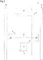
- FIG 1 shows a schematic of an example of the monitoring device 1 according to the invention.
- the monitoring device 1 is used to protect access to a danger area on a dangerous installation 2 .
- Access to the danger area is via a conveyor 3, the conveyor belt of which is moved in the direction of movement marked F in order to convey transport goods 5 arranged on pallets 4 into the danger area.
- transported goods 5 can be taken out of the danger area in the same way.
- the conveyor 3 is protected by fencing 11 attached to the side.
- the monitoring device 1 includes a safety sensor 6 in the form of an optical sensor.
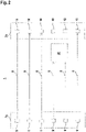
- the safety sensor 6 is designed as a light curtain ( figure 2 ).
- the light curtain has a series arrangement of transmitters 9 emitting light beams 8 in a first housing 7a and a series arrangement of receivers 10 in a second housing 7b.
- the light beams 8 define beam axes of the light curtain and span a flat protective field that is oriented in a vertical plane and thus runs perpendicular to the horizontal surface of the conveyor belt of the conveyor device 3 .
- the transmitters 9 are activated one after the other cyclically by means of a transmitter control, not shown.
- the receivers 10 are optically synchronized with the transmitters 9 in a known manner.
- Each transmitter 9 forms a beam axis of the light curtain with the assigned receiver 10 .
- the received signals generated in the receivers 10 are evaluated in an evaluation unit (not shown) to generate a binary switching signal 16 .
- the switching states of the switching signal 16 indicate whether an object 30 is in the protective field or not.
- the evaluation unit has a redundant, preferably two-channel structure.
- a safety function is triggered by the switching signal 16, in particular the hazardous system 2 is shut down.
- the safety sensor 6 can be bypassed as a function of muting signals from muting sensors if a permissible object 30 such as, for example, transported goods 5 stored on a pallet 4 passes the protective field of the safety sensor 6 . By bridging the safety sensor 6, this does not trigger a safety function when the permissible object 30 passes the protective field and the transported goods 5 can be fed to the system 2 without the latter being shut down.
- figure 3 shows an exemplary embodiment of the operation of the monitoring device 1 according to FIG figure 1 .
- the safety sensor 6 leads in an area of the protective field that figure 3 is characterized by the beam axes shown with solid lines, a protective field monitoring in such a way that it triggers a safety function for the system 2 when an object is detected in this area, in particular the system 2 is shut down.
- the safety sensor 6 can be switched to a muting mode by means of muting signals, with a protective field interruption detection being carried out in a region of the protective field.
- this area is formed by the entire protective field, ie the beam axes with solid lines and the beam axes with dashed lines.
- the protective field monitoring and protective field interruption detection are operated with different verification configurations.
- the safety sensor 6 is designed to carry out a protective field monitoring detection, in which it is checked whether the entire protective field is object-free.
- the detection configurations can be given by different resolutions of the light curtain.
- the light curtain is operated with reduced resolution, i.e. an object message is only generated if several related, adjacent beam axes are interrupted at the same time.
- the light curtain is operated with the highest possible resolution, i.e. each beam axis reports an object intervention individually.
- detection configurations can be spatially and/or temporally variable.
- Verification configurations can be specified depending on previous protective field interruptions.
- the muting signals are advantageously formed by an external control signal 301 and an interruption in the protective field detected by the safety sensor 6. A transition to muting mode only takes place if the protective field interruption is registered within a specified time interval after the control signal 301.
- 301 designates an external control signal which is used to initiate a muting operation.
- the time profile of the binary output signal of the safety sensor 6 for protective field monitoring or protective field interruption detection is shown at 302 .
- 201 phases of the monitoring operation of the safety sensor 6 are shown. Muting phases, ie phases in which the safety sensor 6 is in muting mode, are represented by 202, 202'.
- a muting announcement takes place. Since the muting is confirmed within a predetermined time interval after this announcement with the edge 402 of the output signal of the safety sensor 6, the muting phase 202 is initiated.
- the signal edge 403 signals that the protective field or the monitored area of the protective field is free.
- the signal edge 404 of the external control signal 301 ends the muting phase 202.
- the signal edges 401' and 402' initiate the second muting phase 202', which is ended again by the signal edges 405, 406.
- the monitoring device 1 uses the protective field monitoring detection to check whether the entire protective field has become object-free within a predetermined period of time.
- the predetermined period of time can be dependent on a muting phase 202 during which the safety sensor 6 is in muting mode.
- the specified period of time lies between two muting phases 202, 202' or between the time at which safety sensor 6 is switched on and the first muting phase 202.
- the specified period of time includes several muting phases 202.
- the predetermined period of time can be related in time to the external control signal 301 forming a muting signal.
- the system 2 is advantageously locked via the safety sensor 6 .
- the muting signals are blocked if the result of the protective field monitoring detection is negative.
- FIG figure 7 shows a first exemplary embodiment of a circuit logic for the monitoring device 1 according to FIG figure 1 .
- the components of the circuit logic are integrated in the safety sensor 6, ie in the light curtain.
- the circuit logic has a light curtain function 12, which is formed by the evaluation unit of the light curtain and which evaluates the received signals of the receiver 10 of the light curtain.
- a muting sequence logic 13 is also provided.
- Information signals 14 about the result of the protective field monitoring and information signals 15 about the result of the protective field monitoring detection are output to the muting sequence logic 13 by the light curtain function 12 .
- the switching signal 16 of the light curtain which can be used to trigger the safety function, is output in the muting sequence logic 13 .
- a control signal 18 corresponding to the external control signal 301 for initiating a muting phase 202 is input into the muting sequence logic 13 in an external controller 17 .
- the muting operation is controlled with this and with the results of the protective field monitoring.
- a further control signal 19 input from the external controller 17 into the muting sequence logic 13 can be used to specify detection configurations for the light curtain.
- FIG figure 8 shows a variant of the embodiment according to FIG figure 7 .
- This embodiment differs from the embodiment according to FIG figure 7 only because the muting sequence logic 13 now forms an external unit outside of the safety sensor 6 .
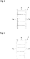
- the Figures 9 and 10 12 show exemplary embodiments of safety sensors 6 in the form of distance-measuring optical sensors, the distance measurements advantageously being carried out using a pulse propagation time method or a phase measuring method.
- These safety sensors 6 can be used instead of a light curtain for the monitoring device 1 according to FIG figure 1 be used.
- figure 9 shows an embodiment of an optical sensor in the form of a surface distance sensor, ie a scanning distance sensor.
- the optical sensor has a transmission light beam 20 emitting transmitting element 21 and receiving element 23 receiving received light beams 22 .
- the transmitting element 21 emits transmitted light beams 20 in the form of light pulses.
- the transmitted light beams 20 are reflected on an object 30 to be detected and guided as received light beams 22 to the receiving element 23, with the corresponding light propagation time of the light pulses to the object 30 and back to the optical sensor being evaluated for the distance determinations.
- the sensor components of the optical sensor are integrated in a housing 24, the transmitting element 21 and the receiving element 23 with an upstream receiving optics 25 being arranged in the housing 24 in a stationary manner.
- an object is detected in a flat detection area in that the transmitted light beams 20 are periodically deflected by means of a deflection unit 26 .
- the deflection unit 26 is motor-driven and includes a deflection mirror 27 which can be rotated about an axis of rotation D and on which the transmitted light beams 20 and received light beams 22 are deflected.
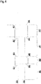
- figure 10 shows a variant of the area distance sensor according to FIG figure 9 .
- the periodic deflection of the transmitted light beams 20 and received light beams 22 takes place in that the transmitting element 21 and the receiving element 23 are arranged in a measuring head 28 that can be rotated about an axis of rotation D, with the measuring head 28 being rotatably mounted on a base 29.
Landscapes
- Engineering & Computer Science (AREA)
- General Engineering & Computer Science (AREA)
- Mechanical Engineering (AREA)
- Geophysics And Detection Of Objects (AREA)
Priority Applications (1)
| Application Number | Priority Date | Filing Date | Title |
|---|---|---|---|
| EP21158499.0A EP4047256A1 (fr) | 2021-02-22 | 2021-02-22 | Dispositif de surveillance et procédé de sécurisation d'une zone dangereuse au moyen d'un dispositif de surveillance |
Applications Claiming Priority (1)
| Application Number | Priority Date | Filing Date | Title |
|---|---|---|---|
| EP21158499.0A EP4047256A1 (fr) | 2021-02-22 | 2021-02-22 | Dispositif de surveillance et procédé de sécurisation d'une zone dangereuse au moyen d'un dispositif de surveillance |
Publications (1)
| Publication Number | Publication Date |
|---|---|
| EP4047256A1 true EP4047256A1 (fr) | 2022-08-24 |
Family
ID=74673135
Family Applications (1)
| Application Number | Title | Priority Date | Filing Date |
|---|---|---|---|
| EP21158499.0A Pending EP4047256A1 (fr) | 2021-02-22 | 2021-02-22 | Dispositif de surveillance et procédé de sécurisation d'une zone dangereuse au moyen d'un dispositif de surveillance |
Country Status (1)
| Country | Link |
|---|---|
| EP (1) | EP4047256A1 (fr) |
Citations (5)
| Publication number | Priority date | Publication date | Assignee | Title |
|---|---|---|---|---|
| EP1826589A1 (fr) * | 2006-02-25 | 2007-08-29 | Leuze lumiflex GmbH + Co. KG | Capteur optique destiné à la surveillance d'une zone de sécurité |
| EP1923726A2 (fr) * | 2006-11-14 | 2008-05-21 | Leuze lumiflex GmbH + Co. KG | Capteur optique |
| DE202007014653U1 (de) * | 2007-10-19 | 2009-03-05 | Sick Ag | Konfigurationsmittel für Sicherheits-Lichtgitter |
| EP3133423A1 (fr) * | 2015-08-17 | 2017-02-22 | Rockwell Automation Safety AG | Système et procédé de réglage dynamique de l'inhibition d'un rideau de lumière |
| EP3633413A1 (fr) * | 2018-10-02 | 2020-04-08 | Leuze electronic GmbH + Co. KG | Dispositif de sécurité |
-
2021
- 2021-02-22 EP EP21158499.0A patent/EP4047256A1/fr active Pending
Patent Citations (5)
| Publication number | Priority date | Publication date | Assignee | Title |
|---|---|---|---|---|
| EP1826589A1 (fr) * | 2006-02-25 | 2007-08-29 | Leuze lumiflex GmbH + Co. KG | Capteur optique destiné à la surveillance d'une zone de sécurité |
| EP1923726A2 (fr) * | 2006-11-14 | 2008-05-21 | Leuze lumiflex GmbH + Co. KG | Capteur optique |
| DE202007014653U1 (de) * | 2007-10-19 | 2009-03-05 | Sick Ag | Konfigurationsmittel für Sicherheits-Lichtgitter |
| EP3133423A1 (fr) * | 2015-08-17 | 2017-02-22 | Rockwell Automation Safety AG | Système et procédé de réglage dynamique de l'inhibition d'un rideau de lumière |
| EP3633413A1 (fr) * | 2018-10-02 | 2020-04-08 | Leuze electronic GmbH + Co. KG | Dispositif de sécurité |
Similar Documents
| Publication | Publication Date | Title |
|---|---|---|
| EP1544535B1 (fr) | Dispositif de surveillance de la zone dans la portée d'un outil de travail | |
| EP2180348B1 (fr) | Barrière lumineuse de sécurité et procédé correspondant de surveillance d'une zone de protection | |
| EP2306063B2 (fr) | Capteur de sécurité | |
| DE102008004941B4 (de) | Sicherheitsanordnung und Verfahren | |
| EP3910230A1 (fr) | Dispositif de surveillance | |
| EP3885635B1 (fr) | Dispositif de surveillance permettant de sécuriser l'accès à une zone dangereuse à l'aide d'un capteur de sécurité | |
| EP3415804B1 (fr) | Dispositif de sécurité | |
| EP1826589B1 (fr) | Capteur optique destiné à la surveillance d'une zone de sécurité | |
| EP3633413B1 (fr) | Dispositif de sécurité | |
| EP1837586B1 (fr) | Dispositif de surveillance d'une zone dangereuse près d'une machine | |
| EP3399223B1 (fr) | Dispositif de protection d'une installation | |
| EP4047256A1 (fr) | Dispositif de surveillance et procédé de sécurisation d'une zone dangereuse au moyen d'un dispositif de surveillance | |
| EP3910227B1 (fr) | Dispositif de surveillance et procédé de fonctionnement d'un dispositif de surveillance | |
| EP3945237A1 (fr) | Dispositif de surveillance et procédé de fonctionnement d'un dispositif de surveillance | |
| EP3910228B1 (fr) | Dispositif de surveillance et procédé de fonctionnement un dispositif de surveillance | |
| DE102006029643A1 (de) | Vorrichtung zur Überwachung eines Gefahrenbereichs | |
| EP3910229A1 (fr) | Dispositif de surveillance | |
| EP3974699A1 (fr) | Dispositif de surveillance | |
| EP4137735B1 (fr) | Dispositif de surveillance et procédé de fonctionnement d'un systeme capteur | |
| EP3875993B1 (fr) | Dispositif capteur et procédé de fonctionnement d'un dispositif capteur | |
| EP3862617B1 (fr) | Dispositif de sécurisation d'une zone dangereuse | |
| EP4365477A1 (fr) | Dispositif de surveillance | |
| EP4151899A1 (fr) | Dispositif de surveillance | |
| DE202022103201U1 (de) | Überwachungseinrichtung | |
| EP4354010A1 (fr) | Dispositif de surveillance |
Legal Events
| Date | Code | Title | Description |
|---|---|---|---|
| PUAI | Public reference made under article 153(3) epc to a published international application that has entered the european phase |
Free format text: ORIGINAL CODE: 0009012 |
|
| STAA | Information on the status of an ep patent application or granted ep patent |
Free format text: STATUS: REQUEST FOR EXAMINATION WAS MADE |
|
| 17P | Request for examination filed |
Effective date: 20210809 |
|
| AK | Designated contracting states |
Kind code of ref document: A1 Designated state(s): AL AT BE BG CH CY CZ DE DK EE ES FI FR GB GR HR HU IE IS IT LI LT LU LV MC MK MT NL NO PL PT RO RS SE SI SK SM TR |