EP3974699A1 - Dispositif de surveillance - Google Patents
Dispositif de surveillance Download PDFInfo
- Publication number
- EP3974699A1 EP3974699A1 EP20197956.4A EP20197956A EP3974699A1 EP 3974699 A1 EP3974699 A1 EP 3974699A1 EP 20197956 A EP20197956 A EP 20197956A EP 3974699 A1 EP3974699 A1 EP 3974699A1
- Authority
- EP
- European Patent Office
- Prior art keywords
- light curtain
- monitoring device
- protective field
- function
- permissible
- Prior art date
- Legal status (The legal status is an assumption and is not a legal conclusion. Google has not performed a legal analysis and makes no representation as to the accuracy of the status listed.)
- Pending
Links
Images


Classifications
-
- F—MECHANICAL ENGINEERING; LIGHTING; HEATING; WEAPONS; BLASTING
- F16—ENGINEERING ELEMENTS AND UNITS; GENERAL MEASURES FOR PRODUCING AND MAINTAINING EFFECTIVE FUNCTIONING OF MACHINES OR INSTALLATIONS; THERMAL INSULATION IN GENERAL
- F16P—SAFETY DEVICES IN GENERAL; SAFETY DEVICES FOR PRESSES
- F16P3/00—Safety devices acting in conjunction with the control or operation of a machine; Control arrangements requiring the simultaneous use of two or more parts of the body
- F16P3/12—Safety devices acting in conjunction with the control or operation of a machine; Control arrangements requiring the simultaneous use of two or more parts of the body with means, e.g. feelers, which in case of the presence of a body part of a person in or near the danger zone influence the control or operation of the machine
- F16P3/14—Safety devices acting in conjunction with the control or operation of a machine; Control arrangements requiring the simultaneous use of two or more parts of the body with means, e.g. feelers, which in case of the presence of a body part of a person in or near the danger zone influence the control or operation of the machine the means being photocells or other devices sensitive without mechanical contact
- F16P3/144—Safety devices acting in conjunction with the control or operation of a machine; Control arrangements requiring the simultaneous use of two or more parts of the body with means, e.g. feelers, which in case of the presence of a body part of a person in or near the danger zone influence the control or operation of the machine the means being photocells or other devices sensitive without mechanical contact using light grids
-
- G—PHYSICS
- G01—MEASURING; TESTING
- G01V—GEOPHYSICS; GRAVITATIONAL MEASUREMENTS; DETECTING MASSES OR OBJECTS; TAGS
- G01V8/00—Prospecting or detecting by optical means
- G01V8/10—Detecting, e.g. by using light barriers
- G01V8/20—Detecting, e.g. by using light barriers using multiple transmitters or receivers
Definitions
- the invention relates to a monitoring device according to the preamble of claim 1.
- Monitoring devices of this type are used in the field of safety technology, with the safety sensor generally being used to monitor the danger area of a hazardous installation, with the term installation also generally including machines, robots and the like.
- the monitoring device is used to secure access to a hazardous area of a plant, with access to the hazardous area being provided via a conveying device.
- the monitoring device typically has a light curtain as a safety sensor, with which a protective field lying in one plane is monitored.
- the light curtain generates a switching signal whose switching states indicate whether an object is present in the protective field or not. If an object is detected in the protective field with the light curtain, a safety function is triggered by the corresponding switching signal. For example, the switch signal from a control unit activates the system, which shuts it down so that the system can no longer pose a risk.
- Permitted objects such as transport goods stored on pallets, which are required for carrying out work processes in the system, are generally also fed to the system on the conveyor device. Since such permitted objects are not safety-critical, the safety function would be triggered at the movement of permissible objects through the protective field of the light curtain lead to an unnecessary standstill of the machine.
- muting sensors are arranged upstream of the safety sensor in known monitoring devices in conveying directions. If an object is detected as a permissible object with the muting sensors, the safety sensor is bypassed for a specified period of time so that it no longer triggers the safety function when the permissible object passes the protective field.
- Such muting sensors are typically formed by light barrier/light scanner arrangements. Permitted objects often cannot be reliably detected with such arrangements.
- Another disadvantage is that the coordination of the timing and the evaluation of the signals of the muting sensors is imprecise, since the time at which the object was detected by the muting sensors must be extrapolated based on the conveyor speed to determine the period of time until the permissible object has actually passed the safety sensor.
- the actual conveying speed cannot always be precisely set or exactly known.
- the DE 10 2007 033 766 B4 relates to a method for detecting objects in a monitored area using a light grid comprising a number of beam axes, each of which is formed by a transmitter emitting transmitted light beams and an associated receiver, the beam axes being uninterrupted when the monitored area is clear and at least one when an object is invaded in the monitored area Beam axis is interrupted.
- An object report is generated in an evaluation unit when a safety-critical object enters the surveillance area, with a non-safety-critical object in the evaluation unit, which has a surface with a rectangular outer contour in the projection perpendicular to the plane of the beam axes, passing through the surveillance area it can be identified that during an entry phase, in which the front edge of the object enters the surveillance area, and a transit phase, in which the height of the object is detected.
- the beam axes interrupted by the non-safety-critical object are registered as different muting phases, and these are used to check whether specific object features of the non-safety-critical object stored in the evaluation unit are fulfilled for the running-in phase and through-flow phase.
- a muting signal is generated in the evaluation unit.
- the muting can be canceled in a time-resolved manner by switching off the muting signal in the individual muting phases.
- the object of the invention is to provide a monitoring device of the type mentioned at the outset which, with a structurally simple design, has a high level of functionality and at the same time a high level of functional reliability.
- the invention relates to a monitoring device with a light curtain, which has an arrangement of transmitters emitting light beams and an arrangement of receivers receiving light rays, the light curtain being designed for object detection within a protective field and having an evaluation unit in which a safety function is performed when an object is registered in the protective field can be triggered and with means for generating a muting function, by means of which the safety function can be bridged.
- the muting function is generated depending on signals from the light curtain.
- a muting function is only generated if the light curtain detects an object structure that extends to the lower edge of the protective field.
- the invention further relates to a corresponding method.
- the monitoring device according to the invention is generally used for monitoring a danger zone in a hazardous installation.
- the monitoring device is used particularly advantageously to secure access to a danger area, with access to the danger area taking place in particular via a transport device.
- the monitoring device advantageously forms a safety system that meets the safety requirements for use in safety-relevant applications, in particular in the area of personal protection.
- the components of the safety system have a fail-safe design. This is achieved in particular by a redundant, multi-channel design of the sensor's evaluation unit, so that the sensor forms a safety sensor.
- the monitoring device advantageously includes a controller which is used in particular to control the system monitored by the sensor.
- the controller is then designed as a safety controller and also has a redundant, multi-channel structure.
- the light curtain designed in particular as a safety sensor, is provided as the central safety component of the monitoring device, with which a protective field that advantageously runs in one plane is monitored.
- the safety sensor generates a binary switching signal whose switching states indicate whether an object is in the protective field or not. If the safety sensor registers an object intrusion in the protective field, the switching signal triggers a safety function, for example shutting down the system so that it can no longer pose a risk.
- a bridging function i.e. a muting function
- a muting function is provided to prevent the system from stopping unnecessarily when permissible objects, such as goods to be transported to the system, are to be conveyed through the protective field into the danger zone of the system.
- the muting function is activated, the safety sensor is completely or partially bypassed, i.e. muted, so that the transported goods can pass through the protective field without the safety sensor triggering the safety function.
- An essential advantage of the monitoring device according to the invention is that a muting function can be generated using signals from the light curtain itself, ie the safety function of the light curtain for monitoring the danger area is bypassed, ie muted. No external muting sensors are required to generate the muting function, which considerably reduces the design and circuitry of the monitoring device.
- the muting function is limited in that it can essentially only be generated when a permissible object with a specific geometry is detected.
- the functionality of the muting function is considerably expanded. This is achieved in a surprisingly simple manner in that the muting function is then generated when with an object structure extending to the lower edge of the protective field is detected by the light curtains.
- This object structure must extend over a specific, extensive area, i.e. it must not only be a local, one-time object intervention in the protective field.
- the invention is based on the finding that non-dangerous, permissible objects such as transport goods are flat objects that rest on a base. By detecting objects in the lower edge area of the protective field as a criterion for recognizing permissible objects, these can be reliably differentiated from safety-critical objects, in particular people.
- the light curtain can also be used to reliably detect a number of permissible objects that are superimposed, that is to say that are stacked or arranged one behind the other or next to one another, and can be distinguished from safety-critical objects.
- a muting function is generated when structural features of permissible objects are detected with the light curtain.
- front and/or rear structures of permissible objects are particularly advantageously detected as a criterion for generating the muting function.
- the muting function is generated in such a way that a permissible object passes the light curtain without it generating a safety function.
- a transport device is provided with a conveyor surface on which permissible objects are transported.
- the light curtain is arranged on the transport device in such a way that the lower edge connects the protective field of the light curtain to the conveying surface and protrudes at an angle of inclination towards or over it.
- the permissible objects are advantageously transported on a horizontal conveying surface, which is bordered by the lower area of the protective field of the light curtain, the protective field advantageously but not necessarily being oriented perpendicularly to the conveying surface.
- each transmitter of the light curtains is assigned a receiver, with this transmitter and receiver forming a beam axis of the light curtain, with the light beams of the transmitters of all beam axes impinging unhindered on the respectively assigned receiver when the protective field is free, and with at least a beam axis is interrupted.
- the transmitter and receiver of the light curtain are arranged on opposite edges of the protective field.
- the light curtain then works according to the principle of a one-way light barrier. In this case, if the protective field is free, the light beams of the individual beam axes are guided directly to the respective transmitter and the assigned receiver.
- the emitters and receivers of the light curtain are arranged on the same edge of the protective field and the opposite edge of the protective field is delimited by a reflector.
- the light curtain then forms a reflection light curtain.
- the protective field is clear, the light beams of the individual beam axes are guided from the respective transmitter to the reflector and reflected from there to the assigned receiver.
- the monitoring device has means for recording the time and/or distance and/or recording of the transport device of objects transported on the transport device.
- At least one sensor element is advantageously provided as a means for detecting the path and/or the transport direction, by means of which the marking elements on the transport device can be detected.
- Path signals can also be specified by an external controller, in particular in the form of pulsed signals.
- a muting function can be generated with the light curtain depending on a time window and/or distance window and/or direction of transport monitored object detection.
- permissible objects can be permitted, which can be recognized with object detection that is monitored by time or distance window.
- objects that have openings such as gaps or holes can also be permissible objects.
- openings lead to a short-term release of individual beam axes, which is or away-window-controlled object detection can be evaluated as permissible for the detection of a permissible object.
- a muting function is only generated if a rear closed structure and/or a front closed structure of an object is detected within a predetermined time window or path window by registering interrupted beam axes.
- the rear and front structures of objects can be precisely analyzed by the displacement or time-resolved detection, and thus permissible objects can be reliably recognized and differentiated from objects that are not permissible.
- the type of object structures to be recorded can also be flexibly specified by the size of the path or time window.
- vertical object structures i.e. object structures running along the plane of the protective field, can be selectively detected with small distance or time windows. This is advantageous if side surfaces of cuboid objects are to be recognized.
- the size of the path or time window is expediently adapted to the conveying speed of the transport device.
- permissible objects are taught or specified.
- a learning process can be carried out, for example, by an enable signal from an external controller, in particular the controller of the system to be monitored or the transport device. Teaching can also take place after the transport device has been switched on, so that permissible objects are then taught in during a first passage through the light curtain.
- minimum and/or maximum sizes of permissible objects are taught or specified.
- This specification is expediently dependent on the transport speed of the transport device and the spread of the sizes of the permissible objects.
- edges of permissible objects are recognized within predetermined tolerance ranges or blurred areas determined by marginal rays.
- the height of the permissible objects can fluctuate when they pass through the light curtain.
- tolerance ranges can be specified within which edge contours of permissible objects must be detected in order to identify them as such.
- the tolerance ranges then give proposes a range of interrupted beam axes corresponding to the detection of an edge contour of the allowed object.
- blurred areas defined by edge rays can also be specified for the detection of edge contours of permissible objects.
- the received signals of the receivers are usually evaluated with only one threshold value in order to determine whether the respective beam axis is interrupted or not. By providing a plurality of threshold values, it is also possible to assess whether individual beam axes are only partially interrupted, ie in this case part of the light beams is interrupted by an object.
- the light curtain can be operated with a reduced resolution.
- figure 1 1 shows an example of a light curtain 1 for a monitoring device 100, as in FIGS Figures 3 and 13 is shown.
- the light curtain 1 has a series arrangement of transmitters 3 emitting light beams 2 in a first housing 12a and a series arrangement of receivers 4 in a second housing 12b.
- the light beams 2 span a two-dimensional surveillance area that is oriented in a vertical plane.
- the transmitters 3 are activated one after the other cyclically by means of a transmitter control, not shown.
- the receivers 4 are optically synchronized with the transmitters 3 in a known manner.
- the received signals generated in the receivers 4 are evaluated in an evaluation unit (not shown) to generate a binary switching signal.
- the switching states of the switching signal indicate whether an object 5 is in the monitored area or not.
- the evaluation unit has a redundant, preferably two-channel structure.
- the light curtain 1 according to figure 1 can also be designed as a reflection light curtain.
- the transmitters 3 and receivers 4 are paired in a housing 12a at an edge of the surveillance area arranged, while a reflector is arranged at the opposite edge of the surveillance area.
- the monitoring area is free, the light beams 2 from the transmitter 3 are guided to the reflector and reflected from there to the associated receiver 4 .
- figure 2 shows an example of a variant of a light curtain 1 with deflection mirrors 38.
- the light curtain 1 has a series arrangement of transmitters 3 emitting light beams 2 in a first housing 12 and a receiver 4 in the same housing 12 .
- a series arrangement of receivers 4 can also be provided.
- 'deflecting mirrors 38 are attached, which deflect the light beams 2 of the transmitter 3 to light beams 2b for the receiver 4.
- the light beams 2, 2b span a flat monitoring area which is oriented in a vertical plane and thus runs perpendicular to the horizontal surface of the conveyor belt of the conveyor device.
- the transmitters 3 are activated one after the other cyclically by means of a transmitter control, not shown.
- the receiver 4 is electrically or optically synchronized with the transmitter 3 in a known manner.
- the received signals generated in the receivers 4 are evaluated in an evaluation unit (not shown) to generate a binary switching signal.
- the switching states of the switching signal indicate whether an object 5 is in the monitored area or not.
- the evaluation unit has a redundant, preferably two-channel structure.
- FIG 3 shows an exemplary embodiment of the monitoring device 100 according to the invention.
- the monitoring device 100 is used to secure a danger area 13 of a system 14. Access to the danger area 13 takes place solely via a movable unit in the form of a transport device 15, which in the present case is in the form of a conveyor belt.
- the transport device 15 is driven by a drive, not shown.
- the system 14 and the transport device 15 are controlled by a safety controller 16 .
- Access to the danger zone 13 is monitored using a light curtain 1 .
- a protective field 17 is monitored.
- a binary switching signal is generated with a switching state that triggers a safety function.
- the switching signal is output to the safety controller 16 .
- the safety function is formed by the system 14 being shut down.
- Permissible objects in the form of transport goods 18 are transported in a transport direction I on the transport device 15 . These permissible objects are not dangerous and should be guided through the protective field 17 of the light curtains to the system 14 without triggering the safety function.
- a bridging function that is to say a muting function, is provided, by means of which the sensor 1 is bypassed so that it does not trigger a safety function when a transport item 18 passes the protective field 17 .
- the entire protective field 17 can be bypassed or, in the case of partial muting, only the part 17' of the protective field 17 within which the Cargo 18 is available. If the contours of the transported goods vary, the bridged part 17' of the protective field 17 also varies.
- the muting function is controlled or monitored as a function of a path detection carried out using sensors.
- the sensor elements 19, 20 are in the form of optical, magnetic, inductive or capacitive sensor means.
- the sensor elements 19, 20 preferably generate pulse-shaped sensor signals.
- the speed or distances of the transport device 15 can thus be determined on the basis of sensor signals from the sensor elements 19 , 20 .
- the sensor elements 19, 20 can be designed as radar sensors, optical sensors or ultrasonic sensors 19c.
- Speed signals and direction signals can thus be determined by evaluating the Doppler effect, i.e. the change in frequency of the reflected waves compared to the transmitted wave.
- Path information can be determined from the speed signal determined in this way by summing up the speed signal.
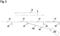
- FIG 4 shows a section of the transport device 15 with several transport belt elements 21, which are moved by means of the drive in the directions indicated by the arrows I, II. Edges 22 protruding from the undersides of the conveyor belt elements 21 form marking elements which are detected with the first sensor means.
- these first sensor elements 19 , 20 have two sensor elements 19 , 20 arranged one behind the other in the conveying direction of the transport device 15 .
- figure 5 shows a sensor arrangement with an ultrasonic sensor 19c with a transmitted ultrasonic wave 191 with a first specific frequency and a received ultrasonic wave 192 with a frequency changed by the speed of the transport device 15. Both the direction and the speed of the transport device 15 can be determined from the change in frequency of the received signal. Path information can be obtained by summing up the speed values.
- a radar sensor can also be provided instead of an ultrasonic sensor 19c.
- Path information is obtained by counting the pulsed sensor signals, and the speed of the transport device 15 is determined by the time intervals between the sensor signals.
- the transport direction of the transport device 15 is determined by evaluating the sequence of the sensor signals of the sensor elements 19, 20.
- Errors e.g. short circuit or oscillation
- the sensor elements 19, 20 can be detected by monitoring time intervals or time relationships and/or the time expectations of pulse widths, e.g. in relation to the period or time intervals, e.g. in relation to the period.
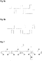
- figure 7 shows a modification of the embodiment according to FIG figure 5 .
- sensor element 19 In contrast to the embodiment according to figure 5 only sensor element 19 is provided, so that no direction detection is possible in this case.
- the evaluation of the time profile of the sensor signals 19 ( figure 8 ) is otherwise analogous to the embodiment according to Figures 6a, 6b .
- figure 9 shows a modification of the embodiment according to FIG figure 7 such that the conveyor belt elements 21 have different marking elements in the form of edges 22, 22'.
- the sensor 19 again has only one sensor element 19, direction detection is again possible on the basis of the different sensor signals generated by the different edges 22, 22'.
- Figure 10a shows the sensor signals of sensor element 19 for transport direction I.
- Figure 10b shows the sensor signals of sensor element 19 for transport direction II.
- the sensor signals are evaluated analogously to the embodiment of FIGS. 6a, 6b.
- figure 11 shows a variant of the transport device 15 with a drive in the form of a toothed belt drive 23 with a toothed belt 24.
- Marking elements in the form of elevations 25 or depressions 26 or material structure elements 28 can be provided on the toothed belt 24, which are scanned with the sensor 19.
- marking elements can also be provided on the drive axle 27 of the toothed belt drive 13 .
- Figures 12a - 12g show different embodiments of such marking elements
- the Figures 12a - 12d show a plan view of the front wheel portion of the drive axle 27, whereas the Figures 12e - 12g show longitudinal sections.
- Figures 12a, 12b show marking elements forming geometry structure elements in the form of elevations 25, while the figures show marking elements in the form of depressions 26.
- Figure 12g shows marking elements in the form of material structure elements 28. These form local areas with different material properties than the surrounding area, with these material structure elements 28 being able to be detected with the first sensor means.
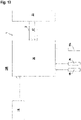
- figure 13 shows a further embodiment of the monitoring device 100 according to the invention in the form of a block diagram.
- figure 13 shows the safety sensor in the form of the light curtain 1 with a transmitter unit 30 having the transmitter 3 and a receiver unit 31 having the receiver 4.
- a controller is integrated in the receiver unit 31, which forms the evaluation unit and takes over the muting control.
- the controller 16 of the system 14 is connected to the receiver unit 31 and supplies path signals to the receiver unit 31.
- sensor signals generated by sensors 19, 19c, 20 are read into the receiver unit 31 in order to generate path signals and speed signals.
- the light curtain 1 again generates light beams 2b, which form the protective field 17 oriented in a vertical plane.
- figure 14 shows a first application example of the monitoring device 100 according to the invention.
- figure 14 shows the light curtain 1 on the transport device 15, the lower edge of the protective field 17 of the light curtain 1 adjoining the upper side of the transport device 15 forming a conveying surface.
- the protective field 17 is oriented in the vertical direction and thus perpendicular to the horizontal conveying surface.
- the beam axes formed by the light beams 2b of the light curtain 1 are denoted by 200-209.
- the beam axes 200 - 209 form the protective field 17.
- Packages 40 - 43 are transported in the direction of the light curtain 1 on the transport device 15 , as indicated by the arrow.
- the light curtain 1 is bridged for a period of time, ie muted, so that the packets 40 - 43 can pass through the light curtain 1 .
- the main criterion for identifying a permissible object is that it penetrates the lower edge of the protective field, in particular during a specific time window or travel window, ie interrupts the lowest beam axis 209 in the present case.
- the signals of the light curtain 1 are evaluated, controlled by a path window, in order to detect a permissible object.
- Path signals s1, s2 are used for path control, which are generated, for example, with sensors 19, 20 or safety controller 16 (FIG. 15).
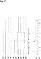
- figure 16 shows one according to the arrangement figure 14 largely corresponding arrangement. Unlike in the case of figure 14 now penetrates a package 42 in the protective field 17.
- the corresponding time diagrams for the structures 200 - 209 and the path signals s1, s2 of the sensors 19, 20 and the safety controller 16 shows figure 17 .
- the front contour of the package 40-43 entering the protective field 17 is detected within the travel window ⁇ s1.
- the beam axes 204, 205, 206, 207, 208 and in particular the bottom beam axis 209 are interrupted one after the other within the path window ⁇ s1.
- Package 42 is therefore considered a permissible object if the interruptions at the front edge are within a travel window ⁇ s1 and the absence of the interruptions at the rear edge are within a travel window ⁇ s2, so that light curtain 1 does not trigger the safety function.
- a corresponding monitoring of the rear contour of the package 42 takes place within the second travel window ⁇ s2.
- the transit time of an object 5 through the protective field 17 is monitored.
- the following requirements must be met cumulatively: within the entire travel window ⁇ s1, ⁇ s2 the bottom beam axis 209 of the light curtain 1 are interrupted.
- the entire passage ⁇ s can also be used as a criterion for a permissible object.
Landscapes
- Engineering & Computer Science (AREA)
- General Engineering & Computer Science (AREA)
- Physics & Mathematics (AREA)
- Life Sciences & Earth Sciences (AREA)
- General Life Sciences & Earth Sciences (AREA)
- General Physics & Mathematics (AREA)
- Geophysics (AREA)
- Mechanical Engineering (AREA)
- Geophysics And Detection Of Objects (AREA)
Priority Applications (1)
| Application Number | Priority Date | Filing Date | Title |
|---|---|---|---|
| EP20197956.4A EP3974699A1 (fr) | 2020-09-24 | 2020-09-24 | Dispositif de surveillance |
Applications Claiming Priority (1)
| Application Number | Priority Date | Filing Date | Title |
|---|---|---|---|
| EP20197956.4A EP3974699A1 (fr) | 2020-09-24 | 2020-09-24 | Dispositif de surveillance |
Publications (1)
| Publication Number | Publication Date |
|---|---|
| EP3974699A1 true EP3974699A1 (fr) | 2022-03-30 |
Family
ID=72644101
Family Applications (1)
| Application Number | Title | Priority Date | Filing Date |
|---|---|---|---|
| EP20197956.4A Pending EP3974699A1 (fr) | 2020-09-24 | 2020-09-24 | Dispositif de surveillance |
Country Status (1)
| Country | Link |
|---|---|
| EP (1) | EP3974699A1 (fr) |
Citations (4)
| Publication number | Priority date | Publication date | Assignee | Title |
|---|---|---|---|---|
| EP1331433A2 (fr) * | 2002-01-25 | 2003-07-30 | Keyence Corporation | Dispositif de sécurité photoélectrique à chemin optique multiple |
| EP1344973A2 (fr) * | 2002-03-12 | 2003-09-17 | REER S.p.A. | Colonne pour barrière lumineuse munie de capteurs désactivables |
| DE102007033766B4 (de) | 2007-07-18 | 2009-11-26 | Leuze Lumiflex Gmbh + Co. Kg | Lichtgitter |
| EP2474960A1 (fr) * | 2009-08-31 | 2012-07-11 | Omron Corporation | Capteur photoélectrique à plusieurs axes optiques et système de gestion de sécurité utilisant ledit capteur |
-
2020
- 2020-09-24 EP EP20197956.4A patent/EP3974699A1/fr active Pending
Patent Citations (4)
| Publication number | Priority date | Publication date | Assignee | Title |
|---|---|---|---|---|
| EP1331433A2 (fr) * | 2002-01-25 | 2003-07-30 | Keyence Corporation | Dispositif de sécurité photoélectrique à chemin optique multiple |
| EP1344973A2 (fr) * | 2002-03-12 | 2003-09-17 | REER S.p.A. | Colonne pour barrière lumineuse munie de capteurs désactivables |
| DE102007033766B4 (de) | 2007-07-18 | 2009-11-26 | Leuze Lumiflex Gmbh + Co. Kg | Lichtgitter |
| EP2474960A1 (fr) * | 2009-08-31 | 2012-07-11 | Omron Corporation | Capteur photoélectrique à plusieurs axes optiques et système de gestion de sécurité utilisant ledit capteur |
Similar Documents
| Publication | Publication Date | Title |
|---|---|---|
| EP1548351B1 (fr) | Dispositif de surveillance d'une zone de couverture près d'une machine | |
| EP1544535B1 (fr) | Dispositif de surveillance de la zone dans la portée d'un outil de travail | |
| EP2180348B1 (fr) | Barrière lumineuse de sécurité et procédé correspondant de surveillance d'une zone de protection | |
| EP1046925B1 (fr) | Dispositif optoélectronique | |
| EP1089030A2 (fr) | Procédé et dispositif de contrôle d'une zone de protection | |
| DE4422497A1 (de) | Optoelektronische Vorrichtung zum Erfassen von Gegenständen in einem Überwachungsbereich | |
| EP3910230A1 (fr) | Dispositif de surveillance | |
| EP2306063B2 (fr) | Capteur de sécurité | |
| DE10312972B3 (de) | Optischer Sensor | |
| EP3885635B1 (fr) | Dispositif de surveillance permettant de sécuriser l'accès à une zone dangereuse à l'aide d'un capteur de sécurité | |
| DE19828000C2 (de) | Verfahren zur optoelektronischen Überwachung eines Schutzbereichs | |
| EP3415804B1 (fr) | Dispositif de sécurité | |
| EP1826589B1 (fr) | Capteur optique destiné à la surveillance d'une zone de sécurité | |
| EP3633413B1 (fr) | Dispositif de sécurité | |
| EP3974699A1 (fr) | Dispositif de surveillance | |
| EP3945237A1 (fr) | Dispositif de surveillance et procédé de fonctionnement d'un dispositif de surveillance | |
| EP3919801A1 (fr) | Dispositif de surveillance | |
| EP3910227B1 (fr) | Dispositif de surveillance et procédé de fonctionnement d'un dispositif de surveillance | |
| DE102017119283B4 (de) | Sensorsystem | |
| EP3910228B1 (fr) | Dispositif de surveillance et procédé de fonctionnement un dispositif de surveillance | |
| EP3910229A1 (fr) | Dispositif de surveillance | |
| EP4047256A1 (fr) | Dispositif de surveillance et procédé de sécurisation d'une zone dangereuse au moyen d'un dispositif de surveillance | |
| EP3945238B1 (fr) | Dispositif de surveillance et procédé de fonctionnement d'un dispositif de surveillance | |
| EP4365477A1 (fr) | Dispositif de surveillance | |
| EP3875993B1 (fr) | Dispositif capteur et procédé de fonctionnement d'un dispositif capteur |
Legal Events
| Date | Code | Title | Description |
|---|---|---|---|
| PUAI | Public reference made under article 153(3) epc to a published international application that has entered the european phase |
Free format text: ORIGINAL CODE: 0009012 |
|
| STAA | Information on the status of an ep patent application or granted ep patent |
Free format text: STATUS: REQUEST FOR EXAMINATION WAS MADE |
|
| 17P | Request for examination filed |
Effective date: 20210511 |
|
| AK | Designated contracting states |
Kind code of ref document: A1 Designated state(s): AL AT BE BG CH CY CZ DE DK EE ES FI FR GB GR HR HU IE IS IT LI LT LU LV MC MK MT NL NO PL PT RO RS SE SI SK SM TR |