EP3974699A1 - Monitoring device - Google Patents
Monitoring device Download PDFInfo
- Publication number
- EP3974699A1 EP3974699A1 EP20197956.4A EP20197956A EP3974699A1 EP 3974699 A1 EP3974699 A1 EP 3974699A1 EP 20197956 A EP20197956 A EP 20197956A EP 3974699 A1 EP3974699 A1 EP 3974699A1
- Authority
- EP
- European Patent Office
- Prior art keywords
- light curtain
- monitoring device
- protective field
- function
- permissible
- Prior art date
- Legal status (The legal status is an assumption and is not a legal conclusion. Google has not performed a legal analysis and makes no representation as to the accuracy of the status listed.)
- Pending
Links
Images


Classifications
-
- F—MECHANICAL ENGINEERING; LIGHTING; HEATING; WEAPONS; BLASTING
- F16—ENGINEERING ELEMENTS AND UNITS; GENERAL MEASURES FOR PRODUCING AND MAINTAINING EFFECTIVE FUNCTIONING OF MACHINES OR INSTALLATIONS; THERMAL INSULATION IN GENERAL
- F16P—SAFETY DEVICES IN GENERAL; SAFETY DEVICES FOR PRESSES
- F16P3/00—Safety devices acting in conjunction with the control or operation of a machine; Control arrangements requiring the simultaneous use of two or more parts of the body
- F16P3/12—Safety devices acting in conjunction with the control or operation of a machine; Control arrangements requiring the simultaneous use of two or more parts of the body with means, e.g. feelers, which in case of the presence of a body part of a person in or near the danger zone influence the control or operation of the machine
- F16P3/14—Safety devices acting in conjunction with the control or operation of a machine; Control arrangements requiring the simultaneous use of two or more parts of the body with means, e.g. feelers, which in case of the presence of a body part of a person in or near the danger zone influence the control or operation of the machine the means being photocells or other devices sensitive without mechanical contact
- F16P3/144—Safety devices acting in conjunction with the control or operation of a machine; Control arrangements requiring the simultaneous use of two or more parts of the body with means, e.g. feelers, which in case of the presence of a body part of a person in or near the danger zone influence the control or operation of the machine the means being photocells or other devices sensitive without mechanical contact using light grids
-
- G—PHYSICS
- G01—MEASURING; TESTING
- G01V—GEOPHYSICS; GRAVITATIONAL MEASUREMENTS; DETECTING MASSES OR OBJECTS; TAGS
- G01V8/00—Prospecting or detecting by optical means
- G01V8/10—Detecting, e.g. by using light barriers
- G01V8/20—Detecting, e.g. by using light barriers using multiple transmitters or receivers
Definitions
- the invention relates to a monitoring device according to the preamble of claim 1.
- Monitoring devices of this type are used in the field of safety technology, with the safety sensor generally being used to monitor the danger area of a hazardous installation, with the term installation also generally including machines, robots and the like.
- the monitoring device is used to secure access to a hazardous area of a plant, with access to the hazardous area being provided via a conveying device.
- the monitoring device typically has a light curtain as a safety sensor, with which a protective field lying in one plane is monitored.
- the light curtain generates a switching signal whose switching states indicate whether an object is present in the protective field or not. If an object is detected in the protective field with the light curtain, a safety function is triggered by the corresponding switching signal. For example, the switch signal from a control unit activates the system, which shuts it down so that the system can no longer pose a risk.
- Permitted objects such as transport goods stored on pallets, which are required for carrying out work processes in the system, are generally also fed to the system on the conveyor device. Since such permitted objects are not safety-critical, the safety function would be triggered at the movement of permissible objects through the protective field of the light curtain lead to an unnecessary standstill of the machine.
- muting sensors are arranged upstream of the safety sensor in known monitoring devices in conveying directions. If an object is detected as a permissible object with the muting sensors, the safety sensor is bypassed for a specified period of time so that it no longer triggers the safety function when the permissible object passes the protective field.
- Such muting sensors are typically formed by light barrier/light scanner arrangements. Permitted objects often cannot be reliably detected with such arrangements.
- Another disadvantage is that the coordination of the timing and the evaluation of the signals of the muting sensors is imprecise, since the time at which the object was detected by the muting sensors must be extrapolated based on the conveyor speed to determine the period of time until the permissible object has actually passed the safety sensor.
- the actual conveying speed cannot always be precisely set or exactly known.
- the DE 10 2007 033 766 B4 relates to a method for detecting objects in a monitored area using a light grid comprising a number of beam axes, each of which is formed by a transmitter emitting transmitted light beams and an associated receiver, the beam axes being uninterrupted when the monitored area is clear and at least one when an object is invaded in the monitored area Beam axis is interrupted.
- An object report is generated in an evaluation unit when a safety-critical object enters the surveillance area, with a non-safety-critical object in the evaluation unit, which has a surface with a rectangular outer contour in the projection perpendicular to the plane of the beam axes, passing through the surveillance area it can be identified that during an entry phase, in which the front edge of the object enters the surveillance area, and a transit phase, in which the height of the object is detected.
- the beam axes interrupted by the non-safety-critical object are registered as different muting phases, and these are used to check whether specific object features of the non-safety-critical object stored in the evaluation unit are fulfilled for the running-in phase and through-flow phase.
- a muting signal is generated in the evaluation unit.
- the muting can be canceled in a time-resolved manner by switching off the muting signal in the individual muting phases.
- the object of the invention is to provide a monitoring device of the type mentioned at the outset which, with a structurally simple design, has a high level of functionality and at the same time a high level of functional reliability.
- the invention relates to a monitoring device with a light curtain, which has an arrangement of transmitters emitting light beams and an arrangement of receivers receiving light rays, the light curtain being designed for object detection within a protective field and having an evaluation unit in which a safety function is performed when an object is registered in the protective field can be triggered and with means for generating a muting function, by means of which the safety function can be bridged.
- the muting function is generated depending on signals from the light curtain.
- a muting function is only generated if the light curtain detects an object structure that extends to the lower edge of the protective field.
- the invention further relates to a corresponding method.
- the monitoring device according to the invention is generally used for monitoring a danger zone in a hazardous installation.
- the monitoring device is used particularly advantageously to secure access to a danger area, with access to the danger area taking place in particular via a transport device.
- the monitoring device advantageously forms a safety system that meets the safety requirements for use in safety-relevant applications, in particular in the area of personal protection.
- the components of the safety system have a fail-safe design. This is achieved in particular by a redundant, multi-channel design of the sensor's evaluation unit, so that the sensor forms a safety sensor.
- the monitoring device advantageously includes a controller which is used in particular to control the system monitored by the sensor.
- the controller is then designed as a safety controller and also has a redundant, multi-channel structure.
- the light curtain designed in particular as a safety sensor, is provided as the central safety component of the monitoring device, with which a protective field that advantageously runs in one plane is monitored.
- the safety sensor generates a binary switching signal whose switching states indicate whether an object is in the protective field or not. If the safety sensor registers an object intrusion in the protective field, the switching signal triggers a safety function, for example shutting down the system so that it can no longer pose a risk.
- a bridging function i.e. a muting function
- a muting function is provided to prevent the system from stopping unnecessarily when permissible objects, such as goods to be transported to the system, are to be conveyed through the protective field into the danger zone of the system.
- the muting function is activated, the safety sensor is completely or partially bypassed, i.e. muted, so that the transported goods can pass through the protective field without the safety sensor triggering the safety function.
- An essential advantage of the monitoring device according to the invention is that a muting function can be generated using signals from the light curtain itself, ie the safety function of the light curtain for monitoring the danger area is bypassed, ie muted. No external muting sensors are required to generate the muting function, which considerably reduces the design and circuitry of the monitoring device.
- the muting function is limited in that it can essentially only be generated when a permissible object with a specific geometry is detected.
- the functionality of the muting function is considerably expanded. This is achieved in a surprisingly simple manner in that the muting function is then generated when with an object structure extending to the lower edge of the protective field is detected by the light curtains.
- This object structure must extend over a specific, extensive area, i.e. it must not only be a local, one-time object intervention in the protective field.
- the invention is based on the finding that non-dangerous, permissible objects such as transport goods are flat objects that rest on a base. By detecting objects in the lower edge area of the protective field as a criterion for recognizing permissible objects, these can be reliably differentiated from safety-critical objects, in particular people.
- the light curtain can also be used to reliably detect a number of permissible objects that are superimposed, that is to say that are stacked or arranged one behind the other or next to one another, and can be distinguished from safety-critical objects.
- a muting function is generated when structural features of permissible objects are detected with the light curtain.
- front and/or rear structures of permissible objects are particularly advantageously detected as a criterion for generating the muting function.
- the muting function is generated in such a way that a permissible object passes the light curtain without it generating a safety function.
- a transport device is provided with a conveyor surface on which permissible objects are transported.
- the light curtain is arranged on the transport device in such a way that the lower edge connects the protective field of the light curtain to the conveying surface and protrudes at an angle of inclination towards or over it.
- the permissible objects are advantageously transported on a horizontal conveying surface, which is bordered by the lower area of the protective field of the light curtain, the protective field advantageously but not necessarily being oriented perpendicularly to the conveying surface.
- each transmitter of the light curtains is assigned a receiver, with this transmitter and receiver forming a beam axis of the light curtain, with the light beams of the transmitters of all beam axes impinging unhindered on the respectively assigned receiver when the protective field is free, and with at least a beam axis is interrupted.
- the transmitter and receiver of the light curtain are arranged on opposite edges of the protective field.
- the light curtain then works according to the principle of a one-way light barrier. In this case, if the protective field is free, the light beams of the individual beam axes are guided directly to the respective transmitter and the assigned receiver.
- the emitters and receivers of the light curtain are arranged on the same edge of the protective field and the opposite edge of the protective field is delimited by a reflector.
- the light curtain then forms a reflection light curtain.
- the protective field is clear, the light beams of the individual beam axes are guided from the respective transmitter to the reflector and reflected from there to the assigned receiver.
- the monitoring device has means for recording the time and/or distance and/or recording of the transport device of objects transported on the transport device.
- At least one sensor element is advantageously provided as a means for detecting the path and/or the transport direction, by means of which the marking elements on the transport device can be detected.
- Path signals can also be specified by an external controller, in particular in the form of pulsed signals.
- a muting function can be generated with the light curtain depending on a time window and/or distance window and/or direction of transport monitored object detection.
- permissible objects can be permitted, which can be recognized with object detection that is monitored by time or distance window.
- objects that have openings such as gaps or holes can also be permissible objects.
- openings lead to a short-term release of individual beam axes, which is or away-window-controlled object detection can be evaluated as permissible for the detection of a permissible object.
- a muting function is only generated if a rear closed structure and/or a front closed structure of an object is detected within a predetermined time window or path window by registering interrupted beam axes.
- the rear and front structures of objects can be precisely analyzed by the displacement or time-resolved detection, and thus permissible objects can be reliably recognized and differentiated from objects that are not permissible.
- the type of object structures to be recorded can also be flexibly specified by the size of the path or time window.
- vertical object structures i.e. object structures running along the plane of the protective field, can be selectively detected with small distance or time windows. This is advantageous if side surfaces of cuboid objects are to be recognized.
- the size of the path or time window is expediently adapted to the conveying speed of the transport device.
- permissible objects are taught or specified.
- a learning process can be carried out, for example, by an enable signal from an external controller, in particular the controller of the system to be monitored or the transport device. Teaching can also take place after the transport device has been switched on, so that permissible objects are then taught in during a first passage through the light curtain.
- minimum and/or maximum sizes of permissible objects are taught or specified.
- This specification is expediently dependent on the transport speed of the transport device and the spread of the sizes of the permissible objects.
- edges of permissible objects are recognized within predetermined tolerance ranges or blurred areas determined by marginal rays.
- the height of the permissible objects can fluctuate when they pass through the light curtain.
- tolerance ranges can be specified within which edge contours of permissible objects must be detected in order to identify them as such.
- the tolerance ranges then give proposes a range of interrupted beam axes corresponding to the detection of an edge contour of the allowed object.
- blurred areas defined by edge rays can also be specified for the detection of edge contours of permissible objects.
- the received signals of the receivers are usually evaluated with only one threshold value in order to determine whether the respective beam axis is interrupted or not. By providing a plurality of threshold values, it is also possible to assess whether individual beam axes are only partially interrupted, ie in this case part of the light beams is interrupted by an object.
- the light curtain can be operated with a reduced resolution.
- figure 1 1 shows an example of a light curtain 1 for a monitoring device 100, as in FIGS Figures 3 and 13 is shown.
- the light curtain 1 has a series arrangement of transmitters 3 emitting light beams 2 in a first housing 12a and a series arrangement of receivers 4 in a second housing 12b.
- the light beams 2 span a two-dimensional surveillance area that is oriented in a vertical plane.
- the transmitters 3 are activated one after the other cyclically by means of a transmitter control, not shown.
- the receivers 4 are optically synchronized with the transmitters 3 in a known manner.
- the received signals generated in the receivers 4 are evaluated in an evaluation unit (not shown) to generate a binary switching signal.
- the switching states of the switching signal indicate whether an object 5 is in the monitored area or not.
- the evaluation unit has a redundant, preferably two-channel structure.
- the light curtain 1 according to figure 1 can also be designed as a reflection light curtain.
- the transmitters 3 and receivers 4 are paired in a housing 12a at an edge of the surveillance area arranged, while a reflector is arranged at the opposite edge of the surveillance area.
- the monitoring area is free, the light beams 2 from the transmitter 3 are guided to the reflector and reflected from there to the associated receiver 4 .
- figure 2 shows an example of a variant of a light curtain 1 with deflection mirrors 38.
- the light curtain 1 has a series arrangement of transmitters 3 emitting light beams 2 in a first housing 12 and a receiver 4 in the same housing 12 .
- a series arrangement of receivers 4 can also be provided.
- 'deflecting mirrors 38 are attached, which deflect the light beams 2 of the transmitter 3 to light beams 2b for the receiver 4.
- the light beams 2, 2b span a flat monitoring area which is oriented in a vertical plane and thus runs perpendicular to the horizontal surface of the conveyor belt of the conveyor device.
- the transmitters 3 are activated one after the other cyclically by means of a transmitter control, not shown.
- the receiver 4 is electrically or optically synchronized with the transmitter 3 in a known manner.
- the received signals generated in the receivers 4 are evaluated in an evaluation unit (not shown) to generate a binary switching signal.
- the switching states of the switching signal indicate whether an object 5 is in the monitored area or not.
- the evaluation unit has a redundant, preferably two-channel structure.
- FIG 3 shows an exemplary embodiment of the monitoring device 100 according to the invention.
- the monitoring device 100 is used to secure a danger area 13 of a system 14. Access to the danger area 13 takes place solely via a movable unit in the form of a transport device 15, which in the present case is in the form of a conveyor belt.
- the transport device 15 is driven by a drive, not shown.
- the system 14 and the transport device 15 are controlled by a safety controller 16 .
- Access to the danger zone 13 is monitored using a light curtain 1 .
- a protective field 17 is monitored.
- a binary switching signal is generated with a switching state that triggers a safety function.
- the switching signal is output to the safety controller 16 .
- the safety function is formed by the system 14 being shut down.
- Permissible objects in the form of transport goods 18 are transported in a transport direction I on the transport device 15 . These permissible objects are not dangerous and should be guided through the protective field 17 of the light curtains to the system 14 without triggering the safety function.
- a bridging function that is to say a muting function, is provided, by means of which the sensor 1 is bypassed so that it does not trigger a safety function when a transport item 18 passes the protective field 17 .
- the entire protective field 17 can be bypassed or, in the case of partial muting, only the part 17' of the protective field 17 within which the Cargo 18 is available. If the contours of the transported goods vary, the bridged part 17' of the protective field 17 also varies.
- the muting function is controlled or monitored as a function of a path detection carried out using sensors.
- the sensor elements 19, 20 are in the form of optical, magnetic, inductive or capacitive sensor means.
- the sensor elements 19, 20 preferably generate pulse-shaped sensor signals.
- the speed or distances of the transport device 15 can thus be determined on the basis of sensor signals from the sensor elements 19 , 20 .
- the sensor elements 19, 20 can be designed as radar sensors, optical sensors or ultrasonic sensors 19c.
- Speed signals and direction signals can thus be determined by evaluating the Doppler effect, i.e. the change in frequency of the reflected waves compared to the transmitted wave.
- Path information can be determined from the speed signal determined in this way by summing up the speed signal.
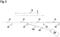
- FIG 4 shows a section of the transport device 15 with several transport belt elements 21, which are moved by means of the drive in the directions indicated by the arrows I, II. Edges 22 protruding from the undersides of the conveyor belt elements 21 form marking elements which are detected with the first sensor means.
- these first sensor elements 19 , 20 have two sensor elements 19 , 20 arranged one behind the other in the conveying direction of the transport device 15 .
- figure 5 shows a sensor arrangement with an ultrasonic sensor 19c with a transmitted ultrasonic wave 191 with a first specific frequency and a received ultrasonic wave 192 with a frequency changed by the speed of the transport device 15. Both the direction and the speed of the transport device 15 can be determined from the change in frequency of the received signal. Path information can be obtained by summing up the speed values.
- a radar sensor can also be provided instead of an ultrasonic sensor 19c.
- Path information is obtained by counting the pulsed sensor signals, and the speed of the transport device 15 is determined by the time intervals between the sensor signals.
- the transport direction of the transport device 15 is determined by evaluating the sequence of the sensor signals of the sensor elements 19, 20.
- Errors e.g. short circuit or oscillation
- the sensor elements 19, 20 can be detected by monitoring time intervals or time relationships and/or the time expectations of pulse widths, e.g. in relation to the period or time intervals, e.g. in relation to the period.
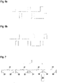
- figure 7 shows a modification of the embodiment according to FIG figure 5 .
- sensor element 19 In contrast to the embodiment according to figure 5 only sensor element 19 is provided, so that no direction detection is possible in this case.
- the evaluation of the time profile of the sensor signals 19 ( figure 8 ) is otherwise analogous to the embodiment according to Figures 6a, 6b .
- figure 9 shows a modification of the embodiment according to FIG figure 7 such that the conveyor belt elements 21 have different marking elements in the form of edges 22, 22'.
- the sensor 19 again has only one sensor element 19, direction detection is again possible on the basis of the different sensor signals generated by the different edges 22, 22'.
- Figure 10a shows the sensor signals of sensor element 19 for transport direction I.
- Figure 10b shows the sensor signals of sensor element 19 for transport direction II.
- the sensor signals are evaluated analogously to the embodiment of FIGS. 6a, 6b.
- figure 11 shows a variant of the transport device 15 with a drive in the form of a toothed belt drive 23 with a toothed belt 24.
- Marking elements in the form of elevations 25 or depressions 26 or material structure elements 28 can be provided on the toothed belt 24, which are scanned with the sensor 19.
- marking elements can also be provided on the drive axle 27 of the toothed belt drive 13 .
- Figures 12a - 12g show different embodiments of such marking elements
- the Figures 12a - 12d show a plan view of the front wheel portion of the drive axle 27, whereas the Figures 12e - 12g show longitudinal sections.
- Figures 12a, 12b show marking elements forming geometry structure elements in the form of elevations 25, while the figures show marking elements in the form of depressions 26.
- Figure 12g shows marking elements in the form of material structure elements 28. These form local areas with different material properties than the surrounding area, with these material structure elements 28 being able to be detected with the first sensor means.
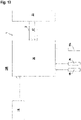
- figure 13 shows a further embodiment of the monitoring device 100 according to the invention in the form of a block diagram.
- figure 13 shows the safety sensor in the form of the light curtain 1 with a transmitter unit 30 having the transmitter 3 and a receiver unit 31 having the receiver 4.
- a controller is integrated in the receiver unit 31, which forms the evaluation unit and takes over the muting control.
- the controller 16 of the system 14 is connected to the receiver unit 31 and supplies path signals to the receiver unit 31.
- sensor signals generated by sensors 19, 19c, 20 are read into the receiver unit 31 in order to generate path signals and speed signals.
- the light curtain 1 again generates light beams 2b, which form the protective field 17 oriented in a vertical plane.
- figure 14 shows a first application example of the monitoring device 100 according to the invention.
- figure 14 shows the light curtain 1 on the transport device 15, the lower edge of the protective field 17 of the light curtain 1 adjoining the upper side of the transport device 15 forming a conveying surface.
- the protective field 17 is oriented in the vertical direction and thus perpendicular to the horizontal conveying surface.
- the beam axes formed by the light beams 2b of the light curtain 1 are denoted by 200-209.
- the beam axes 200 - 209 form the protective field 17.
- Packages 40 - 43 are transported in the direction of the light curtain 1 on the transport device 15 , as indicated by the arrow.
- the light curtain 1 is bridged for a period of time, ie muted, so that the packets 40 - 43 can pass through the light curtain 1 .
- the main criterion for identifying a permissible object is that it penetrates the lower edge of the protective field, in particular during a specific time window or travel window, ie interrupts the lowest beam axis 209 in the present case.
- the signals of the light curtain 1 are evaluated, controlled by a path window, in order to detect a permissible object.
- Path signals s1, s2 are used for path control, which are generated, for example, with sensors 19, 20 or safety controller 16 (FIG. 15).
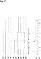
- figure 16 shows one according to the arrangement figure 14 largely corresponding arrangement. Unlike in the case of figure 14 now penetrates a package 42 in the protective field 17.
- the corresponding time diagrams for the structures 200 - 209 and the path signals s1, s2 of the sensors 19, 20 and the safety controller 16 shows figure 17 .
- the front contour of the package 40-43 entering the protective field 17 is detected within the travel window ⁇ s1.
- the beam axes 204, 205, 206, 207, 208 and in particular the bottom beam axis 209 are interrupted one after the other within the path window ⁇ s1.
- Package 42 is therefore considered a permissible object if the interruptions at the front edge are within a travel window ⁇ s1 and the absence of the interruptions at the rear edge are within a travel window ⁇ s2, so that light curtain 1 does not trigger the safety function.
- a corresponding monitoring of the rear contour of the package 42 takes place within the second travel window ⁇ s2.
- the transit time of an object 5 through the protective field 17 is monitored.
- the following requirements must be met cumulatively: within the entire travel window ⁇ s1, ⁇ s2 the bottom beam axis 209 of the light curtain 1 are interrupted.
- the entire passage ⁇ s can also be used as a criterion for a permissible object.
Abstract
Die Erfindung betrifft eine Überwachungseinrichtung (100) mit einem Lichtvorhang (1), welcher eine Anordnung von Lichtstrahlen (2) emittierenden Sendern (3) und eine Anordnung von Lichtstrahlen (2, 2b) empfangenden Empfängern (4) aufweist, wobei der Lichtvorhang (1) zur Objekterfassung innerhalb eines Schutzfelds (17) ausgebildet ist und mit einer Auswerteeinheit, in welcher bei Registrieren eines Objekts (5) im Schutzfeld (17) eine Sicherheitsfunktion auslösbar ist, und mit Mitteln zur Generierung einer Mutingfunktion, mittels derer die Sicherheitsfunktion überbrückbar ist. Die Mutingfunktion wird abhängig von Signalen des Lichtvorhangs (1) generiert. Eine Mutingfunktion wird nur dann generiert, wenn mit dem Lichtvorhang (1) eine sich bis zum unteren Rand des Schutzfelds (17) erstreckende Objektstruktur erkannt wird.The invention relates to a monitoring device (100) with a light curtain (1), which has an arrangement of transmitters (3) emitting light beams (2) and an arrangement of receivers (4) receiving light beams (2, 2b), the light curtain (1 ) is designed for object detection within a protective field (17) and with an evaluation unit in which a safety function can be triggered when an object (5) is registered in the protective field (17), and with means for generating a muting function, by means of which the safety function can be bypassed. The muting function is generated depending on signals from the light curtain (1). A muting function is only generated if the light curtain (1) detects an object structure that extends to the lower edge of the protective field (17).
Description
Die Erfindung betrifft eine Überwachungseinrichtung gemäß dem Oberbegriff des Anspruchs 1.The invention relates to a monitoring device according to the preamble of
Derartige Überwachungseinrichtungen werden im Bereich der Sicherheitstechnik eingesetzt, wobei generell mit dem Sicherheitssensor eine Gefahrenbereichsüberwachung einer gefahrbringenden Anlage durchgeführt wird, wobei der Begriff Anlage generell auch Maschinen, Roboter und dergleichen erfasst.Monitoring devices of this type are used in the field of safety technology, with the safety sensor generally being used to monitor the danger area of a hazardous installation, with the term installation also generally including machines, robots and the like.
Insbesondere wird die Überwachungseinrichtung als Zugangssicherung zu einem Gefahrenbereich einer Anlage eingesetzt, wobei der Zugang zu dem Gefahrenbereich über eine Fördereinrichtung erfolgt.In particular, the monitoring device is used to secure access to a hazardous area of a plant, with access to the hazardous area being provided via a conveying device.
Die Überwachungseinrichtung weist typischerweise als Sicherheitssensor einen Lichtvorhang auf, mit dem ein in einer Ebene liegendes Schutzfeld überwacht wird. Der Lichtvorhang generiert ein Schaltsignal, dessen Schaltzustände angeben ob ein Objekt im Schutzfeld vorhanden ist oder nicht. Wird mit dem Lichtvorhang ein Objekt im Schutzfeld detektiert wird durch das entsprechende Schaltsignal eine Sicherheitsfunktion ausgelöst. Beispielsweise wird mit dem Schaltsignal einer Steuereinheit der Anlage angesteuert, wodurch diese stillgesetzt wird, sodass keine Gefahren mehr von der Anlage ausgehen können.The monitoring device typically has a light curtain as a safety sensor, with which a protective field lying in one plane is monitored. The light curtain generates a switching signal whose switching states indicate whether an object is present in the protective field or not. If an object is detected in the protective field with the light curtain, a safety function is triggered by the corresponding switching signal. For example, the switch signal from a control unit activates the system, which shuts it down so that the system can no longer pose a risk.
Auf der Fördereinrichtung werden generell auch zulässige Objekte wie auf Paletten gelagerte Transportgüter der Anlage zugeführt, die zur Durchführung von Arbeitsvorgängen der Anlage benötigt werden. Da derartige zulässige Objekte nicht sicherheitskritisch sind, würde eine Auslösung der Sicherheitsfunktion bei der Bewegung zulässiger Objekte durch das Schutzfeld des Lichtvorhangs zu einem unnötigen Stillstand der Maschine führen.Permitted objects, such as transport goods stored on pallets, which are required for carrying out work processes in the system, are generally also fed to the system on the conveyor device. Since such permitted objects are not safety-critical, the safety function would be triggered at the movement of permissible objects through the protective field of the light curtain lead to an unnecessary standstill of the machine.
Um dies zu vermeiden sind bei bekannten Überwachungseinrichtungen in Förderrichtungen dem Sicherheitssensor Mutingsensoren vorgeordnet. Wird mit den Mutingsensoren ein Objekt als zulässiges Objekt erkannt, wird der Sicherheitssensor für eine vorgegebene Zeitdauer überbrückt, sodass dieser nicht mehr zur Auslösung der Sicherheitsfunktion führt, wenn das zulässige Objekt das Schutzfeld passiert.In order to avoid this, muting sensors are arranged upstream of the safety sensor in known monitoring devices in conveying directions. If an object is detected as a permissible object with the muting sensors, the safety sensor is bypassed for a specified period of time so that it no longer triggers the safety function when the permissible object passes the protective field.
Derartige Mutingsensoren sind typischerweise von Lichtschranken-/Lichttasteranordnungen gebildet. Mit derartigen Anordnungen können zulässige Objekte oft nicht zuverlässig erkannt werden.Such muting sensors are typically formed by light barrier/light scanner arrangements. Permitted objects often cannot be reliably detected with such arrangements.
Zudem ist nachteilig, dass die Abstimmung des Timings und der Auswertung der Signale der Mutingsensoren ungenau ist, da aus den Zeitpunkten der Objektdetektionen der Mutingsensoren anhand der Fördergeschwindigkeit hochgerechnet werden muss, welche Zeitspanne vergeht, bis das zulässige Objekt tatsächlich den Sicherheitssensor passiert hat. Die tatsächliche Fördergeschwindigkeit ist jedoch nicht immer exakt einstellbar oder exakt bekannt.Another disadvantage is that the coordination of the timing and the evaluation of the signals of the muting sensors is imprecise, since the time at which the object was detected by the muting sensors must be extrapolated based on the conveyor speed to determine the period of time until the permissible object has actually passed the safety sensor. However, the actual conveying speed cannot always be precisely set or exactly known.
Die
Der Erfindung liegt die Aufgabe zugrunde eine Überwachungseinrichtung der eingangs genannten Art bereitzustellen, welche bei konstruktiv einfachem Aufbau eine hohe Funktionalität und gleichzeitig eine hohe Funktionssicherheit aufweist.The object of the invention is to provide a monitoring device of the type mentioned at the outset which, with a structurally simple design, has a high level of functionality and at the same time a high level of functional reliability.
Zur Lösung dieser Aufgabe sind die Merkmale der unabhängigen Ansprüche vorgesehen. Vorteilhafte Ausführungsformen und zweckmäßige Weiterbildungen der Erfindung sind in den abhängigen Ansprüchen beschrieben.To solve this problem, the features of the independent claims are provided. Advantageous embodiments and expedient developments of the invention are described in the dependent claims.
Die Erfindung betrifft eine Überwachungseinrichtung mit einem Lichtvorhang, welcher eine Anordnung von Lichtstrahlen emittierenden Sendern und eine Anordnung von Lichtstrahlen empfangenden Empfängern aufweist, wobei der Lichtvorhang zur Objekterfassung innerhalb eines Schutzfelds ausgebildet ist und mit einer Auswerteeinheit, in welcher bei Registrieren eines Objekts im Schutzfeld eine Sicherheitsfunktion auslösbar ist und mit Mitteln zur Generierung einer Mutingfunktion, mittels derer die Sicherheitsfunktion überbrückbar ist. Die Mutingfunktion wird abhängig von Signalen des Lichtvorhangs generiert. Eine Mutingfunktion wird nur dann generiert, wenn mit dem Lichtvorhang eine sich bis zum unteren Rand des Schutzfelds erstreckende Objektstruktur erkannt wird.The invention relates to a monitoring device with a light curtain, which has an arrangement of transmitters emitting light beams and an arrangement of receivers receiving light rays, the light curtain being designed for object detection within a protective field and having an evaluation unit in which a safety function is performed when an object is registered in the protective field can be triggered and with means for generating a muting function, by means of which the safety function can be bridged. The muting function is generated depending on signals from the light curtain. A muting function is only generated if the light curtain detects an object structure that extends to the lower edge of the protective field.
Die Erfindung betrifft weiterhin ein entsprechendes Verfahren.The invention further relates to a corresponding method.
Die erfindungsgemäße Überwachungseinrichtung wird generell für eine Gefahrenbereichsüberwachung an einer gefahrbringenden Anlage eingesetzt. Besonders vorteilhaft wird die Überwachungseinrichtung als Zugangssicherung zu einem Gefahrenbereich eingesetzt, wobei der Zugang zum Gefahrenbereich insbesondere über eine Transporteinrichtung erfolgt.The monitoring device according to the invention is generally used for monitoring a danger zone in a hazardous installation. The monitoring device is used particularly advantageously to secure access to a danger area, with access to the danger area taking place in particular via a transport device.
Die erfindungsgemäße Überwachungseinrichtung bildet hierzu vorteilhaft ein Sicherheitssystem, das die Sicherheitsanforderungen für einen Einsatz in sicherheitsrelevanten Applikationen, insbesondere im Bereich des Personenschutzes erfüllt.For this purpose, the monitoring device according to the invention advantageously forms a safety system that meets the safety requirements for use in safety-relevant applications, in particular in the area of personal protection.
Die Komponenten des Sicherheitssystems weisen hierzu einen fehlersicheren Aufbau auf. Dies wird insbesondere durch einen redundanten, mehrkanaligen Aufbau der Auswerteeinheit des Sensors erreicht, so dass der Sensor einen Sicherheitssensor bildet.For this purpose, the components of the safety system have a fail-safe design. This is achieved in particular by a redundant, multi-channel design of the sensor's evaluation unit, so that the sensor forms a safety sensor.
Die Überwachungseinrichtung umfasst vorteilhaft eine Steuerung, die insbesondere zur Steuerung der mit dem Sensor überwachten Anlage dient. Die Steuerung ist dann als Sicherheitssteuerung ausgebildet und weist ebenfalls einen redundanten, mehrkanaligen Aufbau auf.The monitoring device advantageously includes a controller which is used in particular to control the system monitored by the sensor. The controller is then designed as a safety controller and also has a redundant, multi-channel structure.
Als zentrale Sicherheitskomponente der Überwachungseinrichtung ist der insbesondere als Sicherheitssensor ausgebildete Lichtvorhang vorgesehen, mit dem ein Schutzfeld überwacht wird, das vorteilhaft in einer Ebene verläuft.The light curtain, designed in particular as a safety sensor, is provided as the central safety component of the monitoring device, with which a protective field that advantageously runs in one plane is monitored.
Der Sicherheitssensor generiert ein binäres Schaltsignal, dessen Schaltzustände angeben, ob sich ein Objekt im Schutzfeld befindet oder nicht. Wird mit dem Sicherheitssensor ein Objekteingriff im Schutzfeld registriert, wird durch das Schaltsignal eine Sicherheitsfunktion ausgelöst, beispielsweise die Anlage stillgesetzt, sodass von dieser keine Gefahren mehr ausgehen können.The safety sensor generates a binary switching signal whose switching states indicate whether an object is in the protective field or not. If the safety sensor registers an object intrusion in the protective field, the switching signal triggers a safety function, for example shutting down the system so that it can no longer pose a risk.
Um ein unnötiges Stillsetzen der Anlage zu vermeiden, wenn zulässige Objekte, wie zum Beispiel der Anlage zuzuführende Transportgüter, durch das Schutzfeld in den Gefahrenbereich der Anlage gefördert sollen, ist eine Überbrückungsfunktion, das heißt eine Mutingfunktion vorgesehen. Bei aktivierter Mutingfunktion wird der Sicherheitssensor vollständig oder partiell überbrückt, das heißt gemutet, sodass das Transportgut das Schutzfeld passieren kann, ohne dass der Sicherheitssensor die Sicherheitsfunktion auslöst.A bridging function, i.e. a muting function, is provided to prevent the system from stopping unnecessarily when permissible objects, such as goods to be transported to the system, are to be conveyed through the protective field into the danger zone of the system. When the muting function is activated, the safety sensor is completely or partially bypassed, i.e. muted, so that the transported goods can pass through the protective field without the safety sensor triggering the safety function.
Bei einem vollständigen Muting ist der gesamte Sicherheitssensor überbrückt. Bei einem partiellen Muting wird nur ein Teil des Schutzfeldes überbrückt, insbesondere der Teil, in dem das zulässige Objekt erwartet beziehungsweise detektiert wird.In the case of a complete muting, the entire safety sensor is bypassed. In the case of partial muting, only part of the protective field is muted, in particular the part in which the permissible object is expected or detected.
Ein wesentlicher Vorteil der erfindungsgemäßen Überwachungseinrichtung besteht darin, dass anhand von Signalen des Lichtvorhangs selbst eine Mutingfunktion generiert werden kann, das heißt die Sicherheitsfunktion des Lichtvorhangs zur Gefahrenbereichsüberwachung wird überbrückt, das heißt stummgeschaltet. Zur Generierung der Mutingfunktion sind dabei keine externen Mutingsensoren erforderlich, was den konstruktiven und schaltungstechnischen Aufbau der Überwachungseinrichtung erheblich reduziert.An essential advantage of the monitoring device according to the invention is that a muting function can be generated using signals from the light curtain itself, ie the safety function of the light curtain for monitoring the danger area is bypassed, ie muted. No external muting sensors are required to generate the muting function, which considerably reduces the design and circuitry of the monitoring device.
Dabei ist zudem vorteilhaft, dass mit der erfindungsgemäßen Überwachungseinrichtung eine erheblich verbesserte und sicherere Mutingfunktion bereitgestellt wird.It is also advantageous that a significantly improved and safer muting function is provided with the monitoring device according to the invention.
Bei bekannten Überwachungseinrichtungen ist die Mutingfunktion dahingehend eingeschränkt, dass diese im Wesentlichen nur dann generiert werden kann, wenn ein zulässiges Objekt mit einer bestimmten Geometrie erkannt wird.In known monitoring devices, the muting function is limited in that it can essentially only be generated when a permissible object with a specific geometry is detected.
Bei der erfindungsgemäßen Überwachungseinrichtung wird die Funktionalität der Mutingfunktion erheblich erweitert. Dies wird auf überraschend einfache Weise dadurch erreicht, dass die Mutingfunktion dann generiert wird, wenn mit den Lichtvorhängen eine sich bis zum unteren Rand des Schutzfelds erstreckende Objektstruktur erkannt wird. Diese Objektstruktur muss sich über einen bestimmten, ausgedehnten Bereich erstrecken, das heißt es darf nicht nur ein lokaler, einmaliger Objekteingriff in das Schutzfeld sein.In the case of the monitoring device according to the invention, the functionality of the muting function is considerably expanded. This is achieved in a surprisingly simple manner in that the muting function is then generated when with an object structure extending to the lower edge of the protective field is detected by the light curtains. This object structure must extend over a specific, extensive area, i.e. it must not only be a local, one-time object intervention in the protective field.
Der Erfindung liegt dabei die Erkenntnis zugrunde, dass nicht gefahrbringende zulässige Objekte wie Transportgüter flächige Gegenstände sind, die auf einer Unterlage aufliegen. Durch die Objekterfassung im unteren Randbereich des Schutzfelds als Kriterium zur Erkennung zulässiger Objekte können diese sicher von sicherheitskritischen Objekten, insbesondere Personen sicher unterschieden werden.The invention is based on the finding that non-dangerous, permissible objects such as transport goods are flat objects that rest on a base. By detecting objects in the lower edge area of the protective field as a criterion for recognizing permissible objects, these can be reliably differentiated from safety-critical objects, in particular people.
Besonders vorteilhaft hierbei ist, dass mit dem Lichtvorhang auch mehrere überlagerte, das heißt gestapelte oder hintereinander oder nebeneinander angeordnete zulässige Objekte sicher erkannt und von sicherheitskritischen Objekten unterschieden werden können.It is particularly advantageous here that the light curtain can also be used to reliably detect a number of permissible objects that are superimposed, that is to say that are stacked or arranged one behind the other or next to one another, and can be distinguished from safety-critical objects.
Insbesondere wird eine Mutingfunktion generiert, wenn mit dem Lichtvorhang Strukturmerkmale von zulässigen Objekten erfasst werden.In particular, a muting function is generated when structural features of permissible objects are detected with the light curtain.
Dabei werden besonders vorteilhaft vordere und/oder hintere Strukturen von zulässigen Objekten als Kriterium für die Generierung der Mutingfunktion erfasst.In this case, front and/or rear structures of permissible objects are particularly advantageously detected as a criterion for generating the muting function.
Generell wird die Mutingfunktion so generiert, dass ein zulässiges Objekt den Lichtvorhang passiert, ohne dass dieser eine Sicherheitsfunktion generiert.In general, the muting function is generated in such a way that a permissible object passes the light curtain without it generating a safety function.
Gemäß einer besonders vorteilhaften Ausgestaltung der erfindungsgemäßen Überwachungseinrichtung ist eine Transporteinrichtung mit einer Förderfläche vorgesehen, auf welche zulässige Objekte transportiert werden. Der Lichtvorhang ist so an der Transporteinrichtung angeordnet, dass der untere Rand das Schutzfeld des Lichtvorhangs an die Förderfläche anschließt und in einem Neigungswinkel nach oder über diese hervorsteht.According to a particularly advantageous embodiment of the monitoring device according to the invention, a transport device is provided with a conveyor surface on which permissible objects are transported. The light curtain is arranged on the transport device in such a way that the lower edge connects the protective field of the light curtain to the conveying surface and protrudes at an angle of inclination towards or over it.
Vorteilhaft werden die zulässigen Objekte auf einer horizontalen Förderfläche transportiert, in welche der untere Bereich des Schutzfelds des Lichtvorhangs angrenzt, wobei das Schutzfeld vorteilhaft aber nicht zwingend senkrecht zur Förderfläche orientiert ist.The permissible objects are advantageously transported on a horizontal conveying surface, which is bordered by the lower area of the protective field of the light curtain, the protective field advantageously but not necessarily being oriented perpendicularly to the conveying surface.
Gemäß einer vorteilhaften Ausgestaltung ist jedem Sender der Lichtvorhänge ein Empfänger zugeordnet, wobei dieser Sender und Empfänger eine Strahlachse des Lichtvorhangs bildet, wobei bei freiem Schutzfeld die Lichtstrahlen der Sender aller Strahlachsen ungehindert auf den jeweils zugeordneten Empfänger treffen, und wobei bei einem Objekteingriff im Schutzfeld wenigstens eine Strahlachse unterbrochen ist.According to an advantageous embodiment, each transmitter of the light curtains is assigned a receiver, with this transmitter and receiver forming a beam axis of the light curtain, with the light beams of the transmitters of all beam axes impinging unhindered on the respectively assigned receiver when the protective field is free, and with at least a beam axis is interrupted.
Gemäß einer ersten Variante sind die Sender und Empfänger des Lichtvorhangs an gegenüberliegenden Rändern des Schutzfelds angeordnet.According to a first variant, the transmitter and receiver of the light curtain are arranged on opposite edges of the protective field.
Der Lichtvorhang arbeitet dann nach dem Prinzip einer Einweglichtschranke. In diesem Fall werden bei freiem Schutzfeld die Lichtstrahlen der einzelnen Strahlachsen direkt zum jeweiligen Sender auf den zugeordneten Empfänger geführt.The light curtain then works according to the principle of a one-way light barrier. In this case, if the protective field is free, the light beams of the individual beam axes are guided directly to the respective transmitter and the assigned receiver.
Gemäß einer zweiten Variante sind die Sender und Empfänger des Lichtvorhangs am selben Rand des Schutzfelds angeordnet, und der gegenüberliegende Rand des Schutzfelds ist von einem Reflektor begrenzt.According to a second variant, the emitters and receivers of the light curtain are arranged on the same edge of the protective field and the opposite edge of the protective field is delimited by a reflector.
Der Lichtvorhang bildet dann einen Reflexions-Lichtvorhang. In diesem Fall werden bei freiem Schutzfeld die Lichtstrahlen der einzelnen Strahlachsen vom jeweiligen Sender zum Reflektor geführt und von dort zum zugeordneten Empfänger reflektiert.The light curtain then forms a reflection light curtain. In this case, if the protective field is clear, the light beams of the individual beam axes are guided from the respective transmitter to the reflector and reflected from there to the assigned receiver.
Gemäß einer besonders vorteilhaften Ausführungsform weist die Überwachungseinrichtung Mittel zur Zeiterfassung und/oder Wegerfassung und/oder Erfassung der Transporteinrichtung von auf der Transporteinrichtung transportierten Objekte auf.According to a particularly advantageous embodiment, the monitoring device has means for recording the time and/or distance and/or recording of the transport device of objects transported on the transport device.
Vorteilhaft ist als Mittel zur Wegerfassung und/oder Transportrichtungserkennung wenigstens ein Sensorelement vorgesehen, mittels dessen Markierungselemente an der Transporteinrichtung erfassbar sind.At least one sensor element is advantageously provided as a means for detecting the path and/or the transport direction, by means of which the marking elements on the transport device can be detected.
Für eine Erkennung der Transportrichtung können beispielsweise zwei versetzte Sensorelemente und/oder richtungsabhängige Markierungselemente vorgesehen sein. Auch können Wegsignale von einer externen Steuerung, insbesondere in Form pulsförmiger Signale vorgegeben werden.For example, two offset sensor elements and/or direction-dependent marking elements can be provided for detecting the transport direction. Path signals can also be specified by an external controller, in particular in the form of pulsed signals.
Damit kann zeit- beziehungsweise ortsaufgelöst der Transport von Objekten durch das Schutzfeld erfasst werden, wodurch eine genaue und vollständige Information über die Struktur eines Objekts gewonnen wird, so dass genau und sicher analysiert werden kann, ob es sich um ein zulässiges Objekt handelt oder nicht.This allows the transport of objects through the protective field to be recorded in a time- or location-resolved manner, whereby precise and complete information about the structure of an object is obtained, so that it is possible to analyze precisely and reliably whether it is a permissible object or not.
Generell kann abhängig von einer zeitfenster- und/oder wegfenster- und/oder transportrichtungsüberwachten Objekterfassung mit dem Lichtvorhang eine Mutingfunktion generiert werden.In general, a muting function can be generated with the light curtain depending on a time window and/or distance window and/or direction of transport monitored object detection.
Anhand der Erkennung der Transportrichtung von Objekten kann erfasst werden, ob sich ein Objekt in Richtung des Gefahrenbereichs einer Anlage bewegt oder ob es sich aus dem Gefahrenbereich herausbewegt. Nur im ersten Fall ist eine Gefahrensituation gegeben, wenn das Objekt kein zulässiges Objekt ist, so dass dann der Lichtvorhang die Sicherheitsfunktion auslöst. Bewegt sich jedoch das Objekt aus dem Gefahrenbereich heraus, kann eine Mutingfunktion generiert werden und zwar selbst dann, wenn das Objekt kein zulässiges Objekt ist.By detecting the transport direction of objects, it can be determined whether an object is moving in the direction of the hazardous area of a system or whether it is moving out of the hazardous area. A dangerous situation only exists in the first case, if the object is not a permissible object, so that the light curtain then triggers the safety function. However, if the object moves out of the danger area, a muting function can be generated, even if the object is not a permissible object.
Dabei können unterschiedliche Strukturen von zulässigen Objekten zugelassen werden, die mit einer zeit- oder wegfensterüberwachten Objekterfassung erkannt werden können. So können beispielsweise auch Objekte, die Öffnungen wie Spalte oder Löcher aufweisen, zulässige Objekte sein. Derartige Öffnungen führen zu einem kurzfristigen Freiwerden einzelner Strahlachsen, was bei der zeit- oder wegfenstergesteuerten Objekterfassung als zulässig für die Erkennung eines zulässigen Objekts bewertet werden kann.Different structures of permissible objects can be permitted, which can be recognized with object detection that is monitored by time or distance window. For example, objects that have openings such as gaps or holes can also be permissible objects. Such openings lead to a short-term release of individual beam axes, which is or away-window-controlled object detection can be evaluated as permissible for the detection of a permissible object.
Gemäß einer vorteilhaften Ausführungsform wird eine Mutingfunktion nur dann generiert, wenn innerhalb eines vorgegebenen Zeitfensters oder Wegfensters durch Registrieren unterbrochener Strahlachsen eine hintere geschlossene Struktur und/oder eine vordere geschlossene Struktur eines Objekts erkannt wird.According to an advantageous embodiment, a muting function is only generated if a rear closed structure and/or a front closed structure of an object is detected within a predetermined time window or path window by registering interrupted beam axes.
Durch die weg- oder zeitaufgelöste Erfassung können hintere und vordere Strukturen von Objekten genau analysiert werden und dadurch zulässige Objekte sicher erkannt und von nicht zulässigen Objekten unterschieden werden.The rear and front structures of objects can be precisely analyzed by the displacement or time-resolved detection, and thus permissible objects can be reliably recognized and differentiated from objects that are not permissible.
Durch die Größe der Weg- oder Zeitfenster kann auch die Art der zu erfassenden Objektstrukturen flexibel vorgegeben werden. So können mit kleinen Weg- oder Zeitfenster insbesondere selektiv vertikale, das heißt entlang der Ebene des Schutzfelds verlaufende Objektstrukturen erkannt werden. Dies ist dann vorteilhaft, wenn Seitenflächen von quaderförmigen Objekten erkannt werden sollen.The type of object structures to be recorded can also be flexibly specified by the size of the path or time window. In this way, vertical object structures, i.e. object structures running along the plane of the protective field, can be selectively detected with small distance or time windows. This is advantageous if side surfaces of cuboid objects are to be recognized.
Zweckmäßig wird dabei die Größe der Weg- oder Zeitfenster an die Fördergeschwindigkeit der Transporteinrichtung angepasst.The size of the path or time window is expediently adapted to the conveying speed of the transport device.
Weiter vorteilhaft lassen zusätzliche oder entfallende Strahlunterbrechungen außerhalb des Zeitfensters oder Wegfensters die Mutingfunktion unbeeinträchtigt.Further advantageously, additional or omitted beam interruptions outside the time window or distance window leave the muting function unimpaired.
Dies führt zu einer Reduzierung von Störeinflüssen, da nur während der gegebenenfalls eng begrenzten Weg- oder Zeitfenster registrierte Strahlen Unterbrechungen des Lichtvorhangs zur Erfassung von zulässigen Objekten herangezogen werden, jedoch geänderte Strahlunterbrechungen außerhalb des jeweiligen Weg- oder Zeitfensters ausgeblendet werden.This leads to a reduction in interference, since beam interruptions of the light curtain that are registered only during the possibly narrowly limited path or time window are used to detect permissible objects, but changed beam interruptions outside of the respective path or time window are masked out.
Gemäß einer vorteilhaften Ausführungsform werden zulässige Objekte eingelernt oder vorgegeben.According to an advantageous embodiment, permissible objects are taught or specified.
Ein Einlernvorgang kann beispielsweise durch ein Enable Signal einer externen Steuerung, insbesondere der Steuerung der zu überwachenden Anlage oder der Transporteinrichtung. Auch kann ein Einlernen nach dem Einschalten der Transporteinrichtung erfolgen, so dass dann zulässige Objekte bei einem ersten Durchgang durch den Lichtvorhang eingelernt werden.A learning process can be carried out, for example, by an enable signal from an external controller, in particular the controller of the system to be monitored or the transport device. Teaching can also take place after the transport device has been switched on, so that permissible objects are then taught in during a first passage through the light curtain.
Gemäß einer weiteren vorteilhaften Ausführungsform werden minimal und/oder maximale Größen von zulässigen Objekten eingelernt oder vorgegeben.According to a further advantageous embodiment, minimum and/or maximum sizes of permissible objects are taught or specified.
Dadurch wird auf einfache Weise die Anzahl der möglichen zulässigen Objekte eingegrenzt werden.This will easily limit the number of possible allowed objects.
Weiter vorteilhaft werden minimale und/oder maximale Durchlaufdauern von zulässigen Objekten eingelernt oder vorgegeben.Further advantageously, minimum and/or maximum throughput times of permissible objects are taught or specified.
Diese Vorgabe erfolgt zweckmäßig abhängig von der Transportgeschwindigkeit der Transporteinrichtung und der Verbreitung der Größen der zulässigen Obj ekte.This specification is expediently dependent on the transport speed of the transport device and the spread of the sizes of the permissible objects.
Gemäß einer weiteren vorteilhaften Ausführungsform werden Ränder von zulässigen Objekten innerhalb vorgegebener Toleranzbereiche oder durch Randstrahlen bestimmter Unschärfebereiche erkannt.According to a further advantageous embodiment, edges of permissible objects are recognized within predetermined tolerance ranges or blurred areas determined by marginal rays.
Insbesondere aufgrund von Unregelmäßigkeiten bei der Förderung von zulässigen Objekten, beispielsweise durch Vibrationen der Förderfläche der Transporteinrichtung kann bei Durchgang durch den Lichtvorhang die Höhe der zulässigen Objekte schwanken.In particular due to irregularities in the conveyance of permissible objects, for example due to vibrations of the conveying surface of the transport device, the height of the permissible objects can fluctuate when they pass through the light curtain.
Um auch bei derartigen Störeinflüssen noch eine zuverlässige Erkennung von zulässigen Objekten zu gewährleisten, können Toleranzbereiche vorgegeben werden, innerhalb derer Randkonturen von zulässigen Objekten erkannt werden müssen, um diese als solche zu identifizieren. Die Toleranzbereiche geben dann einen Bereich von unterbrochenen Strahlachsen vor, die der Detektion einer Randkontur des zulässigen Objekts entsprechen.In order to ensure reliable detection of permissible objects even with such interference, tolerance ranges can be specified within which edge contours of permissible objects must be detected in order to identify them as such. The tolerance ranges then give proposes a range of interrupted beam axes corresponding to the detection of an edge contour of the allowed object.
Des Weiteren können auch durch Randstrahlen definierte Unschärfebereiche zur Detektion von Randkonturen von zulässigen Objekten vorgegeben werden. Üblicherweise werden die Empfangssignale der Empfänger mit nur einem Schwellwert bewertet um festzustellen, ob die jeweilige Strahlachse unterbrochen ist oder nicht. Durch das Vorsehen mehrerer Schwellwerte kann zudem beurteilt werden, ob einzelne Strahlachsen nur teilweise unterbrochen sind, das heißt in diesem Fall wird ein Teil der Lichtstrahlen von einem Objekt unterbrochen.Furthermore, blurred areas defined by edge rays can also be specified for the detection of edge contours of permissible objects. The received signals of the receivers are usually evaluated with only one threshold value in order to determine whether the respective beam axis is interrupted or not. By providing a plurality of threshold values, it is also possible to assess whether individual beam axes are only partially interrupted, ie in this case part of the light beams is interrupted by an object.
Durch die Vorgabe der Unschärfebereiche darf während der Durchfahrt eines zulässigen Objekts durch den Lichtvorhang bei der Detektion von Randkonturen des zulässigen Objekts eine bestimmte Anzahl derartiger Randstrahlen vorliegen.Due to the specification of the unsharp areas, a specific number of such marginal rays may be present when a permissible object is being driven through the light curtain when detecting edge contours of the permissible object.
Je nach Anwendungsfall kann der Lichtvorhang mit einer reduzierten Auflösung betrieben werden.Depending on the application, the light curtain can be operated with a reduced resolution.
Bei einer reduzierten Auflösung wird ein Objekt nur dann erkannt, wenn die Lichtstrahlen mehrere zusammenhängender Strahlachsen unterbrochen werden.With a reduced resolution, an object is only recognized if the light beams are interrupted by several connected beam axes.
Die Erfindung wird im Folgenden anhand der Zeichnungen erläutert. Es zeigen:
- Figur 1:
- Erstes Ausführungsbeispiel eines Lichtvorhangs für die erfindungsgemäße Überwachungseinrichtung.
- Figur 2:
- Zweites Ausführungsbeispiel eines Lichtvorhangs für die erfindungsgemäße Überwachungseinrichtung.
- Figur 3:
- Ausführungsbeispiel der erfindungsgemäßen Überwachungseinrichtung.
- Figur 4:
- Erstes Beispiel einer Wegerfassung an einer Transporteinrichtung der Überwachungseinrichtung gemäß
Figur 4 mittels Sensormittel. - Figur 5:
- Beispiel einer Geschwindigkeits-/Wegerfassung mit Radar-, Schall-, oder Optik-Wellen.
- Figur 6a,b:
- Zeitabhängige Signalverläufe der Sensorsignale der Sensormittel der Anordnung gemäß
Figur 5 - Figur 7:
- Zweites Beispiel einer Wegerfassung an einer Transporteinrichtung der Überwachungseinrichtung gemäß
Figur 4 mittels Sensormittel. - Figur 8:
- Zeitabhängige Signalverläufe der Sensorsignale der Sensormittel der Anordnung gemäß
Figur 7 . - Figur 9:
- Drittes Beispiel einer Wegerfassung an einer Transporteinrichtung der Überwachungseinrichtung gemäß
Figur 4 mittels Sensormittel. - Figur 10a,b:
- Zeitabhängige Signalverläufe der Sensorsignale der Sensormittel gemäß
Figur 9 . - Figur 11:
- Beispiel eines Zahnriemenantriebs für die Referenzelement der Überwachungseinrichtung gemäß
Figur 4 Figur 12a-g:- Unterschiedliche Markierungselemente für die Anordnung gemäß
Figur 11 . - Figur 13:
- Blockschaltbild eines weiteren Ausführungsbeispiels der Überwachungseinrichtung.
- Figur 14:
- Erstes Applikationsbeispiel für die
Überwachungseinrichtung gemäß Figur 3 bzw.Figur 13 - Figur 15:
- Zeitdiagramme für die
Anordnung gemäß Figur 14 . - Figur 16:
- Zweites Applikationsbeispiel für die
Überwachungseinrichtung gemäß Figur 3 bzw.Figur 13 - Figur 17:
- Zeitdiagramme für die
Anordnung gemäß Figur 16 .
- Figure 1:
- First embodiment of a light curtain for the monitoring device according to the invention.
- Figure 2:
- Second embodiment of a light curtain for the monitoring device according to the invention.
- Figure 3:
- Embodiment of the monitoring device according to the invention.
- Figure 4:
- First example of a path detection on a transport device according to the monitoring device
figure 4 by means of sensor means. - Figure 5:
- Example of a speed/displacement detection with radar, sound or optical waves.
- Figure 6a,b:
- Time-dependent signal curves of the sensor signals of the sensor means according to the arrangement
figure 5 . - Figure 7:
- Second example of path detection on a transport device according to the monitoring device
figure 4 by means of sensor means. - Figure 8:
- Time-dependent signal curves of the sensor signals of the sensor means according to the arrangement
figure 7 . - Figure 9:
- Third example of path detection on a transport device according to the monitoring device
figure 4 by means of sensor means. - Figure 10a,b:
- Time-dependent waveforms of the sensor signals of the sensor means according to
figure 9 . - Figure 11:
- Example of a toothed belt drive for the reference element of the monitoring device according to
figure 4 . - Figure 12a-g:
- Different marking elements for the arrangement according to
figure 11 . - Figure 13:
- Block diagram of a further exemplary embodiment of the monitoring device.
- Figure 14:
- First application example for the monitoring device according to
figure 3 or.figure 13 . - Figure 15:
- Timing diagrams for the arrangement according to
figure 14 . - Figure 16:
- Second application example for the monitoring device according to
figure 3 or.figure 13 . - Figure 17:
- Timing diagrams for the arrangement according to
figure 16 .
Der Lichtvorhang 1 weist in einem ersten Gehäuse 12a eine Reihenanordnung von Lichtstrahlen 2 emittierenden Sendern 3 und in einem zweiten Gehäuse 12b eine Reihenanordnung von Empfängern 4 auf. Die Lichtstrahlen 2 spannen einen flächigen Überwachungsbereich auf, der in einer vertikalen Ebene orientiert ist.The
Die Sender 3 werden einzeln nacheinander zyklisch mittels einer nicht dargestellten Sendersteuerung aktiviert. Die Empfänger 4 werden in bekannter Weise optisch auf die Sender 3 synchronisiert.The
Die in den Empfängern 4 generierten Empfangssignale werden in einer nicht dargestellten Auswerteeinheit zur Generierung eines binären Schaltsignals ausgewertet. Die Schaltzustände des Schaltsignals geben an, ob sich ein Objekt 5 im Überwachungsbereich befindet oder nicht. Bei freiem Überwachungsbereich treffen die Lichtstrahlen 2 aller Sender 3 ungehindert auf den zugeordneten Empfänger 4. Bei einem Objekteingriff im Überwachungsbereich werden durch das Objekt 5 die Lichtstrahlen 2 wenigstens eines Senders 3 unterbrochen. Zur Erfüllung der sicherheitstechnischen Anforderungen weist die Auswerteeinheit einen redundanten, vorzugsweise zweikanaligen Aufbau auf.The received signals generated in the
Generell kann der Lichtvorhang 1 gemäß
Der Lichtvorhang 1 weist in einem ersten Gehäuse 12 eine Reihenanordnung von Lichtstrahlen 2 emittierenden Sendern 3 und im gleichen Gehäuse 12 einen Empfänger 4 auf. Generell kann auch eine Reihenanordnung von Empfängern 4 vorgesehen sein.The
Im gegenüberliegenden Gehäuse 12' sind Umlenkspiegel 38 angebracht, die die Lichtstrahlen 2 der Sender 3 zu Lichtstrahlen 2b für den Empfänger 4 umlenken. Die Lichtstrahlen 2, 2b spannen einen flächigen Überwachungsbereich auf, der in einer vertikalen Ebene orientiert ist und damit senkrecht zur horizontalen Oberfläche des Förderbands der Fördereinrichtung verläuft.In the opposite housing 12 'deflecting mirrors 38 are attached, which deflect the
Die Sender 3 werden einzeln nacheinander zyklisch mittels einer nicht dargestellten Sendersteuerung aktiviert. Der Empfänger 4 wird in bekannter Weise elektrisch oder optisch auf die Sender 3 synchronisiert.The
Die in den Empfängern 4 generierten Empfangssignale werden in einer nicht dargestellten Auswerteeinheit zur Generierung eines binären Schaltsignals ausgewertet. Die Schaltzustände des Schaltsignals geben an, ob sich ein Objekt 5 im Überwachungsbereich befindet oder nicht. Bei freiem Überwachungsbereich treffen die Lichtstrahlen 2, 2b aller Sender 3 ungehindert auf den zugeordneten Empfänger 4. Bei einem Objekteingriff im Überwachungsbereich werden durch das Objekt 5 die Lichtstrahlen 2, 2b wenigstens eines Senders 3 unterbrochen. Zur Erfüllung der sicherheitstechnischen Anforderungen weist die Auswerteeinheit einen redundanten, vorzugsweise zweikanaligen Aufbau auf.The received signals generated in the
Der Zugang zu dem Gefahrenbereich 13 wird mittels eines Lichtvorhangs 1 überwacht. Mit den Lichtstrahlen 2, 2b des Lichtvorhangs 1 wird ein Schutzfeld 17 überwacht.Access to the
Dringt ein Objekt 5 in das Schutzfeld 17 ein, wird ein binäres Schaltsignal mit einem Schaltzustand generiert, das zur Auslösung einer Sicherheitsfunktion führt. Im vorliegenden Fall wird das Schaltsignal an die Sicherheitssteuerung 16 ausgegeben. Die Sicherheitsfunktion ist dadurch gebildet, dass die Anlage 14 stillgesetzt wird.If an
Auf der Transporteinrichtung 15 werden zulässige Objekte in Form von Transportgütern 18 in einer Transportrichtung I transportiert. Diese zulässigen Objekte sind nicht gefahrbringend und sollen durch das Schutzfeld 17 der Lichtvorhänge hindurch zur Anlage 14 geführt werden, ohne dass die Sicherheitsfunktion ausgelöst wird.Permissible objects in the form of
Hierzu ist eine Überbrückungsfunktion, das heißt Mutingfunktion vorgesehen, mittels derer der Sensor 1 überbrückt wird, so dass er keine Sicherheitsfunktion auslöst, wenn ein Transportgut 18 das Schutzfeld 17 passiert.For this purpose, a bridging function, that is to say a muting function, is provided, by means of which the
Dabei kann das gesamte Schutzfeld 17 überbrückt werden oder, bei einem partiellen Muting, nur der Teil 17' des Schutzfelds 17, innerhalb dessen das Transportgut 18 vorhanden ist. Bei variierenden Konturen der Transportgüter variiert auch der überbrückte Teil 17' des Schutzfelds 17.The entire
Vorteilhaft wird die Mutingfunktionen abhängig von einer mit Sensormitteln durchgeführten Wegerfassung gesteuert oder überwacht.Advantageously, the muting function is controlled or monitored as a function of a path detection carried out using sensors.
Generell sind die Sensorelemente 19, 20 in Form von optischen, magnetischen, induktiven oder kapazitiven Sensormitteln ausgebildet.In general, the
Dabei generieren die Sensorelemente 19, 20 vorzugsweise pulsförmige Sensorsignale.In this case, the
Somit kann anhand von Sensorsignalen der Sensorelemente 19, 20 die Geschwindigkeit oder Wegstrecken der Transporteinrichtung 15 ermittelt werden.The speed or distances of the
In einer Variante können die Sensorelemente 19, 20 als Radarsensoren, optische Sensoren oder Ultraschallsensoren 19c ausgebildet sein. Geschwindigkeitssignale und Richtungssignale können damit durch Auswertung des Dopplereffekts, also der Frequenzänderung der reflektierten Wellen gegenüber der ausgesendeten Welle ermittelt werden. Aus dem so ermittelten Geschwindigkeitssignal können Weginformationen durch Aufsummierung des Geschwindigkeitssignals ermittelt werden.In a variant, the
Bei der Abtastung der Markierungselemente werden für die Förderrichtung I die in
Durch Zählen der pulsförmigen Sensorsignale wird eine Weginformation erhalten, durch die zeitlichen Abstände der Sensorsignale wird die Geschwindigkeit der Transporteinrichtung 15 ermittelt. Durch Auswerten der Reihenfolgen der Sensorsignale der Sensorelemente 19, 20 ergibt sich die Transportrichtung der Transporteinrichtung 15.Path information is obtained by counting the pulsed sensor signals, and the speed of the
Durch Überwachung von zeitlichen Abständen oder zeitlicher Verhältnisse und/oder der zeitliche Erwartungshaltung an Pulsbreiten z.B. im Verhältnis zur Periode oder zeitlichen Abstände z.B. im Verhältnis zur Periode können Fehler (z.B. Kurzschluss oder Oszillation) in den Sensorelementen 19, 20 aufgedeckt werden.Errors (e.g. short circuit or oscillation) in the
Die Auswertung der Sensorsignale erfolgt analog zur Ausführungsform der Figuren 6a, 6b.The sensor signals are evaluated analogously to the embodiment of FIGS. 6a, 6b.
Alternativ können auch Markierungselemente an der Antriebsachse 27 des Zahnriemenantriebs 13 vorgesehen sein.Alternatively, marking elements can also be provided on the
Die
Die
Die Steuerung 16 der Anlage 14 ist an die Empfängereinheit 31 angeschlossen und liefert Wegsignale an die Empfängereinheit 31.The
Weiterhin werden von Sensoren 19, 19c, 20 generierte Sensorsignale in die Empfängereinheit 31 eingelesen um Wegsignale und Geschwindigkeitssignale zu generieren.Furthermore, sensor signals generated by
Wie aus
Die von den Lichtstrahlen 2b des Lichtvorhangs 1 gebildeten Strahlachsen sind mit 200 - 209 bezeichnet. Die Strahlachsen 200 - 209 bilden das Schutzfeld 17.The beam axes formed by the
Auf der Transporteinrichtung 15 werden, wie mit dem Pfeil gekennzeichnet, Pakete 40 - 43 in Richtung des Lichtvorhangs 1 transportiert.Packages 40 - 43 are transported in the direction of the
Für den Fall, dass die Pakete 40 - 43 als zulässiges Objekt vom Lichtvorhang 1 erkannt werden, wird der Lichtvorhang 1 für eine Zeitdauer überbrückt, das heißt gemutet, so dass die Pakete 40 - 43 am Lichtvorhang 1 passieren können.In the event that the packets 40 - 43 are recognized as a permissible object by the
Als Hauptkriterium für die Identifizierung eines zulässigen Objekts ist es erfindungsgemäß, dass dieses, insbesondere während eines bestimmten Zeitfensters oder Wegfensters, in den unteren Schutzfeld-Rand eindringt, also im vorliegenden Fall die unterste Strahlachse 209 unterbricht.According to the invention, the main criterion for identifying a permissible object is that it penetrates the lower edge of the protective field, in particular during a specific time window or travel window, ie interrupts the
Dabei wird die Erkenntnis ausgenutzt, dass die zulässigen Objekte wie die dargestellten Pakete 40 - 43, flächig mit geschlossenen Konturen auf der Förderfläche der Transporteinrichtung 15 aufliegen, wodurch die unterste Strahlachse 209 bei Durchlauf der Pakete 40 - 43 auch das Schutzfeld 17 unterbrochen wird.This exploits the knowledge that the permissible objects, such as the packages 40 - 43 shown, lie flat with closed contours on the conveying surface of the
Damit können nicht gefahrbringende zulässige Objekte sicher von sicherheitskritischen Objekten unterschieden, wie zum Beispiel der in
Im vorliegenden Fall erfolgt eine Wegfenster- gesteuerte Auswertung der Signale des Lichtvorhangs 1 um ein zulässiges Objekt zu erkennen.In the present case, the signals of the
Für die Wegsteuerung werden Wegsignale s1, s2 verwendet, die zum Beispiel mit den Sensoren 19,20 oder der Sicherheitssteuerung 16 generiert werden (Figur 15).Path signals s1, s2 are used for path control, which are generated, for example, with
Bei der in
Da innerhalb des Wegfensters Δs (das mit der ersten Unterbrechung einer Strahlachse 205 beginnt) die unterste Strahlachse 209 nicht unterbrochen wird, liegt kein zulässiges Objekt vor.Since the
Damit führt der Eingriff des Arms 44 in das Schutzfeld 17 im Lichtvorhang 1 zur Generierung eines Schaltsignals und damit zum Auslösen der Sicherheitsfunktion.The intervention of the
Wie
Eine entsprechende Überwachung der hinteren Kontur des Pakets 42 erfolgt innerhalb des zweiten Wegfensters Δs2.A corresponding monitoring of the rear contour of the
Schließlich erfolgt eine Überwachung der Durchlaufzeit eines Objekts 5 durch das Schutzfeld 17. Als Kriterium dafür, dass ein Objekt 5 als zulässiges Objekt identifiziert wird, das zur Generierung der Mutingfunktion führt, müssen kumulativ folgende Forderungen erfüllt sein: Innerhalb der gesamten Wegfenster Δs1, Δs2 muss die unterste Strahlachse 209 des Lichtvorhangs 1 unterbrochen werden. Zudem muss die Durchlaufzeit des Objekts 5 durch das Schutzfeld 17 innerhalb des Zeitfensters Δt (
- (1)(1)
- Lichtvorhanglight curtain
- (2)(2)
- Lichtstrahlenrays of light
- (2b)(2 B)
- Lichtstrahlenrays of light
- (3)(3)
- SenderChannel
- (4)(4)
- Empfängerrecipient
- (5)(5)
- Objektobject
- (12)(12)
- Gehäusehousing
- (12')(12')
- Gehäusehousing
- (12a)(12a)
- Gehäusehousing
- (12b)(12b)
- Gehäusehousing
- (13)(13)
- Gefahrenbereichdanger area
- (14)(14)
- Anlageinvestment
- (15)(15)
- Transporteinrichtungtransport device
- (16)(16)
- Sicherheitssteuerungsafety control
- (17)(17)
- Schutzfeldprotective field
- (17')(17')
- Teilschutzfeldpartial protective field
- (18)(18)
- Transportgutcargo
- (19)(19)
- Sensorelementsensor element
- (19c)(19c)
- Ultraschallsensorultrasonic sensor
- (20)(20)
- Sensorelementsensor element
- (21)(21)
- Transportbandelementeconveyor elements
- (22)(22)
- Kanteedge
- (22')(22')
- Kanteedge
- (23)(23)
- Zahnriemenantriebtoothed belt drive
- (24)(24)
- Zahnriementiming belt
- (25)(25)
- Erhebungelevation
- (26)(26)
- Vertiefungdeepening
- (27)(27)
- Antriebsachsedrive axle
- (28)(28)
- Materialstrukturelementmaterial structure element
- (30)(30)
- Sendereinheittransmitter unit
- (31)(31)
- Empfängereinheitreceiver unit
- (38)(38)
- Umlenkspiegeldeflection mirror
- (40)(40)
- Paketpackage
- (41)(41)
- Paketpackage
- (42)(42)
- Paketpackage
- (43)(43)
- Paketpackage
- (44)(44)
- Armpoor
- (100)(100)
- Überwachungseinrichtungmonitoring device
- (191)(191)
- Ultraschallwelleultrasonic wave
- (192)(192)
- Ultraschallwelleultrasonic wave
- (200)(200)
- Strahlachsebeam axis
- (201)(201)
- Strahlachsebeam axis
- (202)(202)
- Strahlachsebeam axis
- (203)(203)
- Strahlachsebeam axis
- (204)(204)
- Strahlachsebeam axis
- (205)(205)
- Strahlachsebeam axis
- (206)(206)
- Strahlachsebeam axis
- (207)(207)
- Strahlachsebeam axis
- (208)(208)
- Strahlachsebeam axis
- (209)(209)
- Strahlachsebeam axis
Claims (18)
Priority Applications (1)
| Application Number | Priority Date | Filing Date | Title |
|---|---|---|---|
| EP20197956.4A EP3974699A1 (en) | 2020-09-24 | 2020-09-24 | Monitoring device |
Applications Claiming Priority (1)
| Application Number | Priority Date | Filing Date | Title |
|---|---|---|---|
| EP20197956.4A EP3974699A1 (en) | 2020-09-24 | 2020-09-24 | Monitoring device |
Publications (1)
| Publication Number | Publication Date |
|---|---|
| EP3974699A1 true EP3974699A1 (en) | 2022-03-30 |
Family
ID=72644101
Family Applications (1)
| Application Number | Title | Priority Date | Filing Date |
|---|---|---|---|
| EP20197956.4A Pending EP3974699A1 (en) | 2020-09-24 | 2020-09-24 | Monitoring device |
Country Status (1)
| Country | Link |
|---|---|
| EP (1) | EP3974699A1 (en) |
Citations (4)
| Publication number | Priority date | Publication date | Assignee | Title |
|---|---|---|---|---|
| EP1331433A2 (en) * | 2002-01-25 | 2003-07-30 | Keyence Corporation | Multi-optical-path photoelectric safety apparatus |
| EP1344973A2 (en) * | 2002-03-12 | 2003-09-17 | REER S.p.A. | Column for a photoelectric barrier provided with muting sensors |
| DE102007033766B4 (en) | 2007-07-18 | 2009-11-26 | Leuze Lumiflex Gmbh + Co. Kg | light Curtain |
| EP2474960A1 (en) * | 2009-08-31 | 2012-07-11 | Omron Corporation | Multiple-optical-axis photoelectric sensor, and safety management system using same |
-
2020
- 2020-09-24 EP EP20197956.4A patent/EP3974699A1/en active Pending
Patent Citations (4)
| Publication number | Priority date | Publication date | Assignee | Title |
|---|---|---|---|---|
| EP1331433A2 (en) * | 2002-01-25 | 2003-07-30 | Keyence Corporation | Multi-optical-path photoelectric safety apparatus |
| EP1344973A2 (en) * | 2002-03-12 | 2003-09-17 | REER S.p.A. | Column for a photoelectric barrier provided with muting sensors |
| DE102007033766B4 (en) | 2007-07-18 | 2009-11-26 | Leuze Lumiflex Gmbh + Co. Kg | light Curtain |
| EP2474960A1 (en) * | 2009-08-31 | 2012-07-11 | Omron Corporation | Multiple-optical-axis photoelectric sensor, and safety management system using same |
Similar Documents
| Publication | Publication Date | Title |
|---|---|---|
| EP1548351B1 (en) | Device for monitoring an area at a machine | |
| EP1544535B1 (en) | Device for the surveillance of the reach area in a worktool | |
| EP2180348B1 (en) | Safety light curtain and corresponding method for monitoring a protection area | |
| EP1046925B1 (en) | Optoelectronic device | |
| EP1089030A2 (en) | Device and method for monitoring a protection zone | |
| DE4422497A1 (en) | Opto-electronic detector of objects moving in region under surveillance | |
| EP3910230A1 (en) | Monitoring device | |
| EP2306063B2 (en) | Security sensor | |
| DE10312972B3 (en) | Optical sensor for detecting objects within surveillance zone with selection of different protected fields within latter by activation signals received via bidirectional data communications interface | |
| EP3885635B1 (en) | Monitoring device for securing access to a danger zone with a safety sensor | |
| DE19828000C2 (en) | Method for optoelectronic monitoring of a protected area | |
| EP3415804B1 (en) | Safety device | |
| EP1826589B1 (en) | Optical sensor for monitoring a protection zone | |
| EP3633413B1 (en) | Safety arrangement | |
| EP3974699A1 (en) | Monitoring device | |
| EP3945237A1 (en) | Monitoring device and method for operating same | |
| EP3919801A1 (en) | Monitoring device | |
| EP3910227B1 (en) | Monitoring device and method for operating same | |
| DE102017119283B4 (en) | Sensor system | |
| EP3910228B1 (en) | Monitoring device and method for operating same | |
| EP3910229A1 (en) | Monitoring device | |
| EP4047256A1 (en) | Monitoring device and method for protecting a hazardous area by means of a monitoring device | |
| EP3945238B1 (en) | Monitoring device and method for operating same | |
| EP3875993B1 (en) | Sensor assembly and method for operating a sensor assembly | |
| EP4151899A1 (en) | Monitoring device |
Legal Events
| Date | Code | Title | Description |
|---|---|---|---|
| PUAI | Public reference made under article 153(3) epc to a published international application that has entered the european phase |
Free format text: ORIGINAL CODE: 0009012 |
|
| STAA | Information on the status of an ep patent application or granted ep patent |
Free format text: STATUS: REQUEST FOR EXAMINATION WAS MADE |
|
| 17P | Request for examination filed |
Effective date: 20210511 |
|
| AK | Designated contracting states |
Kind code of ref document: A1 Designated state(s): AL AT BE BG CH CY CZ DE DK EE ES FI FR GB GR HR HU IE IS IT LI LT LU LV MC MK MT NL NO PL PT RO RS SE SI SK SM TR |