EP4047221A1 - Verbesserte ergonomische befestigungsklammer - Google Patents
Verbesserte ergonomische befestigungsklammer Download PDFInfo
- Publication number
- EP4047221A1 EP4047221A1 EP21201530.9A EP21201530A EP4047221A1 EP 4047221 A1 EP4047221 A1 EP 4047221A1 EP 21201530 A EP21201530 A EP 21201530A EP 4047221 A1 EP4047221 A1 EP 4047221A1
- Authority
- EP
- European Patent Office
- Prior art keywords
- fastening clip
- body portion
- end region
- clip according
- clip
- Prior art date
- Legal status (The legal status is an assumption and is not a legal conclusion. Google has not performed a legal analysis and makes no representation as to the accuracy of the status listed.)
- Pending
Links
- 239000000463 material Substances 0.000 claims description 9
- 230000006378 damage Effects 0.000 claims description 7
- 238000005452 bending Methods 0.000 claims description 2
- 238000004080 punching Methods 0.000 claims description 2
- 239000002184 metal Substances 0.000 description 8
- 229910000975 Carbon steel Inorganic materials 0.000 description 2
- 230000001174 ascending effect Effects 0.000 description 2
- 230000008901 benefit Effects 0.000 description 2
- 239000010962 carbon steel Substances 0.000 description 2
- 238000010276 construction Methods 0.000 description 2
- 238000003780 insertion Methods 0.000 description 2
- 230000037431 insertion Effects 0.000 description 2
- 238000009434 installation Methods 0.000 description 2
- -1 such as Substances 0.000 description 2
- 235000010730 Ulex europaeus Nutrition 0.000 description 1
- 240000003864 Ulex europaeus Species 0.000 description 1
- 230000004075 alteration Effects 0.000 description 1
- 239000011248 coating agent Substances 0.000 description 1
- 238000000576 coating method Methods 0.000 description 1
- 230000007797 corrosion Effects 0.000 description 1
- 238000005260 corrosion Methods 0.000 description 1
- 239000000428 dust Substances 0.000 description 1
- 230000000694 effects Effects 0.000 description 1
- 239000011796 hollow space material Substances 0.000 description 1
- 230000003116 impacting effect Effects 0.000 description 1
- 230000008676 import Effects 0.000 description 1
- 238000003698 laser cutting Methods 0.000 description 1
- 239000007769 metal material Substances 0.000 description 1
- 238000012986 modification Methods 0.000 description 1
- 230000004048 modification Effects 0.000 description 1
- 230000002093 peripheral effect Effects 0.000 description 1
- 230000003252 repetitive effect Effects 0.000 description 1
- 230000004044 response Effects 0.000 description 1
Images


Classifications
-
- F—MECHANICAL ENGINEERING; LIGHTING; HEATING; WEAPONS; BLASTING
- F16—ENGINEERING ELEMENTS AND UNITS; GENERAL MEASURES FOR PRODUCING AND MAINTAINING EFFECTIVE FUNCTIONING OF MACHINES OR INSTALLATIONS; THERMAL INSULATION IN GENERAL
- F16B—DEVICES FOR FASTENING OR SECURING CONSTRUCTIONAL ELEMENTS OR MACHINE PARTS TOGETHER, e.g. NAILS, BOLTS, CIRCLIPS, CLAMPS, CLIPS OR WEDGES; JOINTS OR JOINTING
- F16B2/00—Friction-grip releasable fastenings
- F16B2/20—Clips, i.e. with gripping action effected solely by the inherent resistance to deformation of the material of the fastening
- F16B2/22—Clips, i.e. with gripping action effected solely by the inherent resistance to deformation of the material of the fastening of resilient material, e.g. rubbery material
- F16B2/24—Clips, i.e. with gripping action effected solely by the inherent resistance to deformation of the material of the fastening of resilient material, e.g. rubbery material of metal
- F16B2/241—Clips, i.e. with gripping action effected solely by the inherent resistance to deformation of the material of the fastening of resilient material, e.g. rubbery material of metal of sheet metal
- F16B2/243—Clips, i.e. with gripping action effected solely by the inherent resistance to deformation of the material of the fastening of resilient material, e.g. rubbery material of metal of sheet metal internal, i.e. with spreading action
-
- B—PERFORMING OPERATIONS; TRANSPORTING
- B60—VEHICLES IN GENERAL
- B60R—VEHICLES, VEHICLE FITTINGS, OR VEHICLE PARTS, NOT OTHERWISE PROVIDED FOR
- B60R21/00—Arrangements or fittings on vehicles for protecting or preventing injuries to occupants or pedestrians in case of accidents or other traffic risks
- B60R21/02—Occupant safety arrangements or fittings, e.g. crash pads
- B60R21/16—Inflatable occupant restraints or confinements designed to inflate upon impact or impending impact, e.g. air bags
- B60R21/20—Arrangements for storing inflatable members in their non-use or deflated condition; Arrangement or mounting of air bag modules or components
- B60R21/213—Arrangements for storing inflatable members in their non-use or deflated condition; Arrangement or mounting of air bag modules or components in vehicle roof frames or pillars
-
- F—MECHANICAL ENGINEERING; LIGHTING; HEATING; WEAPONS; BLASTING
- F16—ENGINEERING ELEMENTS AND UNITS; GENERAL MEASURES FOR PRODUCING AND MAINTAINING EFFECTIVE FUNCTIONING OF MACHINES OR INSTALLATIONS; THERMAL INSULATION IN GENERAL
- F16B—DEVICES FOR FASTENING OR SECURING CONSTRUCTIONAL ELEMENTS OR MACHINE PARTS TOGETHER, e.g. NAILS, BOLTS, CIRCLIPS, CLAMPS, CLIPS OR WEDGES; JOINTS OR JOINTING
- F16B21/00—Means for preventing relative axial movement of a pin, spigot, shaft or the like and a member surrounding it; Stud-and-socket releasable fastenings
- F16B21/06—Releasable fastening devices with snap-action
- F16B21/08—Releasable fastening devices with snap-action in which the stud, pin, or spigot has a resilient part
- F16B21/086—Releasable fastening devices with snap-action in which the stud, pin, or spigot has a resilient part the shank of the stud, pin or spigot having elevations, ribs, fins or prongs intended for deformation or tilting predominantly in a direction perpendicular to the direction of insertion
-
- F—MECHANICAL ENGINEERING; LIGHTING; HEATING; WEAPONS; BLASTING
- F16—ENGINEERING ELEMENTS AND UNITS; GENERAL MEASURES FOR PRODUCING AND MAINTAINING EFFECTIVE FUNCTIONING OF MACHINES OR INSTALLATIONS; THERMAL INSULATION IN GENERAL
- F16B—DEVICES FOR FASTENING OR SECURING CONSTRUCTIONAL ELEMENTS OR MACHINE PARTS TOGETHER, e.g. NAILS, BOLTS, CIRCLIPS, CLAMPS, CLIPS OR WEDGES; JOINTS OR JOINTING
- F16B5/00—Joining sheets or plates, e.g. panels, to one another or to strips or bars parallel to them
- F16B5/06—Joining sheets or plates, e.g. panels, to one another or to strips or bars parallel to them by means of clamps or clips
- F16B5/0607—Joining sheets or plates, e.g. panels, to one another or to strips or bars parallel to them by means of clamps or clips joining sheets or plates to each other
- F16B5/0621—Joining sheets or plates, e.g. panels, to one another or to strips or bars parallel to them by means of clamps or clips joining sheets or plates to each other in parallel relationship
- F16B5/0642—Joining sheets or plates, e.g. panels, to one another or to strips or bars parallel to them by means of clamps or clips joining sheets or plates to each other in parallel relationship the plates being arranged one on top of the other and in full close contact with each other
-
- F—MECHANICAL ENGINEERING; LIGHTING; HEATING; WEAPONS; BLASTING
- F16—ENGINEERING ELEMENTS AND UNITS; GENERAL MEASURES FOR PRODUCING AND MAINTAINING EFFECTIVE FUNCTIONING OF MACHINES OR INSTALLATIONS; THERMAL INSULATION IN GENERAL
- F16B—DEVICES FOR FASTENING OR SECURING CONSTRUCTIONAL ELEMENTS OR MACHINE PARTS TOGETHER, e.g. NAILS, BOLTS, CIRCLIPS, CLAMPS, CLIPS OR WEDGES; JOINTS OR JOINTING
- F16B5/00—Joining sheets or plates, e.g. panels, to one another or to strips or bars parallel to them
- F16B5/12—Fastening strips or bars to sheets or plates, e.g. rubber strips, decorative strips for motor vehicles, by means of clips
- F16B5/123—Auxiliary fasteners specially designed for this purpose
- F16B5/125—Auxiliary fasteners specially designed for this purpose one of the auxiliary fasteners is comprising wire or sheet material or is made thereof
Definitions
- the present invention generally relates to the field of fasteners and in particular, to the field of fastening clips for attaching one or more components, such as airbag devices, to an external structure. More specifically, the present invention relates to an ergonomic fastening clip for attaching a side-impact airbag or curtain-type airbag to a vehicle structure.
- Airbags are safety devices that are increasingly being used in the motor industry and which, in combination with other safety components, such as seatbelts, help to reduce fatal accidents in the case of collisions.
- Other safety components such as seatbelts
- mortality statistics have clearly demonstrated that the use of airbags can considerably improve the safety of automobile occupants and, when combined with other forms of passive safety, such as seat belts, significantly (by about 30%) reduce mortality in the case of serious accidents.
- frontal airbags which are designed to protect the driver and/ or passenger in the event of a head-on collision and, considering their positions, lateral airbags that are installed behind the posts and/or in the sides of the vehicle seats, along with curtain airbags.
- Airbags of the curtain type are usually located in the part close to the roof on the sides of the automobile, e.g. situated above the front and rear doors. Such airbags have very rigorous requirements with regards to the goals set for them and the technical challenges that have to be overcome. Typical challenges may be their location in the vehicle and the way they are fastened, required deployment time and the time that the airbag is required to remain inflated. Other challenges may come from the fact that there is only a short distance between the body and the occupant and that there is little vehicle material between the occupant and an impacting vehicle. For example, it is essential that airbags are deployed in a fraction of a second, giving rise to an enormous snatch force on their attachment components, which then suffer the consequences of that impact.
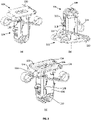
- FIG. 1 illustrates a typical clip 10 used for the attachment of airbags, such as, side-impact or curtain airbags, that is of the type formed by a body from which extend flexible elements 12 typically bearing against the surface of the clip entered into the attachment panel of the vehicle.
- the clip 10 comprises laterally protruding tangs 14 having upper surfaces 16 configured to bear against an inner surface of the attachment panel so as to "sandwich" the panel surface between the flexible elements 12 and the upper surfaces 16 of the tangs 14.
- Clip 10 may be formed from a single folded and punched laminar surface, so as to form a three-dimensional body made from, for example, metal, such as, carbon steel.
- clip 10 is designed in such a way that the top region (or head portion) does not provide sufficient area for the installer to safely and efficiently push the clip into the attachment panel. There are also exposed sharp edges on this top region which can lead to an uncomfortable insertion of the clip, or even potentially injure the installer during such insertion, i.e. when pushing the clip into an attachment panel opening.
- Fastening clip 20 comprises laterally protruding tangs 22 adapted to fixingly engage with the panel's inner surface when entered through a mounting aperture of the panel.
- Clip 20 is designed so as to either provide an unloaded connection, where the tangs 22 simply prevent the clip 20 from sliding out of the mounting aperture once installed, or where the connection is loaded only if the dimensions of the panel surface (thickness) and aperture (rectangular cut-out) are suitably matched to the clip design.
- the bias or spring load may be provided by a different component of the airbag module. Usually, this different component is made in plastic which, for a spring effect under mechanical loads (strength, fatigue) may not perform as good as metal.
- clip 20 has a flat upper surface, sharp edges are exposed at the upper surface making it uncomfortable and even risk injuries to the installer when pushing the fastening clip 20 into the mounting aperture.
- an object of the present invention to provide an improved and ergonomic fastening clip, suitable for attaching airbags, such as side-impact or curtain airbags, that robust and efficient, as well as, ergonomic and safe so as to minimise any potential risk to the user during assembly.
- a fastening clip for mounting a component part, such as an airbag, to a support structure comprising:
- the fastening clip of the present invention provides the advantage of an ergonomic pushing surface without any exposed sharp edges that may damage other components in the application or the user during assembly. Further, the fastening clip of the present invention provides the advantage of combining spring arms with an ergonomic pushing surface adapted, so as to prevent exposure of any sharp edges to the user or other components while the construction still allows the use of a single (uniaxial) folded (and punched) laminar sheet material (e.g. metal).
- a single (uniaxial) folded (and punched) laminar sheet material e.g. metal
- said plate member may be configured for push engagement by a digit of a user.
- each one of the two opposing resilient spring members may be uniaxially folded about a respective first and second folding axis.
- said first and second folding axis are perpendicular to said longitudinal axis. Even more preferably, said first and second folding axis are parallel to each other.
- said plate member may further comprise a first fold extending from at least a centre portion of said first edge and folded towards said body portion.
- said first fold may form a single fold about a first folding axis perpendicular to said longitudinal axis.
- said plate member may further comprise a second fold extending from at least a centre portion of said second edge and folded towards said lower end region of said body portion.
- said second fold may form a single fold about a second folding axis perpendicular to said longitudinal axis.
- said second folding axis may be parallel to said first folding axis.
- said plate member may further comprise at least one edge member extending from at least a central portion of each one of said first and second edges and folded towards said lower end region and said body portion.
- said at least one edge member may extend from each one of said opposing first and second edges into forming said body portion.
- At least one of said resilient spring members may be a flexion leg ending in a looped or folded end portion shaped, so as to minimise damage to the support structure and/or the user during assembly.
- said resilient spring members may be provided at diagonally opposing corners of said plate member.
- said body portion and said head portion may be formed from a single piece.
- a planar sheet material for forming a fastener clip comprising a predetermined pattern of cut-outs, fold lines and apertures, configured to fold into a fastener clip according to the first aspect of the present invention.
- said predetermined pattern of cut-outs, fold lines and apertures may be fabricated by any one of punching, stamping, cutting and bending.
- the described example embodiment relates to a fastening clip suitable for securing paraphernalia and accessories.
- the embodiment(s) of the invention are normally applied in vehicles. Although the invention is described with respect to vehicles, the invention is not restricted to vehicles altogether, but may also be used in other structures requiring attachment of accessories or peripheral components to a structure.
- the terms 'connected', 'attached', 'coupled', 'mounted' are intended to include direct connections between two members without any other members interposed therebetween, as well as, indirect connections between members in which one or more other members are interposed therebetween.
- the terminology includes the words specifically mentioned above, derivatives thereof, and words of similar import.
- the clip 100 of the present invention comprises an improved airbag clip of the type of clips which are used for the attachment of airbags, such as, for example side-impact or curtain airbags, the air bag clips are of the type formed by a pre-cut 2D blank (patterned and cut for folding).
- the clip 100 has a head portion 102 from which extend flexible elements, such as spring elements 114, that, during use, are adapted to bear against an outer surface of an attachment panel 500 when the clip 100 enters an aperture 502 of the panel 500, and a body 104, comprising descending tangs 110 which give rise to different structures for the clip 100, such as, for example, side limbs 112 having surfaces configured to bear against an inner surface of the panel 500 in such a way that the supporting surfaces and those provided by the flexible spring elements 114 engage the attachment panel 500 on both sides, i.e. in the form of a sandwich, thus, enabling the clip 100 to be fixedly supported on the attachment panel 500.
- flexible elements such as spring elements 114
- the improvements of the clip 100 comprise a pushing surface with an improved ergonomic shape, as well as, a head portion configured to protect from potential injuries during assembly. Furthermore, the improved airbag clip 100 has been simplified to include spring elements 114 extending directly from the head portion 102 and formed by a single fold of the spring elements 114 toward the distal end of the body 104
- Clips 100 for airbags such as those according to this invention are inserted into an opening made in the surface of the attachment panel 500.
- This surface effectively divides the clip 100 into an upper outer part, i.e. the head portion 102, which is not inserted into the opening and an inner lower part, i.e. the body portion 104, which is inserted into the opening (see Figures 5 and 6 ).
- the upper part or head portion 102 of the clip 100 corresponds to the outer part and the lower part or body portion 104 of the clip 100 corresponds to the inner part.
- the ascending direction is from the inner part to the outer (lower to upper) and the descending part is from the outer part to the inner (upper to lower).
- the body portion 104 may be formed by a box 106 that is formed by the union of two surfaces which are approximately "U"-shaped in transverse cross-section, being attached by one of their ends, and the attachment being strengthened by respective tabs 108 produced by division of the portions of the connecting part forming opposite surfaces.
- tabs 108 which are located within box 106 may have nails (not shown) that are shaped so as to engage in the openings provide in box 106.
- Tangs 110 have an inclination towards the central axis 128 of the clip and extend downwards from box 106 towards the centre of clip 100 to then form a loop and extend away from the centre of the clip 100 in the opposite direction as ascending side limbs 112.
- the loops of tangs 110 may be in contact with each other. This contact provides strength to the clip against pull-out forces.
- Tangs 110 may have an enlarged surface 116, almost in the form of a triangle, which allows its base to extend beyond the walls forming box 106. This obviously prevents box 106 from “descending” under pressure and passing beyond those stops represented by the enlarged surface 116.
- Side limbs 112 are configured to emerge from the inner part of box 106 towards the exterior of the same, through a hollow space, opening or window 118 made in its surface, creating a bearing surface 132 that is approximately parallel to the flat upper surface of the head portion 102 and which is configured to engage with the panel 500 (whin in use).
- the sides of window 118 may have lateral tabs 120 which provide a support for the bearing surfaces 132 of box 106 against the inner surface of the panel 500 in response to forces which tend to extract clip 100.
- the upper part or head portion 102 of the clip 100 comprises a substantially rectangularly shaped plate 122 with a flat upper surface.
- the plate 122 is arranged transverse to a longitudinal axis 128 of the body portion 104.
- Resilient spring elements 114 i.e. flexion leg
- Each spring element 114 is folded towards the body portion 104, so as to form an obtuse angle with the flat upper surface of the plate 122.
- Respective folds are uniaxial about a single axis 130 that is perpendicular to the longitudinal axis 128 of the clip 100.
- the fold of the spring elements 114 forms a rounded side edge 134 of the plate 122.
- a distal end portion of each spring element 114 is looped back, so as to form a rounded spring element end (i.e. a tear-drop hem).
- a central portion 124 of two opposing protruding side edges of the plate 122 is folded towards and merging into a respective side of the body portion 104 (i.e. forming the box 106), so as to form a rounded side edge (e.g. a closed or open hem).
- the plate 122 may be provided with two centrally aligned apertures 126, so as to allow access to the inner part of box 106.
- the clip 100 may be formed from a single laminar surface 200 (i.e. a sheet material or blank) that is cut and punched in a unique way, so as to allow forming a three-dimensional embodiment of the clip 100 by simply folding respective cut or punched portions of the sheet material 200 at predetermined fold lines.
- the laminar surface i.e. sheet material or blank
- the laminar surface may be a sheet metal blank 200 comprising predetermined cuts, bends and apertures that when folded form the specific parts and portions of the three-dimensional clip 100.
- Figure 7 includes the reference signs pointing to the 2D portion of the parts of the clip 100 once formed.
- the sheet metal material may be cut, punched, stamped or bent utilising suitable tooling (e.g. press, drills, laser cutting etc.).
- the unique cut-out pattern of the sheet metal allows for a clip with two spring elements 114 extending directly from the plate 122 of the head portion 102 and uniaxially bent about a single axis 130 that is perpendicular to the longitudinal centre axis 128 of the clip 100, thus, minimising the material required to form the intended shape (and functionality) of the clip 100.
- the laminar surface or sheet metal blank may be made from a metal, such as, for example, carbon steel which has been heat treated to impart improved strength qualities to it. Further, clip 100 may undergo treatment to prevent corrosion and/or receive a suitable coating in order to improve its service life and wear in relation to dust, moisture and other elements which might attack the clip.
- the user simply pushes the fastening clip 100 into the mounting aperture 502 of the attachment panel 500 thus fixingly engaging the side limbs 112 with an inner surface of the attachment panel 500.
- the flat surface and round edges of the plate 122 provide an ergonomic pushing surface adapted to minimise potential injuries to the user during assembly.
Landscapes
- Engineering & Computer Science (AREA)
- General Engineering & Computer Science (AREA)
- Mechanical Engineering (AREA)
- Clamps And Clips (AREA)
- Insertion Pins And Rivets (AREA)
- Connection Of Plates (AREA)
Priority Applications (2)
| Application Number | Priority Date | Filing Date | Title |
|---|---|---|---|
| CN202210021099.8A CN114802083A (zh) | 2021-01-18 | 2022-01-10 | 改进的人体工程学紧固夹 |
| US17/574,995 US20220228611A1 (en) | 2021-01-18 | 2022-01-13 | Ergonomic fastening clip |
Applications Claiming Priority (1)
| Application Number | Priority Date | Filing Date | Title |
|---|---|---|---|
| ES202130026 | 2021-01-18 |
Publications (2)
| Publication Number | Publication Date |
|---|---|
| EP4047221A1 true EP4047221A1 (de) | 2022-08-24 |
| EP4047221A8 EP4047221A8 (de) | 2024-06-26 |
Family
ID=82486488
Family Applications (1)
| Application Number | Title | Priority Date | Filing Date |
|---|---|---|---|
| EP21201530.9A Pending EP4047221A1 (de) | 2021-01-18 | 2021-10-07 | Verbesserte ergonomische befestigungsklammer |
Country Status (3)
| Country | Link |
|---|---|
| US (1) | US20220228611A1 (de) |
| EP (1) | EP4047221A1 (de) |
| CN (1) | CN114802083A (de) |
Families Citing this family (1)
| Publication number | Priority date | Publication date | Assignee | Title |
|---|---|---|---|---|
| EP4328458A1 (de) * | 2022-08-22 | 2024-02-28 | Illinois Tool Works Inc. | Verbesserte befestigungsklammer |
Citations (5)
| Publication number | Priority date | Publication date | Assignee | Title |
|---|---|---|---|---|
| US20130302087A1 (en) * | 2011-02-02 | 2013-11-14 | A. Raymond Et Cie | Fastening device |
| WO2018104421A1 (de) * | 2016-12-09 | 2018-06-14 | A.RAYMOND et Cie. SCS | Clip zum befestigen eines ersten elements an einem zweiten element |
| US20180209454A1 (en) * | 2015-07-24 | 2018-07-26 | A. Raymond Et Cie | Device for holding a component |
| US20200166061A1 (en) * | 2017-05-29 | 2020-05-28 | A. Raymond Et Cie | Clip for fastening a first element to a second element and device with a clip of this kind |
| EP3748169A1 (de) * | 2019-06-06 | 2020-12-09 | Illinois Tool Works Inc. | Ergonomische befestigungsklammer |
Family Cites Families (6)
| Publication number | Priority date | Publication date | Assignee | Title |
|---|---|---|---|---|
| US8474111B2 (en) * | 2008-11-17 | 2013-07-02 | Itw Metal Fasteners, S.L. | Panel-fastening clips, especially for curtain or lateral airbags |
| JP5480304B2 (ja) * | 2009-03-06 | 2014-04-23 | イリノイ トゥール ワークス インコーポレイティド | アクセサリーを車両パネルに固定するためのクリップの改良 |
| CN104136786B (zh) * | 2012-03-02 | 2017-07-21 | 伊利诺斯工具制品有限公司 | 气囊锚固夹组件 |
| FR3020098B1 (fr) * | 2014-04-22 | 2017-05-05 | A Raymond Et Cie | Dispositif de fixation par cramponnage |
| DE102015117007B3 (de) * | 2015-10-06 | 2017-03-30 | Bjb Gmbh & Co. Kg | Befestigungselement |
| EP3754207B1 (de) * | 2019-06-17 | 2022-08-03 | Illinois Tool Works Inc. | Befestigungsclip |
-
2021
- 2021-10-07 EP EP21201530.9A patent/EP4047221A1/de active Pending
-
2022
- 2022-01-10 CN CN202210021099.8A patent/CN114802083A/zh active Pending
- 2022-01-13 US US17/574,995 patent/US20220228611A1/en not_active Abandoned
Patent Citations (5)
| Publication number | Priority date | Publication date | Assignee | Title |
|---|---|---|---|---|
| US20130302087A1 (en) * | 2011-02-02 | 2013-11-14 | A. Raymond Et Cie | Fastening device |
| US20180209454A1 (en) * | 2015-07-24 | 2018-07-26 | A. Raymond Et Cie | Device for holding a component |
| WO2018104421A1 (de) * | 2016-12-09 | 2018-06-14 | A.RAYMOND et Cie. SCS | Clip zum befestigen eines ersten elements an einem zweiten element |
| US20200166061A1 (en) * | 2017-05-29 | 2020-05-28 | A. Raymond Et Cie | Clip for fastening a first element to a second element and device with a clip of this kind |
| EP3748169A1 (de) * | 2019-06-06 | 2020-12-09 | Illinois Tool Works Inc. | Ergonomische befestigungsklammer |
Also Published As
| Publication number | Publication date |
|---|---|
| EP4047221A8 (de) | 2024-06-26 |
| CN114802083A (zh) | 2022-07-29 |
| US20220228611A1 (en) | 2022-07-21 |
Similar Documents
| Publication | Publication Date | Title |
|---|---|---|
| EP4328458A1 (de) | Verbesserte befestigungsklammer | |
| EP3748169A1 (de) | Ergonomische befestigungsklammer | |
| US7530599B2 (en) | Flexible housing for an airbag module | |
| JP3214247B2 (ja) | ドアトリムのエネルギ吸収構造 | |
| EP1899199B1 (de) | Flexibles gehäuse für ein airbag-modul | |
| JP4870488B2 (ja) | 高固定強度の固定具 | |
| US7780187B2 (en) | Mounting structure for curtain airbag | |
| US6049952A (en) | Energy absorbing trim component fastening system | |
| EP0922614A1 (de) | Kraftfahrzeug und Kraftfahrzeug-Luftsackmodul | |
| JP2013141944A (ja) | 自動車用ドアトリムの取付構造 | |
| US6877766B2 (en) | Holder for vehicle upholstery | |
| EP4047221A1 (de) | Verbesserte ergonomische befestigungsklammer | |
| JP4383868B2 (ja) | エアバッグのz高制御タブ | |
| EP0855313A1 (de) | Energieabsorbierende Struktur für eine Kraftfahrzeugkarosserie | |
| EP1621416A2 (de) | Airbageinheit und Gehäuse dafür | |
| KR100204185B1 (ko) | 자동차 안전 장치 | |
| EP3822497B1 (de) | Befestigungsklammeranordnung | |
| EP4253769A1 (de) | Befestigungsklammeranordnung | |
| JPH0620164U (ja) | 衝撃吸収ステアリング装置 | |
| EP1125068B1 (de) | Blattfedereinrichtung für kraftfahrzeug | |
| CN215284516U (zh) | 辅助扶手支架 | |
| CN116085363A (zh) | 一种弹性紧固装置 | |
| US20030111827A1 (en) | Airbag housing | |
| JP2009056891A (ja) | エアバッグ固着構造及び前記固着構造を用いたエアバッグモジュール | |
| CN117922483A (zh) | 侧气帘支架以及侧气帘装置 |
Legal Events
| Date | Code | Title | Description |
|---|---|---|---|
| PUAI | Public reference made under article 153(3) epc to a published international application that has entered the european phase |
Free format text: ORIGINAL CODE: 0009012 |
|
| STAA | Information on the status of an ep patent application or granted ep patent |
Free format text: STATUS: THE APPLICATION HAS BEEN PUBLISHED |
|
| AK | Designated contracting states |
Kind code of ref document: A1 Designated state(s): AL AT BE BG CH CY CZ DE DK EE ES FI FR GB GR HR HU IE IS IT LI LT LU LV MC MK MT NL NO PL PT RO RS SE SI SK SM TR |
|
| STAA | Information on the status of an ep patent application or granted ep patent |
Free format text: STATUS: REQUEST FOR EXAMINATION WAS MADE |
|
| 17P | Request for examination filed |
Effective date: 20230222 |
|
| RBV | Designated contracting states (corrected) |
Designated state(s): AL AT BE BG CH CY CZ DE DK EE ES FI FR GB GR HR HU IE IS IT LI LT LU LV MC MK MT NL NO PL PT RO RS SE SI SK SM TR |
|
| RIC1 | Information provided on ipc code assigned before grant |
Ipc: F16B 21/08 20060101ALI20240416BHEP Ipc: B60R 21/20 20110101ALI20240416BHEP Ipc: F16B 2/24 20060101AFI20240416BHEP |
|
| GRAP | Despatch of communication of intention to grant a patent |
Free format text: ORIGINAL CODE: EPIDOSNIGR1 |
|
| STAA | Information on the status of an ep patent application or granted ep patent |
Free format text: STATUS: GRANT OF PATENT IS INTENDED |
|
| INTG | Intention to grant announced |
Effective date: 20240610 |
|
| P01 | Opt-out of the competence of the unified patent court (upc) registered |
Free format text: CASE NUMBER: APP_41708/2024 Effective date: 20240715 |
|
| GRAS | Grant fee paid |
Free format text: ORIGINAL CODE: EPIDOSNIGR3 |