EP4047191B1 - Instrumentierter turbinenabgaskanal - Google Patents
Instrumentierter turbinenabgaskanal Download PDFInfo
- Publication number
- EP4047191B1 EP4047191B1 EP22156448.7A EP22156448A EP4047191B1 EP 4047191 B1 EP4047191 B1 EP 4047191B1 EP 22156448 A EP22156448 A EP 22156448A EP 4047191 B1 EP4047191 B1 EP 4047191B1
- Authority
- EP
- European Patent Office
- Prior art keywords
- exhaust duct
- probes
- egt
- turbine
- engine
- Prior art date
- Legal status (The legal status is an assumption and is not a legal conclusion. Google has not performed a legal analysis and makes no representation as to the accuracy of the status listed.)
- Active
Links
Images

Classifications
-
- F—MECHANICAL ENGINEERING; LIGHTING; HEATING; WEAPONS; BLASTING
- F01—MACHINES OR ENGINES IN GENERAL; ENGINE PLANTS IN GENERAL; STEAM ENGINES
- F01N—GAS-FLOW SILENCERS OR EXHAUST APPARATUS FOR MACHINES OR ENGINES IN GENERAL; GAS-FLOW SILENCERS OR EXHAUST APPARATUS FOR INTERNAL-COMBUSTION ENGINES
- F01N13/00—Exhaust or silencing apparatus characterised by constructional features
- F01N13/008—Mounting or arrangement of exhaust sensors in or on exhaust apparatus
-
- F—MECHANICAL ENGINEERING; LIGHTING; HEATING; WEAPONS; BLASTING
- F01—MACHINES OR ENGINES IN GENERAL; ENGINE PLANTS IN GENERAL; STEAM ENGINES
- F01D—NON-POSITIVE DISPLACEMENT MACHINES OR ENGINES, e.g. STEAM TURBINES
- F01D17/00—Regulating or controlling by varying flow
- F01D17/02—Arrangement of sensing elements
- F01D17/08—Arrangement of sensing elements responsive to condition of working-fluid, e.g. pressure
- F01D17/085—Arrangement of sensing elements responsive to condition of working-fluid, e.g. pressure to temperature
-
- F—MECHANICAL ENGINEERING; LIGHTING; HEATING; WEAPONS; BLASTING
- F01—MACHINES OR ENGINES IN GENERAL; ENGINE PLANTS IN GENERAL; STEAM ENGINES
- F01D—NON-POSITIVE DISPLACEMENT MACHINES OR ENGINES, e.g. STEAM TURBINES
- F01D21/00—Shutting-down of machines or engines, e.g. in emergency; Regulating, controlling, or safety means not otherwise provided for
- F01D21/003—Arrangements for testing or measuring
-
- F—MECHANICAL ENGINEERING; LIGHTING; HEATING; WEAPONS; BLASTING
- F01—MACHINES OR ENGINES IN GENERAL; ENGINE PLANTS IN GENERAL; STEAM ENGINES
- F01D—NON-POSITIVE DISPLACEMENT MACHINES OR ENGINES, e.g. STEAM TURBINES
- F01D25/00—Component parts, details, or accessories, not provided for in, or of interest apart from, other groups
- F01D25/30—Exhaust heads, chambers, or the like
-
- F—MECHANICAL ENGINEERING; LIGHTING; HEATING; WEAPONS; BLASTING
- F02—COMBUSTION ENGINES; HOT-GAS OR COMBUSTION-PRODUCT ENGINE PLANTS
- F02K—JET-PROPULSION PLANTS
- F02K1/00—Plants characterised by the form or arrangement of the jet pipe or nozzle; Jet pipes or nozzles peculiar thereto
- F02K1/78—Other construction of jet pipes
-
- F—MECHANICAL ENGINEERING; LIGHTING; HEATING; WEAPONS; BLASTING
- F05—INDEXING SCHEMES RELATING TO ENGINES OR PUMPS IN VARIOUS SUBCLASSES OF CLASSES F01-F04
- F05D—INDEXING SCHEME FOR ASPECTS RELATING TO NON-POSITIVE-DISPLACEMENT MACHINES OR ENGINES, GAS-TURBINES OR JET-PROPULSION PLANTS
- F05D2220/00—Application
- F05D2220/30—Application in turbines
- F05D2220/32—Application in turbines in gas turbines
- F05D2220/323—Application in turbines in gas turbines for aircraft propulsion, e.g. jet engines
Definitions
- the application relates generally to gas turbine engines and, more particularly, to an instrumented turbine exhaust duct.
- Exhaust gas temperature (EGT) probes are used to measure the temperature of turbine exhaust gases. As these probes are used in a harsh environment, they need to be properly protected and periodically inspected/replaced to ensure accurate EGT readings. However, with some engine architectures, access to the probes can be challenging and/or the probes may be exposed to adverse elements, which may negatively affect their durability.
- EP 3 453 841 A1 discloses a prior art gas turbine engine as set forth in the preamble of claim 1.
- EP 3 043 056 A2 discloses a prior art exhaust duct for a gas turbine engine.
- US 4 580 910 A discloses a prior art engine exhaust gas test harness.
- Fig. 1 illustrates an aircraft power plant comprising a nacelle N housing a gas turbine engine 10 of a type preferably provided for use in subsonic flight, generally comprising in serial flow communication an air inlet 11, a compressor section 12 for pressurizing the air from the air inlet 11, a combustor 13 in which the compressed air is mixed with fuel and ignited for generating an annular stream of hot combustion gases, a turbine section 14 for extracting energy from the combustion gases, an exhaust system 15 through which the combustion gases exit the engine 10.
- the engine 10 has a longitudinal center axis 17.
- the engine 10 in Fig. 1 is a turboprop engine 10 and includes a propeller 16, which provides thrust for flight and taxiing.
- the propeller 16 includes a nose cone 16A and propeller blades 16B, which rotate about the center axis 17 to provide thrust. It is understood that the engine 10 can adopt various other configurations. For instance, the engine could be configured as a turboshaft engine having an output shaft connectable to a rotatable load, such as a helicopter rotor or the like.
- the engine 10 has an outer case 18 housing a central core through which gases flow and which includes most of the turbomachinery of the engine 10.
- the illustrated engine 10 is a "reverse-flow” engine 10 because gases flow through the core from the air inlet 11 at a rear or aft portion of the engine 10, to the exhaust system 15 at a front portion of the engine 10. This is in contrast to "through-flow” gas turbine engines in which gases flow through the core of the engine from a front portion to a rear portion.
- the direction of the flow of gases through the engine 10 is shown in Fig. 1 with arrows F.
- forward and “aft” used herein may refer to the relative disposition of components of the engine 10, in correspondence to the “forward” and “aft” directions of the engine 10 and aircraft including the engine 10 as defined with respect to the direction of travel D.
- a component of the engine 10 that is “forward” of another component is arranged within the engine 10 such that it is located closer to the propeller 16.
- a component of the engine 10 that is “aft” of another component is arranged within the engine 10 such that it is further away from the propeller 16.
- the core of the engine 10 may include one or more spools.
- the illustrated embodiment is a two-spool engine including a low pressure (LP) spool and a high pressure (HP) spool rotatable about the center axis 17 to perform compression to pressurize the air received through the air inlet 11, and to extract energy from the combustion gases before they exit the core via the exhaust system 15 at a forward end of the core.
- the core may include other components as well, including, but not limited to internal combustion engines (e.g. rotary engines such as Wankel engines for compounding power with a turbine of the turbine section), gearboxes, tower shafts, and bleed air outlets.
- Each spool generally includes at least one component to compress the air that is part of the compressor section 12, and at least one component to extract energy from the combustion gases that is part of the turbine section 14. More particularly, according to the illustrated embodiment, the LP spool has an LP turbine 14a which extracts energy from the combustion gases, and an LP compressor 12a for pressurizing the air.
- the LP turbine 14a and the LP compressor 12a can each include one or more stages of rotors and stators, depending upon the desired engine thermodynamic cycle, for example.
- the LP spool further comprises an LP shaft 22 drivingly connecting the LP turbine 12a to the LP compressor 14a. Gears (not shown) can be provided to allow the LP compressor 14a to rotate at a different speed than the LP turbine 12a.
- the LP turbine 12a is also drivingly connected to the propeller 16 via a reduction gear box (RGB) 20.
- RGB 20 allows for the propeller 16 to be driven at its optimal rotational speed, which is different from the rotational speed of the
- the HP spool comprises an HP turbine 14b drivingly engaged (e.g. directly connected) to a HP compressor 12b by a high pressure shaft 24.
- the HP turbine 14b and the HP compressor 12b can each include one or more stages of rotors and stators.
- the LP compressor 12a, the HP compressor 12b, the combustor 13, the HP turbine 14b and the LP turbine 14a are in serial flow communication via an annular gas path 26 extending through the core about the center axis 17.
- the gas path 26 leads to the engine exhaust system 15 downstream of the turbine section 14.
- the exhaust system 15 of the engine 10 comprises a turbine exhaust duct 30 for exhausting combustion gases received from the last stage of the LP turbine 14a.
- the exhaust duct 30 is a non-axisymmetric dual port exhaust duct configured for directing combustion gases laterally on opposed sides of the outer case 18 of the engine 10 of the aircraft power plant.
- the dual port exhaust duct 30 is qualified as "non-axisymmetric" because the two exhaust ports thereof are not coaxial to the center axis 17 of the engine (i.e. the exhaust flow discharged from the exhaust duct is not axial, it is rather directed in a direction that diverges from the center axis 17).
- the dual port exhaust duct 30 has a generally "Y-shaped" body including an annular central inlet conduit portion 30a extending axially around the center axis 17 for receiving the annular flow of combustions gases discharged from the last stage of LP turbine 14a, and first and second diverging outlet conduit portions 30b, 30c branching off laterally from the central inlet conduit portion 30a.
- the first and second outlet conduit portions 30b, 30c are identical.
- each outlet conduit portion 30b, 30c projects outwardly of the engine outer case 18 into an air space or gap G between the outer case 18 and the nacelle N.
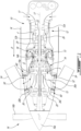
- each outlet conduit portion 30b, 30c terminates into an exhaust port including an annular outer flange 40 surrounding a central exhaust port opening 42.
- the central exhaust port has a central axis A which is oriented to intersect the center axis 17.
- the axis A has a main radial component and a secondary (i.e. smaller) axial component relative to the center axis 17.
- the exhaust port is oriented to direct the combustion gases mainly in a radially outward direction.
- the exhaust port opening 42 and surrounding annular flange 40 are circular. However, it is understood that other geometries are contemplated as well (e.g. oval).
- first and second tailpipes TP are respectively detachably mounted to the annular flange 40 of the first and second outlet conduit portions 30b, 30c.
- the tailpipes TP can be provided with an annular flange complementary to the annular flange 40 of the exhaust duct 30.
- the tailpipes TP extend outwardly from the nacelle N and curve towards a rearward direction to discharge the combustion gases received from the exhaust duct 30 into the surrounding environment on opposed sides of the nacelle N and with a generally rearward component.
- the temperature of the exhaust gases may be used to measure the performance of the engine 10 and to provide an indication of the rate of deterioration of gas turbine engine components.
- the exhaust gas temperature (EGT) is an indicator of engine status, which may be used to measure and control operational and functional characteristics of the engine 10.
- the EGT measurement system comprises first and second sets of operatively interconnected EGT probes 50, 52.
- the EGT probes 50, 52 are positioned outside the outer case 18 of the engine 10 in the air space/gap G between the nacelle N and the outer case 18. More particularly, the first set of EGT probes 50 is provided at the exhaust port of the first outlet conduit portion 30b, and the second set of EGT probes 52 is provided at the exhaust port of the second outlet conduit portion 30c.
- the EGT probes 50, 52 may be distributed in predetermined positions around the exhaust port of each outlet conduit portion 30b, 30c of the exhaust duct 30 and inserted to a predetermined depth into the duct to establish the temperature of the combustion gases as they exit the exhaust duct 30.
- six probes are uniformly circumferentially distributed around the exhaust port of each outlet conduit portion 30b, 30c.
- the exhaust gas temperature profile for a particular engine may be determined by using a plurality of probes or thermocouple elements so arranged around each exhaust port at various penetration depths.
- each shield 60 has a cap-shaped body including a cylindrical skirt 60a extending from an outer periphery of end wall forming an annular inward flange 60b around a central opening 60c.
- the flange 60b is complementary to the annular flange 40 at the end of each outlet conduit portion 30b, 30c of the exhaust duct 30 and is adapted to be detachably connected thereto such as by bolting or the like. According to the embodiment shown in Fig.
- the flange 60b of the shields 60 are sandwiched between the flanges of the exhaust duct 30 and the tailpipes TP. That is the shields 60 are mounted at the interface between the exhaust duct 30 and the tailpipes TP.
- access to the probes 50, 52 can be readily provided by opening the nacelle N, detaching the tailpipes TP from the dual port exhaust duct 30 and then removing the shields 60 from the exhaust ports of the exhaust duct 30.
- the shields 60 can be bolted back to the exhaust ends of the exhaust duct 30 in order to protect the probes 50, 52. As best shown in Fig.
- each shield 60 surrounds the associated probes 50, 52 all around each exhaust end of the exhaust duct 30.
- the central opening 60c of the shield 60 may be sized to be slightly larger than the exhaust port opening 42 so as to not interfere with the flow of exhaust gases.
- the central opening 60c of the shield is centered relative to axis A once the shield 60 has been properly secured to the flange 40 at each exhaust end of the exhaust duct 30.
- the skirt 60a is configured to form an annulus around each exhaust end of the exhaust duct 30. The head of the probes 50, 52 and the wiring harness are accommodated in this annulus.
- the shields 60 thus form a physical barrier to protect the probes 50, 52 and associated wiring in the air space/gap G from tool, parts or fluid surrounding the engine outer case 18.
- the shields 60 provide thermal shielding to the probes 50, 52.
- the shields 60 contribute to improve the EGT probes 50, 52 functionality and durability by decreasing the risk of probes or wire damages.
- each shield 60 has a unitary body made from Inconel 625 or other suitable sheet metal material pressed or stamped into an inverted cup-shaped body.
Landscapes
- Engineering & Computer Science (AREA)
- Mechanical Engineering (AREA)
- General Engineering & Computer Science (AREA)
- Chemical & Material Sciences (AREA)
- Combustion & Propulsion (AREA)
- Analytical Chemistry (AREA)
- Exhaust Silencers (AREA)
Claims (10)
- Gasturbinentriebwerk (10), umfassend:ein Außengehäuse (18);einen Kern innerhalb des Außengehäuses (18), wobei der Kern beinhaltet:eine Brennkammer (13),mindestens eine Spule, die zur Drehung um eine Mittelachse (17) montiert ist, wobei die mindestens eine Spule einen Kompressor (12) und eine Turbine (14) beinhaltet,einen ringförmigen Gaspfad (26), der sich zwischen dem Kompressor (12) und der Turbine (14) um die Mittelachse (17) erstreckt; undeinen Turbinenabgaskanal (30), der sich von dem ringförmigen Gaspfad (26) stromabwärts der Turbine (14) in einer Richtung weg von der Mittelachse (17) erstreckt, wobei der Turbinenabgaskanal (30) einen stromabwärtigen Endabschnitt (30b; 30c) aufweist, der von dem Außengehäuse (18) nach außen vorsteht, wobei der stromabwärtige Endabschnitt (30b; 30c) mit Sonden für Abgastemperatur (exhaust gas temperature - EGT) (50; 52) instrumentiert ist,dadurch gekennzeichnet, dass:die EGT-Sonden (50; 52) durch einen Kabelbaum außerhalb des Turbinenabgaskanals (30) elektrisch miteinander verbunden sind und um den stromabwärtigen Endabschnitt (30b; 30c) des Turbinenabgaskanals (30) außerhalb des Außengehäuses (18) des Gasturbinentriebwerks (10) verteilt sind; undder stromabwärtige Endabschnitt (30b; 30c) des Turbinenabgaskanals (30) eine Abgasanschlussöffnung (42) definiert, die durch einen ringförmigen Flansch (40) umgeben ist, und wobei eine Abschirmung (60) abnehmbar an dem ringförmigen Flansch (40) montiert ist, wobei die Abschirmung (60) eine ringförmige Schürze (60a) aufweist, welche die EGT-Sonden (50; 52) um den stromabwärtigen Endabschnitt (30b; 30c) des Turbinenabgaskanals (30) umgibt, wobei die ringförmige Schürze (60a) einen Ringraum um den stromabwärtigen Endabschnitt (30b; 30c) des Turbinenabgaskanals (30) bildet, wobei der Kabelbaum in dem Ringraum aufgenommen ist.
- Gasturbinentriebwerk (10) nach Anspruch 1, wobei die Abgasanschlussöffnung (42) eine Abgasachse (A) aufweist, welche die Mittelachse (17) schneidet.
- Gasturbinentriebwerk (10) nach Anspruch 1 oder 2, wobei der Turbinenabgaskanal (30) ein Abgaskanal (30) mit zwei Anschlüssen ist, der einen Y-förmigen Körper aufweist, der einen ersten und einen zweiten Auslassleitungsabschnitt (30b, 30c) beinhaltet, die von einer zentralen ringförmigen Einlassleitung (30a) abzweigen, die koaxial zu der Mittelachse (17) ist.
- Gasturbinentriebwerk (10) nach Anspruch 3, wobei die EGT-Sonden (50; 52) einen ersten Satz von EGT-Sonden (50), die elektrisch miteinander verbunden und um einen ersten Abgasanschluss des ersten Auslassleitungsabschnitts (30b) verteilt sind, und einen zweiten Satz von EGT-Sonden (52) beinhalten, die elektrisch miteinander verbunden und um einen zweiten Abgasanschluss des zweiten Auslassleitungsabschnitts (30c) verteilt sind, und wobei eine erste und eine zweite Abschirmung (60) jeweils an dem ersten und dem zweiten Auslassleitungsabschnitt (30b, 30c) montiert sind, wobei die erste Abschirmung (60) den ersten Satz von EGT-Sonden (50) umgibt und die zweite Abschirmung (60) den zweiten Satz von EGT-Sonden (52) umgibt.
- Gasturbinentriebwerk (10) nach einem der Ansprüche 1 bis 4, wobei die Abschirmung (60) einen kappenförmigen Körper aufweist, der eine Endwand (60b) beinhaltet, wobei die ringförmige Schürze (60a) von einem Umfang der Endwand (60b) herabhängt, wobei die Endwand (60b) eine zentrale Öffnung (60c) definiert, die mit der Abgasanschlussöffnung (42) des Turbinenabgaskanals (30) ausgerichtet ist, wobei die EGT-Sonden (50; 52) in den Ringraum hineinragen.
- Gasturbinentriebwerk (10) nach Anspruch 5, wobei die Endwand (60b) mit dem ringförmigen Flansch (40) des Turbinenabgaskanals (30) verschraubt ist.
- Gasturbinentriebwerk (10) nach einem der vorhergehenden Ansprüche, wobei das Gasturbinentriebwerk (10) ein Gasturbinentriebwerk (10) mit Umkehrströmung ist, bei dem die Verbrennungsgase in einer Vorwärtsrichtung (D) von einem Lufteinlass (11) an einem hinteren Ende des Kerns zu dem Turbinenabgaskanal (30) an einem vorderen Ende des Kerns strömen.
- Luftfahrzeugkraftwerk, umfassend:eine Gondel (N); undein Gasturbinentriebwerk (10) nach einem der Ansprüche 1 bis 7, wobei das Außengehäuse (18) des Gasturbinentriebwerks (10) in der Gondel (N) montiert ist, das Außengehäuse (18) und die Gondel (N) einen Spalt (G) definieren, der Turbinenabgaskanal (30) sich in den Spalt (G) zwischen der Gondel (N) und dem Außengehäuse (18) erstreckt, die Sonden für Abgastemperatur (EGT) (50; 52) in dem Spalt (G) angeordnet sind und in den Turbinenabgaskanal (30) hineinragen; undein Auspuffrohr (TP), das sich von einem stromabwärtigen Ende des Turbinenabgaskanals (30) in den Spalt (G) erstreckt und aus der Gondel (N) nach außen vorsteht.
- Luftfahrzeugkraftwerk nach Anspruch 8, wobei die Abschirmung (60) an einer Schnittstelle zwischen dem Turbinenabgaskanal (30) und dem Auspuffrohr (TP) montiert ist.
- Luftfahrzeugkraftwerk nach Anspruch 8 oder 9, wobei das Auspuffrohr (TP) einen Ringflansch aufweist und die Abschirmung (60) einen Ringflansch (60b) aufweist, wobei der Ringflansch (60b) der Abschirmung (60) sandwichartig zwischen dem Ringflansch des Auspuffrohrs (TP) und dem Ringflansch (40) des Turbinenabgaskanals (30) liegt.
Applications Claiming Priority (1)
| Application Number | Priority Date | Filing Date | Title |
|---|---|---|---|
| US17/178,708 US11473480B2 (en) | 2021-02-18 | 2021-02-18 | Instrumented turbine exhaust duct |
Publications (2)
| Publication Number | Publication Date |
|---|---|
| EP4047191A1 EP4047191A1 (de) | 2022-08-24 |
| EP4047191B1 true EP4047191B1 (de) | 2024-09-04 |
Family
ID=80447355
Family Applications (1)
| Application Number | Title | Priority Date | Filing Date |
|---|---|---|---|
| EP22156448.7A Active EP4047191B1 (de) | 2021-02-18 | 2022-02-11 | Instrumentierter turbinenabgaskanal |
Country Status (3)
| Country | Link |
|---|---|
| US (1) | US11473480B2 (de) |
| EP (1) | EP4047191B1 (de) |
| CA (1) | CA3149084A1 (de) |
Families Citing this family (3)
| Publication number | Priority date | Publication date | Assignee | Title |
|---|---|---|---|---|
| US11630031B2 (en) * | 2021-06-29 | 2023-04-18 | Rolls-Royce North American Technologies Inc. | Engine-mounted instrumentation assembly |
| US11952962B1 (en) * | 2023-01-31 | 2024-04-09 | Pratt & Whitney Canada Corp. | Exhaust duct for gas turbine engine |
| US12246844B1 (en) * | 2023-11-29 | 2025-03-11 | Pratt & Whitney Canada Corp. | Hybrid aircraft power plant |
Family Cites Families (15)
| Publication number | Priority date | Publication date | Assignee | Title |
|---|---|---|---|---|
| US2979151A (en) * | 1956-06-21 | 1961-04-11 | Bristol Siddeley Engines Ltd | Silencers |
| US2877860A (en) * | 1956-07-23 | 1959-03-17 | Hoffar Henry Stonestreet | Apertured pliable resilient damper wall silencer |
| US2999388A (en) * | 1958-11-13 | 1961-09-12 | Western Electric Co | Electrical probe |
| US3520133A (en) * | 1968-03-14 | 1970-07-14 | Gen Electric | Gas turbine control system |
| US3990308A (en) * | 1973-11-23 | 1976-11-09 | Mccormick Robert Ian | Temperature measurement system for free turbine type gas turbine engines |
| US4580910A (en) * | 1985-01-24 | 1986-04-08 | National Flight Services, Inc. | Engine exhaust gas test harness |
| US5230214A (en) * | 1992-09-09 | 1993-07-27 | United Technologies Corporation | Recirculating zone inducing means for an augmentor burning section |
| US5404760A (en) * | 1993-10-27 | 1995-04-11 | Westinghouse Electric Corporation | Blade path thermocouple and exhaust gas extraction probe for combustion turbines |
| JP2002070584A (ja) * | 2000-08-30 | 2002-03-08 | Toshiba Corp | ガスタービンプラント |
| JP2006083730A (ja) * | 2004-09-15 | 2006-03-30 | Hitachi Ltd | ガスタービンの着火検出方法 |
| CN104995382B (zh) * | 2012-11-30 | 2018-02-23 | 凯斯纽荷兰(中国)管理有限公司 | 用于越野车的排气系统 |
| EP3550133B1 (de) * | 2014-12-17 | 2022-03-16 | Pratt & Whitney Canada Corp. | Abgaskanal für ein gasturbinentriebwerk |
| US9880059B2 (en) * | 2015-06-08 | 2018-01-30 | Siemens Energy, Inc. | Gas turbine exhaust diffuser mounted blade path thermocouple probe |
| US10808624B2 (en) * | 2017-02-09 | 2020-10-20 | Pratt & Whitney Canada Corp. | Turbine rotor with low over-speed requirements |
| US20190078459A1 (en) * | 2017-09-11 | 2019-03-14 | United Technologies Corporation | Active clearance control system for gas turbine engine with power turbine |
-
2021
- 2021-02-18 US US17/178,708 patent/US11473480B2/en active Active
-
2022
- 2022-02-11 EP EP22156448.7A patent/EP4047191B1/de active Active
- 2022-02-16 CA CA3149084A patent/CA3149084A1/en active Pending
Also Published As
| Publication number | Publication date |
|---|---|
| US20220260001A1 (en) | 2022-08-18 |
| EP4047191A1 (de) | 2022-08-24 |
| US11473480B2 (en) | 2022-10-18 |
| CA3149084A1 (en) | 2022-08-18 |
Similar Documents
| Publication | Publication Date | Title |
|---|---|---|
| EP4047191B1 (de) | Instrumentierter turbinenabgaskanal | |
| EP3580433B1 (de) | Drucksensoranordnung für einen turbinenmotor | |
| EP4067625B1 (de) | Gasturbinentriebwerk mit einer messsonde | |
| EP2935803B1 (de) | In eine gasturbinenschaufel eingebettetes optisches strahlenunterbrechungsspitzen-timing-sondensystem | |
| US11175187B2 (en) | Air temperature sensor having a bushing | |
| EP3450700A1 (de) | Schwingungssteuerung für einen gasturbinenmotor | |
| EP3044441B1 (de) | Abschirmungstaschen für gehäuseöffnungen | |
| EP4299880A1 (de) | Sondenwärmeabschirmung | |
| EP3543462B1 (de) | Teleskopischer bohrlochkorb für einen gasturbinenmotor | |
| EP3564495B1 (de) | Abgaskomponente eines gasturbinenmotors | |
| EP3748132A1 (de) | Ermüdungsbeständige schaufelaussenluftdichtung | |
| US20240318577A1 (en) | Compressor with anti-ice inlet | |
| US11506080B2 (en) | Gas turbine engine probe cooling | |
| EP3748133B1 (de) | Ermüdungsbeständige schaufelaussenluftdichtung | |
| EP3450689B1 (de) | Lüfternabenbefestigung für gasturbinentriebwerk und entsprechendes befestigungsverfahren | |
| US12529325B1 (en) | Turbine exhaust duct with stiffeners for aircraft engines | |
| EP3650675B1 (de) | Internes wärmetauschersystem zur kühlung von komponenten von gasturbinenmotoren | |
| EP4063620B1 (de) | Wärmeschutz für eine sonde eines gasturbinentriebwerks | |
| US20250172095A1 (en) | Turbomachine with axial thrust management | |
| US20250243813A1 (en) | Gas turbine engine | |
| EP3450688B1 (de) | Gasturbinentriebwerk und verfahren zur reduzierung der schaufellasten |
Legal Events
| Date | Code | Title | Description |
|---|---|---|---|
| PUAI | Public reference made under article 153(3) epc to a published international application that has entered the european phase |
Free format text: ORIGINAL CODE: 0009012 |
|
| STAA | Information on the status of an ep patent application or granted ep patent |
Free format text: STATUS: THE APPLICATION HAS BEEN PUBLISHED |
|
| AK | Designated contracting states |
Kind code of ref document: A1 Designated state(s): AL AT BE BG CH CY CZ DE DK EE ES FI FR GB GR HR HU IE IS IT LI LT LU LV MC MK MT NL NO PL PT RO RS SE SI SK SM TR |
|
| STAA | Information on the status of an ep patent application or granted ep patent |
Free format text: STATUS: REQUEST FOR EXAMINATION WAS MADE |
|
| 17P | Request for examination filed |
Effective date: 20230222 |
|
| RBV | Designated contracting states (corrected) |
Designated state(s): AL AT BE BG CH CY CZ DE DK EE ES FI FR GB GR HR HU IE IS IT LI LT LU LV MC MK MT NL NO PL PT RO RS SE SI SK SM TR |
|
| GRAP | Despatch of communication of intention to grant a patent |
Free format text: ORIGINAL CODE: EPIDOSNIGR1 |
|
| STAA | Information on the status of an ep patent application or granted ep patent |
Free format text: STATUS: GRANT OF PATENT IS INTENDED |
|
| INTG | Intention to grant announced |
Effective date: 20240426 |
|
| GRAS | Grant fee paid |
Free format text: ORIGINAL CODE: EPIDOSNIGR3 |
|
| GRAA | (expected) grant |
Free format text: ORIGINAL CODE: 0009210 |
|
| STAA | Information on the status of an ep patent application or granted ep patent |
Free format text: STATUS: THE PATENT HAS BEEN GRANTED |
|
| AK | Designated contracting states |
Kind code of ref document: B1 Designated state(s): AL AT BE BG CH CY CZ DE DK EE ES FI FR GB GR HR HU IE IS IT LI LT LU LV MC MK MT NL NO PL PT RO RS SE SI SK SM TR |
|
| REG | Reference to a national code |
Ref country code: GB Ref legal event code: FG4D |
|
| REG | Reference to a national code |
Ref country code: CH Ref legal event code: EP |
|
| REG | Reference to a national code |
Ref country code: IE Ref legal event code: FG4D |
|
| REG | Reference to a national code |
Ref country code: DE Ref legal event code: R096 Ref document number: 602022005760 Country of ref document: DE |
|
| REG | Reference to a national code |
Ref country code: LT Ref legal event code: MG9D |
|
| REG | Reference to a national code |
Ref country code: NL Ref legal event code: MP Effective date: 20240904 |
|
| PG25 | Lapsed in a contracting state [announced via postgrant information from national office to epo] |
Ref country code: NO Free format text: LAPSE BECAUSE OF FAILURE TO SUBMIT A TRANSLATION OF THE DESCRIPTION OR TO PAY THE FEE WITHIN THE PRESCRIBED TIME-LIMIT Effective date: 20241204 |
|
| PG25 | Lapsed in a contracting state [announced via postgrant information from national office to epo] |
Ref country code: GR Free format text: LAPSE BECAUSE OF FAILURE TO SUBMIT A TRANSLATION OF THE DESCRIPTION OR TO PAY THE FEE WITHIN THE PRESCRIBED TIME-LIMIT Effective date: 20241205 Ref country code: PL Free format text: LAPSE BECAUSE OF FAILURE TO SUBMIT A TRANSLATION OF THE DESCRIPTION OR TO PAY THE FEE WITHIN THE PRESCRIBED TIME-LIMIT Effective date: 20240904 Ref country code: FI Free format text: LAPSE BECAUSE OF FAILURE TO SUBMIT A TRANSLATION OF THE DESCRIPTION OR TO PAY THE FEE WITHIN THE PRESCRIBED TIME-LIMIT Effective date: 20240904 |
|
| PG25 | Lapsed in a contracting state [announced via postgrant information from national office to epo] |
Ref country code: BG Free format text: LAPSE BECAUSE OF FAILURE TO SUBMIT A TRANSLATION OF THE DESCRIPTION OR TO PAY THE FEE WITHIN THE PRESCRIBED TIME-LIMIT Effective date: 20240904 |
|
| PG25 | Lapsed in a contracting state [announced via postgrant information from national office to epo] |
Ref country code: LV Free format text: LAPSE BECAUSE OF FAILURE TO SUBMIT A TRANSLATION OF THE DESCRIPTION OR TO PAY THE FEE WITHIN THE PRESCRIBED TIME-LIMIT Effective date: 20240904 |
|
| PG25 | Lapsed in a contracting state [announced via postgrant information from national office to epo] |
Ref country code: HR Free format text: LAPSE BECAUSE OF FAILURE TO SUBMIT A TRANSLATION OF THE DESCRIPTION OR TO PAY THE FEE WITHIN THE PRESCRIBED TIME-LIMIT Effective date: 20240904 |
|
| PG25 | Lapsed in a contracting state [announced via postgrant information from national office to epo] |
Ref country code: RS Free format text: LAPSE BECAUSE OF FAILURE TO SUBMIT A TRANSLATION OF THE DESCRIPTION OR TO PAY THE FEE WITHIN THE PRESCRIBED TIME-LIMIT Effective date: 20241204 Ref country code: ES Free format text: LAPSE BECAUSE OF FAILURE TO SUBMIT A TRANSLATION OF THE DESCRIPTION OR TO PAY THE FEE WITHIN THE PRESCRIBED TIME-LIMIT Effective date: 20240904 |
|
| PG25 | Lapsed in a contracting state [announced via postgrant information from national office to epo] |
Ref country code: RS Free format text: LAPSE BECAUSE OF FAILURE TO SUBMIT A TRANSLATION OF THE DESCRIPTION OR TO PAY THE FEE WITHIN THE PRESCRIBED TIME-LIMIT Effective date: 20241204 Ref country code: PL Free format text: LAPSE BECAUSE OF FAILURE TO SUBMIT A TRANSLATION OF THE DESCRIPTION OR TO PAY THE FEE WITHIN THE PRESCRIBED TIME-LIMIT Effective date: 20240904 Ref country code: NO Free format text: LAPSE BECAUSE OF FAILURE TO SUBMIT A TRANSLATION OF THE DESCRIPTION OR TO PAY THE FEE WITHIN THE PRESCRIBED TIME-LIMIT Effective date: 20241204 Ref country code: LV Free format text: LAPSE BECAUSE OF FAILURE TO SUBMIT A TRANSLATION OF THE DESCRIPTION OR TO PAY THE FEE WITHIN THE PRESCRIBED TIME-LIMIT Effective date: 20240904 Ref country code: HR Free format text: LAPSE BECAUSE OF FAILURE TO SUBMIT A TRANSLATION OF THE DESCRIPTION OR TO PAY THE FEE WITHIN THE PRESCRIBED TIME-LIMIT Effective date: 20240904 Ref country code: GR Free format text: LAPSE BECAUSE OF FAILURE TO SUBMIT A TRANSLATION OF THE DESCRIPTION OR TO PAY THE FEE WITHIN THE PRESCRIBED TIME-LIMIT Effective date: 20241205 Ref country code: FI Free format text: LAPSE BECAUSE OF FAILURE TO SUBMIT A TRANSLATION OF THE DESCRIPTION OR TO PAY THE FEE WITHIN THE PRESCRIBED TIME-LIMIT Effective date: 20240904 Ref country code: ES Free format text: LAPSE BECAUSE OF FAILURE TO SUBMIT A TRANSLATION OF THE DESCRIPTION OR TO PAY THE FEE WITHIN THE PRESCRIBED TIME-LIMIT Effective date: 20240904 Ref country code: BG Free format text: LAPSE BECAUSE OF FAILURE TO SUBMIT A TRANSLATION OF THE DESCRIPTION OR TO PAY THE FEE WITHIN THE PRESCRIBED TIME-LIMIT Effective date: 20240904 |
|
| REG | Reference to a national code |
Ref country code: AT Ref legal event code: MK05 Ref document number: 1720608 Country of ref document: AT Kind code of ref document: T Effective date: 20240904 |
|
| PG25 | Lapsed in a contracting state [announced via postgrant information from national office to epo] |
Ref country code: NL Free format text: LAPSE BECAUSE OF FAILURE TO SUBMIT A TRANSLATION OF THE DESCRIPTION OR TO PAY THE FEE WITHIN THE PRESCRIBED TIME-LIMIT Effective date: 20240904 |
|
| PG25 | Lapsed in a contracting state [announced via postgrant information from national office to epo] |
Ref country code: IS Free format text: LAPSE BECAUSE OF FAILURE TO SUBMIT A TRANSLATION OF THE DESCRIPTION OR TO PAY THE FEE WITHIN THE PRESCRIBED TIME-LIMIT Effective date: 20250104 Ref country code: PT Free format text: LAPSE BECAUSE OF FAILURE TO SUBMIT A TRANSLATION OF THE DESCRIPTION OR TO PAY THE FEE WITHIN THE PRESCRIBED TIME-LIMIT Effective date: 20250106 |
|
| PGFP | Annual fee paid to national office [announced via postgrant information from national office to epo] |
Ref country code: DE Payment date: 20250122 Year of fee payment: 4 |
|
| PG25 | Lapsed in a contracting state [announced via postgrant information from national office to epo] |
Ref country code: SM Free format text: LAPSE BECAUSE OF FAILURE TO SUBMIT A TRANSLATION OF THE DESCRIPTION OR TO PAY THE FEE WITHIN THE PRESCRIBED TIME-LIMIT Effective date: 20240904 Ref country code: RO Free format text: LAPSE BECAUSE OF FAILURE TO SUBMIT A TRANSLATION OF THE DESCRIPTION OR TO PAY THE FEE WITHIN THE PRESCRIBED TIME-LIMIT Effective date: 20240904 |
|
| PG25 | Lapsed in a contracting state [announced via postgrant information from national office to epo] |
Ref country code: EE Free format text: LAPSE BECAUSE OF FAILURE TO SUBMIT A TRANSLATION OF THE DESCRIPTION OR TO PAY THE FEE WITHIN THE PRESCRIBED TIME-LIMIT Effective date: 20240904 Ref country code: AT Free format text: LAPSE BECAUSE OF FAILURE TO SUBMIT A TRANSLATION OF THE DESCRIPTION OR TO PAY THE FEE WITHIN THE PRESCRIBED TIME-LIMIT Effective date: 20240904 |
|
| PG25 | Lapsed in a contracting state [announced via postgrant information from national office to epo] |
Ref country code: CZ Free format text: LAPSE BECAUSE OF FAILURE TO SUBMIT A TRANSLATION OF THE DESCRIPTION OR TO PAY THE FEE WITHIN THE PRESCRIBED TIME-LIMIT Effective date: 20240904 |
|
| PGFP | Annual fee paid to national office [announced via postgrant information from national office to epo] |
Ref country code: FR Payment date: 20250122 Year of fee payment: 4 |
|
| PG25 | Lapsed in a contracting state [announced via postgrant information from national office to epo] |
Ref country code: SK Free format text: LAPSE BECAUSE OF FAILURE TO SUBMIT A TRANSLATION OF THE DESCRIPTION OR TO PAY THE FEE WITHIN THE PRESCRIBED TIME-LIMIT Effective date: 20240904 Ref country code: IT Free format text: LAPSE BECAUSE OF FAILURE TO SUBMIT A TRANSLATION OF THE DESCRIPTION OR TO PAY THE FEE WITHIN THE PRESCRIBED TIME-LIMIT Effective date: 20240904 |
|
| REG | Reference to a national code |
Ref country code: DE Ref legal event code: R097 Ref document number: 602022005760 Country of ref document: DE |
|
| PG25 | Lapsed in a contracting state [announced via postgrant information from national office to epo] |
Ref country code: DK Free format text: LAPSE BECAUSE OF FAILURE TO SUBMIT A TRANSLATION OF THE DESCRIPTION OR TO PAY THE FEE WITHIN THE PRESCRIBED TIME-LIMIT Effective date: 20240904 |
|
| PLBE | No opposition filed within time limit |
Free format text: ORIGINAL CODE: 0009261 |
|
| STAA | Information on the status of an ep patent application or granted ep patent |
Free format text: STATUS: NO OPPOSITION FILED WITHIN TIME LIMIT |
|
| 26N | No opposition filed |
Effective date: 20250605 |
|
| PG25 | Lapsed in a contracting state [announced via postgrant information from national office to epo] |
Ref country code: SE Free format text: LAPSE BECAUSE OF FAILURE TO SUBMIT A TRANSLATION OF THE DESCRIPTION OR TO PAY THE FEE WITHIN THE PRESCRIBED TIME-LIMIT Effective date: 20240904 |
|
| PG25 | Lapsed in a contracting state [announced via postgrant information from national office to epo] |
Ref country code: MC Free format text: LAPSE BECAUSE OF FAILURE TO SUBMIT A TRANSLATION OF THE DESCRIPTION OR TO PAY THE FEE WITHIN THE PRESCRIBED TIME-LIMIT Effective date: 20240904 |
|
| REG | Reference to a national code |
Ref country code: CH Ref legal event code: PL |
|
| PG25 | Lapsed in a contracting state [announced via postgrant information from national office to epo] |
Ref country code: LU Free format text: LAPSE BECAUSE OF NON-PAYMENT OF DUE FEES Effective date: 20250211 |
|
| PG25 | Lapsed in a contracting state [announced via postgrant information from national office to epo] |
Ref country code: CH Free format text: LAPSE BECAUSE OF NON-PAYMENT OF DUE FEES Effective date: 20250228 |
|
| REG | Reference to a national code |
Ref country code: BE Ref legal event code: MM Effective date: 20250228 |
|
| PG25 | Lapsed in a contracting state [announced via postgrant information from national office to epo] |
Ref country code: BE Free format text: LAPSE BECAUSE OF NON-PAYMENT OF DUE FEES Effective date: 20250228 |
|
| PG25 | Lapsed in a contracting state [announced via postgrant information from national office to epo] |
Ref country code: IE Free format text: LAPSE BECAUSE OF NON-PAYMENT OF DUE FEES Effective date: 20250211 |