EP4063620B1 - Wärmeschutz für eine sonde eines gasturbinentriebwerks - Google Patents
Wärmeschutz für eine sonde eines gasturbinentriebwerks Download PDFInfo
- Publication number
- EP4063620B1 EP4063620B1 EP22163938.8A EP22163938A EP4063620B1 EP 4063620 B1 EP4063620 B1 EP 4063620B1 EP 22163938 A EP22163938 A EP 22163938A EP 4063620 B1 EP4063620 B1 EP 4063620B1
- Authority
- EP
- European Patent Office
- Prior art keywords
- probe
- gas turbine
- turbine engine
- heat shield
- boss
- Prior art date
- Legal status (The legal status is an assumption and is not a legal conclusion. Google has not performed a legal analysis and makes no representation as to the accuracy of the status listed.)
- Active
Links
Images

Classifications
-
- F—MECHANICAL ENGINEERING; LIGHTING; HEATING; WEAPONS; BLASTING
- F01—MACHINES OR ENGINES IN GENERAL; ENGINE PLANTS IN GENERAL; STEAM ENGINES
- F01D—NON-POSITIVE DISPLACEMENT MACHINES OR ENGINES, e.g. STEAM TURBINES
- F01D17/00—Regulating or controlling by varying flow
- F01D17/02—Arrangement of sensing elements
-
- F—MECHANICAL ENGINEERING; LIGHTING; HEATING; WEAPONS; BLASTING
- F01—MACHINES OR ENGINES IN GENERAL; ENGINE PLANTS IN GENERAL; STEAM ENGINES
- F01D—NON-POSITIVE DISPLACEMENT MACHINES OR ENGINES, e.g. STEAM TURBINES
- F01D25/00—Component parts, details, or accessories, not provided for in, or of interest apart from, other groups
- F01D25/08—Cooling; Heating; Heat-insulation
- F01D25/14—Casings modified therefor
- F01D25/145—Thermally insulated casings
-
- F—MECHANICAL ENGINEERING; LIGHTING; HEATING; WEAPONS; BLASTING
- F01—MACHINES OR ENGINES IN GENERAL; ENGINE PLANTS IN GENERAL; STEAM ENGINES
- F01D—NON-POSITIVE DISPLACEMENT MACHINES OR ENGINES, e.g. STEAM TURBINES
- F01D21/00—Shutting-down of machines or engines, e.g. in emergency; Regulating, controlling, or safety means not otherwise provided for
- F01D21/003—Arrangements for testing or measuring
-
- F—MECHANICAL ENGINEERING; LIGHTING; HEATING; WEAPONS; BLASTING
- F01—MACHINES OR ENGINES IN GENERAL; ENGINE PLANTS IN GENERAL; STEAM ENGINES
- F01D—NON-POSITIVE DISPLACEMENT MACHINES OR ENGINES, e.g. STEAM TURBINES
- F01D25/00—Component parts, details, or accessories, not provided for in, or of interest apart from, other groups
- F01D25/08—Cooling; Heating; Heat-insulation
- F01D25/14—Casings modified therefor
-
- F—MECHANICAL ENGINEERING; LIGHTING; HEATING; WEAPONS; BLASTING
- F02—COMBUSTION ENGINES; HOT-GAS OR COMBUSTION-PRODUCT ENGINE PLANTS
- F02C—GAS-TURBINE PLANTS; AIR INTAKES FOR JET-PROPULSION PLANTS; CONTROLLING FUEL SUPPLY IN AIR-BREATHING JET-PROPULSION PLANTS
- F02C7/00—Features, components parts, details or accessories, not provided for in, or of interest apart form groups F02C1/00 - F02C6/00; Air intakes for jet-propulsion plants
- F02C7/24—Heat or noise insulation
-
- F—MECHANICAL ENGINEERING; LIGHTING; HEATING; WEAPONS; BLASTING
- F01—MACHINES OR ENGINES IN GENERAL; ENGINE PLANTS IN GENERAL; STEAM ENGINES
- F01D—NON-POSITIVE DISPLACEMENT MACHINES OR ENGINES, e.g. STEAM TURBINES
- F01D25/00—Component parts, details, or accessories, not provided for in, or of interest apart from, other groups
- F01D25/30—Exhaust heads, chambers, or the like
-
- F—MECHANICAL ENGINEERING; LIGHTING; HEATING; WEAPONS; BLASTING
- F05—INDEXING SCHEMES RELATING TO ENGINES OR PUMPS IN VARIOUS SUBCLASSES OF CLASSES F01-F04
- F05D—INDEXING SCHEME FOR ASPECTS RELATING TO NON-POSITIVE-DISPLACEMENT MACHINES OR ENGINES, GAS-TURBINES OR JET-PROPULSION PLANTS
- F05D2220/00—Application
- F05D2220/30—Application in turbines
- F05D2220/32—Application in turbines in gas turbines
- F05D2220/329—Application in turbines in gas turbines in helicopters
-
- F—MECHANICAL ENGINEERING; LIGHTING; HEATING; WEAPONS; BLASTING
- F05—INDEXING SCHEMES RELATING TO ENGINES OR PUMPS IN VARIOUS SUBCLASSES OF CLASSES F01-F04
- F05D—INDEXING SCHEME FOR ASPECTS RELATING TO NON-POSITIVE-DISPLACEMENT MACHINES OR ENGINES, GAS-TURBINES OR JET-PROPULSION PLANTS
- F05D2250/00—Geometry
- F05D2250/70—Shape
- F05D2250/75—Shape given by its similarity to a letter, e.g. T-shaped
-
- F—MECHANICAL ENGINEERING; LIGHTING; HEATING; WEAPONS; BLASTING
- F05—INDEXING SCHEMES RELATING TO ENGINES OR PUMPS IN VARIOUS SUBCLASSES OF CLASSES F01-F04
- F05D—INDEXING SCHEME FOR ASPECTS RELATING TO NON-POSITIVE-DISPLACEMENT MACHINES OR ENGINES, GAS-TURBINES OR JET-PROPULSION PLANTS
- F05D2260/00—Function
- F05D2260/20—Heat transfer, e.g. cooling
- F05D2260/231—Preventing heat transfer
-
- F—MECHANICAL ENGINEERING; LIGHTING; HEATING; WEAPONS; BLASTING
- F05—INDEXING SCHEMES RELATING TO ENGINES OR PUMPS IN VARIOUS SUBCLASSES OF CLASSES F01-F04
- F05D—INDEXING SCHEME FOR ASPECTS RELATING TO NON-POSITIVE-DISPLACEMENT MACHINES OR ENGINES, GAS-TURBINES OR JET-PROPULSION PLANTS
- F05D2260/00—Function
- F05D2260/80—Diagnostics
-
- F—MECHANICAL ENGINEERING; LIGHTING; HEATING; WEAPONS; BLASTING
- F05—INDEXING SCHEMES RELATING TO ENGINES OR PUMPS IN VARIOUS SUBCLASSES OF CLASSES F01-F04
- F05D—INDEXING SCHEME FOR ASPECTS RELATING TO NON-POSITIVE-DISPLACEMENT MACHINES OR ENGINES, GAS-TURBINES OR JET-PROPULSION PLANTS
- F05D2270/00—Control
- F05D2270/80—Devices generating input signals, e.g. transducers, sensors, cameras or strain gauges
Definitions
- the engine 10 has a cold section C that is under a "relatively" cold ambient temperature.
- the cold section C includes the air inlet 11 and the compressor 12.
- the engine 10 also has a hot section H, which in use, is subject to high temperatures.
- the hot section H includes the combustor 13, the turbine 14 and the exhaust case 15.
- the temperatures inside the turbine 14 are typically in excess of 1000 degree C.
- the continuous flow of gas to which a turbine 14 is exposed can be at a temperature up to 1700 degree C.
- the engine 10 is equipped with a plurality of probes (sensors) for measuring various operating parameters, such as torque, speed, distance, temperature, pressure etc. Some of these probes are disposed in the hot section H of the engine 10. Accordingly, these probes need to be able to cope with the high temperatures prevailing in the hot section H of the engine 10. It may thus be necessary to thermally shield the probes in order to maintain the temperature of the probes within acceptable limits.
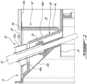
- Figs. 1 and 2 illustrate an example of such a thermally shielded probe. More particularly, Figs. 1 and 2 illustrate a probe 22 projecting through the exhaust duct and the LP turbine housing 24 to a location where a tip of the probe 22 is positioned adjacent to the LP turbine shaft for measuring an operating parameter (e.g. speed and/or torque) of the LP turbine 14a.
- an operating parameter e.g. speed and/or torque
- the exemplary probe 22 extends through a probe boss 32 mounted in a receiving hole defined at the top dead center of the exhaust duct 30 between the two diverging outlet conduit portions 30b, 30c thereof.
- the term "boss" is herein intended to generally refer to a mounting feature on a work piece. For instance, it can take the form of a protruding feature used to locate one component (e.g. a probe) within a pocket or hole of another component (e.g. the exhaust duct).
- the probe boss 32 may be provided in the form of a casting including a sleeve 32a and an outer flange 32b welded or otherwise suitably secured to the exhaust duct 30.
- the sleeve 32a has a slanted tubular portion that projects inwardly into the exhaust duct 30 in a "dead" air cavity 34 ( Fig. 2 ) radially between the LP turbine housing 24 the exhaust duct 30.
- the slanted tubular portion is aligned with an associated probe boss 36 provided on the turbine housing 24.
- the probes bosses 32, 36 provide a passage for the probe 22 through the exhaust case 15 and the turbine housing 24.
- the probe 22 extends through the registering probe bosses 32, 36 and into the LP turbine housing 24 next to the LP turbine shaft.
- the tip portion of the probe 22 is thermally shielded by the oil contained in the LP turbine housing 24.
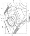
- a probe heat shield is provided in the cavity 34 to protect the upper portion of the probe 22 from heat radiations emanating from the exhaust duct 30.
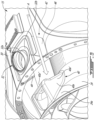
- the probe heat shield may be configured to create a heat shielding volume of air or air gap around the turbine probe 22 along a full radial extent of the cavity 34 between the exhaust duct 30 and the LP turbine housing 24 while allowing for the assembly of the exhaust duct 30 over the LP turbine housing 24 as shown in Fig. 5 .
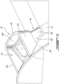
- the protective enclosure formed by the thermal blanket 40a on the LP turbine housing 24 only radially extends along a portion of the cavity 34. Indeed, the radially outer end of the thermal blanket 40a through which the probe 22 extends is spaced radially inwardly from the inner end of the probe boss 32 (also herein referred to as the second probe boss) on the exhaust duct 30 so as to permit axial assembly of the exhaust duct 30 over the LP turbine housing 24.
- the portion of the probe 22 projecting radially outwardly from the turbine housing thermal blanket 40a is thermally shielded by the second mating portion 42 of the heat shield, that is the portion of the heat shield projecting radially inwardly from the exhaust duct 30.
- first and second mating portions 40, 42 of the probe heat shield cooperate to surround the probe 22 radially across a full extent of the cavity 34.
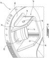
- the first and second mating portions 40, 42 of the heat shield have a radial overlap to account for thermal growth differential between the LP turbine housing 24 and the exhaust duct 30. Accordingly, in operation, the first and second mating portions 40, 42 of the probe heat shield can move relative to one another as a result of different thermal expansions between the exhaust duct 30 and the LP turbine housing 24 and yet still ensure the integrity of the insulation compartment they jointly form around the probe 22 in the cavity 34.
- the radial overlap is selected so that no radial gap is created between the first and second mating portions 40, 42 of the probe heat shield during engine operations.
- the second mating portion 42 of the heat shield comprises a thermal blanket 44 having a construction similar to that of the thermal blanket 40a used on the LP turbine housing 24 but structurally backed or reinforced by a support bracket 46 mounted to a radially inner surface 30a of the exhaust duct 30.
- the support bracket 46 can be made of sheet metal and is suitably attached to the exhaust duct 30, such as by welding, brazing or riveting.
- the thermal blanket 44 can be detachably mounted inside the support bracket 46 by any suitable means. According to the illustrated embodiment, fasteners, such as bolts 48 ( Fig. 4 ), are used to detachably attach the thermal blanket 44 to its support bracket 46.
Landscapes
- Engineering & Computer Science (AREA)
- Mechanical Engineering (AREA)
- General Engineering & Computer Science (AREA)
- Chemical & Material Sciences (AREA)
- Combustion & Propulsion (AREA)
- Supercharger (AREA)
- Exhaust Silencers (AREA)
Claims (11)
- Gasturbinentriebwerkabgasanordnung, umfassend:eine Sonde (22);ein Turbinengehäuse (24), das sich um eine Mittelachse (17) herum erstreckt und einen ersten Sondenansatz (36) aufweist;ein Abgasgehäuse (15), das das Turbinengehäuse (24) umgibt und einen zweiten Sondenansatz (32) aufweist, der mit dem ersten Sondenansatz (36) ausgerichtet ist, wobei sich die Sonde (22) durch den ersten Sondenansatz (36) und den zweiten Sondenansatz (32) erstreckt; undeinen Hohlraum (34), der sich radial zwischen dem Turbinengehäuse (24) und dem Abgasgehäuse (15) befindet,dadurch gekennzeichnet, dass die Gasturbinenabgasanordnung ferner umfasst:
ein Sondenhitzeschild, das einen ersten und einen zweiten Gegenabschnitt (40, 42) aufweist, die axial übereinander entlang der Mittelachse (17) und um die Sonde (22) herum in dem Hohlraum (34) gleitend angebracht sind, wobei der erste Gegenabschnitt (40) an einer radial äußeren Oberfläche des Turbinengehäuses (24) vorgesehen ist, wobei der zweite Gegenabschnitt (42) radial nach innen von dem Abgasgehäuse (15) in den Hohlraum (34) hineinragt. - Gasturbinentriebwerkabgasanordnung nach Anspruch 1, wobei der zweite Gegenabschnitt (42) des Sondenhitzeschilds einen U-förmigen Körper aufweist, der ein Paar sich axial erstreckender Arme (42a) aufweist, wobei der erste Gegenabschnitt (40) des Sondenhitzeschilds axial zwischen den sich axial erstreckenden Armen (42a) des U-förmigen Körpers aufgenommen ist.
- Gasturbinentriebwerkabgasanordnung nach Anspruch 2, wobei der zweite Sondenansatz (32) von dem Abgasgehäuse (15) radial nach innen in den Hohlraum (34) hineinragt und der U-förmige Körper den zweiten Sondenansatz (32) in dem Hohlraum (34) umgibt.
- Gasturbinentriebwerkabgasanordnung nach Anspruch 2 oder 3, wobei der U-förmige Körper radial nach innen in den Hohlraum (34) bis zu einer Stelle jenseits eines inneren Endes des zweiten Sondenansatzes (32) hineinragt, um eine radiale Überlappung mit dem ersten Gegenabschnitt (40) des Sondenhitzeschilds am Turbinengehäuse (24) zu bilden.
- Gasturbinentriebwerkabgasanordnung nach einem der Ansprüche 2 bis 4, wobei der U-förmige Körper eine Wärmedecke (44) umfasst, die strukturell mit einem an einer radial inneren Oberfläche (30a) des Abgasgehäuses (15) angebrachten Haltebügel (46) abgestützt ist.
- Gasturbinentriebwerkabgasanordnung nach Anspruch 5, wobei die Wärmedecke (44) abnehmbar im Inneren des Haltebügels (46) angebracht ist.
- Gasturbinentriebwerkabgasanordnung nach Anspruch 5 oder 6, wobei sich der Haltebügel (46) über einen größeren Abschnitt einer Oberfläche der Wärmedecke (44) erstreckt.
- Gasturbinentriebwerkabgasanordnung nach einem der vorhergehenden Ansprüche, wobei die ersten und zweiten Gegenabschnitte (40, 42) des Hitzeschilds ein Luftvolumen um die Sonde (22) herum definieren, wobei das Luftvolumen in Fluidverbindung mit einer Luftquelle außerhalb des Abgasgehäuses (15) steht.
- Gasturbinentriebwerkabgasanordnung nach einem der vorhergehenden Ansprüche, wobei das Abgasgehäuse (15) einen asymmetrischen doppelten Abgaskanal (30), der erste und zweite Auslassabschnitte (30b, 30c) aufweist, die von der Mittelachse (17) divergieren, um Verbrennungsgase abzuleiten, und wobei der zweite Sondenansatz (32) zwischen den ersten und zweiten Auslassabschnitten (30b, 30c) angeordnet ist.
- Gasturbinentriebwerkabgasanordnung nach Anspruch 9, wobei der zweite Sondenansatz (32) und der zweite Gegenabschnitt (42) des Sondenhitzeschilds im oberen Totpunkt des asymmetrischen dualen Abgaskanals (30) angeordnet sind.
- Gasturbinentriebwerk (10), umfassend:einen Verdichter (12), der zur Drehung um eine Achse (17) angebracht ist;eine Turbine (14), die antriebsmäßig mit dem Verdichter (12) verbunden ist; undeine Gasturbinentriebwerkabgasanordnung nach einem der vorhergehenden Ansprüche.
Applications Claiming Priority (1)
| Application Number | Priority Date | Filing Date | Title |
|---|---|---|---|
| US17/209,631 US11428122B1 (en) | 2021-03-23 | 2021-03-23 | Thermal protection for a gas turbine engine probe |
Publications (2)
| Publication Number | Publication Date |
|---|---|
| EP4063620A1 EP4063620A1 (de) | 2022-09-28 |
| EP4063620B1 true EP4063620B1 (de) | 2024-07-03 |
Family
ID=80930370
Family Applications (1)
| Application Number | Title | Priority Date | Filing Date |
|---|---|---|---|
| EP22163938.8A Active EP4063620B1 (de) | 2021-03-23 | 2022-03-23 | Wärmeschutz für eine sonde eines gasturbinentriebwerks |
Country Status (4)
| Country | Link |
|---|---|
| US (1) | US11428122B1 (de) |
| EP (1) | EP4063620B1 (de) |
| CA (1) | CA3152904A1 (de) |
| PL (1) | PL4063620T3 (de) |
Family Cites Families (17)
| Publication number | Priority date | Publication date | Assignee | Title |
|---|---|---|---|---|
| US4597675A (en) * | 1983-04-04 | 1986-07-01 | The Garrett Corporation | Mean temperature sensor |
| US5404760A (en) * | 1993-10-27 | 1995-04-11 | Westinghouse Electric Corporation | Blade path thermocouple and exhaust gas extraction probe for combustion turbines |
| US6037581A (en) * | 1996-01-15 | 2000-03-14 | Siemens Aktiengesellschaft | Device for recording a change in position at a turbine configuration |
| US7654093B2 (en) * | 2005-09-26 | 2010-02-02 | Pratt & Whitney Canada Corp. | Method of adjusting a triggering clearance and a trigger |
| US7913661B2 (en) | 2007-10-17 | 2011-03-29 | Honda Motor Co., Ltd. | Protective system for a crank angle sensor |
| US8997558B2 (en) * | 2011-03-29 | 2015-04-07 | General Electric Company | Combustor probe for gas turbine |
| US9631517B2 (en) * | 2012-12-29 | 2017-04-25 | United Technologies Corporation | Multi-piece fairing for monolithic turbine exhaust case |
| US9551281B2 (en) * | 2014-01-15 | 2017-01-24 | Pratt & Whitney Canada Corp. | Electric probe assembly, gas turbine engine having same and method of cooling same |
| US9605953B2 (en) * | 2014-10-30 | 2017-03-28 | Hamilton Sundstrand Corporation | Linkage assembly for sensor assembly and method of detecting angular position of a target through multiple structures |
| US9880059B2 (en) * | 2015-06-08 | 2018-01-30 | Siemens Energy, Inc. | Gas turbine exhaust diffuser mounted blade path thermocouple probe |
| US9897009B2 (en) | 2016-02-08 | 2018-02-20 | United Technologies Corporation | Flexible thermal blanket |
| US10883424B2 (en) | 2016-07-19 | 2021-01-05 | Pratt & Whitney Canada Corp. | Multi-spool gas turbine engine architecture |
| US10808624B2 (en) * | 2017-02-09 | 2020-10-20 | Pratt & Whitney Canada Corp. | Turbine rotor with low over-speed requirements |
| US11454128B2 (en) * | 2018-08-06 | 2022-09-27 | General Electric Company | Fairing assembly |
| US10794795B2 (en) * | 2018-09-14 | 2020-10-06 | Raytheon Technologies Corporation | Low profile embedded non-intrusive stress measurement system probe |
| US10816507B2 (en) * | 2019-03-20 | 2020-10-27 | Raytheon Technologies Corporation | Apparatus and method and system for inspecting a component of a gas turbine engine |
| US10876426B2 (en) * | 2019-04-09 | 2020-12-29 | Pratt & Whitney Canada Corp. | Removable turbine gaspath sensor |
-
2021
- 2021-03-23 US US17/209,631 patent/US11428122B1/en active Active
-
2022
- 2022-03-17 CA CA3152904A patent/CA3152904A1/en active Pending
- 2022-03-23 PL PL22163938.8T patent/PL4063620T3/pl unknown
- 2022-03-23 EP EP22163938.8A patent/EP4063620B1/de active Active
Also Published As
| Publication number | Publication date |
|---|---|
| PL4063620T3 (pl) | 2024-11-18 |
| CA3152904A1 (en) | 2022-09-23 |
| EP4063620A1 (de) | 2022-09-28 |
| US11428122B1 (en) | 2022-08-30 |
Similar Documents
| Publication | Publication Date | Title |
|---|---|---|
| EP4067625B1 (de) | Gasturbinentriebwerk mit einer messsonde | |
| US11781448B1 (en) | Shroud pin for gas turbine engine shroud | |
| EP0578461B1 (de) | Düsenhalterung für Turbinen | |
| EP3066318B1 (de) | Innendiffusorgehäuse für einen gasturbinenmotor | |
| EP2938857B1 (de) | Hitzeschild zur kühlung einer strebe | |
| EP2927595B1 (de) | Schutzmanschettenanordnung und verfahren zum entwurf | |
| EP3640541B1 (de) | Schlitzgekühlte brennkammer | |
| EP2551458A2 (de) | Schaufelkühl- und -abdichtsystem | |
| EP3211312A1 (de) | Brennkammeranordnung | |
| EP4299880A1 (de) | Sondenwärmeabschirmung | |
| EP4047191B1 (de) | Instrumentierter turbinenabgaskanal | |
| CA3145036A1 (en) | Torque probe cooling for gas turbine engine using external air | |
| EP2971683B1 (de) | Wärmetauschersystem für gasturbinenmotor | |
| EP4063620B1 (de) | Wärmeschutz für eine sonde eines gasturbinentriebwerks | |
| CN115680791A (zh) | 间隙控制组件 | |
| US11512646B2 (en) | Air starter with bearing cooling | |
| EP3748132A1 (de) | Ermüdungsbeständige schaufelaussenluftdichtung | |
| US11506080B2 (en) | Gas turbine engine probe cooling | |
| EP3708782B1 (de) | Boas und verfahren zur herstellung von boas mit ermüdungsbeständigen kühleinlässen | |
| EP3748133B1 (de) | Ermüdungsbeständige schaufelaussenluftdichtung | |
| EP3971401B1 (de) | Düse eines flugzeugantriebssystems mit internem strömungskanal | |
| US12044169B2 (en) | Sump arrangement for a gas turbine engine | |
| US20190376471A1 (en) | Deflection Mitigation Structure for Combustion System |
Legal Events
| Date | Code | Title | Description |
|---|---|---|---|
| PUAI | Public reference made under article 153(3) epc to a published international application that has entered the european phase |
Free format text: ORIGINAL CODE: 0009012 |
|
| STAA | Information on the status of an ep patent application or granted ep patent |
Free format text: STATUS: THE APPLICATION HAS BEEN PUBLISHED |
|
| AK | Designated contracting states |
Kind code of ref document: A1 Designated state(s): AL AT BE BG CH CY CZ DE DK EE ES FI FR GB GR HR HU IE IS IT LI LT LU LV MC MK MT NL NO PL PT RO RS SE SI SK SM TR |
|
| STAA | Information on the status of an ep patent application or granted ep patent |
Free format text: STATUS: REQUEST FOR EXAMINATION WAS MADE |
|
| 17P | Request for examination filed |
Effective date: 20230327 |
|
| RBV | Designated contracting states (corrected) |
Designated state(s): AL AT BE BG CH CY CZ DE DK EE ES FI FR GB GR HR HU IE IS IT LI LT LU LV MC MK MT NL NO PL PT RO RS SE SI SK SM TR |
|
| RIC1 | Information provided on ipc code assigned before grant |
Ipc: F01D 17/02 20060101AFI20231214BHEP |
|
| GRAP | Despatch of communication of intention to grant a patent |
Free format text: ORIGINAL CODE: EPIDOSNIGR1 |
|
| STAA | Information on the status of an ep patent application or granted ep patent |
Free format text: STATUS: GRANT OF PATENT IS INTENDED |
|
| INTG | Intention to grant announced |
Effective date: 20240125 |
|
| GRAS | Grant fee paid |
Free format text: ORIGINAL CODE: EPIDOSNIGR3 |
|
| GRAA | (expected) grant |
Free format text: ORIGINAL CODE: 0009210 |
|
| STAA | Information on the status of an ep patent application or granted ep patent |
Free format text: STATUS: THE PATENT HAS BEEN GRANTED |
|
| AK | Designated contracting states |
Kind code of ref document: B1 Designated state(s): AL AT BE BG CH CY CZ DE DK EE ES FI FR GB GR HR HU IE IS IT LI LT LU LV MC MK MT NL NO PL PT RO RS SE SI SK SM TR |
|
| REG | Reference to a national code |
Ref country code: CH Ref legal event code: EP |
|
| REG | Reference to a national code |
Ref country code: DE Ref legal event code: R096 Ref document number: 602022004223 Country of ref document: DE |
|
| REG | Reference to a national code |
Ref country code: LT Ref legal event code: MG9D |
|
| REG | Reference to a national code |
Ref country code: NL Ref legal event code: MP Effective date: 20240703 |
|
| PG25 | Lapsed in a contracting state [announced via postgrant information from national office to epo] |
Ref country code: PT Free format text: LAPSE BECAUSE OF FAILURE TO SUBMIT A TRANSLATION OF THE DESCRIPTION OR TO PAY THE FEE WITHIN THE PRESCRIBED TIME-LIMIT Effective date: 20241104 |
|
| REG | Reference to a national code |
Ref country code: AT Ref legal event code: MK05 Ref document number: 1700014 Country of ref document: AT Kind code of ref document: T Effective date: 20240703 |
|
| PG25 | Lapsed in a contracting state [announced via postgrant information from national office to epo] |
Ref country code: NL Free format text: LAPSE BECAUSE OF FAILURE TO SUBMIT A TRANSLATION OF THE DESCRIPTION OR TO PAY THE FEE WITHIN THE PRESCRIBED TIME-LIMIT Effective date: 20240703 |
|
| PG25 | Lapsed in a contracting state [announced via postgrant information from national office to epo] |
Ref country code: PT Free format text: LAPSE BECAUSE OF FAILURE TO SUBMIT A TRANSLATION OF THE DESCRIPTION OR TO PAY THE FEE WITHIN THE PRESCRIBED TIME-LIMIT Effective date: 20241104 Ref country code: NL Free format text: LAPSE BECAUSE OF FAILURE TO SUBMIT A TRANSLATION OF THE DESCRIPTION OR TO PAY THE FEE WITHIN THE PRESCRIBED TIME-LIMIT Effective date: 20240703 |
|
| PG25 | Lapsed in a contracting state [announced via postgrant information from national office to epo] |
Ref country code: NO Free format text: LAPSE BECAUSE OF FAILURE TO SUBMIT A TRANSLATION OF THE DESCRIPTION OR TO PAY THE FEE WITHIN THE PRESCRIBED TIME-LIMIT Effective date: 20241003 |
|
| PG25 | Lapsed in a contracting state [announced via postgrant information from national office to epo] |
Ref country code: FI Free format text: LAPSE BECAUSE OF FAILURE TO SUBMIT A TRANSLATION OF THE DESCRIPTION OR TO PAY THE FEE WITHIN THE PRESCRIBED TIME-LIMIT Effective date: 20240703 Ref country code: GR Free format text: LAPSE BECAUSE OF FAILURE TO SUBMIT A TRANSLATION OF THE DESCRIPTION OR TO PAY THE FEE WITHIN THE PRESCRIBED TIME-LIMIT Effective date: 20241004 |
|
| PG25 | Lapsed in a contracting state [announced via postgrant information from national office to epo] |
Ref country code: BG Free format text: LAPSE BECAUSE OF FAILURE TO SUBMIT A TRANSLATION OF THE DESCRIPTION OR TO PAY THE FEE WITHIN THE PRESCRIBED TIME-LIMIT Effective date: 20240703 |
|
| PG25 | Lapsed in a contracting state [announced via postgrant information from national office to epo] |
Ref country code: LV Free format text: LAPSE BECAUSE OF FAILURE TO SUBMIT A TRANSLATION OF THE DESCRIPTION OR TO PAY THE FEE WITHIN THE PRESCRIBED TIME-LIMIT Effective date: 20240703 |
|
| PG25 | Lapsed in a contracting state [announced via postgrant information from national office to epo] |
Ref country code: AT Free format text: LAPSE BECAUSE OF FAILURE TO SUBMIT A TRANSLATION OF THE DESCRIPTION OR TO PAY THE FEE WITHIN THE PRESCRIBED TIME-LIMIT Effective date: 20240703 Ref country code: IS Free format text: LAPSE BECAUSE OF FAILURE TO SUBMIT A TRANSLATION OF THE DESCRIPTION OR TO PAY THE FEE WITHIN THE PRESCRIBED TIME-LIMIT Effective date: 20241103 |
|
| PG25 | Lapsed in a contracting state [announced via postgrant information from national office to epo] |
Ref country code: HR Free format text: LAPSE BECAUSE OF FAILURE TO SUBMIT A TRANSLATION OF THE DESCRIPTION OR TO PAY THE FEE WITHIN THE PRESCRIBED TIME-LIMIT Effective date: 20240703 |
|
| PG25 | Lapsed in a contracting state [announced via postgrant information from national office to epo] |
Ref country code: RS Free format text: LAPSE BECAUSE OF FAILURE TO SUBMIT A TRANSLATION OF THE DESCRIPTION OR TO PAY THE FEE WITHIN THE PRESCRIBED TIME-LIMIT Effective date: 20241003 Ref country code: ES Free format text: LAPSE BECAUSE OF FAILURE TO SUBMIT A TRANSLATION OF THE DESCRIPTION OR TO PAY THE FEE WITHIN THE PRESCRIBED TIME-LIMIT Effective date: 20240703 |
|
| PG25 | Lapsed in a contracting state [announced via postgrant information from national office to epo] |
Ref country code: RS Free format text: LAPSE BECAUSE OF FAILURE TO SUBMIT A TRANSLATION OF THE DESCRIPTION OR TO PAY THE FEE WITHIN THE PRESCRIBED TIME-LIMIT Effective date: 20241003 Ref country code: NO Free format text: LAPSE BECAUSE OF FAILURE TO SUBMIT A TRANSLATION OF THE DESCRIPTION OR TO PAY THE FEE WITHIN THE PRESCRIBED TIME-LIMIT Effective date: 20241003 Ref country code: LV Free format text: LAPSE BECAUSE OF FAILURE TO SUBMIT A TRANSLATION OF THE DESCRIPTION OR TO PAY THE FEE WITHIN THE PRESCRIBED TIME-LIMIT Effective date: 20240703 Ref country code: IS Free format text: LAPSE BECAUSE OF FAILURE TO SUBMIT A TRANSLATION OF THE DESCRIPTION OR TO PAY THE FEE WITHIN THE PRESCRIBED TIME-LIMIT Effective date: 20241103 Ref country code: HR Free format text: LAPSE BECAUSE OF FAILURE TO SUBMIT A TRANSLATION OF THE DESCRIPTION OR TO PAY THE FEE WITHIN THE PRESCRIBED TIME-LIMIT Effective date: 20240703 Ref country code: GR Free format text: LAPSE BECAUSE OF FAILURE TO SUBMIT A TRANSLATION OF THE DESCRIPTION OR TO PAY THE FEE WITHIN THE PRESCRIBED TIME-LIMIT Effective date: 20241004 Ref country code: FI Free format text: LAPSE BECAUSE OF FAILURE TO SUBMIT A TRANSLATION OF THE DESCRIPTION OR TO PAY THE FEE WITHIN THE PRESCRIBED TIME-LIMIT Effective date: 20240703 Ref country code: ES Free format text: LAPSE BECAUSE OF FAILURE TO SUBMIT A TRANSLATION OF THE DESCRIPTION OR TO PAY THE FEE WITHIN THE PRESCRIBED TIME-LIMIT Effective date: 20240703 Ref country code: BG Free format text: LAPSE BECAUSE OF FAILURE TO SUBMIT A TRANSLATION OF THE DESCRIPTION OR TO PAY THE FEE WITHIN THE PRESCRIBED TIME-LIMIT Effective date: 20240703 Ref country code: AT Free format text: LAPSE BECAUSE OF FAILURE TO SUBMIT A TRANSLATION OF THE DESCRIPTION OR TO PAY THE FEE WITHIN THE PRESCRIBED TIME-LIMIT Effective date: 20240703 |
|
| REG | Reference to a national code |
Ref country code: DE Ref legal event code: R097 Ref document number: 602022004223 Country of ref document: DE |
|
| PGFP | Annual fee paid to national office [announced via postgrant information from national office to epo] |
Ref country code: DE Payment date: 20250218 Year of fee payment: 4 |
|
| PG25 | Lapsed in a contracting state [announced via postgrant information from national office to epo] |
Ref country code: RO Free format text: LAPSE BECAUSE OF FAILURE TO SUBMIT A TRANSLATION OF THE DESCRIPTION OR TO PAY THE FEE WITHIN THE PRESCRIBED TIME-LIMIT Effective date: 20240703 Ref country code: SM Free format text: LAPSE BECAUSE OF FAILURE TO SUBMIT A TRANSLATION OF THE DESCRIPTION OR TO PAY THE FEE WITHIN THE PRESCRIBED TIME-LIMIT Effective date: 20240703 Ref country code: DK Free format text: LAPSE BECAUSE OF FAILURE TO SUBMIT A TRANSLATION OF THE DESCRIPTION OR TO PAY THE FEE WITHIN THE PRESCRIBED TIME-LIMIT Effective date: 20240703 |
|
| PG25 | Lapsed in a contracting state [announced via postgrant information from national office to epo] |
Ref country code: EE Free format text: LAPSE BECAUSE OF FAILURE TO SUBMIT A TRANSLATION OF THE DESCRIPTION OR TO PAY THE FEE WITHIN THE PRESCRIBED TIME-LIMIT Effective date: 20240703 |
|
| PGFP | Annual fee paid to national office [announced via postgrant information from national office to epo] |
Ref country code: PL Payment date: 20250221 Year of fee payment: 4 Ref country code: FR Payment date: 20250218 Year of fee payment: 4 Ref country code: CZ Payment date: 20250225 Year of fee payment: 4 |
|
| PG25 | Lapsed in a contracting state [announced via postgrant information from national office to epo] |
Ref country code: SK Free format text: LAPSE BECAUSE OF FAILURE TO SUBMIT A TRANSLATION OF THE DESCRIPTION OR TO PAY THE FEE WITHIN THE PRESCRIBED TIME-LIMIT Effective date: 20240703 Ref country code: IT Free format text: LAPSE BECAUSE OF FAILURE TO SUBMIT A TRANSLATION OF THE DESCRIPTION OR TO PAY THE FEE WITHIN THE PRESCRIBED TIME-LIMIT Effective date: 20240703 |
|
| PLBE | No opposition filed within time limit |
Free format text: ORIGINAL CODE: 0009261 |
|
| STAA | Information on the status of an ep patent application or granted ep patent |
Free format text: STATUS: NO OPPOSITION FILED WITHIN TIME LIMIT |
|
| 26N | No opposition filed |
Effective date: 20250404 |
|
| PG25 | Lapsed in a contracting state [announced via postgrant information from national office to epo] |
Ref country code: SE Free format text: LAPSE BECAUSE OF FAILURE TO SUBMIT A TRANSLATION OF THE DESCRIPTION OR TO PAY THE FEE WITHIN THE PRESCRIBED TIME-LIMIT Effective date: 20240703 |
|
| PG25 | Lapsed in a contracting state [announced via postgrant information from national office to epo] |
Ref country code: MC Free format text: LAPSE BECAUSE OF FAILURE TO SUBMIT A TRANSLATION OF THE DESCRIPTION OR TO PAY THE FEE WITHIN THE PRESCRIBED TIME-LIMIT Effective date: 20240703 |
|
| REG | Reference to a national code |
Ref country code: CH Ref legal event code: H13 Free format text: ST27 STATUS EVENT CODE: U-0-0-H10-H13 (AS PROVIDED BY THE NATIONAL OFFICE) Effective date: 20251024 |
|
| PG25 | Lapsed in a contracting state [announced via postgrant information from national office to epo] |
Ref country code: LU Free format text: LAPSE BECAUSE OF NON-PAYMENT OF DUE FEES Effective date: 20250323 |
|
| REG | Reference to a national code |
Ref country code: BE Ref legal event code: MM Effective date: 20250331 |
|
| PG25 | Lapsed in a contracting state [announced via postgrant information from national office to epo] |
Ref country code: BE Free format text: LAPSE BECAUSE OF NON-PAYMENT OF DUE FEES Effective date: 20250331 |
|
| PG25 | Lapsed in a contracting state [announced via postgrant information from national office to epo] |
Ref country code: CH Free format text: LAPSE BECAUSE OF NON-PAYMENT OF DUE FEES Effective date: 20250331 |
|
| PG25 | Lapsed in a contracting state [announced via postgrant information from national office to epo] |
Ref country code: IE Free format text: LAPSE BECAUSE OF NON-PAYMENT OF DUE FEES Effective date: 20250323 |