EP3550133B1 - Abgaskanal für ein gasturbinentriebwerk - Google Patents
Abgaskanal für ein gasturbinentriebwerk Download PDFInfo
- Publication number
- EP3550133B1 EP3550133B1 EP19154603.5A EP19154603A EP3550133B1 EP 3550133 B1 EP3550133 B1 EP 3550133B1 EP 19154603 A EP19154603 A EP 19154603A EP 3550133 B1 EP3550133 B1 EP 3550133B1
- Authority
- EP
- European Patent Office
- Prior art keywords
- outlet
- conduit
- exhaust duct
- splitter
- clocking
- Prior art date
- Legal status (The legal status is an assumption and is not a legal conclusion. Google has not performed a legal analysis and makes no representation as to the accuracy of the status listed.)
- Active
Links
Images


Classifications
-
- F—MECHANICAL ENGINEERING; LIGHTING; HEATING; WEAPONS; BLASTING
- F02—COMBUSTION ENGINES; HOT-GAS OR COMBUSTION-PRODUCT ENGINE PLANTS
- F02K—JET-PROPULSION PLANTS
- F02K1/00—Plants characterised by the form or arrangement of the jet pipe or nozzle; Jet pipes or nozzles peculiar thereto
- F02K1/40—Nozzles having means for dividing the jet into a plurality of partial jets or having an elongated cross-section outlet
-
- F—MECHANICAL ENGINEERING; LIGHTING; HEATING; WEAPONS; BLASTING
- F01—MACHINES OR ENGINES IN GENERAL; ENGINE PLANTS IN GENERAL; STEAM ENGINES
- F01D—NON-POSITIVE DISPLACEMENT MACHINES OR ENGINES, e.g. STEAM TURBINES
- F01D25/00—Component parts, details, or accessories, not provided for in, or of interest apart from, other groups
- F01D25/30—Exhaust heads, chambers, or the like
-
- F—MECHANICAL ENGINEERING; LIGHTING; HEATING; WEAPONS; BLASTING
- F02—COMBUSTION ENGINES; HOT-GAS OR COMBUSTION-PRODUCT ENGINE PLANTS
- F02C—GAS-TURBINE PLANTS; AIR INTAKES FOR JET-PROPULSION PLANTS; CONTROLLING FUEL SUPPLY IN AIR-BREATHING JET-PROPULSION PLANTS
- F02C6/00—Plural gas-turbine plants; Combinations of gas-turbine plants with other apparatus; Adaptations of gas-turbine plants for special use
- F02C6/20—Adaptations of gas-turbine plants for driving vehicles
- F02C6/206—Adaptations of gas-turbine plants for driving vehicles the vehicles being airscrew driven
-
- F—MECHANICAL ENGINEERING; LIGHTING; HEATING; WEAPONS; BLASTING
- F02—COMBUSTION ENGINES; HOT-GAS OR COMBUSTION-PRODUCT ENGINE PLANTS
- F02K—JET-PROPULSION PLANTS
- F02K1/00—Plants characterised by the form or arrangement of the jet pipe or nozzle; Jet pipes or nozzles peculiar thereto
- F02K1/78—Other construction of jet pipes
-
- F—MECHANICAL ENGINEERING; LIGHTING; HEATING; WEAPONS; BLASTING
- F05—INDEXING SCHEMES RELATING TO ENGINES OR PUMPS IN VARIOUS SUBCLASSES OF CLASSES F01-F04
- F05D—INDEXING SCHEME FOR ASPECTS RELATING TO NON-POSITIVE-DISPLACEMENT MACHINES OR ENGINES, GAS-TURBINES OR JET-PROPULSION PLANTS
- F05D2250/00—Geometry
- F05D2250/50—Inlet or outlet
- F05D2250/52—Outlet
-
- F—MECHANICAL ENGINEERING; LIGHTING; HEATING; WEAPONS; BLASTING
- F05—INDEXING SCHEMES RELATING TO ENGINES OR PUMPS IN VARIOUS SUBCLASSES OF CLASSES F01-F04
- F05D—INDEXING SCHEME FOR ASPECTS RELATING TO NON-POSITIVE-DISPLACEMENT MACHINES OR ENGINES, GAS-TURBINES OR JET-PROPULSION PLANTS
- F05D2250/00—Geometry
- F05D2250/70—Shape
- F05D2250/73—Shape asymmetric
Definitions
- the application relates generally to gas turbine engines and, more particularly, to exhaust ducts in gas turbine engines.
- Exhaust ducts are disposed after the turbine section and evacuate gases that have been used to power the turbine.
- the flow entering into the outlet may be swirling and have a substantial velocity which may be used as a residual thrust to the engine. Swirling of the gases may produce total pressure loss which in turn may reduce the residual thrust available.
- US 3 388 550 A discloses a prior art exhaust duct.
- US 3 146 590 A discloses a prior art power system with energy dividing means.
- an exhaust duct for exhausting combustion gases of a gas turbine engine as recited in claim 1.
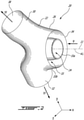
- FIG. 1 illustrates a gas turbine engine 10, in this example a turboprop engine, of a type preferably provided for use in subsonic flight, generally comprising in serial flow communication along an engine axis 11 (parallel to the X axis of the orthogonal axes shown in the drawings), a propeller 12 through which ambient air is propelled, a compressor section 14 for pressurizing the air, a combustor 16 in which the compressed air is mixed with fuel and ignited for generating an annular stream of hot combustion gases, and a turbine section 18 for extracting energy from the combustion gases and communicating this energy to the propeller 12.
- the exhaust gases are expelled via an exhaust duct 20.
- the exhaust gases are illustrated by arrows IF and EF, indicating the incoming flow and outlet flow relative to the exhaust duct 20 (see also Figs. 2 and 3 ).
- the exhaust duct 20, in this embodiment a dual ports exhaust duct, is formed by a generally Y-shaped body 22.
- the body 22 defines a fluid flow passage(s) about a central bore 24 for accommodating a shaft engine.
- the fluid flow passage of the annular body 22 generally includes an inlet conduit 26 through which the bore 24 extends, and in this example two outlet or exhaust conduits 30, 32 branching off from the inlet conduit 26.
- the inlet and outlet conduits 26, 30, 32 may adopt various configurations. For instance, they can take the form of cylindrically straight or curved conduits. If desired the body 22 may include more than two outlet conduits 30, 32.
- the inlet conduit 26 may be provided in the form of an annular inlet conduit 33 wherein the first (inlet) 26, second and third (exhaust or outlet) conduits 30, 32 connect and communicate.
- the outlet conduits 30, 32 may not be perpendicularly positioned relative to the inlet conduit 26 (i.e. be purely radially oriented with respect thereto), but rather may extend both radially and axially with respect thereto. Therefore, the body 22 could adopt various configurations including T-shaped and Y-shaped configurations. It is understood that any suitable configurations for the inlet and exhaust conduits may be used.
- the inlet conduit 26 has an axial extension extending about a centerline A1 that, in this example, is aligned with the engine axis 11 ( and thus parallel to the X axis of the X-Y-Z orthogonal axes shown in the drawings) of the gas turbine engine 10.
- the term "centerline” is herein intended to generally refer to line joining the centres of the annuli making up the conduit along its length, which corresponds to the general axis of the conduit. It is understood, however that the conduit need not be exactly circular in cross-section.
- the inlet conduit 26 includes an inlet end 34 located adjacent the turbine section 18. The inlet end 34 receives the inlet flow IF of exhaust gases from the turbine section 18.
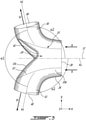
- the outlet conduits 30, 32 are generally cylindrical in shape in this example (though any suitable shape may be employed) and have respective outlet centerlines A2 and A3 which extend at an angle ⁇ 1, as shown in FIG. 3 , relative to each other.
- the centerlines A2 and A3 of the outlet conduits 30, 32 also extend at an angle, in this example the same angle ⁇ 2, relative to the centerline A1.
- the outlet conduits 30, 32 have corresponding inlet ends 37, 39 ( FIG. 5 ) and outlet ends, or outlet ports 38, 40 (also shown in FIG. 1 ) of the exhaust duct 20.
- the inlet ends 37, 39 are defined at the intersection between the conduit 33 and the outlet conduits 30, 32, as shown schematically by the dotted lines 37, 39 in FIG. 5 .
- the conduit 33 is annular about centerline A1, which also defines the central axis of the conduit 33.
- the conduit 33 has inner peripheral wall 33a and outer peripheral wall 33b.
- the outer wall 33b is a circumscribing wall of the conduit 33, and constitutes a periphery of the conduit 33.
- the conduit 33 may include two circumferentially spaced-apart splitters 42.
- the splitters 42 may take the form of raises or bumps formed inside the body 22 at a bottom 33c of the conduit 33 and project in a direction toward the inlet conduit 26.
- the splitters 42 are configured to split the inlet flow IF upstream of the flow impacting the bottom or downstream end 33c of the conduit 33, and to deflect the inlet flow IF into the multiple (two, in this example) outlet flows EF to be directed to the outlet ports 38, 40.
- Splitters 42 may be omitted (for instance the body 22 may be a T-shaped body), and the inlet flow IF could split when impacting the bottom 33c of the conduit 33.
- the exhaust duct 20 is clocked to enhance flow rate therethrough toward the outlet ports 38, 40.
- the clocking may be of the splitters 42 and/or the outlet conduits 30, 32. Clocking, as will be apparent below, refers to the angular position of the splitters 42 and/or outlet conduits 30, 32 (as the case may be) relative to the axis A1.
- the splitters 242 and outlet conduits 230, 232 in that case are a symmetric "mirror-image" relative to a vertical reference plane V (X-Z plane) and/or the horizontal plane H (X-Y plane).
- the clocking of the exhaust conduits may be characterised by an angle ⁇ 2 defined between the centreline A3 and a radius of conduit 33 at outer wall 33b at the point P where the outer wall 33b intersects centreline A3, as projected in the Y-Z plane.
- ⁇ 2 is non-zero (as is the case in Fig. 7A )
- ⁇ 2 greater than zero is a feature that is indicative of conduit clocking "earlier" in the flow swirl, or upstream relative to the swirl direction. More discussion on the effects of such clocking are below.
- such clocking of the outlet conduits also results in a lateral offset A ( Fig.
- the clocking may be arranged such that the peripheral wall of the outlet conduits 30, 32 intersect the body of conduit 33 approximately tangentially on one side of the conduits 30,32.
- clocking of splitter(s) 42 may characterised by an angle ⁇ 4 defined between an outlet centerline A2, A3 and the splitter line L1 passing through the adjacent splitter 42 and the centre A1, as projected in the projection Y-Z plane.
- ⁇ 4 is less than 90 degrees but greater than 0 (i.e. the outlet centerline A2, A3 is not perpendicular to the splitter line L1). This feature is indicative of splitter clocking towards one outlet conduit and away from the other.
- clocking of the splitter is beneficial when it splits the flow "earlier", or upstream relative to the swirl direction, and so ⁇ 4 being less than 90° indicates a clocking upstream of the splitter 42. Since ⁇ 7 is complementary to ⁇ 4, by corollary ⁇ 7 increases greater than 90°.
- FIG. 3 shows clocking of both splitters and outlet conduits
- beneficial results may be achieved by clocking only one of these features and not the other.
- common reference numerals are used for outlet clock angle ⁇ 2 and splitter clock angle ⁇ 4 for each outlet and splitter, respectively, though it will be understood they need not be the same for both (all) splitters and/or outlets.
- the exhaust duct will have a rotational symmetry about axis A1. Such symmetry is not essential to the present concept.
- Lateral offsets A, A' are also zero, meaning the centerlines are coaxial and pass through centre/centreline A1.
- the clocking may be configured to enhance the efficiency of the exhaust duct 20 by taking advantage of the swirl of the inlet flow IF.
- Swirl induced by the general operation of the gas turbine engine 10, may lead to pressure losses and, thus, is usually sought to be reduced in exhaust ducts.
- Swirl of the inlet flow IF travelling in a swirl direction illustrated by arrow S in FIGs. 4 and 5 , may be characterised by a swirl angle (not indicated) between a tangential component of the velocity and an axial component of the velocity.
- swirl is referred to herein is the average swirl angle of the inlet flow IF.
- the swirl direction is in the counter-clockwise direction. It is contemplated that in some cases swirl may optionally be decreased by vanes, for example disposed at or near the inlets 37, 39.
- vanes for example disposed at or near the inlets 37, 39.
- FIG. 5 depicts schematic views of an exhaust duct 20 according to another aspect of the present description (in dotted line) superimposed upon the unclocked prior art exhaust duct 220 (in solid lines) of FIG. 7A .
- the clocking of the duct 20 may be achieved, in an example, by having the splitters 42 of the exhaust duct 20 clocked in a direction opposite to the swirl direction S of the inlet flow IF.
- the clocking may be defined by angle ⁇ 1 between the vertical plane V (or any other X-Z plane) and splitter line L1, a line in the Y-Z plane passing through centre A1 and a splitter 42.
- the particular alignment of splitters 42 results in coaxial splitter lines L1, but this is a matter of design choice and does not need to be so.
- the splitters 42 deflect inlet flow IF toward inlets 37, 39 of the outlet conduits 30, 32, and by redirecting the inlet flow IF "earlier", i.e.
- the inlet flow IF may be directed downstream toward the adjacent outlet conduit 30, 32 earlier which may beneficially result in less pressure loss and increased flow rate.
- the inlet flow IF may thus spend less time swirling in the conduit 33, and as a result, total pressure loss may be decreased.
- the outlet flow EF can be used as a residual thrust to the engine 10, total pressure loss is preferably as minimal as optimal.
- the splitter clock angle ⁇ 4/ ⁇ 7 may be chosen as a function of the swirl angle of the inlet flow IF. For example, larger swirl angles may require greater clocking.
- the angle ⁇ 7 is preferably not so big (and by corollary ⁇ 4 not so small) that the splitter 42 become aligned with the inlets 37, 39 of the upstream outlet conduit 30, 32 and obstruct the flow through the inlets 37, 39.
- FIG. 6A shows an example of an exhaust duct 120 according to the present description having clocked outlet conduits (not indicated) but unclocked splitters 142 (i.e. the splitters are located on the vertical line V contained in central plane X-Z), and FIG. 6B shows an example of a similar exhaust duct 120' but also having clocked splitters 142'.
- the area of the expected reverse flow RF is schematically illustrated by hatched shading, and a reversing arrow RF.
- the area of the expected reverse flow RF is smaller in the case of the exhaust duct 120' as a result of having clocked splitters 142' positions more closely relative to the exhaust duct 120 than the area of the expected reverse flow RF in the exhaust duct 120 having unclocked splitters 142.
- the total pressure loss may be reduced relative to the reverse flow RF in the exhaust duct 120.
- the exhaust duct 20 shown in FIGs. 4-5 has clocked splitters 42, it is contemplated that the exhaust duct 20 could have unlocked splitters (e.g. as shown in FIGs. 6A or 7B ) or no splitters at all.
- the outlet conduits 30, 32 of the exhaust duct 20 may be clocked in a direction opposite to the swirl direction S, as shown in the examples of FIGs. 4 and 5 , so that the swirling incoming flow IF is more easily (i.e. with less loss) directed into the outlet conduits 30, 32.
- the clocking is observed from a front of the exhaust duct 20, as shown in FIG. 4 . Clocking the outlet conduits 30, 32 allows to position the inlets 37, 39 of the outlet conduits 30, 32 to reduce the turning of the incoming flow IF when the flow transitions from the conduit 33 to the outlet conduits 30, 32.
- Clocking thus may provide for a smoother, and more tangentially-directed transition flow from the conduit 33 to the outlet conduits 30, 32, as illustrated by the arrow 52 in FIG. 4 and FIG. 5 , as compared to the transition flow direction illustrated by arrow 53 in the superimposed unclocked exhaust duct 220 in FIG. 5 .
- a smoother transition may also manifest itself as a relatively smaller total pressure loss for the outlet.
- the amount of outlet conduit clocking may be adjusted to suit particular design needs.
- the example of FIG. 4 has outlet conduit clocking such that the outlet conduits have outer surface approximately tangential with the inlet conduit 33.
- the outlet conduits are clocked, or offset, to a lesser extent (that is ⁇ 2 in FIG.4 is greater than ⁇ 2 in FIG. 5 ).
- centerline angle ⁇ 3 (i.e. the angle between centerline A3 and the horizontal plane H, as projected in the Y-Z plane) locates a position of the outlet centerline A3 of the conduit 32 relative to the horizontal plane when projected in the Y-Z plane.
- the angle ⁇ 3 is the oriented angle from the outlet centerline A3 to the horizontal plane H (plane Y-Z), as projected in the projection plane PP (plane Y-Z).
- the intersection point P3 has to be disposed away from the horizontal line intersecting the centerline A1.
- the clocking of the outlet conduits 30, 32 may be characterised in the example of Fig. 4 by having the outlet centerlines A2, A3 laterally offset from one another by a distance A, and offset by a distance A'; from a parallel line passing through axis A1 projected in the Y-Z plane.
- the offset A' for each outlet need not be the same and the amount of clocking may vary (compare FIGS. 4 and 5 , for example) according to design requirements.
- clocking is in the direction opposite of swirl direction S.
- FIG. 7A illustrates the prior art exhaust duct 220 having unclocked conduits 230, 232 and unclocked splitters 242.
- FIG. 7B illustrates an exhaust duct 220' having clocked outlet conduits 230', 232'.
- outlet centerlines A2 and A3 of the conduits 230', 232' are clocked by the outlet clocking angle angle ⁇ 2.
- the conduits 230', 232' do not have an inclination angle ⁇ 3 (see Fig. 4 ) between the centerlines A2, A3 and horizontal plane H is zero, that is, the centrelines A2, A3 are parallel to the horizontal plane H. From Fig.
- the two outlet conduits 230' and 232' extends through the circumscribing wall of the annular inlet conduit 233 along respective outlet centerlines A2, A3 that are distinct from one another (i.e. laterally offset A, A').
- the outlet centerlines A2, A3 of the at least two outlet conduits intersect the circumscribing wall 233b of the annular inlet conduit at respective intersection points P2, P3 and a radius R of the annular inlet conduit passes through each of the intersection points P2, P3 at the angle ⁇ 2.
- Clocking is in a direction opposite to an anticipated swirl direction S of the combustion gases in the inlet conduit. In an example where the swirling direction S is counter-clockwise, the outlet conduits 30, 32 are clocked in the clockwise direction.
- the outlet clocking angle ⁇ 2 may provide a more smooth transition from the conduit 233 to the outlet conduits 230, 232, as illustrated by the arrow 52 in FIG. 7B , compared to a prior art "unclocked" design in FIG. 7A .
- the clocking of the outlet conduits 230', 232' in the direction opposite to the swirling flow S may also be characterised by a tangent angle ⁇ 6 (shown in FIG. 7B as the angle between the intersection P3 of the centreline A3 and a tangent T to the periphery of the conduit 33) that acute and, it will be understood, is equal to 90°- ⁇ 2.
- the tangent angle ⁇ 6 is oriented from the outlet centerline A3 to a tangent T to the periphery of the conduit 233 (i.e. circumscribing wall 233b, not indicated in FIG. 7B ), as projected in the Y-Z plane.
- outlet conduits 230', 232' were to be clocked in same the direction of the swirling flow S, the tangent angle ⁇ 6 would be obtuse, while unclocked outlet conduits like FIG. 7A have an angle ⁇ 6 of 90°.
- a similar angle ⁇ 6 may be measured in respect of conduit 230' and its centreline A2, though the angle may not be the same magnitude, depending on conduit 230' placement.
- the presence of, and/or amount of, clocking of the splitters 42 and the outlet conduits 30, 32 may be chosen independently from one another, though in practice they are both related to inlet swirl angle.
- an exhaust duct 20 may have clocking of the splitters 42 only (in this case, the outlet centerlines A2, A3 of the outlet conduits 30, 32 would be coaxial), or clocking of the outlet conduits 30, 32 only (in this case, the outlet centerlines A2, A3 of the outlet conduits 30, 32 are non-coaxial, and distinct, and in some examples parallel. ).
- outlet conduit clocking may be characterised by a non-zero, positive conduit clock angle ⁇ 2
- splitter clocking may be characterised by a splitter clock angle ⁇ 4 that is less than 90° (or ⁇ 7 greater than 90°).
- an exhaust duct for exhausting combustion gases of a gas turbine engine, the exhaust duct comprising: an annular inlet conduit centered relative to a point of origin of an axis system of X-Y-Z orthogonal axes and having an axial extension along the X axis, and at least two outlet conduits branching off from the annular inlet conduit, the at least two outlet conduits being offset from one another as viewed when projected in plane Y-Z, and wherein the at least two outlet conduits are offset circumferentially upstream from the Y axis relative to an anticipated swirling flow direction of the combustion gases.
- an exhaust duct for exhausting a swirling flow of combustion gases of a gas turbine engine defining X-Y-Z orthogonal axes, the exhaust duct comprising: an annular inlet conduit having an axial extension along the X axis, and at least two outlet conduits branching off from the annular inlet conduit, the at least two outlet conduits being offset from one another as viewed when projected in plane Y-Z, and wherein the at least two outlet conduits are clocked about the annular inlet conduit in a direction opposite to an anticipated swirling flow direction of the combustion gases.
- an exhaust duct for a gas turbine engine comprising: a body having an annular conduit defining a central axis in an axial direction, the annular conduit having an axially disposed inlet conduit for receiving a swirling inlet flow from a turbine section of the gas turbine engine, the body having at least two outlet conduits connected to a circumscribing wall of the conduit, each of the outlet conduits having an outlet centerline, the outlet centerlines being distinct, and when projected onto a projection plane perpendicular to the central axis the outlet centerlines being offset from the central axis.
- an exhaust duct for a gas turbine engine comprising a body defining an annular conduit defining a central axis in an axial direction, the annular conduit having an axially disposed inlet conduit for receiving a swirling inlet flow from a turbine section of the gas turbine engine, and at least two outlet conduits branching off from an outer circumscribing wall of the annular conduit, the annular conduit including diametrically opposed splitters, a splitter line joining the opposed splitters, the body being dissymmetric relative to an axially oriented plane containing the splitter line.
- turbo-prop engine is described herein, the above described splitter could be used in a turbo-shaft engine.
- the examples are rotationally symmetric, other designs may be provided. Any suitable number of exhaust outlets may be provided, i.e. 2, 3 or more.
- the configuration of the ducts, conduits, and splitters may be any as suitable.
Landscapes
- Engineering & Computer Science (AREA)
- Mechanical Engineering (AREA)
- General Engineering & Computer Science (AREA)
- Chemical & Material Sciences (AREA)
- Combustion & Propulsion (AREA)
- Supercharger (AREA)
- Exhaust Silencers (AREA)
Claims (2)
- Abgaskanal (20) zum Ablassen von Verbrennungsgasen eines Gasturbinenmotors (10), wobei der Abgaskanal (20) Folgendes umfasst: eine ringförmige Einlassleitung (26), die eine Achse (A1) aufweist, eine äußere Wand (33b), die einen Radius (R) von der Achse (A1) aufweist, wobei die Einlassleitung (26) so konfiguriert ist, dass sie Verbrennungsgase im Allgemeinen in die axiale Richtung und mit einer Wirbelrichtung um die Achse (A1) leitet, wobei der Abgaskanal (20) ferner mindestens zwei Auslassleitungen (30, 32) umfasst, die sich im Allgemeinen radial nach außen von der Einlassleitung (26) entlang jeweiliger Auslassmittellinien (A2, A3) erstrecken,wobei die Einlassleitung (26) mindestens zwei Aufteilungsvorrichtungen (42) darin aufweist, wobei jede Aufteilungsvorrichtung (42) stromaufwärts einer jeweiligen Auslassleitung (30, 32) in Bezug auf die Wirbelrichtung liegt, wobei jede Aufteilungsvorrichtung (42) eine Aufteilungsvorrichtungslinie (L1) definiert, die radial durch die Aufteilungsvorrichtung (42) und die Achse (A1) verläuft, wobei die Aufteilungsvorrichtung (42) relativ zur Mittellinie (A2, A3) der jeweiligen stromabwärtigen Auslassleitung (30, 32) in einem Taktungswinkel (θ7) angeordnet ist, der zwischen der jeweiligen Mittellinie (A2, A3) und der Aufteilungsvorrichtungslinie (L1) definiert ist, wenn sie in einer Ebene projiziert werden, die orthogonal zur Achse (A1) ist, dadurch gekennzeichnet, dass
der Taktungswinkel (θ7) größer als 90° ist,wobei jede Aufteilungsvorrichtung (42) stromaufwärts der jeweiligen Auslassleitung (30, 32) in Bezug auf die Wirbelrichtung getaktet ist. - Abgaskanal (20) nach Anspruch 1, wobei die jeweiligen Winkel (θ7) bei jeder Aufteilungsvorrichtung (42) einander gleichen.
Applications Claiming Priority (2)
| Application Number | Priority Date | Filing Date | Title |
|---|---|---|---|
| US201462093080P | 2014-12-17 | 2014-12-17 | |
| EP15200764.7A EP3043056B1 (de) | 2014-12-17 | 2015-12-17 | Abgaskanal für einen gasturbinenmotor |
Related Parent Applications (2)
| Application Number | Title | Priority Date | Filing Date |
|---|---|---|---|
| EP15200764.7A Division EP3043056B1 (de) | 2014-12-17 | 2015-12-17 | Abgaskanal für einen gasturbinenmotor |
| EP15200764.7A Division-Into EP3043056B1 (de) | 2014-12-17 | 2015-12-17 | Abgaskanal für einen gasturbinenmotor |
Publications (2)
| Publication Number | Publication Date |
|---|---|
| EP3550133A1 EP3550133A1 (de) | 2019-10-09 |
| EP3550133B1 true EP3550133B1 (de) | 2022-03-16 |
Family
ID=55027340
Family Applications (2)
| Application Number | Title | Priority Date | Filing Date |
|---|---|---|---|
| EP19154603.5A Active EP3550133B1 (de) | 2014-12-17 | 2015-12-17 | Abgaskanal für ein gasturbinentriebwerk |
| EP15200764.7A Active EP3043056B1 (de) | 2014-12-17 | 2015-12-17 | Abgaskanal für einen gasturbinenmotor |
Family Applications After (1)
| Application Number | Title | Priority Date | Filing Date |
|---|---|---|---|
| EP15200764.7A Active EP3043056B1 (de) | 2014-12-17 | 2015-12-17 | Abgaskanal für einen gasturbinenmotor |
Country Status (4)
| Country | Link |
|---|---|
| US (1) | US10514003B2 (de) |
| EP (2) | EP3550133B1 (de) |
| CA (1) | CA2915658C (de) |
| PL (2) | PL3550133T3 (de) |
Families Citing this family (21)
| Publication number | Priority date | Publication date | Assignee | Title |
|---|---|---|---|---|
| US11415063B2 (en) | 2016-09-15 | 2022-08-16 | Pratt & Whitney Canada Corp. | Reverse-flow gas turbine engine |
| US10883424B2 (en) | 2016-07-19 | 2021-01-05 | Pratt & Whitney Canada Corp. | Multi-spool gas turbine engine architecture |
| US11035293B2 (en) * | 2016-09-15 | 2021-06-15 | Pratt & Whitney Canada Corp. | Reverse flow gas turbine engine with offset RGB |
| US10465611B2 (en) | 2016-09-15 | 2019-11-05 | Pratt & Whitney Canada Corp. | Reverse flow multi-spool gas turbine engine with aft-end accessory gearbox drivingly connected to both high pressure spool and low pressure spool |
| US10815899B2 (en) | 2016-11-15 | 2020-10-27 | Pratt & Whitney Canada Corp. | Gas turbine engine accessories arrangement |
| US10808624B2 (en) | 2017-02-09 | 2020-10-20 | Pratt & Whitney Canada Corp. | Turbine rotor with low over-speed requirements |
| US10746188B2 (en) | 2017-03-14 | 2020-08-18 | Pratt & Whitney Canada Corp. | Inter-shaft bearing connected to a compressor boost system |
| US10794280B2 (en) | 2017-05-15 | 2020-10-06 | Pratt & Whitney Canada Corp. | Air intake for gas turbine engine |
| EP3418195B1 (de) * | 2017-06-21 | 2021-10-20 | General Electric Company Polska sp. z o.o. | Abgasstutzen für eine flugzeugtriebwerkbaugruppe |
| UA125178U (uk) * | 2018-01-17 | 2018-04-25 | Публічне Акціонерне Товариство "Мотор Січ" | Вихідний пристрій газотурбінного двигуна |
| EP3653859B1 (de) | 2018-08-08 | 2024-02-07 | Pratt & Whitney Canada Corp. | Mehrmotoriges system und verfahren |
| KR102874401B1 (ko) * | 2020-01-10 | 2025-10-22 | 한화에어로스페이스 주식회사 | 배기 덕트 및 이를 이용하는 배기 덕트 어셈블리와 비행체 |
| KR102934759B1 (ko) * | 2020-10-14 | 2026-03-04 | 한화에어로스페이스 주식회사 | 배기 덕트 어셈블리 및 이를 포함하는 비행체 |
| US11473480B2 (en) * | 2021-02-18 | 2022-10-18 | Pratt & Whitney Canada Corp. | Instrumented turbine exhaust duct |
| US11840937B2 (en) | 2021-12-17 | 2023-12-12 | Pratt & Whitney Canada Corp. | Diffuser nozzle for a gas turbine engine |
| US11891947B2 (en) * | 2022-06-23 | 2024-02-06 | Pratt & Whitney Canada Corp. | Aircraft engine, gas turbine intake therefore, and method of guiding exhaust gasses |
| US11859503B1 (en) | 2022-06-30 | 2024-01-02 | Pratt & Whitney Canada Corp. | Probe heat shielding |
| US11952962B1 (en) * | 2023-01-31 | 2024-04-09 | Pratt & Whitney Canada Corp. | Exhaust duct for gas turbine engine |
| US12553450B2 (en) * | 2024-05-23 | 2026-02-17 | Pratt & Whitney Canada Corp. | Plenum closure panel with integrated airflow direction device |
| US12577909B2 (en) | 2024-08-26 | 2026-03-17 | Pratt & Whitney Canada Corp. | Radial inlet compressor |
| US12529325B1 (en) * | 2025-07-29 | 2026-01-20 | Pratt & Whitney Canada Corp. | Turbine exhaust duct with stiffeners for aircraft engines |
Family Cites Families (16)
| Publication number | Priority date | Publication date | Assignee | Title |
|---|---|---|---|---|
| US3146590A (en) * | 1962-03-12 | 1964-09-01 | Gen Electric | Power system with energy dividing means |
| US3290877A (en) * | 1964-12-14 | 1966-12-13 | United Aircraft Canada | Turbine engine exhaust arrangement |
| US3388550A (en) | 1966-11-14 | 1968-06-18 | United Aircraft Canada | Turbine engine exhaust duct |
| JPS58144610A (ja) | 1982-02-24 | 1983-08-29 | Hitachi Ltd | 軸流タ−ビンの排気室構造 |
| US6959552B2 (en) | 2004-03-18 | 2005-11-01 | Pratt & Whitney Canada Corp. | Gas turbine inlet flow straightener |
| US8066220B2 (en) * | 2007-04-23 | 2011-11-29 | Kirstein Joshua M | Aircraft engine balanced thrust vectoring system |
| US7937929B2 (en) | 2007-11-16 | 2011-05-10 | Pratt & Whitney Canada Corp. | Exhaust duct with bypass channel |
| US20100199626A1 (en) | 2008-12-31 | 2010-08-12 | Benjamin Roland Harding | Turbine engine exhaust gas tube mixer |
| US8266906B2 (en) | 2009-03-11 | 2012-09-18 | GM Global Technology Operations LLC | Asymmetric split-inlet turbine housing |
| US9027350B2 (en) | 2009-12-30 | 2015-05-12 | Rolls-Royce Corporation | Gas turbine engine having dome panel assembly with bifurcated swirler flow |
| DE102010051638A1 (de) | 2010-11-17 | 2012-05-24 | Rolls-Royce Deutschland Ltd & Co Kg | Gasturbinenbrennkammer mit einer Kühlluftzuführvorrichtung |
| US9766019B2 (en) | 2011-02-28 | 2017-09-19 | Pratt & Whitney Canada Corp. | Swirl reducing gas turbine engine recuperator |
| US8857185B2 (en) | 2012-01-06 | 2014-10-14 | United Technologies Corporation | High gliding fluid power generation system with fluid component separation and multiple condensers |
| EP3023592A1 (de) | 2014-11-20 | 2016-05-25 | Siemens Aktiengesellschaft | Diffusor einer thermischen Energiemaschine sowie thermische Energiemaschine |
| DE112016001975T5 (de) | 2015-04-28 | 2018-03-08 | Denso Corporation | Gebläse |
| US20180080324A1 (en) | 2016-09-20 | 2018-03-22 | General Electric Company | Fluidically controlled steam turbine inlet scroll |
-
2015
- 2015-12-17 EP EP19154603.5A patent/EP3550133B1/de active Active
- 2015-12-17 CA CA2915658A patent/CA2915658C/en active Active
- 2015-12-17 PL PL19154603.5T patent/PL3550133T3/pl unknown
- 2015-12-17 EP EP15200764.7A patent/EP3043056B1/de active Active
- 2015-12-17 US US14/972,195 patent/US10514003B2/en active Active
- 2015-12-17 PL PL15200764T patent/PL3043056T3/pl unknown
Also Published As
| Publication number | Publication date |
|---|---|
| EP3043056A3 (de) | 2016-10-05 |
| EP3550133A1 (de) | 2019-10-09 |
| EP3043056B1 (de) | 2019-07-31 |
| US10514003B2 (en) | 2019-12-24 |
| PL3043056T3 (pl) | 2020-01-31 |
| CA2915658C (en) | 2023-10-10 |
| US20160177872A1 (en) | 2016-06-23 |
| CA2915658A1 (en) | 2016-06-17 |
| PL3550133T3 (pl) | 2022-08-01 |
| EP3043056A2 (de) | 2016-07-13 |
Similar Documents
| Publication | Publication Date | Title |
|---|---|---|
| EP3550133B1 (de) | Abgaskanal für ein gasturbinentriebwerk | |
| JP6840513B2 (ja) | 液体燃料機能を備えた集束管燃料ノズル組立体 | |
| EP2618057B1 (de) | Turbinensystem | |
| US10036353B2 (en) | Exhaust gas recirculation apparatus and engine system including such exhaust gas recirculation apparatus | |
| CN104160115A (zh) | 具有从压缩机到涡轮的改进的气流旋转的环管式燃气涡轮发动机的中段 | |
| EP2824308B1 (de) | Abgasmischvorrichtung mit versetzten Blüten | |
| US10408130B2 (en) | Mixing system | |
| US8579211B2 (en) | System and method for enhancing flow in a nozzle | |
| EP1172523B1 (de) | Methode und Einrichtung um Turbinenrotoren mit Kühlluft zu versorgen | |
| CN111520765B (zh) | 具有非圆形横截面的旋转爆震燃烧器 | |
| EP2584155A2 (de) | Abgasdiffusor | |
| CN106969382A (zh) | 用于燃气涡轮发动机的冷却的燃烧器 | |
| EP3832144B1 (de) | Diffusorrohr mit radial nach aussen gerichtetem ausgang | |
| US11415079B2 (en) | Turbo-shaft ejector with flow guide ring | |
| CN113503564B (zh) | 用于在涡轮发动机中使用的燃烧器 | |
| CA2580594C (en) | Fuel manifold with reduced losses | |
| EP3108124A1 (de) | Gasströmungspfad für einen gasturbinenmotor | |
| JP5816264B2 (ja) | フロースプリッタを備える圧縮器排出ケーシングを有するガスタービンエンジン | |
| CA2638661C (en) | Exhaust duct with bypass channel | |
| EP4112906B1 (de) | Kraftstoffverteileradapter | |
| EP3189276B1 (de) | Gasturbine mit brennkammeranordnung mit leitschaufeln | |
| US10927764B2 (en) | Fuel manifold assembly | |
| RU184774U1 (ru) | Выходное устройство газотурбинного двигателя | |
| US9435292B2 (en) | Turbine engine with thrust vectoring exhaust nozzle |
Legal Events
| Date | Code | Title | Description |
|---|---|---|---|
| PUAI | Public reference made under article 153(3) epc to a published international application that has entered the european phase |
Free format text: ORIGINAL CODE: 0009012 |
|
| STAA | Information on the status of an ep patent application or granted ep patent |
Free format text: STATUS: THE APPLICATION HAS BEEN PUBLISHED |
|
| AC | Divisional application: reference to earlier application |
Ref document number: 3043056 Country of ref document: EP Kind code of ref document: P |
|
| AK | Designated contracting states |
Kind code of ref document: A1 Designated state(s): AL AT BE BG CH CY CZ DE DK EE ES FI FR GB GR HR HU IE IS IT LI LT LU LV MC MK MT NL NO PL PT RO RS SE SI SK SM TR |
|
| AX | Request for extension of the european patent |
Extension state: BA ME |
|
| STAA | Information on the status of an ep patent application or granted ep patent |
Free format text: STATUS: REQUEST FOR EXAMINATION WAS MADE |
|
| 17P | Request for examination filed |
Effective date: 20200522 |
|
| RBV | Designated contracting states (corrected) |
Designated state(s): AL AT BE BG CH CY CZ DE DK EE ES FI FR GB GR HR HU IE IS IT LI LT LU LV MC MK MT NL NO PL PT RO RS SE SI SK SM TR |
|
| GRAP | Despatch of communication of intention to grant a patent |
Free format text: ORIGINAL CODE: EPIDOSNIGR1 |
|
| STAA | Information on the status of an ep patent application or granted ep patent |
Free format text: STATUS: GRANT OF PATENT IS INTENDED |
|
| INTG | Intention to grant announced |
Effective date: 20210927 |
|
| GRAS | Grant fee paid |
Free format text: ORIGINAL CODE: EPIDOSNIGR3 |
|
| GRAA | (expected) grant |
Free format text: ORIGINAL CODE: 0009210 |
|
| STAA | Information on the status of an ep patent application or granted ep patent |
Free format text: STATUS: THE PATENT HAS BEEN GRANTED |
|
| AC | Divisional application: reference to earlier application |
Ref document number: 3043056 Country of ref document: EP Kind code of ref document: P |
|
| AK | Designated contracting states |
Kind code of ref document: B1 Designated state(s): AL AT BE BG CH CY CZ DE DK EE ES FI FR GB GR HR HU IE IS IT LI LT LU LV MC MK MT NL NO PL PT RO RS SE SI SK SM TR |
|
| REG | Reference to a national code |
Ref country code: GB Ref legal event code: FG4D |
|
| REG | Reference to a national code |
Ref country code: CH Ref legal event code: EP Ref country code: DE Ref legal event code: R096 Ref document number: 602015077654 Country of ref document: DE |
|
| REG | Reference to a national code |
Ref country code: IE Ref legal event code: FG4D |
|
| REG | Reference to a national code |
Ref country code: AT Ref legal event code: REF Ref document number: 1476035 Country of ref document: AT Kind code of ref document: T Effective date: 20220415 |
|
| REG | Reference to a national code |
Ref country code: LT Ref legal event code: MG9D |
|
| REG | Reference to a national code |
Ref country code: NL Ref legal event code: MP Effective date: 20220316 |
|
| PG25 | Lapsed in a contracting state [announced via postgrant information from national office to epo] |
Ref country code: SE Free format text: LAPSE BECAUSE OF FAILURE TO SUBMIT A TRANSLATION OF THE DESCRIPTION OR TO PAY THE FEE WITHIN THE PRESCRIBED TIME-LIMIT Effective date: 20220316 Ref country code: RS Free format text: LAPSE BECAUSE OF FAILURE TO SUBMIT A TRANSLATION OF THE DESCRIPTION OR TO PAY THE FEE WITHIN THE PRESCRIBED TIME-LIMIT Effective date: 20220316 Ref country code: NO Free format text: LAPSE BECAUSE OF FAILURE TO SUBMIT A TRANSLATION OF THE DESCRIPTION OR TO PAY THE FEE WITHIN THE PRESCRIBED TIME-LIMIT Effective date: 20220616 Ref country code: LT Free format text: LAPSE BECAUSE OF FAILURE TO SUBMIT A TRANSLATION OF THE DESCRIPTION OR TO PAY THE FEE WITHIN THE PRESCRIBED TIME-LIMIT Effective date: 20220316 Ref country code: HR Free format text: LAPSE BECAUSE OF FAILURE TO SUBMIT A TRANSLATION OF THE DESCRIPTION OR TO PAY THE FEE WITHIN THE PRESCRIBED TIME-LIMIT Effective date: 20220316 Ref country code: BG Free format text: LAPSE BECAUSE OF FAILURE TO SUBMIT A TRANSLATION OF THE DESCRIPTION OR TO PAY THE FEE WITHIN THE PRESCRIBED TIME-LIMIT Effective date: 20220616 |
|
| REG | Reference to a national code |
Ref country code: AT Ref legal event code: MK05 Ref document number: 1476035 Country of ref document: AT Kind code of ref document: T Effective date: 20220316 |
|
| PG25 | Lapsed in a contracting state [announced via postgrant information from national office to epo] |
Ref country code: LV Free format text: LAPSE BECAUSE OF FAILURE TO SUBMIT A TRANSLATION OF THE DESCRIPTION OR TO PAY THE FEE WITHIN THE PRESCRIBED TIME-LIMIT Effective date: 20220316 Ref country code: GR Free format text: LAPSE BECAUSE OF FAILURE TO SUBMIT A TRANSLATION OF THE DESCRIPTION OR TO PAY THE FEE WITHIN THE PRESCRIBED TIME-LIMIT Effective date: 20220617 Ref country code: FI Free format text: LAPSE BECAUSE OF FAILURE TO SUBMIT A TRANSLATION OF THE DESCRIPTION OR TO PAY THE FEE WITHIN THE PRESCRIBED TIME-LIMIT Effective date: 20220316 |
|
| PG25 | Lapsed in a contracting state [announced via postgrant information from national office to epo] |
Ref country code: NL Free format text: LAPSE BECAUSE OF FAILURE TO SUBMIT A TRANSLATION OF THE DESCRIPTION OR TO PAY THE FEE WITHIN THE PRESCRIBED TIME-LIMIT Effective date: 20220316 |
|
| PG25 | Lapsed in a contracting state [announced via postgrant information from national office to epo] |
Ref country code: SM Free format text: LAPSE BECAUSE OF FAILURE TO SUBMIT A TRANSLATION OF THE DESCRIPTION OR TO PAY THE FEE WITHIN THE PRESCRIBED TIME-LIMIT Effective date: 20220316 Ref country code: SK Free format text: LAPSE BECAUSE OF FAILURE TO SUBMIT A TRANSLATION OF THE DESCRIPTION OR TO PAY THE FEE WITHIN THE PRESCRIBED TIME-LIMIT Effective date: 20220316 Ref country code: RO Free format text: LAPSE BECAUSE OF FAILURE TO SUBMIT A TRANSLATION OF THE DESCRIPTION OR TO PAY THE FEE WITHIN THE PRESCRIBED TIME-LIMIT Effective date: 20220316 Ref country code: PT Free format text: LAPSE BECAUSE OF FAILURE TO SUBMIT A TRANSLATION OF THE DESCRIPTION OR TO PAY THE FEE WITHIN THE PRESCRIBED TIME-LIMIT Effective date: 20220718 Ref country code: ES Free format text: LAPSE BECAUSE OF FAILURE TO SUBMIT A TRANSLATION OF THE DESCRIPTION OR TO PAY THE FEE WITHIN THE PRESCRIBED TIME-LIMIT Effective date: 20220316 Ref country code: EE Free format text: LAPSE BECAUSE OF FAILURE TO SUBMIT A TRANSLATION OF THE DESCRIPTION OR TO PAY THE FEE WITHIN THE PRESCRIBED TIME-LIMIT Effective date: 20220316 Ref country code: AT Free format text: LAPSE BECAUSE OF FAILURE TO SUBMIT A TRANSLATION OF THE DESCRIPTION OR TO PAY THE FEE WITHIN THE PRESCRIBED TIME-LIMIT Effective date: 20220316 |
|
| PG25 | Lapsed in a contracting state [announced via postgrant information from national office to epo] |
Ref country code: IS Free format text: LAPSE BECAUSE OF FAILURE TO SUBMIT A TRANSLATION OF THE DESCRIPTION OR TO PAY THE FEE WITHIN THE PRESCRIBED TIME-LIMIT Effective date: 20220716 Ref country code: AL Free format text: LAPSE BECAUSE OF FAILURE TO SUBMIT A TRANSLATION OF THE DESCRIPTION OR TO PAY THE FEE WITHIN THE PRESCRIBED TIME-LIMIT Effective date: 20220316 |
|
| REG | Reference to a national code |
Ref country code: DE Ref legal event code: R097 Ref document number: 602015077654 Country of ref document: DE |
|
| PLBE | No opposition filed within time limit |
Free format text: ORIGINAL CODE: 0009261 |
|
| STAA | Information on the status of an ep patent application or granted ep patent |
Free format text: STATUS: NO OPPOSITION FILED WITHIN TIME LIMIT |
|
| PG25 | Lapsed in a contracting state [announced via postgrant information from national office to epo] |
Ref country code: DK Free format text: LAPSE BECAUSE OF FAILURE TO SUBMIT A TRANSLATION OF THE DESCRIPTION OR TO PAY THE FEE WITHIN THE PRESCRIBED TIME-LIMIT Effective date: 20220316 |
|
| 26N | No opposition filed |
Effective date: 20221219 |
|
| PG25 | Lapsed in a contracting state [announced via postgrant information from national office to epo] |
Ref country code: SI Free format text: LAPSE BECAUSE OF FAILURE TO SUBMIT A TRANSLATION OF THE DESCRIPTION OR TO PAY THE FEE WITHIN THE PRESCRIBED TIME-LIMIT Effective date: 20220316 |
|
| P01 | Opt-out of the competence of the unified patent court (upc) registered |
Effective date: 20230530 |
|
| PG25 | Lapsed in a contracting state [announced via postgrant information from national office to epo] |
Ref country code: IT Free format text: LAPSE BECAUSE OF FAILURE TO SUBMIT A TRANSLATION OF THE DESCRIPTION OR TO PAY THE FEE WITHIN THE PRESCRIBED TIME-LIMIT Effective date: 20220316 |
|
| REG | Reference to a national code |
Ref country code: CH Ref legal event code: PL |
|
| REG | Reference to a national code |
Ref country code: BE Ref legal event code: MM Effective date: 20221231 |
|
| PG25 | Lapsed in a contracting state [announced via postgrant information from national office to epo] |
Ref country code: LU Free format text: LAPSE BECAUSE OF NON-PAYMENT OF DUE FEES Effective date: 20221217 |
|
| PG25 | Lapsed in a contracting state [announced via postgrant information from national office to epo] |
Ref country code: LI Free format text: LAPSE BECAUSE OF NON-PAYMENT OF DUE FEES Effective date: 20221231 Ref country code: IE Free format text: LAPSE BECAUSE OF NON-PAYMENT OF DUE FEES Effective date: 20221217 Ref country code: CH Free format text: LAPSE BECAUSE OF NON-PAYMENT OF DUE FEES Effective date: 20221231 |
|
| PG25 | Lapsed in a contracting state [announced via postgrant information from national office to epo] |
Ref country code: BE Free format text: LAPSE BECAUSE OF NON-PAYMENT OF DUE FEES Effective date: 20221231 |
|
| PG25 | Lapsed in a contracting state [announced via postgrant information from national office to epo] |
Ref country code: HU Free format text: LAPSE BECAUSE OF FAILURE TO SUBMIT A TRANSLATION OF THE DESCRIPTION OR TO PAY THE FEE WITHIN THE PRESCRIBED TIME-LIMIT; INVALID AB INITIO Effective date: 20151217 |
|
| PG25 | Lapsed in a contracting state [announced via postgrant information from national office to epo] |
Ref country code: CY Free format text: LAPSE BECAUSE OF FAILURE TO SUBMIT A TRANSLATION OF THE DESCRIPTION OR TO PAY THE FEE WITHIN THE PRESCRIBED TIME-LIMIT Effective date: 20220316 |
|
| PG25 | Lapsed in a contracting state [announced via postgrant information from national office to epo] |
Ref country code: MK Free format text: LAPSE BECAUSE OF FAILURE TO SUBMIT A TRANSLATION OF THE DESCRIPTION OR TO PAY THE FEE WITHIN THE PRESCRIBED TIME-LIMIT Effective date: 20220316 |
|
| PG25 | Lapsed in a contracting state [announced via postgrant information from national office to epo] |
Ref country code: MC Free format text: LAPSE BECAUSE OF FAILURE TO SUBMIT A TRANSLATION OF THE DESCRIPTION OR TO PAY THE FEE WITHIN THE PRESCRIBED TIME-LIMIT Effective date: 20220316 |
|
| PG25 | Lapsed in a contracting state [announced via postgrant information from national office to epo] |
Ref country code: MC Free format text: LAPSE BECAUSE OF FAILURE TO SUBMIT A TRANSLATION OF THE DESCRIPTION OR TO PAY THE FEE WITHIN THE PRESCRIBED TIME-LIMIT Effective date: 20220316 |
|
| PG25 | Lapsed in a contracting state [announced via postgrant information from national office to epo] |
Ref country code: MT Free format text: LAPSE BECAUSE OF FAILURE TO SUBMIT A TRANSLATION OF THE DESCRIPTION OR TO PAY THE FEE WITHIN THE PRESCRIBED TIME-LIMIT Effective date: 20220316 |
|
| PG25 | Lapsed in a contracting state [announced via postgrant information from national office to epo] |
Ref country code: TR Free format text: LAPSE BECAUSE OF FAILURE TO SUBMIT A TRANSLATION OF THE DESCRIPTION OR TO PAY THE FEE WITHIN THE PRESCRIBED TIME-LIMIT Effective date: 20220316 |
|
| PGFP | Annual fee paid to national office [announced via postgrant information from national office to epo] |
Ref country code: DE Payment date: 20251126 Year of fee payment: 11 |
|
| PGFP | Annual fee paid to national office [announced via postgrant information from national office to epo] |
Ref country code: GB Payment date: 20251120 Year of fee payment: 11 |
|
| PGFP | Annual fee paid to national office [announced via postgrant information from national office to epo] |
Ref country code: FR Payment date: 20251120 Year of fee payment: 11 |
|
| PGFP | Annual fee paid to national office [announced via postgrant information from national office to epo] |
Ref country code: CZ Payment date: 20251211 Year of fee payment: 11 |
|
| PGFP | Annual fee paid to national office [announced via postgrant information from national office to epo] |
Ref country code: PL Payment date: 20251120 Year of fee payment: 11 |