EP4046845B1 - Groupe motopropulseur pour véhicule - Google Patents
Groupe motopropulseur pour véhicule Download PDFInfo
- Publication number
- EP4046845B1 EP4046845B1 EP22154705.2A EP22154705A EP4046845B1 EP 4046845 B1 EP4046845 B1 EP 4046845B1 EP 22154705 A EP22154705 A EP 22154705A EP 4046845 B1 EP4046845 B1 EP 4046845B1
- Authority
- EP
- European Patent Office
- Prior art keywords
- drive
- drive unit
- housing
- gear
- motor vehicle
- Prior art date
- Legal status (The legal status is an assumption and is not a legal conclusion. Google has not performed a legal analysis and makes no representation as to the accuracy of the status listed.)
- Active
Links
Images


Classifications
-
- B—PERFORMING OPERATIONS; TRANSPORTING
- B60—VEHICLES IN GENERAL
- B60K—ARRANGEMENT OR MOUNTING OF PROPULSION UNITS OR OF TRANSMISSIONS IN VEHICLES; ARRANGEMENT OR MOUNTING OF PLURAL DIVERSE PRIME-MOVERS IN VEHICLES; AUXILIARY DRIVES FOR VEHICLES; INSTRUMENTATION OR DASHBOARDS FOR VEHICLES; ARRANGEMENTS IN CONNECTION WITH COOLING, AIR INTAKE, GAS EXHAUST OR FUEL SUPPLY OF PROPULSION UNITS IN VEHICLES
- B60K17/00—Arrangement or mounting of transmissions in vehicles
- B60K17/04—Arrangement or mounting of transmissions in vehicles characterised by arrangement, location or kind of gearing
- B60K17/16—Arrangement or mounting of transmissions in vehicles characterised by arrangement, location or kind of gearing of differential gearing
- B60K17/165—Arrangement or mounting of transmissions in vehicles characterised by arrangement, location or kind of gearing of differential gearing provided between independent half axles
-
- B—PERFORMING OPERATIONS; TRANSPORTING
- B60—VEHICLES IN GENERAL
- B60K—ARRANGEMENT OR MOUNTING OF PROPULSION UNITS OR OF TRANSMISSIONS IN VEHICLES; ARRANGEMENT OR MOUNTING OF PLURAL DIVERSE PRIME-MOVERS IN VEHICLES; AUXILIARY DRIVES FOR VEHICLES; INSTRUMENTATION OR DASHBOARDS FOR VEHICLES; ARRANGEMENTS IN CONNECTION WITH COOLING, AIR INTAKE, GAS EXHAUST OR FUEL SUPPLY OF PROPULSION UNITS IN VEHICLES
- B60K1/00—Arrangement or mounting of electrical propulsion units
-
- B—PERFORMING OPERATIONS; TRANSPORTING
- B60—VEHICLES IN GENERAL
- B60K—ARRANGEMENT OR MOUNTING OF PROPULSION UNITS OR OF TRANSMISSIONS IN VEHICLES; ARRANGEMENT OR MOUNTING OF PLURAL DIVERSE PRIME-MOVERS IN VEHICLES; AUXILIARY DRIVES FOR VEHICLES; INSTRUMENTATION OR DASHBOARDS FOR VEHICLES; ARRANGEMENTS IN CONNECTION WITH COOLING, AIR INTAKE, GAS EXHAUST OR FUEL SUPPLY OF PROPULSION UNITS IN VEHICLES
- B60K17/00—Arrangement or mounting of transmissions in vehicles
- B60K17/04—Arrangement or mounting of transmissions in vehicles characterised by arrangement, location or kind of gearing
- B60K17/06—Arrangement or mounting of transmissions in vehicles characterised by arrangement, location or kind of gearing of change-speed gearing
- B60K17/08—Arrangement or mounting of transmissions in vehicles characterised by arrangement, location or kind of gearing of change-speed gearing of mechanical type
-
- B—PERFORMING OPERATIONS; TRANSPORTING
- B60—VEHICLES IN GENERAL
- B60K—ARRANGEMENT OR MOUNTING OF PROPULSION UNITS OR OF TRANSMISSIONS IN VEHICLES; ARRANGEMENT OR MOUNTING OF PLURAL DIVERSE PRIME-MOVERS IN VEHICLES; AUXILIARY DRIVES FOR VEHICLES; INSTRUMENTATION OR DASHBOARDS FOR VEHICLES; ARRANGEMENTS IN CONNECTION WITH COOLING, AIR INTAKE, GAS EXHAUST OR FUEL SUPPLY OF PROPULSION UNITS IN VEHICLES
- B60K17/00—Arrangement or mounting of transmissions in vehicles
- B60K17/30—Arrangement or mounting of transmissions in vehicles the ultimate propulsive elements, e.g. ground wheels, being steerable
-
- B—PERFORMING OPERATIONS; TRANSPORTING
- B60—VEHICLES IN GENERAL
- B60K—ARRANGEMENT OR MOUNTING OF PROPULSION UNITS OR OF TRANSMISSIONS IN VEHICLES; ARRANGEMENT OR MOUNTING OF PLURAL DIVERSE PRIME-MOVERS IN VEHICLES; AUXILIARY DRIVES FOR VEHICLES; INSTRUMENTATION OR DASHBOARDS FOR VEHICLES; ARRANGEMENTS IN CONNECTION WITH COOLING, AIR INTAKE, GAS EXHAUST OR FUEL SUPPLY OF PROPULSION UNITS IN VEHICLES
- B60K6/00—Arrangement or mounting of plural diverse prime-movers for mutual or common propulsion, e.g. hybrid propulsion systems comprising electric motors and internal combustion engines
- B60K6/20—Arrangement or mounting of plural diverse prime-movers for mutual or common propulsion, e.g. hybrid propulsion systems comprising electric motors and internal combustion engines the prime-movers consisting of electric motors and internal combustion engines, e.g. HEVs
- B60K6/22—Arrangement or mounting of plural diverse prime-movers for mutual or common propulsion, e.g. hybrid propulsion systems comprising electric motors and internal combustion engines the prime-movers consisting of electric motors and internal combustion engines, e.g. HEVs characterised by apparatus, components or means specially adapted for HEVs
- B60K6/40—Arrangement or mounting of plural diverse prime-movers for mutual or common propulsion, e.g. hybrid propulsion systems comprising electric motors and internal combustion engines the prime-movers consisting of electric motors and internal combustion engines, e.g. HEVs characterised by apparatus, components or means specially adapted for HEVs characterised by the assembly or relative disposition of components
- B60K6/405—Housings
-
- F—MECHANICAL ENGINEERING; LIGHTING; HEATING; WEAPONS; BLASTING
- F16—ENGINEERING ELEMENTS AND UNITS; GENERAL MEASURES FOR PRODUCING AND MAINTAINING EFFECTIVE FUNCTIONING OF MACHINES OR INSTALLATIONS; THERMAL INSULATION IN GENERAL
- F16H—GEARING
- F16H48/00—Differential gearings
- F16H48/06—Differential gearings with gears having orbital motion
- F16H48/10—Differential gearings with gears having orbital motion with orbital spur gears
-
- F—MECHANICAL ENGINEERING; LIGHTING; HEATING; WEAPONS; BLASTING
- F16—ENGINEERING ELEMENTS AND UNITS; GENERAL MEASURES FOR PRODUCING AND MAINTAINING EFFECTIVE FUNCTIONING OF MACHINES OR INSTALLATIONS; THERMAL INSULATION IN GENERAL
- F16H—GEARING
- F16H57/00—General details of gearing
- F16H57/04—Features relating to lubrication or cooling or heating
- F16H57/042—Guidance of lubricant
-
- F—MECHANICAL ENGINEERING; LIGHTING; HEATING; WEAPONS; BLASTING
- F16—ENGINEERING ELEMENTS AND UNITS; GENERAL MEASURES FOR PRODUCING AND MAINTAINING EFFECTIVE FUNCTIONING OF MACHINES OR INSTALLATIONS; THERMAL INSULATION IN GENERAL
- F16H—GEARING
- F16H57/00—General details of gearing
- F16H57/04—Features relating to lubrication or cooling or heating
- F16H57/045—Lubricant storage reservoirs, e.g. reservoirs in addition to a gear sump for collecting lubricant in the upper part of a gear case
- F16H57/0452—Oil pans
-
- F—MECHANICAL ENGINEERING; LIGHTING; HEATING; WEAPONS; BLASTING
- F16—ENGINEERING ELEMENTS AND UNITS; GENERAL MEASURES FOR PRODUCING AND MAINTAINING EFFECTIVE FUNCTIONING OF MACHINES OR INSTALLATIONS; THERMAL INSULATION IN GENERAL
- F16H—GEARING
- F16H57/00—General details of gearing
- F16H57/04—Features relating to lubrication or cooling or heating
- F16H57/048—Type of gearings to be lubricated, cooled or heated
- F16H57/0493—Gearings with spur or bevel gears
- F16H57/0495—Gearings with spur or bevel gears with fixed gear ratio
-
- B—PERFORMING OPERATIONS; TRANSPORTING
- B60—VEHICLES IN GENERAL
- B60K—ARRANGEMENT OR MOUNTING OF PROPULSION UNITS OR OF TRANSMISSIONS IN VEHICLES; ARRANGEMENT OR MOUNTING OF PLURAL DIVERSE PRIME-MOVERS IN VEHICLES; AUXILIARY DRIVES FOR VEHICLES; INSTRUMENTATION OR DASHBOARDS FOR VEHICLES; ARRANGEMENTS IN CONNECTION WITH COOLING, AIR INTAKE, GAS EXHAUST OR FUEL SUPPLY OF PROPULSION UNITS IN VEHICLES
- B60K1/00—Arrangement or mounting of electrical propulsion units
- B60K2001/001—Arrangement or mounting of electrical propulsion units one motor mounted on a propulsion axle for rotating right and left wheels of this axle
-
- B—PERFORMING OPERATIONS; TRANSPORTING
- B62—LAND VEHICLES FOR TRAVELLING OTHERWISE THAN ON RAILS
- B62D—MOTOR VEHICLES; TRAILERS
- B62D3/00—Steering gears
- B62D3/02—Steering gears mechanical
- B62D3/12—Steering gears mechanical of rack-and-pinion type
Definitions
- the invention relates to a motor vehicle with a drive train according to the features of the preamble of patent claim 1.
- Drivetrains for motor vehicles comprising a drive unit, a steering gear, a steering shaft, and a first and a second cardan shaft are known in the prior art.
- the corresponding drive unit comprises an electric motor, a transmission unit, and a pulse-controlled inverter, wherein the electric motor and the pulse-controlled inverter are arranged on two opposite sides of the transmission unit.
- a drive shaft of the electric motor and a transmission shaft of the transmission unit extend essentially horizontally and essentially perpendicular to a direction of travel of the motor vehicle.
- the steering gear is arranged in front of the drive unit in the direction of travel (forward direction of travel). This means that, viewed from front to rear of the motor vehicle, the steering gear is arranged first, followed by the drive unit.
- the steering gear can be functionally connected to a steering wheel of the motor vehicle. Therefore, the steering shaft is arranged laterally next to the drive unit.
- the transmission unit further comprises a differential, wherein the differential can be effectively connected to a first front wheel of the motor vehicle by means of the first cardan shaft.
- the differential can also be effectively connected to a second front wheel of the motor vehicle by means of the second drive shaft.
- the US 2019 / 0222095 A1 shows a modular drive system.
- a first electric machine is coupled to a differential via a first transmission.
- the first electric machine can be coupled to a second electric machine to form a dual drive unit.
- the operation of the first electric machine is controlled by a first pulse-controlled inverter.
- the first pulse-controlled inverter is aligned with a first motor axis and arranged on the side of the first transmission opposite the first electric machine.
- the operation of the second electric machine is controlled by a second pulse-controlled inverter.
- the second pulse-controlled inverter is aligned with a second motor axis and arranged on the side of a second transmission assigned to the second electric machine opposite the second electric machine.
- the transmission unit thus comprises the first transmission, the second Transmission and, in some cases, the differential.
- the first and second electric motors are arranged on two opposite sides of the transmission unit.
- the coolant inlets and outlets of the two electric motors are interconnectable, in particular by means of coolant channels formed in the transmission unit.
- a drive train for a motor vehicle with a drive unit comprises: a pulse-controlled inverter configured to convert externally supplied direct current into alternating current; an electric machine configured to convert the power from the pulse-controlled inverter into mechanical rotation of a drive shaft of the electric machine; and a transmission unit.
- the electric machine, the transmission unit, and the pulse-controlled inverter are each arranged in a separate sub-housing, namely an electric machine sub-housing, a transmission sub-housing, and a pulse-controlled inverter sub-housing.
- the electric machine, the transmission unit, and the pulse-controlled inverter are detachably connected to the transmission unit in an axial direction along a transmission shaft of the transmission unit, wherein the transmission unit is positioned between the electric machine and the pulse-controlled inverter.
- a partition plate is provided in the transmission sub-housing to divide the interior of the transmission sub-housing into a transmission cavity and a dry cavity.
- the dry cavity serves to insert electrical connecting lines of the electric machine and the pulse-controlled inverter.
- the dry cavity has several contacts for docking the electrical connecting cables of the electric machine and the pulse inverter.
- the US 9,692,277 B2 discloses another drive train with a drive unit.
- the drive unit comprises an electric motor, a pulse-controlled inverter, and a transmission unit.
- the drive unit has a multi-part drive unit housing.
- the drive unit is primarily used on the rear axle of a motor vehicle. Use on a front axle is also conceivable.
- the electric motor, the transmission unit, and the pulse-controlled inverter are arranged next to one another in this order in the axial direction of a transmission shaft.
- the drive unit is mounted to a subframe structure of a chassis with a pair of brackets at two points. Each of these brackets forms a fastening point.
- Each bracket has a rubber bushing (or synthetic bushing) and can be fastened to the subframe structure with a screw.
- a thermal management system is used to control the temperature of the electric motor, pulse-controlled inverter, and transmission unit.
- a coolant inlet for supplying and a coolant outlet for discharging a cooling fluid
- the drive train has a drive unit, a steering gear, a steering shaft, and a first and a second propeller shaft.
- the drive unit is designed as an electric machine, and the electric machine has a drive shaft, and the transmission unit has a transmission shaft.
- the drive shaft and the transmission shaft run essentially horizontally and essentially perpendicular to the direction of travel of the motor vehicle, with the steering gear being arranged in front of the drive unit in the direction of travel.
- the transmission unit has a differential, wherein the first and second propeller shafts are each operatively connectable to a respective wheel of the motor vehicle.
- a drive train for a motor vehicle wherein the drive unit comprises an electric motor and the transmission unit has a differential.
- the drive torque can be transmitted to the respective front wheels of the motor vehicle via a first and second drive shaft of the differential.
- the invention is therefore based on the object of designing and developing the drive train for a motor vehicle in such a way that the development effort, the manufacturing effort and/or the assembly effort or the associated costs are reduced and/or that the available installation space, in particular also under Taking into account the arrangement of an electric machine and/or its power, it can be used as optimally as possible.
- the basic principle of the invention is essentially that the differential is arranged essentially centrally on a longitudinal axis running centrally in the motor vehicle, wherein a length of the first propeller shaft essentially corresponds to a length of the second propeller shaft.
- the drive unit is further designed such that the drive unit can be arranged in both a right-hand drive vehicle and a left-hand drive vehicle, wherein the arrangement of the drive unit in the right-hand drive vehicle is rotated by 180° to a vertical axis compared to the arrangement of the drive unit in the left-hand drive vehicle. If the drive unit is arranged in the right-hand drive vehicle, the steering shaft is arranged to the right of the drive unit with respect to the direction of travel.
- the steering shaft is arranged to the left of the drive unit with respect to the direction of travel.
- the vertical axis runs in particular exactly centrally in the motor vehicle and intersects the longitudinal axis of the motor vehicle, which in particular runs exactly centrally.
- the essentially central arrangement of the differential enables the design of drive shafts of essentially equal length.
- the term "essentially central” in relation to the differential means that the differential can be arranged up to ⁇ 50 mm off-center with respect to the center of a transverse axis of the vehicle or up to ⁇ 50 mm off-center with respect to a precisely central longitudinal axis of the vehicle.
- the term “essentially” in relation to the drive shafts means that the length of the first drive shaft deviates from the length of the second drive shaft only by unavoidable manufacturing tolerances, or that the length of the first drive shaft deviates from the length of the second drive shaft by less than 52 mm.
- the essentially equal-length drive shafts also lead to increased efficiency or improved efficiency of the drivetrain.
- the corresponding drive unit can be used in both right-hand drive and left-hand drive vehicles, particularly high quantities of this drive unit can be produced, namely for both right-hand drive and left-hand drive vehicles. This leads to cost reductions in both the development and production of the drive unit, as well as in the procurement of the drive unit's components.
- the use of the drive unit in both right-hand drive and left-hand drive vehicles is made possible, in particular, by the electric motor's ability to deliver equally good power in both directions of rotation of the drive shaft.
- the electric motor is preferably arranged on a side of the transmission unit facing away from the steering shaft in both right-hand drive vehicles and left-hand drive vehicles.
- the drive unit has a drive unit housing, wherein a plurality of A-side fastening points are formed on the drive unit housing on a first, A-side of the drive unit housing. Furthermore, a plurality of B-side fastening points are formed on the drive unit housing on a second, B-side of the drive unit housing opposite the A-side.
- the drive unit housing can be fastened to a front unit console by means of at least two of the A-side fastening points and to a rear unit console by means of at least two of the B-side fastening points.
- the drive unit housing can be fastened to the front unit console by means of at least two of the B-side fastening points and to the rear unit console by means of at least two of the A-side fastening points.
- the front unit console and the rear unit console are formed on a body of the motor vehicle.
- the A-side and B-side attachment points enable a secure connection between the drive unit and the body in both right-hand drive and left-hand drive vehicles.
- Each of the attachment points has, for example, an internal thread, so that the drive unit can be connected to the front unit console and the rear unit console using a screw.
- the internal threads of the attachment points preferably run in a horizontal direction.
- Other connection techniques between the drive unit and the two unit consoles are conceivable.
- each attachment point has a transmission surface, whereby a force and/or a moment can be transmitted between the drive unit and the two unit consoles via these transmission surfaces.
- the front unit console is arranged in front of the drive unit in the direction of travel, and the rear unit console is arranged behind the drive unit in the direction of travel.
- an arrangement of the A-side fastening points relative to one another corresponds to an arrangement of the B-side fastening points relative to one another, wherein in particular the arrangement of the A-side fastening points is mirrored to the arrangement of the B-side fastening points on a vertical plane running centrally in a transverse direction through the drive unit housing.
- One of the A-side attachment points and one of the B-side attachment points are preferably located in a line running longitudinally of the vehicle. Even if the front unit console and the rear unit console are designed differently, which makes sense given the loads on the front unit console and the rear unit console, the drive unit can be connected to the two respective unit consoles using the A-side attachment points and the B-side attachment points in both right-hand drive and left-hand drive vehicles.
- five A-side attachment points and five B-side attachment points are present or formed.
- a coolant inlet and a coolant outlet are each arranged on the A side of the drive unit housing. Furthermore, a coolant inlet and a coolant outlet are each arranged on the B side of the drive unit housing.
- a cooling fluid can be supplied to the drive unit housing via one of the coolant inlets, and a cooling fluid can be discharged from the drive unit housing via one of the coolant outlets. Either the coolant inlet and the coolant outlet on the A side, or the coolant inlet and the coolant outlet on the B side, are each closed by a plug and thus rendered inoperative.
- the pipes or hoses for supplying and discharging the cooling fluid are arranged in front of the drive unit in the direction of travel. Alternatively, it is also conceivable to arrange the pipes or hoses for supplying and discharging the cooling fluid behind the drive unit in the direction of travel. Because there is a coolant inlet and a coolant outlet on both sides of the drive unit housing, pipes or hoses can be connected to the drive unit in both right-hand drive and left-hand drive vehicles. The two unused openings, namely the unused coolant inlet and the unused coolant outlet, are each sealed using a screw plug, for example. This further increases the flexibility of the drive unit's possible applications.
- the cooling fluid circuit including any pipes and/or hoses, can be used in both right-hand drive and left-hand drive vehicles without any changes to the drive unit.
- the coolant inlet on the A-side and the coolant inlet on the B-side and/or the coolant outlet on the A-side and the coolant outlet on the B-side are connected to each other by means of a through bore.
- This bore runs in the direction of travel.
- an input gear and an output gear are arranged or formed on the transmission shaft.
- a drive gear is arranged or formed on the drive shaft.
- the differential further comprises a differential gear.
- the drive gear and the input gear are in mesh. with each other.
- the output gear and the differential gear mesh with each other.
- the drive gear, the input gear, the output gear, and/or the differential gear have helical teeth.
- the gears are designed as spur gears and arranged in a helical gear train. Such spur gear trains are robust and cost-effective to manufacture.
- the helical gearing allows for low noise levels throughout the entire gear unit and a high load-bearing capacity of the individual gears.
- At least one oil tank is advantageously arranged in the drive unit housing. At least one oil sump region is also formed in the drive unit housing, with the differential gear being arranged in a splashing manner in the oil sump region.
- a first and a second oil collector are arranged adjacent to the oil tank, with a left-hand drive guide region being formed on the first oil collector and a right-hand drive guide region being formed on the second oil collector.
- Oil thrown up from the oil sump region by the differential gear by means of the left-hand drive guide region can be fed to the oil tank in a first direction of rotation of the differential gear, and oil thrown up from the oil sump region by the differential gear by means of the right-hand drive guide region can be fed to the oil tank in a second direction of rotation of the differential gear, opposite to the first direction of rotation.
- the differential gear in a right-hand drive vehicle rotates in the opposite direction to that in a left-hand drive vehicle.
- oil is supplied to the oil tank from the oil sump area.
- the left-hand drive guide area is arranged such that when the left-hand drive vehicle is moving forward, oil thrown up from the oil sump area by the differential gear can be supplied to the oil tank via the left-hand drive guide area.
- the right-hand drive guide area is arranged such that when the right-hand drive vehicle is moving forward, oil thrown up from the oil sump area by the differential gear can be supplied to the oil tank via the right-hand drive guide area.
- an oil tank area is formed in the oil tank, with the drive gear arranged in a splash-like manner within the oil tank area.
- Several contacts are arranged in the drive unit housing, with electrical energy being transmitted between the pulse-controlled inverter and the electric machine via the contacts. The contacts can be cooled by the oil propelled upwards from the oil tank area by the drive gear.
- the ejected oil dissipates the heat from the contacts, keeping the temperature increase within an acceptable range, ensuring the contact function.
- the oil tank can also be used to lubricate bearings, creating synergistic effects.
- the transmission shaft is mounted in the drive unit housing by means of at least two bearings, wherein the bearings of the transmission shaft in both directions of rotation of the transmission shaft have such an arrangement and/or dimensioning that the function of the two bearings is ensured for a service life predetermined in the design of the bearings for forward travel of the motor vehicle.
- the transmission unit can therefore be used universally in both right-hand drive and left-hand drive vehicles, without the need for premature maintenance.
- the transmission shaft is mounted on identical bearings on both sides.
- the drive unit housing is preferably designed in multiple parts and comprises an electric machine sub-housing, a transmission sub-housing, and a pulse-controlled inverter sub-housing.
- the electric machine is arranged in the electric machine sub-housing, the transmission unit in the transmission sub-housing, and the pulse-controlled inverter in the pulse-controlled inverter sub-housing.
- a bevel is formed on the pulse-controlled inverter sub-housing, with an axis of the steering shaft being arranged in a region adjacent to the bevel, in particular substantially parallel to the bevel.
- the bevel is advantageously formed on an end face of the pulse inverter sub-housing facing away from the gear unit.
- the bevel has an angle to a plane running perpendicular to the gear shaft, wherein the distance of the end face of the pulse inverter sub-housing facing away from the gear unit to the gear unit sub-housing is greater in an upper region of the end face of the pulse inverter sub-housing facing away from the gear unit than in the lower region of the end face of the pulse inverter sub-housing facing away from the gear unit.
- the first propeller shaft and the second propeller shaft are each arranged at a deflection angle relative to a horizontal plane.
- the deflection angles of the first propeller shaft and the second propeller shaft have substantially identical values, with the deflection angles of the first propeller shaft and the second propeller shaft being, in particular, less than 7.5°.
- the term "substantially” here means that the deflection angles differ from one another only due to unavoidable manufacturing tolerances, or that the deflection angles differ from one another by only less than 2°. Such small deflection angles can minimize friction losses in the drive train, which leads to an increase in drive train efficiency.
- FIG.1 shows a schematic representation of an embodiment of a drive train 1 in a rear sectional view.
- the drive train 1 is intended for use in a motor vehicle.
- Fig. 3 The drive train 1 is shown in a schematic 3D representation in a front view.
- the drive train 1 comprises a drive unit 2, a steering gear 3, a steering shaft 4, a first propeller shaft 5, and a second propeller shaft 6.
- the drive unit 2 comprises an electric machine 7, a transmission unit 8, and a pulse-controlled inverter 9.
- the electric machine 7 and the pulse-controlled inverter 9 are arranged on two opposite sides of the transmission unit 8.
- the transmission unit 8 is thus arranged between the pulse-controlled inverter 9 and the electric machine 7.
- the electric machine 7 has a drive shaft 10, and the transmission unit 8 has a transmission shaft 11. It is conceivable for the transmission unit 8 to have additional transmission shafts to form further transmission stages.
- the drive shaft 10 and the transmission shaft 11 run essentially horizontally and essentially perpendicular to a direction of travel 12 of the motor vehicle.
- the drive shaft 10 and The transmission shaft 11 is thus arranged in a transverse direction of the motor vehicle.
- the term "essentially” here means that the deviation from this transverse direction does not exceed the manufacturing tolerances.
- the steering gear 3 is arranged in front of the drive unit 2 in the direction of travel 12 (forward direction of travel of the vehicle). This allows understeering behavior to be achieved even in a rear-heavy motor vehicle. Such rear-heavy behavior is caused, for example, by a vehicle battery, which is designed to be correspondingly large and heavy to supply the electric motor 7. The rear-heavy behavior can also be caused by another electric motor arranged on a rear axle of the motor vehicle.
- the steering gear 3 can be functionally connected to a steering wheel of the motor vehicle by means of the steering shaft 4.
- the steering wheel, the steering shaft 4, and the steering gear 3 enable the motor vehicle to corner.
- the steering shaft 4 is arranged partially laterally next to the drive unit 2.
- the steering shaft 4 is thus arranged laterally next to an end face of the drive unit 2 running parallel to the longitudinal direction of the motor vehicle.
- the transmission unit 8 further comprises a differential 13, wherein the differential 13 is connectable to a first front wheel of the motor vehicle by means of the first propeller shaft 5, and wherein the differential 13 is effectively connectable to a second front wheel of the motor vehicle by means of the second propeller shaft 6.
- the steering gear 3 is thus arranged in particular in the direction of travel 12 (forward direction of travel of the vehicle) in front of the first propeller shaft 5 and in front of the second propeller shaft 6, as can be seen from the figures, taking into account the arrow "12" for the forward direction of travel.
- the differential 13 is arranged substantially centrally on a longitudinal axis 14 of the motor vehicle, which extends centrally in the motor vehicle, wherein a length of the first propeller shaft 5 substantially corresponds to a length of the second propeller shaft 6.
- the drive unit 2 is arranged and/or configured such that the drive unit 2 can be arranged in both a right-hand drive vehicle and a left-hand drive vehicle.
- Fig. 1 shows the drive unit 2 in the right-hand drive vehicle
- Fig. 2 in the left-hand drive vehicle.
- the arrangement of the drive unit 2 in the right-hand drive vehicle is rotated by 180° to a vertical axis 15 or around a vertical axis 15 compared to the arrangement of the drive unit in the left-hand drive vehicle.
- the steering shaft 4 is arranged to the right of the drive unit 2 in relation to the direction of travel 12 or viewed in the direction of travel 12.
- the steering shaft 4 is arranged to the left of the drive unit 2 in relation to the direction of travel 12 or as seen in the direction of travel 12.
- the electric motor 7 is located on a side of the transmission unit 8 facing away from the steering shaft 4.
- the steering shaft 4 thus runs a short distance apart from the pulse-controlled inverter 9.
- the steering shaft 4 is designed as a single-piece or multi-piece unit.
- the steering shaft 4 optionally has a universal joint.
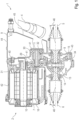
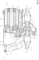
- Fig. 4 shows a schematic, light 3D representation of the drive unit 2 of the drive train 1 in a left-hand drive vehicle in a front view.
- Fig. 5 The drive train 1 in a left-hand drive vehicle is shown in a schematic 3D representation in a front view.
- Fig. 6 shows a schematic 3D representation of the drive train 1 in a left-hand drive vehicle in a rear view.
- Fig. 4 to 6 The same reference numerals are used as for the previous figures. Fig. 4 to 6 In particular, the mechanical connection of the drive unit 2 is evident.
- the drive unit 2 has a drive unit housing 16. On the drive unit housing 16, a plurality of A-side fastening points 18 are formed on a first, A-side 17 of the drive unit housing 16. On the drive unit housing 16, a plurality of B-side fastening points 20 are formed on a second, B-side 19 of the drive unit housing 16, opposite the A-side 17.
- the drive unit housing 16 is fastened by means of at least two of the A-side fastening points 18 to a front unit console 21 and by means of at least two of the B-side fastening points 20 to a rear unit console 22. This situation is shown in the Fig. 5 and 6 shown.
- the power unit housing 16 is attached to the front unit console 21 by means of at least two of the B-side attachment points 20 and to the rear unit console 22 by means of at least two of the A-side attachment points 18.
- the front unit console 21 and the rear unit console 22 are formed on the body 23 of the motor vehicle or connected to the chassis.
- An arrangement of the A-side attachment points 18 relative to one another corresponds to an arrangement of the B-side attachment points 20 relative to one another, wherein the respective arrangement is mirrored on a vertical plane running centrally in a transverse direction through the drive unit housing 16.
- the A-side attachment points 18 and the B-side attachment points 20 thus have the same "pattern.” Due to this identical "pattern," the front unit console 21 and the rear unit console 22 can be universally used in both right-hand drive and left-hand drive vehicles without requiring any structural modifications to the front unit console 21 and the rear unit console 22.
- the front unit console 21 and the rear unit console 22 each have a vertically aligned plate. Horizontal holes are drilled into the front unit console 21 and the rear unit console 22, by means of which the front unit console 21 and the rear unit console 22 are fastened to the drive unit housing 16. Appropriate screws or bolts are used for this purpose. Other fastening methods between the front unit console 21 and the rear unit console 22 and the drive unit housing 16 are conceivable.
- A-side attachment points 18 and five B-side attachment points 20 There are a total of five A-side attachment points 18 and five B-side attachment points 20.
- the connection between the drive unit housing 16 and the front unit console 21 is implemented using all five attachment points on the A-side 17 or the B-side 19.
- the connection between the drive unit housing 2 and the rear unit console 22 is implemented using three of the five attachment points on the A-side 17 or the B-side 19. This takes into account the different load situations on the front unit console 21 and the rear unit console 22.
- the five attachment points are divided into three upper and two lower attachment points, with the rear unit console 22 being connected to the drive unit housing 16 using the two lower attachment points and a central upper attachment point.
- a coolant inlet 24 and a coolant outlet 25 are arranged on the A-side 17 of the drive unit housing 2, and a coolant inlet 26 and a coolant outlet 27 are arranged on the B-side 19 of the drive unit housing 2.
- a cooling fluid can be supplied to the drive unit housing 2 via one of the coolant inlets 24 or 26.
- a cooling fluid can be discharged from the drive unit housing 2 via one of the coolant outlets 25 or 27. Either the coolant inlet 24 and the coolant outlet 25 of the A-side 17, or the coolant inlet 26 and the coolant outlet 27 of the B-side 19 are each closed by a plug and thus rendered inoperative.
- connecting lines and/or connecting hoses are sealingly connected to the coolant inlet 24 or 26 and the coolant outlet 25 or 27.
- Fig. 7 shows a schematic 3D representation of the drive unit 2 of the drive train 1 in a side view in section.
- Fig. 7 the same reference numerals are used as for the previous figures.
- the coolant outlet 25 of the A-side 17 and the coolant outlet 27 of the B-side 19 are connected to each other by means of a through-bore 28, which extends in the direction of travel 12. It is conceivable that the coolant inlet 24 of the A-side 17 and the coolant inlet 26 of the B-side 19 are also connected to each other by a comparable through-bore.
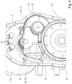
- Fig.8 The transmission unit 8 of the drive train 1 is shown in a schematic 3D representation in a side view. Parts of the drive unit housing 16 have been omitted in order to make the components within the drive unit housing 16 visible. For the same components, Fig. 8 the same reference numerals are used as for the previous figures.
- An input gear 29 and an output gear 30 are arranged or formed on the transmission shaft 11.
- a drive gear 31 is formed or arranged on the drive shaft 10.
- the differential 13 has a differential gear 32.
- the drive gear 31 and the input gear 29 are in mesh with one another, and the output gear 30 and the differential gear 32 are in mesh with one another.
- the drive gear 31, the input gear 29, the output gear 30, and/or the differential gear 32 have, in particular, helical gearing. It would also be conceivable to use straight gearing for at least two of the meshing gears.
- the drive gear 31, the input gear 29, the output gear 30, and the differential gear 32 form a spur gear transmission with two gear stages.
- At least one oil tank 33 is arranged in the drive unit housing 16. At least one oil sump area 34 is formed in the drive unit housing 16, wherein the differential gear 32 is arranged splashing in the oil sump area 34.
- the transmission unit 8 is filled with oil, which collects at least partially in the oil sump area 34 due to gravity, or at least partially repeatedly flows back into the oil sump area 34 during operation of the transmission unit 8.
- Adjacent to the oil tank 33 are A first oil catcher 35 and a second oil catcher 36 are arranged, with a left-hand drive guide region 37 being formed on the first oil catcher 35 and a right-hand drive guide region 38 being formed on the second oil catcher 36.
- oil thrown up from the oil sump region 34 by the differential gear 32 can be fed to the oil tank 33 in a first direction of rotation of the differential gear 32.
- the first direction of rotation of the differential gear 32 occurs when the motor vehicle, which is designed as a left-hand drive vehicle, is traveling forward.
- the right-hand drive guide area 38 By means of the right-hand drive guide area 38, oil thrown up from the oil sump area 34 by the differential gear 32 can be fed to the oil tank 33 in a second direction of rotation of the differential gear 32, opposite to the first direction of rotation.
- the second direction of rotation of the differential gear 32 occurs when the motor vehicle designed as a right-hand drive vehicle is traveling forward.
- the oil tank is thus filled with oil both when used in a left-hand drive vehicle and in a right-hand drive vehicle when the motor vehicle is traveling.
- the left-hand drive guide area 37 and the right-hand drive guide area 38 each have a scraper edge, from which the oil drips or flows from the left-hand drive guide area 37 or the right-hand drive guide area 38 into the oil tank 33 arranged below.
- An oil tank region 39 is formed in the oil tank 33, with the drive gear 31 being arranged in a splashing manner in the oil tank region 39.
- Several contacts 40 are arranged in the drive unit housing 16, with electrical energy being transmittable between the pulse-controlled inverter 9 and the electric machine 7 by means of the contacts 40.
- the electrical energy is transmittable in both directions, so that energy for driving the motor vehicle can be provided by the electric machine 7, with kinetic energy of the motor vehicle also being recuperated by the electric machine 7 and transmitted via the pulse-controlled inverter 9, for example, to a battery of the motor vehicle.
- the contacts 40 can be cooled by means of the oil thrown up from the oil tank region 39 by the drive gear 31. This ensures that the contacts do not exceed a maximum permissible temperature during operation of the motor vehicle.
- the oil tank area 39 is adapted to the shape and size of the drive gear 31, so that it is ensured that during operation of the motor vehicle the drive gear 31 is always immersed far enough into the oil accumulating in the oil tank area 39.
- the gear shaft 11 is mounted in the drive unit housing 16 by means of at least two bearings 41.
- the bearings 41 of the gear shaft 11 have in both directions of rotation of the
- the transmission shaft 11 has such an arrangement and/or dimensioning that the function of the two bearings 41 is ensured for a service life predetermined in the design of the bearings 41 for forward travel of the motor vehicle.
- the direction of rotation of the transmission shaft 11 in a left-hand drive vehicle is opposite when the motor vehicle is traveling forward. Therefore, due to the desired flexibility, it is not sufficient to design one of the two bearings 41 only for reversing the motor vehicle.
- the resulting additional costs due to partially "oversized" bearings 41 are offset by the selection of uniform components and the associated reduction in procurement costs.
- all other components of the transmission unit 8, such as the gearing are designed for a service life predetermined in the design of these components for forward travel of the motor vehicle for both directions of rotation of the transmission shaft 11.
- the drive unit housing 16 is constructed in several parts and has an electric machine sub-housing 42, a transmission sub-housing 43, and a pulse-controlled inverter sub-housing 44.
- the electric machine 7 is arranged in the electric machine sub-housing 42, the transmission unit 8 in the transmission sub-housing 43, and the pulse-controlled inverter 9 in the pulse-controlled inverter sub-housing 44.
- the differential 13 is also arranged in the transmission sub-housing 43.
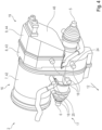
- a bevel 45 is formed on the pulse-controlled inverter sub-housing 44, with an axis of the steering shaft 4 being arranged essentially parallel to the bevel 45 in an area adjacent to the bevel 45. Minor differences in parallelism are tolerable.
- the bevel 45 is formed on an end face of the pulse inverter sub-housing 44 facing away from the gear unit 8.
- the bevel 45 has an angle to a plane running perpendicular to the gear shaft 11, wherein the distance of the end face of the pulse inverter sub-housing 44 facing away from the gear unit 8 to the gear unit 43 is greater in an upper region of the end face of the pulse inverter sub-housing 44 facing away from the gear unit 8 than in the lower region of the end face of the pulse inverter sub-housing 44 facing away from the gear unit 8. This takes into account the fact that the Steering shaft 4 runs from a steering wheel arranged above the steering gear 3 obliquely downwards to a vehicle center.
- the first propeller shaft 5 and the second propeller shaft 6 are each arranged at an angle of deflection 46 to a horizontal plane.
- the deflection angles 46 of the first propeller shaft 5 and the second propeller shaft 6 have the same values.
- the deflection angles 46 of the first propeller shaft 5 and the second propeller shaft 6 are, in particular, less than 7.5°. Due to these small deflection angles 46, the drive train 1 is highly efficient and results in good driving dynamics of the motor vehicle.
- the drive train 1 can be used in a purely electrically driven motor vehicle, wherein only the described electric machine 7 and no further drive is present, wherein only the first propeller shaft 5 and the second propeller shaft 6 and thus a front axle of the motor vehicle can be driven.
- the drive train 1 could also be used in an all-wheel drive vehicle.
- at least one clutch would be arranged in the drive train, with the at least one clutch being able to decouple the first propeller shaft 5 and the second propeller shaft 6 individually or jointly from the electric motor 7.
Landscapes
- Engineering & Computer Science (AREA)
- Mechanical Engineering (AREA)
- General Engineering & Computer Science (AREA)
- Chemical & Material Sciences (AREA)
- Combustion & Propulsion (AREA)
- Transportation (AREA)
- Arrangement Or Mounting Of Propulsion Units For Vehicles (AREA)
- Hybrid Electric Vehicles (AREA)
Claims (15)
- Véhicule automobile comportant une chaîne cinématique (1), dans lequel la chaîne cinématique (1) présente au moins un groupe moteur (2), au moins un mécanisme de direction (3), au moins un arbre de direction (4) et au moins un premier et un second arbre de transmission (5, 6), dans lequel le groupe moteur (2) présente une machine électrique (7), une unité de transmission (8) et un onduleur à impulsions (9), dans lequel la machine électrique (7) et l'onduleur à impulsions (9) sont agencés sur deux côtés opposés de l'unité de transmission (8), dans lequel la machine électrique (7) présente un arbre d'entraînement (10) et l'unité de transmission (8) au moins un arbre de transmission (11), dans lequel l'arbre d'entraînement (10) et l'arbre de transmission (11) s'étendent sensiblement horizontalement et sensiblement perpendiculairement à une direction de déplacement (12) du véhicule automobile, dans lequel le mécanisme de direction (3) est agencé devant le groupe moteur (2) dans la direction de déplacement (12), dans lequel le mécanisme de direction (3) peut être relié de manière fonctionnellement active à un volant de direction du véhicule automobile au moyen de l'arbre de direction (4), dans lequel l'arbre de direction (4) est agencé latéralement à côté du groupe moteur (2), dans lequel l'unité de transmission (8) présente en outre un différentiel (13), dans lequel le différentiel (13) peut être relié de manière active à une première roue avant du véhicule automobile au moyen du premier arbre de transmission (5), et dans lequel le différentiel (13) peut être relié de manière active à une seconde roue avant du véhicule automobile au moyen du second arbre de transmission (6), caractérisé en ce que le différentiel (13) est agencé sensiblement au centre sur un axe longitudinal (14) du véhicule automobile s'étendant au centre du véhicule automobile, dans lequel une longueur du premier arbre de transmission (5) correspond sensiblement à une longueur du second arbre de transmission (6), dans lequel le groupe moteur (2) est conçu de telle sorte que le groupe moteur (2) peut être agencé aussi bien dans un véhicule à conduite à droite que dans un véhicule à conduite à gauche, dans lequel l'agencement du groupe moteur (2) dans le véhicule à conduite à droite est réalisé en étant tourné de 180 ° par rapport à un axe haut vertical (15) par rapport à l'agencement du groupe moteur (2) dans le véhicule à conduite à gauche, dans lequel lorsque le groupe moteur (2) est agencé dans le véhicule à conduite à droite, l'arbre de direction (4) est alors agencé à droite à côté du groupe moteur (2) par rapport à la direction de déplacement (12), et dans lequel lorsque le groupe moteur (2) est agencé dans le véhicule à conduite à gauche, l'arbre de direction (4) est alors agencé à gauche à côté du groupe moteur (2) par rapport à la direction de déplacement (12).
- Véhicule automobile selon la revendication précédente,
caractérisé en ce que la machine électrique (7) est agencée sur un côté de l'unité de transmission (8) opposé à l'arbre de direction (4), aussi bien dans le cas d'un agencement dans le véhicule à conduite à droite que dans le cas d'un agencement dans le véhicule à conduite à gauche. - Véhicule automobile selon l'une des revendications précédentes,
caractérisé en ce que le groupe moteur (2) présente un boîtier (16) de groupe moteur, dans lequel plusieurs points de fixation (18) de côté A sont réalisés sur le boîtier (16) de groupe moteur sur un premier côté A (17) du boîtier (16) de groupe moteur, dans lequel plusieurs points de fixation (20) de côté B sont réalisés sur le boîtier (16) de groupe moteur sur un second côté B (19) du boîtier (16) de groupe moteur opposé au côté A (17), dans lequel le boîtier (16) de groupe moteur peut être fixé au moyen d'au moins deux des points de fixation (18) de côté A à une console d'unité frontale (21) avant et au moyen d'au moins deux des points de fixation (20) de côté B à une console d'unité de queue (22) arrière, ou dans lequel le boîtier (16) de groupe moteur peut être fixé au moyen d'au moins deux des points de fixation (20) de côté B à la console d'unité frontale (21) avant et au moyen d'au moins deux des points de fixation (18) de côté A à la console d'unité de queue (22) arrière, et dans lequel la console d'unité frontale (21) et la console d'unité de queue (22) sont réalisées sur un châssis (23) du véhicule automobile ou sont reliées à la carrosserie (23). - Véhicule automobile selon la revendication précédente, caractérisé en ce qu'un agencement des points de fixation (18) de côté A les uns par rapport aux autres correspond à un agencement des points de fixation (20) de côté B les uns par rapport aux autres, dans lequel l'agencement des points de fixation (18) de côté A par rapport aux points de fixation (20) de côté B est en particulier reflété sur un plan vertical passant au centre dans une direction transversale à travers le boîtier (16) de groupe moteur.
- Véhicule automobile selon l'une des revendications précédentes 3 ou 4,
caractérisé en ce que cinq points de fixation (18) de côté A et cinq points de fixation (20) de côté B sont présents et/ou réalisés. - Véhicule automobile selon l'une des revendications précédentes,
caractérisé en ce que respectivement une arrivée (24) de fluide de refroidissement et une évacuation (25) de fluide de refroidissement sont agencées sur le côté A (17) et respectivement une arrivée (26) de fluide de refroidissement et une évacuation (27) de fluide de refroidissement sont agencées sur le côté B (19) du boîtier (16) de groupe moteur, dans lequel un fluide de refroidissement peut être amené au boîtier (16) de groupe moteur au moyen d'une des arrivées (24, 26) de fluide de refroidissement, dans lequel un fluide de refroidissement peut être évacué du boîtier (16) de groupe moteur au moyen d'une des évacuations (25, 27) de fluide de refroidissement, dans lequel soit l'arrivée (24) de fluide de refroidissement et l'évacuation (24) de fluide de refroidissement du côté A (17), soit l'arrivée (25) de fluide de refroidissement et l'évacuation (25) de fluide de refroidissement du côté B (19) sont fermées au moyen d'un bouchon respectif et sont ainsi mises hors fonction. - Véhicule automobile selon la revendication 6, caractérisé en ce que l'arrivée (24) de liquide de refroidissement du côté A (17) et l'arrivée (24) de liquide de refroidissement du côté B (19) et/ou l'évacuation (25) de liquide de refroidissement du côté A (17) et l'évacuation (27) de liquide de refroidissement du côté B (19) sont reliées entre elles au moyen d'un alésage (28) traversant, dans lequel ledit alésage (28) s'étend dans la direction de déplacement (12).
- Véhicule automobile selon l'une des revendications précédentes,
caractérisé en ce qu'une roue dentée d'entrée (29) et une roue dentée de sortie (30) sont agencées ou réalisées sur l'arbre de transmission (11), dans lequel une roue dentée d'entraînement (31) est réalisée ou agencée sur l'arbre d'entraînement (10), dans lequel le différentiel (13) présente une roue dentée de différentiel (32), dans lequel la roue dentée d'entraînement (31) et la roue dentée d'entrée (29) sont en prise l'une avec l'autre, dans lequel la roue dentée de sortie (30) et la roue dentée de différentiel (32) sont en prise l'une avec l'autre, en particulier dans lequel la roue dentée d'entraînement (31), la roue dentée d'entrée (29), la roue dentée de sortie (30) et/ou la roue dentée de différentiel (32) présentent une denture oblique. - Véhicule automobile selon la revendication 8, caractérisé en ce qu'au moins un réservoir d'huile (33) est agencé dans le boîtier (16) de groupe moteur, dans lequel au moins une zone de carter d'huile (34) est réalisée dans le boîtier (16) de groupe moteur, dans lequel la roue dentée de différentiel (32) est agencée de manière à patauger dans la zone de carter d'huile (34), dans lequel un premier collecteur d'huile (35) et un second collecteur d'huile (36) sont agencés de manière adjacente au réservoir d'huile (33), dans lequel une zone de guidage de conduite à gauche (37) est réalisée sur le premier collecteur d'huile (35) et une zone de guidage de conduite à droite (38) est réalisée sur le second collecteur d'huile (36), dans lequel l'huile projetée par la roue dentée de différentiel (32) hors de la zone de carter d'huile (34) peut être amenée au réservoir d'huile (33) dans un premier sens de rotation de la roue dentée de différentiel (32) au moyen de la zone de guidage de conduite à gauche (37), et dans lequel l'huile projetée par la roue dentée de différentiel (32) hors de la zone de carter d'huile (34) au moyen de la zone de guidage de conduite à droite (38) peut être amenée au réservoir d'huile (33) dans un second sens de rotation de la roue dentée de différentiel (32) opposé au premier sens de rotation.
- Véhicule automobile selon la revendication 9, caractérisé en ce qu'une zone de réservoir d'huile (39) est agencée et/ou réalisée dans le réservoir d'huile (33), dans lequel la roue dentée d'entraînement (31) est agencée de manière à patauger dans la zone de réservoir d'huile (39), dans lequel plusieurs contacts (40) sont agencés dans le boîtier (16) de groupe moteur, dans lequel l'énergie électrique peut être transmise entre l'onduleur à impulsions (9) et la machine électrique (7) au moyen des contacts (40), et dans lequel les contacts (40) peuvent être refroidis au moyen de l'huile projetée par la roue dentée d'entraînement (31) hors de la zone de réservoir d'huile (39).
- Véhicule automobile selon l'une des revendications précédentes,
caractérisé en ce que l'arbre de transmission (11) est monté dans le boîtier (16) de groupe moteur au moyen d'au moins deux paliers (41), dans lequel les paliers (41) de l'arbre de transmission (11) présentent, dans les deux sens de rotation de l'arbre de transmission (11), un agencement et/ou un dimensionnement tels que le fonctionnement des deux paliers (41) est assuré pour une durée de vie prédéterminée dans la conception des paliers (41) pour une marche avant du véhicule automobile. - Véhicule automobile selon l'une des revendications précédentes 3 à 11,
caractérisé en ce que le boîtier (16) de groupe moteur est conçu en plusieurs parties et présente un boîtier partiel (42) de machine électrique, un boîtier partiel (43) de transmission et un boîtier partiel (44) d'onduleur à impulsions, dans lequel la machine électrique (7) est agencée dans le boîtier partiel (42) de machine électrique, l'unité de transmission (8) dans le boîtier partiel (43) de transmission et l'onduleur à impulsions (9) dans le boîtier partiel (44) d'onduleur à impulsions, dans lequel un chanfrein (45) est réalisé sur le boîtier partiel (44) d'onduleur à impulsions, dans lequel un axe de l'arbre de direction (4) est agencé dans une zone adjacente au chanfrein (45), en particulier sensiblement parallèle au chanfrein (45). - Véhicule automobile selon la revendication 12, caractérisé en ce que le chanfrein (45) est réalisé sur une face frontale du boîtier partiel (44) d'onduleur à impulsions, opposée à l'unité de transmission (8).
- Véhicule automobile selon l'une des revendications précédentes 12 ou 13, caractérisé en ce que le chanfrein (45) présente un angle par rapport à un plan perpendiculaire à l'arbre de transmission (11), dans lequel la distance entre la face frontale du boîtier partiel (44) d'onduleur à impulsions, opposée à l'unité de transmission (8), et le boîtier partiel (43) de transmission est supérieure dans une zone supérieure de la face frontale de boîtier partiel (44) d'onduleur à impulsions, opposée à l'unité de transmission (8), que dans la zone inférieure de la face frontale du boîtier partiel (44) d'onduleur à impulsions, opposée à l'unité de transmission (8).
- Véhicule automobile selon l'une des revendications précédentes,
caractérisé en ce que le premier arbre de transmission (5) et le second arbre de transmission (6) sont agencés respectivement selon un angle de courbure (46) par rapport à un plan horizontal, dans lequel les angles de courbure (46) du premier arbre de transmission (5) et du second arbre de transmission (6) présentent des valeurs sensiblement égales, en particulier dans lequel les angles de courbure (46) du premier arbre de transmission (5) et du second arbre de transmission (6) sont inférieurs à 7,5 °.
Applications Claiming Priority (1)
| Application Number | Priority Date | Filing Date | Title |
|---|---|---|---|
| DE102021201547.6A DE102021201547A1 (de) | 2021-02-18 | 2021-02-18 | Antriebsstrang für ein Kraftfahrzeug |
Publications (2)
| Publication Number | Publication Date |
|---|---|
| EP4046845A1 EP4046845A1 (fr) | 2022-08-24 |
| EP4046845B1 true EP4046845B1 (fr) | 2025-05-14 |
Family
ID=80225968
Family Applications (1)
| Application Number | Title | Priority Date | Filing Date |
|---|---|---|---|
| EP22154705.2A Active EP4046845B1 (fr) | 2021-02-18 | 2022-02-02 | Groupe motopropulseur pour véhicule |
Country Status (3)
| Country | Link |
|---|---|
| EP (1) | EP4046845B1 (fr) |
| CN (1) | CN115009008B (fr) |
| DE (1) | DE102021201547A1 (fr) |
Families Citing this family (1)
| Publication number | Priority date | Publication date | Assignee | Title |
|---|---|---|---|---|
| DE112022007787T5 (de) * | 2022-09-20 | 2025-07-03 | Gkn Automotive Limited | Gehäuseanordnung und Elektroantrieb mit einer solchen Gehäuseanordnung |
Family Cites Families (14)
| Publication number | Priority date | Publication date | Assignee | Title |
|---|---|---|---|---|
| US9030063B2 (en) | 2010-12-17 | 2015-05-12 | Tesla Motors, Inc. | Thermal management system for use with an integrated motor assembly |
| KR101302262B1 (ko) * | 2011-03-30 | 2013-09-02 | 가부시끼 가이샤 구보다 | 작업차 |
| DE102012100865B4 (de) * | 2012-02-02 | 2016-10-27 | Gkn Driveline International Gmbh | Antriebsanordnung mit elektrischer Maschine und Kraftfahrzeug mit einer solchen Antriebsanordnung |
| US8585859B2 (en) * | 2012-02-14 | 2013-11-19 | GM Global Technology Operations LLC | Attachment member with integral adhesive channel and method |
| DE102012025371B4 (de) * | 2012-12-28 | 2016-09-01 | Volkswagen Aktiengesellschaft | Kraftfahrzeug |
| DE102013204784B4 (de) | 2013-03-19 | 2018-01-11 | Robert Bosch Gmbh | Elektrische Fahrzeugachsenvorrichtung |
| WO2016184607A1 (fr) * | 2015-05-18 | 2016-11-24 | Bayerische Motoren Werke Aktiengesellschaft | Véhicule automobile muni d'un support d'essieu |
| CN105216598B (zh) | 2015-09-28 | 2018-10-16 | 上海蔚来汽车有限公司 | 一种汽车用的电驱动系统及使用了该电驱动系统的汽车 |
| DE102016212818A1 (de) * | 2016-07-13 | 2018-01-18 | Volkswagen Aktiengesellschaft | Lenkung für Fahrzeuge mit Hochübersetzungsgetriebe, insbesondere für Nutzkraftfahrzeuge |
| US10352345B2 (en) * | 2016-12-05 | 2019-07-16 | The Boeing Company | Adhesive-bonded attachment device |
| DE102017201299A1 (de) | 2017-01-27 | 2018-08-02 | Bayerische Motoren Werke Aktiengesellschaft | Brennstoffzellenfahrzeug |
| CN109591514A (zh) * | 2017-09-30 | 2019-04-09 | 比亚迪股份有限公司 | 集成式转向驱动桥总成和车辆 |
| CN111183054A (zh) * | 2017-10-24 | 2020-05-19 | 日产自动车株式会社 | 四轮驱动车的动力传递装置 |
| US11482907B2 (en) | 2017-12-15 | 2022-10-25 | Rivian Ip Holdings, Llc | Electric vehicle drive units |
-
2021
- 2021-02-18 DE DE102021201547.6A patent/DE102021201547A1/de active Pending
-
2022
- 2022-02-02 EP EP22154705.2A patent/EP4046845B1/fr active Active
- 2022-02-18 CN CN202210149863.XA patent/CN115009008B/zh active Active
Also Published As
| Publication number | Publication date |
|---|---|
| DE102021201547A1 (de) | 2022-08-18 |
| CN115009008B (zh) | 2025-08-15 |
| CN115009008A (zh) | 2022-09-06 |
| EP4046845A1 (fr) | 2022-08-24 |
Similar Documents
| Publication | Publication Date | Title |
|---|---|---|
| DE19812677B4 (de) | Verteilergetriebe für ein vierradgetriebenes Kraftfahrzeug | |
| DE102004058025A1 (de) | Hybridantriebseinheit sowie damit ausgestattetes Fahrzeug | |
| DE202019103781U1 (de) | Twin-Getriebe mit einer Doppel-Eingangswelle | |
| DE10162337B4 (de) | Längs eingebauter Antriebsstrang | |
| WO2018073378A1 (fr) | Ensemble d'entraînement pour véhicule automobile, muni d'un moteur électrique | |
| DE102005019489A1 (de) | Allradangetriebenes Kraftfahrzeug | |
| DE102017205721A1 (de) | Getriebeeinheit für ein Kraftfahrzeug | |
| DE4107286A1 (de) | Aufbau eines antriebsstranges eines kraftfahrzeuges | |
| DE102020118194A1 (de) | Twin-Getriebe mit einer Doppel-Eingangswelle | |
| EP4046845B1 (fr) | Groupe motopropulseur pour véhicule | |
| DE102022213923B4 (de) | Getriebe für ein Fahrzeug sowie Antriebsstrang mit einem solchen Getriebe | |
| EP4396013B1 (fr) | Ensemble chaîne de puissance d'un engin de travail et engin de travail | |
| DE112013004022T5 (de) | Anordnung zum Schmieren eines Differentialgetriebes für einen Tandembetrieb | |
| DE102021132153B3 (de) | Antriebssystem und Antriebsanordnung | |
| EP4286192B1 (fr) | Transmission hybride pour véhicule | |
| DE102009051124B4 (de) | Antriebssystem für ein Elektroradfahrzeug | |
| EP3434550B1 (fr) | Système d'entrainement | |
| EP2179881A1 (fr) | Véhicule automobile doté d'un entraînement toute roue | |
| DE202017102027U1 (de) | Getriebeeinheit für ein Kraftfahrzeug | |
| EP3170689A1 (fr) | Véhicule hybride | |
| EP1620287B1 (fr) | Ensemble moteur pour vehicules | |
| DE102021200280A1 (de) | Antriebsvorrichtung für ein elektrisch angetriebenes Fahrzeug | |
| DE102022213159B3 (de) | Schiffsgetriebe mit einem Nebenantrieb | |
| DE102024200485B3 (de) | Getriebeanordnung sowie Antriebsstrang mit einer solchen Getriebeanordnung | |
| WO2021018344A1 (fr) | Unité d'entraînement électrique, module hybride et ensemble d'entraînement pour véhicule automobile |
Legal Events
| Date | Code | Title | Description |
|---|---|---|---|
| PUAI | Public reference made under article 153(3) epc to a published international application that has entered the european phase |
Free format text: ORIGINAL CODE: 0009012 |
|
| STAA | Information on the status of an ep patent application or granted ep patent |
Free format text: STATUS: THE APPLICATION HAS BEEN PUBLISHED |
|
| AK | Designated contracting states |
Kind code of ref document: A1 Designated state(s): AL AT BE BG CH CY CZ DE DK EE ES FI FR GB GR HR HU IE IS IT LI LT LU LV MC MK MT NL NO PL PT RO RS SE SI SK SM TR |
|
| STAA | Information on the status of an ep patent application or granted ep patent |
Free format text: STATUS: REQUEST FOR EXAMINATION WAS MADE |
|
| 17P | Request for examination filed |
Effective date: 20230224 |
|
| RBV | Designated contracting states (corrected) |
Designated state(s): AL AT BE BG CH CY CZ DE DK EE ES FI FR GB GR HR HU IE IS IT LI LT LU LV MC MK MT NL NO PL PT RO RS SE SI SK SM TR |
|
| GRAP | Despatch of communication of intention to grant a patent |
Free format text: ORIGINAL CODE: EPIDOSNIGR1 |
|
| STAA | Information on the status of an ep patent application or granted ep patent |
Free format text: STATUS: GRANT OF PATENT IS INTENDED |
|
| RIC1 | Information provided on ipc code assigned before grant |
Ipc: B62D 7/00 20060101ALI20250213BHEP Ipc: B60K 1/00 20060101ALI20250213BHEP Ipc: B60K 17/30 20060101ALI20250213BHEP Ipc: B60K 17/16 20060101AFI20250213BHEP |
|
| INTG | Intention to grant announced |
Effective date: 20250304 |
|
| GRAS | Grant fee paid |
Free format text: ORIGINAL CODE: EPIDOSNIGR3 |
|
| GRAA | (expected) grant |
Free format text: ORIGINAL CODE: 0009210 |
|
| STAA | Information on the status of an ep patent application or granted ep patent |
Free format text: STATUS: THE PATENT HAS BEEN GRANTED |
|
| P01 | Opt-out of the competence of the unified patent court (upc) registered |
Free format text: CASE NUMBER: APP_10991/2025 Effective date: 20250306 |
|
| AK | Designated contracting states |
Kind code of ref document: B1 Designated state(s): AL AT BE BG CH CY CZ DE DK EE ES FI FR GB GR HR HU IE IS IT LI LT LU LV MC MK MT NL NO PL PT RO RS SE SI SK SM TR |
|
| REG | Reference to a national code |
Ref country code: GB Ref legal event code: FG4D Free format text: NOT ENGLISH |
|
| REG | Reference to a national code |
Ref country code: CH Ref legal event code: EP |
|
| REG | Reference to a national code |
Ref country code: DE Ref legal event code: R096 Ref document number: 502022003918 Country of ref document: DE |
|
| REG | Reference to a national code |
Ref country code: IE Ref legal event code: FG4D Free format text: LANGUAGE OF EP DOCUMENT: GERMAN |
|
| REG | Reference to a national code |
Ref country code: NL Ref legal event code: MP Effective date: 20250514 |
|
| PG25 | Lapsed in a contracting state [announced via postgrant information from national office to epo] |
Ref country code: PT Free format text: LAPSE BECAUSE OF FAILURE TO SUBMIT A TRANSLATION OF THE DESCRIPTION OR TO PAY THE FEE WITHIN THE PRESCRIBED TIME-LIMIT Effective date: 20250915 Ref country code: ES Free format text: LAPSE BECAUSE OF FAILURE TO SUBMIT A TRANSLATION OF THE DESCRIPTION OR TO PAY THE FEE WITHIN THE PRESCRIBED TIME-LIMIT Effective date: 20250514 Ref country code: FI Free format text: LAPSE BECAUSE OF FAILURE TO SUBMIT A TRANSLATION OF THE DESCRIPTION OR TO PAY THE FEE WITHIN THE PRESCRIBED TIME-LIMIT Effective date: 20250514 |
|
| REG | Reference to a national code |
Ref country code: LT Ref legal event code: MG9D |
|
| PG25 | Lapsed in a contracting state [announced via postgrant information from national office to epo] |
Ref country code: GR Free format text: LAPSE BECAUSE OF FAILURE TO SUBMIT A TRANSLATION OF THE DESCRIPTION OR TO PAY THE FEE WITHIN THE PRESCRIBED TIME-LIMIT Effective date: 20250815 Ref country code: NO Free format text: LAPSE BECAUSE OF FAILURE TO SUBMIT A TRANSLATION OF THE DESCRIPTION OR TO PAY THE FEE WITHIN THE PRESCRIBED TIME-LIMIT Effective date: 20250814 |
|
| PG25 | Lapsed in a contracting state [announced via postgrant information from national office to epo] |
Ref country code: PL Free format text: LAPSE BECAUSE OF FAILURE TO SUBMIT A TRANSLATION OF THE DESCRIPTION OR TO PAY THE FEE WITHIN THE PRESCRIBED TIME-LIMIT Effective date: 20250514 Ref country code: NL Free format text: LAPSE BECAUSE OF FAILURE TO SUBMIT A TRANSLATION OF THE DESCRIPTION OR TO PAY THE FEE WITHIN THE PRESCRIBED TIME-LIMIT Effective date: 20250514 |
|
| PG25 | Lapsed in a contracting state [announced via postgrant information from national office to epo] |
Ref country code: BG Free format text: LAPSE BECAUSE OF FAILURE TO SUBMIT A TRANSLATION OF THE DESCRIPTION OR TO PAY THE FEE WITHIN THE PRESCRIBED TIME-LIMIT Effective date: 20250514 |
|
| PG25 | Lapsed in a contracting state [announced via postgrant information from national office to epo] |
Ref country code: HR Free format text: LAPSE BECAUSE OF FAILURE TO SUBMIT A TRANSLATION OF THE DESCRIPTION OR TO PAY THE FEE WITHIN THE PRESCRIBED TIME-LIMIT Effective date: 20250514 |
|
| PG25 | Lapsed in a contracting state [announced via postgrant information from national office to epo] |
Ref country code: RS Free format text: LAPSE BECAUSE OF FAILURE TO SUBMIT A TRANSLATION OF THE DESCRIPTION OR TO PAY THE FEE WITHIN THE PRESCRIBED TIME-LIMIT Effective date: 20250814 |
|
| PG25 | Lapsed in a contracting state [announced via postgrant information from national office to epo] |
Ref country code: IS Free format text: LAPSE BECAUSE OF FAILURE TO SUBMIT A TRANSLATION OF THE DESCRIPTION OR TO PAY THE FEE WITHIN THE PRESCRIBED TIME-LIMIT Effective date: 20250914 |
|
| PG25 | Lapsed in a contracting state [announced via postgrant information from national office to epo] |
Ref country code: LV Free format text: LAPSE BECAUSE OF FAILURE TO SUBMIT A TRANSLATION OF THE DESCRIPTION OR TO PAY THE FEE WITHIN THE PRESCRIBED TIME-LIMIT Effective date: 20250514 |
|
| PG25 | Lapsed in a contracting state [announced via postgrant information from national office to epo] |
Ref country code: DK Free format text: LAPSE BECAUSE OF FAILURE TO SUBMIT A TRANSLATION OF THE DESCRIPTION OR TO PAY THE FEE WITHIN THE PRESCRIBED TIME-LIMIT Effective date: 20250514 Ref country code: SM Free format text: LAPSE BECAUSE OF FAILURE TO SUBMIT A TRANSLATION OF THE DESCRIPTION OR TO PAY THE FEE WITHIN THE PRESCRIBED TIME-LIMIT Effective date: 20250514 |
|
| PG25 | Lapsed in a contracting state [announced via postgrant information from national office to epo] |
Ref country code: CZ Free format text: LAPSE BECAUSE OF FAILURE TO SUBMIT A TRANSLATION OF THE DESCRIPTION OR TO PAY THE FEE WITHIN THE PRESCRIBED TIME-LIMIT Effective date: 20250514 |
|
| PG25 | Lapsed in a contracting state [announced via postgrant information from national office to epo] |
Ref country code: EE Free format text: LAPSE BECAUSE OF FAILURE TO SUBMIT A TRANSLATION OF THE DESCRIPTION OR TO PAY THE FEE WITHIN THE PRESCRIBED TIME-LIMIT Effective date: 20250514 |
|
| PG25 | Lapsed in a contracting state [announced via postgrant information from national office to epo] |
Ref country code: SK Free format text: LAPSE BECAUSE OF FAILURE TO SUBMIT A TRANSLATION OF THE DESCRIPTION OR TO PAY THE FEE WITHIN THE PRESCRIBED TIME-LIMIT Effective date: 20250514 |
|
| PG25 | Lapsed in a contracting state [announced via postgrant information from national office to epo] |
Ref country code: IT Free format text: LAPSE BECAUSE OF FAILURE TO SUBMIT A TRANSLATION OF THE DESCRIPTION OR TO PAY THE FEE WITHIN THE PRESCRIBED TIME-LIMIT Effective date: 20250514 |
|
| REG | Reference to a national code |
Ref country code: DE Ref legal event code: R097 Ref document number: 502022003918 Country of ref document: DE |
|
| PLBE | No opposition filed within time limit |
Free format text: ORIGINAL CODE: 0009261 |
|
| STAA | Information on the status of an ep patent application or granted ep patent |
Free format text: STATUS: NO OPPOSITION FILED WITHIN TIME LIMIT |
|
| REG | Reference to a national code |
Ref country code: CH Ref legal event code: L10 Free format text: ST27 STATUS EVENT CODE: U-0-0-L10-L00 (AS PROVIDED BY THE NATIONAL OFFICE) Effective date: 20260325 |
|
| PGFP | Annual fee paid to national office [announced via postgrant information from national office to epo] |
Ref country code: GB Payment date: 20260223 Year of fee payment: 5 |
|
| PGFP | Annual fee paid to national office [announced via postgrant information from national office to epo] |
Ref country code: DE Payment date: 20260228 Year of fee payment: 5 |
|
| PGFP | Annual fee paid to national office [announced via postgrant information from national office to epo] |
Ref country code: AT Payment date: 20260301 Year of fee payment: 5 |
|
| PGFP | Annual fee paid to national office [announced via postgrant information from national office to epo] |
Ref country code: FR Payment date: 20260227 Year of fee payment: 5 |
|
| 26N | No opposition filed |
Effective date: 20260217 |