EP4046845B1 - Drive train for a motor vehicle - Google Patents
Drive train for a motor vehicle Download PDFInfo
- Publication number
- EP4046845B1 EP4046845B1 EP22154705.2A EP22154705A EP4046845B1 EP 4046845 B1 EP4046845 B1 EP 4046845B1 EP 22154705 A EP22154705 A EP 22154705A EP 4046845 B1 EP4046845 B1 EP 4046845B1
- Authority
- EP
- European Patent Office
- Prior art keywords
- drive
- drive unit
- housing
- gear
- motor vehicle
- Prior art date
- Legal status (The legal status is an assumption and is not a legal conclusion. Google has not performed a legal analysis and makes no representation as to the accuracy of the status listed.)
- Active
Links
Images


Classifications
-
- B—PERFORMING OPERATIONS; TRANSPORTING
- B60—VEHICLES IN GENERAL
- B60K—ARRANGEMENT OR MOUNTING OF PROPULSION UNITS OR OF TRANSMISSIONS IN VEHICLES; ARRANGEMENT OR MOUNTING OF PLURAL DIVERSE PRIME-MOVERS IN VEHICLES; AUXILIARY DRIVES FOR VEHICLES; INSTRUMENTATION OR DASHBOARDS FOR VEHICLES; ARRANGEMENTS IN CONNECTION WITH COOLING, AIR INTAKE, GAS EXHAUST OR FUEL SUPPLY OF PROPULSION UNITS IN VEHICLES
- B60K17/00—Arrangement or mounting of transmissions in vehicles
- B60K17/04—Arrangement or mounting of transmissions in vehicles characterised by arrangement, location or kind of gearing
- B60K17/16—Arrangement or mounting of transmissions in vehicles characterised by arrangement, location or kind of gearing of differential gearing
- B60K17/165—Arrangement or mounting of transmissions in vehicles characterised by arrangement, location or kind of gearing of differential gearing provided between independent half axles
-
- B—PERFORMING OPERATIONS; TRANSPORTING
- B60—VEHICLES IN GENERAL
- B60K—ARRANGEMENT OR MOUNTING OF PROPULSION UNITS OR OF TRANSMISSIONS IN VEHICLES; ARRANGEMENT OR MOUNTING OF PLURAL DIVERSE PRIME-MOVERS IN VEHICLES; AUXILIARY DRIVES FOR VEHICLES; INSTRUMENTATION OR DASHBOARDS FOR VEHICLES; ARRANGEMENTS IN CONNECTION WITH COOLING, AIR INTAKE, GAS EXHAUST OR FUEL SUPPLY OF PROPULSION UNITS IN VEHICLES
- B60K1/00—Arrangement or mounting of electrical propulsion units
-
- B—PERFORMING OPERATIONS; TRANSPORTING
- B60—VEHICLES IN GENERAL
- B60K—ARRANGEMENT OR MOUNTING OF PROPULSION UNITS OR OF TRANSMISSIONS IN VEHICLES; ARRANGEMENT OR MOUNTING OF PLURAL DIVERSE PRIME-MOVERS IN VEHICLES; AUXILIARY DRIVES FOR VEHICLES; INSTRUMENTATION OR DASHBOARDS FOR VEHICLES; ARRANGEMENTS IN CONNECTION WITH COOLING, AIR INTAKE, GAS EXHAUST OR FUEL SUPPLY OF PROPULSION UNITS IN VEHICLES
- B60K17/00—Arrangement or mounting of transmissions in vehicles
- B60K17/04—Arrangement or mounting of transmissions in vehicles characterised by arrangement, location or kind of gearing
- B60K17/06—Arrangement or mounting of transmissions in vehicles characterised by arrangement, location or kind of gearing of change-speed gearing
- B60K17/08—Arrangement or mounting of transmissions in vehicles characterised by arrangement, location or kind of gearing of change-speed gearing of mechanical type
-
- B—PERFORMING OPERATIONS; TRANSPORTING
- B60—VEHICLES IN GENERAL
- B60K—ARRANGEMENT OR MOUNTING OF PROPULSION UNITS OR OF TRANSMISSIONS IN VEHICLES; ARRANGEMENT OR MOUNTING OF PLURAL DIVERSE PRIME-MOVERS IN VEHICLES; AUXILIARY DRIVES FOR VEHICLES; INSTRUMENTATION OR DASHBOARDS FOR VEHICLES; ARRANGEMENTS IN CONNECTION WITH COOLING, AIR INTAKE, GAS EXHAUST OR FUEL SUPPLY OF PROPULSION UNITS IN VEHICLES
- B60K17/00—Arrangement or mounting of transmissions in vehicles
- B60K17/30—Arrangement or mounting of transmissions in vehicles the ultimate propulsive elements, e.g. ground wheels, being steerable
-
- B—PERFORMING OPERATIONS; TRANSPORTING
- B60—VEHICLES IN GENERAL
- B60K—ARRANGEMENT OR MOUNTING OF PROPULSION UNITS OR OF TRANSMISSIONS IN VEHICLES; ARRANGEMENT OR MOUNTING OF PLURAL DIVERSE PRIME-MOVERS IN VEHICLES; AUXILIARY DRIVES FOR VEHICLES; INSTRUMENTATION OR DASHBOARDS FOR VEHICLES; ARRANGEMENTS IN CONNECTION WITH COOLING, AIR INTAKE, GAS EXHAUST OR FUEL SUPPLY OF PROPULSION UNITS IN VEHICLES
- B60K6/00—Arrangement or mounting of plural diverse prime-movers for mutual or common propulsion, e.g. hybrid propulsion systems comprising electric motors and internal combustion engines
- B60K6/20—Arrangement or mounting of plural diverse prime-movers for mutual or common propulsion, e.g. hybrid propulsion systems comprising electric motors and internal combustion engines the prime-movers consisting of electric motors and internal combustion engines, e.g. HEVs
- B60K6/22—Arrangement or mounting of plural diverse prime-movers for mutual or common propulsion, e.g. hybrid propulsion systems comprising electric motors and internal combustion engines the prime-movers consisting of electric motors and internal combustion engines, e.g. HEVs characterised by apparatus, components or means specially adapted for HEVs
- B60K6/40—Arrangement or mounting of plural diverse prime-movers for mutual or common propulsion, e.g. hybrid propulsion systems comprising electric motors and internal combustion engines the prime-movers consisting of electric motors and internal combustion engines, e.g. HEVs characterised by apparatus, components or means specially adapted for HEVs characterised by the assembly or relative disposition of components
- B60K6/405—Housings
-
- F—MECHANICAL ENGINEERING; LIGHTING; HEATING; WEAPONS; BLASTING
- F16—ENGINEERING ELEMENTS AND UNITS; GENERAL MEASURES FOR PRODUCING AND MAINTAINING EFFECTIVE FUNCTIONING OF MACHINES OR INSTALLATIONS; THERMAL INSULATION IN GENERAL
- F16H—GEARING
- F16H48/00—Differential gearings
- F16H48/06—Differential gearings with gears having orbital motion
- F16H48/10—Differential gearings with gears having orbital motion with orbital spur gears
-
- F—MECHANICAL ENGINEERING; LIGHTING; HEATING; WEAPONS; BLASTING
- F16—ENGINEERING ELEMENTS AND UNITS; GENERAL MEASURES FOR PRODUCING AND MAINTAINING EFFECTIVE FUNCTIONING OF MACHINES OR INSTALLATIONS; THERMAL INSULATION IN GENERAL
- F16H—GEARING
- F16H57/00—General details of gearing
- F16H57/04—Features relating to lubrication or cooling or heating
- F16H57/042—Guidance of lubricant
-
- F—MECHANICAL ENGINEERING; LIGHTING; HEATING; WEAPONS; BLASTING
- F16—ENGINEERING ELEMENTS AND UNITS; GENERAL MEASURES FOR PRODUCING AND MAINTAINING EFFECTIVE FUNCTIONING OF MACHINES OR INSTALLATIONS; THERMAL INSULATION IN GENERAL
- F16H—GEARING
- F16H57/00—General details of gearing
- F16H57/04—Features relating to lubrication or cooling or heating
- F16H57/045—Lubricant storage reservoirs, e.g. reservoirs in addition to a gear sump for collecting lubricant in the upper part of a gear case
- F16H57/0452—Oil pans
-
- F—MECHANICAL ENGINEERING; LIGHTING; HEATING; WEAPONS; BLASTING
- F16—ENGINEERING ELEMENTS AND UNITS; GENERAL MEASURES FOR PRODUCING AND MAINTAINING EFFECTIVE FUNCTIONING OF MACHINES OR INSTALLATIONS; THERMAL INSULATION IN GENERAL
- F16H—GEARING
- F16H57/00—General details of gearing
- F16H57/04—Features relating to lubrication or cooling or heating
- F16H57/048—Type of gearings to be lubricated, cooled or heated
- F16H57/0493—Gearings with spur or bevel gears
- F16H57/0495—Gearings with spur or bevel gears with fixed gear ratio
-
- B—PERFORMING OPERATIONS; TRANSPORTING
- B60—VEHICLES IN GENERAL
- B60K—ARRANGEMENT OR MOUNTING OF PROPULSION UNITS OR OF TRANSMISSIONS IN VEHICLES; ARRANGEMENT OR MOUNTING OF PLURAL DIVERSE PRIME-MOVERS IN VEHICLES; AUXILIARY DRIVES FOR VEHICLES; INSTRUMENTATION OR DASHBOARDS FOR VEHICLES; ARRANGEMENTS IN CONNECTION WITH COOLING, AIR INTAKE, GAS EXHAUST OR FUEL SUPPLY OF PROPULSION UNITS IN VEHICLES
- B60K1/00—Arrangement or mounting of electrical propulsion units
- B60K2001/001—Arrangement or mounting of electrical propulsion units one motor mounted on a propulsion axle for rotating right and left wheels of this axle
-
- B—PERFORMING OPERATIONS; TRANSPORTING
- B62—LAND VEHICLES FOR TRAVELLING OTHERWISE THAN ON RAILS
- B62D—MOTOR VEHICLES; TRAILERS
- B62D3/00—Steering gears
- B62D3/02—Steering gears mechanical
- B62D3/12—Steering gears mechanical of rack-and-pinion type
Definitions
- the invention relates to a motor vehicle with a drive train according to the features of the preamble of patent claim 1.
- Drivetrains for motor vehicles comprising a drive unit, a steering gear, a steering shaft, and a first and a second cardan shaft are known in the prior art.
- the corresponding drive unit comprises an electric motor, a transmission unit, and a pulse-controlled inverter, wherein the electric motor and the pulse-controlled inverter are arranged on two opposite sides of the transmission unit.
- a drive shaft of the electric motor and a transmission shaft of the transmission unit extend essentially horizontally and essentially perpendicular to a direction of travel of the motor vehicle.
- the steering gear is arranged in front of the drive unit in the direction of travel (forward direction of travel). This means that, viewed from front to rear of the motor vehicle, the steering gear is arranged first, followed by the drive unit.
- the steering gear can be functionally connected to a steering wheel of the motor vehicle. Therefore, the steering shaft is arranged laterally next to the drive unit.
- the transmission unit further comprises a differential, wherein the differential can be effectively connected to a first front wheel of the motor vehicle by means of the first cardan shaft.
- the differential can also be effectively connected to a second front wheel of the motor vehicle by means of the second drive shaft.
- the US 2019 / 0222095 A1 shows a modular drive system.
- a first electric machine is coupled to a differential via a first transmission.
- the first electric machine can be coupled to a second electric machine to form a dual drive unit.
- the operation of the first electric machine is controlled by a first pulse-controlled inverter.
- the first pulse-controlled inverter is aligned with a first motor axis and arranged on the side of the first transmission opposite the first electric machine.
- the operation of the second electric machine is controlled by a second pulse-controlled inverter.
- the second pulse-controlled inverter is aligned with a second motor axis and arranged on the side of a second transmission assigned to the second electric machine opposite the second electric machine.
- the transmission unit thus comprises the first transmission, the second Transmission and, in some cases, the differential.
- the first and second electric motors are arranged on two opposite sides of the transmission unit.
- the coolant inlets and outlets of the two electric motors are interconnectable, in particular by means of coolant channels formed in the transmission unit.
- a drive train for a motor vehicle with a drive unit comprises: a pulse-controlled inverter configured to convert externally supplied direct current into alternating current; an electric machine configured to convert the power from the pulse-controlled inverter into mechanical rotation of a drive shaft of the electric machine; and a transmission unit.
- the electric machine, the transmission unit, and the pulse-controlled inverter are each arranged in a separate sub-housing, namely an electric machine sub-housing, a transmission sub-housing, and a pulse-controlled inverter sub-housing.
- the electric machine, the transmission unit, and the pulse-controlled inverter are detachably connected to the transmission unit in an axial direction along a transmission shaft of the transmission unit, wherein the transmission unit is positioned between the electric machine and the pulse-controlled inverter.
- a partition plate is provided in the transmission sub-housing to divide the interior of the transmission sub-housing into a transmission cavity and a dry cavity.
- the dry cavity serves to insert electrical connecting lines of the electric machine and the pulse-controlled inverter.
- the dry cavity has several contacts for docking the electrical connecting cables of the electric machine and the pulse inverter.
- the US 9,692,277 B2 discloses another drive train with a drive unit.
- the drive unit comprises an electric motor, a pulse-controlled inverter, and a transmission unit.
- the drive unit has a multi-part drive unit housing.
- the drive unit is primarily used on the rear axle of a motor vehicle. Use on a front axle is also conceivable.
- the electric motor, the transmission unit, and the pulse-controlled inverter are arranged next to one another in this order in the axial direction of a transmission shaft.
- the drive unit is mounted to a subframe structure of a chassis with a pair of brackets at two points. Each of these brackets forms a fastening point.
- Each bracket has a rubber bushing (or synthetic bushing) and can be fastened to the subframe structure with a screw.
- a thermal management system is used to control the temperature of the electric motor, pulse-controlled inverter, and transmission unit.
- a coolant inlet for supplying and a coolant outlet for discharging a cooling fluid
- the drive train has a drive unit, a steering gear, a steering shaft, and a first and a second propeller shaft.
- the drive unit is designed as an electric machine, and the electric machine has a drive shaft, and the transmission unit has a transmission shaft.
- the drive shaft and the transmission shaft run essentially horizontally and essentially perpendicular to the direction of travel of the motor vehicle, with the steering gear being arranged in front of the drive unit in the direction of travel.
- the transmission unit has a differential, wherein the first and second propeller shafts are each operatively connectable to a respective wheel of the motor vehicle.
- a drive train for a motor vehicle wherein the drive unit comprises an electric motor and the transmission unit has a differential.
- the drive torque can be transmitted to the respective front wheels of the motor vehicle via a first and second drive shaft of the differential.
- the invention is therefore based on the object of designing and developing the drive train for a motor vehicle in such a way that the development effort, the manufacturing effort and/or the assembly effort or the associated costs are reduced and/or that the available installation space, in particular also under Taking into account the arrangement of an electric machine and/or its power, it can be used as optimally as possible.
- the basic principle of the invention is essentially that the differential is arranged essentially centrally on a longitudinal axis running centrally in the motor vehicle, wherein a length of the first propeller shaft essentially corresponds to a length of the second propeller shaft.
- the drive unit is further designed such that the drive unit can be arranged in both a right-hand drive vehicle and a left-hand drive vehicle, wherein the arrangement of the drive unit in the right-hand drive vehicle is rotated by 180° to a vertical axis compared to the arrangement of the drive unit in the left-hand drive vehicle. If the drive unit is arranged in the right-hand drive vehicle, the steering shaft is arranged to the right of the drive unit with respect to the direction of travel.
- the steering shaft is arranged to the left of the drive unit with respect to the direction of travel.
- the vertical axis runs in particular exactly centrally in the motor vehicle and intersects the longitudinal axis of the motor vehicle, which in particular runs exactly centrally.
- the essentially central arrangement of the differential enables the design of drive shafts of essentially equal length.
- the term "essentially central” in relation to the differential means that the differential can be arranged up to ⁇ 50 mm off-center with respect to the center of a transverse axis of the vehicle or up to ⁇ 50 mm off-center with respect to a precisely central longitudinal axis of the vehicle.
- the term “essentially” in relation to the drive shafts means that the length of the first drive shaft deviates from the length of the second drive shaft only by unavoidable manufacturing tolerances, or that the length of the first drive shaft deviates from the length of the second drive shaft by less than 52 mm.
- the essentially equal-length drive shafts also lead to increased efficiency or improved efficiency of the drivetrain.
- the corresponding drive unit can be used in both right-hand drive and left-hand drive vehicles, particularly high quantities of this drive unit can be produced, namely for both right-hand drive and left-hand drive vehicles. This leads to cost reductions in both the development and production of the drive unit, as well as in the procurement of the drive unit's components.
- the use of the drive unit in both right-hand drive and left-hand drive vehicles is made possible, in particular, by the electric motor's ability to deliver equally good power in both directions of rotation of the drive shaft.
- the electric motor is preferably arranged on a side of the transmission unit facing away from the steering shaft in both right-hand drive vehicles and left-hand drive vehicles.
- the drive unit has a drive unit housing, wherein a plurality of A-side fastening points are formed on the drive unit housing on a first, A-side of the drive unit housing. Furthermore, a plurality of B-side fastening points are formed on the drive unit housing on a second, B-side of the drive unit housing opposite the A-side.
- the drive unit housing can be fastened to a front unit console by means of at least two of the A-side fastening points and to a rear unit console by means of at least two of the B-side fastening points.
- the drive unit housing can be fastened to the front unit console by means of at least two of the B-side fastening points and to the rear unit console by means of at least two of the A-side fastening points.
- the front unit console and the rear unit console are formed on a body of the motor vehicle.
- the A-side and B-side attachment points enable a secure connection between the drive unit and the body in both right-hand drive and left-hand drive vehicles.
- Each of the attachment points has, for example, an internal thread, so that the drive unit can be connected to the front unit console and the rear unit console using a screw.
- the internal threads of the attachment points preferably run in a horizontal direction.
- Other connection techniques between the drive unit and the two unit consoles are conceivable.
- each attachment point has a transmission surface, whereby a force and/or a moment can be transmitted between the drive unit and the two unit consoles via these transmission surfaces.
- the front unit console is arranged in front of the drive unit in the direction of travel, and the rear unit console is arranged behind the drive unit in the direction of travel.
- an arrangement of the A-side fastening points relative to one another corresponds to an arrangement of the B-side fastening points relative to one another, wherein in particular the arrangement of the A-side fastening points is mirrored to the arrangement of the B-side fastening points on a vertical plane running centrally in a transverse direction through the drive unit housing.
- One of the A-side attachment points and one of the B-side attachment points are preferably located in a line running longitudinally of the vehicle. Even if the front unit console and the rear unit console are designed differently, which makes sense given the loads on the front unit console and the rear unit console, the drive unit can be connected to the two respective unit consoles using the A-side attachment points and the B-side attachment points in both right-hand drive and left-hand drive vehicles.
- five A-side attachment points and five B-side attachment points are present or formed.
- a coolant inlet and a coolant outlet are each arranged on the A side of the drive unit housing. Furthermore, a coolant inlet and a coolant outlet are each arranged on the B side of the drive unit housing.
- a cooling fluid can be supplied to the drive unit housing via one of the coolant inlets, and a cooling fluid can be discharged from the drive unit housing via one of the coolant outlets. Either the coolant inlet and the coolant outlet on the A side, or the coolant inlet and the coolant outlet on the B side, are each closed by a plug and thus rendered inoperative.
- the pipes or hoses for supplying and discharging the cooling fluid are arranged in front of the drive unit in the direction of travel. Alternatively, it is also conceivable to arrange the pipes or hoses for supplying and discharging the cooling fluid behind the drive unit in the direction of travel. Because there is a coolant inlet and a coolant outlet on both sides of the drive unit housing, pipes or hoses can be connected to the drive unit in both right-hand drive and left-hand drive vehicles. The two unused openings, namely the unused coolant inlet and the unused coolant outlet, are each sealed using a screw plug, for example. This further increases the flexibility of the drive unit's possible applications.
- the cooling fluid circuit including any pipes and/or hoses, can be used in both right-hand drive and left-hand drive vehicles without any changes to the drive unit.
- the coolant inlet on the A-side and the coolant inlet on the B-side and/or the coolant outlet on the A-side and the coolant outlet on the B-side are connected to each other by means of a through bore.
- This bore runs in the direction of travel.
- an input gear and an output gear are arranged or formed on the transmission shaft.
- a drive gear is arranged or formed on the drive shaft.
- the differential further comprises a differential gear.
- the drive gear and the input gear are in mesh. with each other.
- the output gear and the differential gear mesh with each other.
- the drive gear, the input gear, the output gear, and/or the differential gear have helical teeth.
- the gears are designed as spur gears and arranged in a helical gear train. Such spur gear trains are robust and cost-effective to manufacture.
- the helical gearing allows for low noise levels throughout the entire gear unit and a high load-bearing capacity of the individual gears.
- At least one oil tank is advantageously arranged in the drive unit housing. At least one oil sump region is also formed in the drive unit housing, with the differential gear being arranged in a splashing manner in the oil sump region.
- a first and a second oil collector are arranged adjacent to the oil tank, with a left-hand drive guide region being formed on the first oil collector and a right-hand drive guide region being formed on the second oil collector.
- Oil thrown up from the oil sump region by the differential gear by means of the left-hand drive guide region can be fed to the oil tank in a first direction of rotation of the differential gear, and oil thrown up from the oil sump region by the differential gear by means of the right-hand drive guide region can be fed to the oil tank in a second direction of rotation of the differential gear, opposite to the first direction of rotation.
- the differential gear in a right-hand drive vehicle rotates in the opposite direction to that in a left-hand drive vehicle.
- oil is supplied to the oil tank from the oil sump area.
- the left-hand drive guide area is arranged such that when the left-hand drive vehicle is moving forward, oil thrown up from the oil sump area by the differential gear can be supplied to the oil tank via the left-hand drive guide area.
- the right-hand drive guide area is arranged such that when the right-hand drive vehicle is moving forward, oil thrown up from the oil sump area by the differential gear can be supplied to the oil tank via the right-hand drive guide area.
- an oil tank area is formed in the oil tank, with the drive gear arranged in a splash-like manner within the oil tank area.
- Several contacts are arranged in the drive unit housing, with electrical energy being transmitted between the pulse-controlled inverter and the electric machine via the contacts. The contacts can be cooled by the oil propelled upwards from the oil tank area by the drive gear.
- the ejected oil dissipates the heat from the contacts, keeping the temperature increase within an acceptable range, ensuring the contact function.
- the oil tank can also be used to lubricate bearings, creating synergistic effects.
- the transmission shaft is mounted in the drive unit housing by means of at least two bearings, wherein the bearings of the transmission shaft in both directions of rotation of the transmission shaft have such an arrangement and/or dimensioning that the function of the two bearings is ensured for a service life predetermined in the design of the bearings for forward travel of the motor vehicle.
- the transmission unit can therefore be used universally in both right-hand drive and left-hand drive vehicles, without the need for premature maintenance.
- the transmission shaft is mounted on identical bearings on both sides.
- the drive unit housing is preferably designed in multiple parts and comprises an electric machine sub-housing, a transmission sub-housing, and a pulse-controlled inverter sub-housing.
- the electric machine is arranged in the electric machine sub-housing, the transmission unit in the transmission sub-housing, and the pulse-controlled inverter in the pulse-controlled inverter sub-housing.
- a bevel is formed on the pulse-controlled inverter sub-housing, with an axis of the steering shaft being arranged in a region adjacent to the bevel, in particular substantially parallel to the bevel.
- the bevel is advantageously formed on an end face of the pulse inverter sub-housing facing away from the gear unit.
- the bevel has an angle to a plane running perpendicular to the gear shaft, wherein the distance of the end face of the pulse inverter sub-housing facing away from the gear unit to the gear unit sub-housing is greater in an upper region of the end face of the pulse inverter sub-housing facing away from the gear unit than in the lower region of the end face of the pulse inverter sub-housing facing away from the gear unit.
- the first propeller shaft and the second propeller shaft are each arranged at a deflection angle relative to a horizontal plane.
- the deflection angles of the first propeller shaft and the second propeller shaft have substantially identical values, with the deflection angles of the first propeller shaft and the second propeller shaft being, in particular, less than 7.5°.
- the term "substantially” here means that the deflection angles differ from one another only due to unavoidable manufacturing tolerances, or that the deflection angles differ from one another by only less than 2°. Such small deflection angles can minimize friction losses in the drive train, which leads to an increase in drive train efficiency.
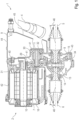
- FIG.1 shows a schematic representation of an embodiment of a drive train 1 in a rear sectional view.
- the drive train 1 is intended for use in a motor vehicle.
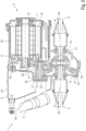
- Fig. 3 The drive train 1 is shown in a schematic 3D representation in a front view.
- the drive train 1 comprises a drive unit 2, a steering gear 3, a steering shaft 4, a first propeller shaft 5, and a second propeller shaft 6.
- the drive unit 2 comprises an electric machine 7, a transmission unit 8, and a pulse-controlled inverter 9.
- the electric machine 7 and the pulse-controlled inverter 9 are arranged on two opposite sides of the transmission unit 8.
- the transmission unit 8 is thus arranged between the pulse-controlled inverter 9 and the electric machine 7.
- the electric machine 7 has a drive shaft 10, and the transmission unit 8 has a transmission shaft 11. It is conceivable for the transmission unit 8 to have additional transmission shafts to form further transmission stages.
- the drive shaft 10 and the transmission shaft 11 run essentially horizontally and essentially perpendicular to a direction of travel 12 of the motor vehicle.
- the drive shaft 10 and The transmission shaft 11 is thus arranged in a transverse direction of the motor vehicle.
- the term "essentially” here means that the deviation from this transverse direction does not exceed the manufacturing tolerances.
- the steering gear 3 is arranged in front of the drive unit 2 in the direction of travel 12 (forward direction of travel of the vehicle). This allows understeering behavior to be achieved even in a rear-heavy motor vehicle. Such rear-heavy behavior is caused, for example, by a vehicle battery, which is designed to be correspondingly large and heavy to supply the electric motor 7. The rear-heavy behavior can also be caused by another electric motor arranged on a rear axle of the motor vehicle.
- the steering gear 3 can be functionally connected to a steering wheel of the motor vehicle by means of the steering shaft 4.
- the steering wheel, the steering shaft 4, and the steering gear 3 enable the motor vehicle to corner.
- the steering shaft 4 is arranged partially laterally next to the drive unit 2.
- the steering shaft 4 is thus arranged laterally next to an end face of the drive unit 2 running parallel to the longitudinal direction of the motor vehicle.
- the transmission unit 8 further comprises a differential 13, wherein the differential 13 is connectable to a first front wheel of the motor vehicle by means of the first propeller shaft 5, and wherein the differential 13 is effectively connectable to a second front wheel of the motor vehicle by means of the second propeller shaft 6.
- the steering gear 3 is thus arranged in particular in the direction of travel 12 (forward direction of travel of the vehicle) in front of the first propeller shaft 5 and in front of the second propeller shaft 6, as can be seen from the figures, taking into account the arrow "12" for the forward direction of travel.
- the differential 13 is arranged substantially centrally on a longitudinal axis 14 of the motor vehicle, which extends centrally in the motor vehicle, wherein a length of the first propeller shaft 5 substantially corresponds to a length of the second propeller shaft 6.
- the drive unit 2 is arranged and/or configured such that the drive unit 2 can be arranged in both a right-hand drive vehicle and a left-hand drive vehicle.
- Fig. 1 shows the drive unit 2 in the right-hand drive vehicle
- Fig. 2 in the left-hand drive vehicle.
- the arrangement of the drive unit 2 in the right-hand drive vehicle is rotated by 180° to a vertical axis 15 or around a vertical axis 15 compared to the arrangement of the drive unit in the left-hand drive vehicle.
- the steering shaft 4 is arranged to the right of the drive unit 2 in relation to the direction of travel 12 or viewed in the direction of travel 12.
- the steering shaft 4 is arranged to the left of the drive unit 2 in relation to the direction of travel 12 or as seen in the direction of travel 12.
- the electric motor 7 is located on a side of the transmission unit 8 facing away from the steering shaft 4.
- the steering shaft 4 thus runs a short distance apart from the pulse-controlled inverter 9.
- the steering shaft 4 is designed as a single-piece or multi-piece unit.
- the steering shaft 4 optionally has a universal joint.
- Fig. 4 shows a schematic, light 3D representation of the drive unit 2 of the drive train 1 in a left-hand drive vehicle in a front view.
- Fig. 5 The drive train 1 in a left-hand drive vehicle is shown in a schematic 3D representation in a front view.
- Fig. 6 shows a schematic 3D representation of the drive train 1 in a left-hand drive vehicle in a rear view.
- Fig. 4 to 6 The same reference numerals are used as for the previous figures. Fig. 4 to 6 In particular, the mechanical connection of the drive unit 2 is evident.
- the drive unit 2 has a drive unit housing 16. On the drive unit housing 16, a plurality of A-side fastening points 18 are formed on a first, A-side 17 of the drive unit housing 16. On the drive unit housing 16, a plurality of B-side fastening points 20 are formed on a second, B-side 19 of the drive unit housing 16, opposite the A-side 17.
- the drive unit housing 16 is fastened by means of at least two of the A-side fastening points 18 to a front unit console 21 and by means of at least two of the B-side fastening points 20 to a rear unit console 22. This situation is shown in the Fig. 5 and 6 shown.
- the power unit housing 16 is attached to the front unit console 21 by means of at least two of the B-side attachment points 20 and to the rear unit console 22 by means of at least two of the A-side attachment points 18.
- the front unit console 21 and the rear unit console 22 are formed on the body 23 of the motor vehicle or connected to the chassis.
- An arrangement of the A-side attachment points 18 relative to one another corresponds to an arrangement of the B-side attachment points 20 relative to one another, wherein the respective arrangement is mirrored on a vertical plane running centrally in a transverse direction through the drive unit housing 16.
- the A-side attachment points 18 and the B-side attachment points 20 thus have the same "pattern.” Due to this identical "pattern," the front unit console 21 and the rear unit console 22 can be universally used in both right-hand drive and left-hand drive vehicles without requiring any structural modifications to the front unit console 21 and the rear unit console 22.
- the front unit console 21 and the rear unit console 22 each have a vertically aligned plate. Horizontal holes are drilled into the front unit console 21 and the rear unit console 22, by means of which the front unit console 21 and the rear unit console 22 are fastened to the drive unit housing 16. Appropriate screws or bolts are used for this purpose. Other fastening methods between the front unit console 21 and the rear unit console 22 and the drive unit housing 16 are conceivable.
- A-side attachment points 18 and five B-side attachment points 20 There are a total of five A-side attachment points 18 and five B-side attachment points 20.
- the connection between the drive unit housing 16 and the front unit console 21 is implemented using all five attachment points on the A-side 17 or the B-side 19.
- the connection between the drive unit housing 2 and the rear unit console 22 is implemented using three of the five attachment points on the A-side 17 or the B-side 19. This takes into account the different load situations on the front unit console 21 and the rear unit console 22.
- the five attachment points are divided into three upper and two lower attachment points, with the rear unit console 22 being connected to the drive unit housing 16 using the two lower attachment points and a central upper attachment point.
- a coolant inlet 24 and a coolant outlet 25 are arranged on the A-side 17 of the drive unit housing 2, and a coolant inlet 26 and a coolant outlet 27 are arranged on the B-side 19 of the drive unit housing 2.
- a cooling fluid can be supplied to the drive unit housing 2 via one of the coolant inlets 24 or 26.
- a cooling fluid can be discharged from the drive unit housing 2 via one of the coolant outlets 25 or 27. Either the coolant inlet 24 and the coolant outlet 25 of the A-side 17, or the coolant inlet 26 and the coolant outlet 27 of the B-side 19 are each closed by a plug and thus rendered inoperative.
- connecting lines and/or connecting hoses are sealingly connected to the coolant inlet 24 or 26 and the coolant outlet 25 or 27.
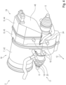
- Fig. 7 shows a schematic 3D representation of the drive unit 2 of the drive train 1 in a side view in section.
- Fig. 7 the same reference numerals are used as for the previous figures.
- the coolant outlet 25 of the A-side 17 and the coolant outlet 27 of the B-side 19 are connected to each other by means of a through-bore 28, which extends in the direction of travel 12. It is conceivable that the coolant inlet 24 of the A-side 17 and the coolant inlet 26 of the B-side 19 are also connected to each other by a comparable through-bore.
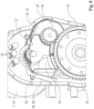
- Fig.8 The transmission unit 8 of the drive train 1 is shown in a schematic 3D representation in a side view. Parts of the drive unit housing 16 have been omitted in order to make the components within the drive unit housing 16 visible. For the same components, Fig. 8 the same reference numerals are used as for the previous figures.
- An input gear 29 and an output gear 30 are arranged or formed on the transmission shaft 11.
- a drive gear 31 is formed or arranged on the drive shaft 10.
- the differential 13 has a differential gear 32.
- the drive gear 31 and the input gear 29 are in mesh with one another, and the output gear 30 and the differential gear 32 are in mesh with one another.
- the drive gear 31, the input gear 29, the output gear 30, and/or the differential gear 32 have, in particular, helical gearing. It would also be conceivable to use straight gearing for at least two of the meshing gears.
- the drive gear 31, the input gear 29, the output gear 30, and the differential gear 32 form a spur gear transmission with two gear stages.
- At least one oil tank 33 is arranged in the drive unit housing 16. At least one oil sump area 34 is formed in the drive unit housing 16, wherein the differential gear 32 is arranged splashing in the oil sump area 34.
- the transmission unit 8 is filled with oil, which collects at least partially in the oil sump area 34 due to gravity, or at least partially repeatedly flows back into the oil sump area 34 during operation of the transmission unit 8.
- Adjacent to the oil tank 33 are A first oil catcher 35 and a second oil catcher 36 are arranged, with a left-hand drive guide region 37 being formed on the first oil catcher 35 and a right-hand drive guide region 38 being formed on the second oil catcher 36.
- oil thrown up from the oil sump region 34 by the differential gear 32 can be fed to the oil tank 33 in a first direction of rotation of the differential gear 32.
- the first direction of rotation of the differential gear 32 occurs when the motor vehicle, which is designed as a left-hand drive vehicle, is traveling forward.
- the right-hand drive guide area 38 By means of the right-hand drive guide area 38, oil thrown up from the oil sump area 34 by the differential gear 32 can be fed to the oil tank 33 in a second direction of rotation of the differential gear 32, opposite to the first direction of rotation.
- the second direction of rotation of the differential gear 32 occurs when the motor vehicle designed as a right-hand drive vehicle is traveling forward.
- the oil tank is thus filled with oil both when used in a left-hand drive vehicle and in a right-hand drive vehicle when the motor vehicle is traveling.
- the left-hand drive guide area 37 and the right-hand drive guide area 38 each have a scraper edge, from which the oil drips or flows from the left-hand drive guide area 37 or the right-hand drive guide area 38 into the oil tank 33 arranged below.
- An oil tank region 39 is formed in the oil tank 33, with the drive gear 31 being arranged in a splashing manner in the oil tank region 39.
- Several contacts 40 are arranged in the drive unit housing 16, with electrical energy being transmittable between the pulse-controlled inverter 9 and the electric machine 7 by means of the contacts 40.
- the electrical energy is transmittable in both directions, so that energy for driving the motor vehicle can be provided by the electric machine 7, with kinetic energy of the motor vehicle also being recuperated by the electric machine 7 and transmitted via the pulse-controlled inverter 9, for example, to a battery of the motor vehicle.
- the contacts 40 can be cooled by means of the oil thrown up from the oil tank region 39 by the drive gear 31. This ensures that the contacts do not exceed a maximum permissible temperature during operation of the motor vehicle.
- the oil tank area 39 is adapted to the shape and size of the drive gear 31, so that it is ensured that during operation of the motor vehicle the drive gear 31 is always immersed far enough into the oil accumulating in the oil tank area 39.
- the gear shaft 11 is mounted in the drive unit housing 16 by means of at least two bearings 41.
- the bearings 41 of the gear shaft 11 have in both directions of rotation of the
- the transmission shaft 11 has such an arrangement and/or dimensioning that the function of the two bearings 41 is ensured for a service life predetermined in the design of the bearings 41 for forward travel of the motor vehicle.
- the direction of rotation of the transmission shaft 11 in a left-hand drive vehicle is opposite when the motor vehicle is traveling forward. Therefore, due to the desired flexibility, it is not sufficient to design one of the two bearings 41 only for reversing the motor vehicle.
- the resulting additional costs due to partially "oversized" bearings 41 are offset by the selection of uniform components and the associated reduction in procurement costs.
- all other components of the transmission unit 8, such as the gearing are designed for a service life predetermined in the design of these components for forward travel of the motor vehicle for both directions of rotation of the transmission shaft 11.
- the drive unit housing 16 is constructed in several parts and has an electric machine sub-housing 42, a transmission sub-housing 43, and a pulse-controlled inverter sub-housing 44.
- the electric machine 7 is arranged in the electric machine sub-housing 42, the transmission unit 8 in the transmission sub-housing 43, and the pulse-controlled inverter 9 in the pulse-controlled inverter sub-housing 44.
- the differential 13 is also arranged in the transmission sub-housing 43.
- a bevel 45 is formed on the pulse-controlled inverter sub-housing 44, with an axis of the steering shaft 4 being arranged essentially parallel to the bevel 45 in an area adjacent to the bevel 45. Minor differences in parallelism are tolerable.
- the bevel 45 is formed on an end face of the pulse inverter sub-housing 44 facing away from the gear unit 8.
- the bevel 45 has an angle to a plane running perpendicular to the gear shaft 11, wherein the distance of the end face of the pulse inverter sub-housing 44 facing away from the gear unit 8 to the gear unit 43 is greater in an upper region of the end face of the pulse inverter sub-housing 44 facing away from the gear unit 8 than in the lower region of the end face of the pulse inverter sub-housing 44 facing away from the gear unit 8. This takes into account the fact that the Steering shaft 4 runs from a steering wheel arranged above the steering gear 3 obliquely downwards to a vehicle center.
- the first propeller shaft 5 and the second propeller shaft 6 are each arranged at an angle of deflection 46 to a horizontal plane.
- the deflection angles 46 of the first propeller shaft 5 and the second propeller shaft 6 have the same values.
- the deflection angles 46 of the first propeller shaft 5 and the second propeller shaft 6 are, in particular, less than 7.5°. Due to these small deflection angles 46, the drive train 1 is highly efficient and results in good driving dynamics of the motor vehicle.
- the drive train 1 can be used in a purely electrically driven motor vehicle, wherein only the described electric machine 7 and no further drive is present, wherein only the first propeller shaft 5 and the second propeller shaft 6 and thus a front axle of the motor vehicle can be driven.
- the drive train 1 could also be used in an all-wheel drive vehicle.
- at least one clutch would be arranged in the drive train, with the at least one clutch being able to decouple the first propeller shaft 5 and the second propeller shaft 6 individually or jointly from the electric motor 7.
Landscapes
- Engineering & Computer Science (AREA)
- Mechanical Engineering (AREA)
- Chemical & Material Sciences (AREA)
- Combustion & Propulsion (AREA)
- Transportation (AREA)
- General Engineering & Computer Science (AREA)
- Arrangement Or Mounting Of Propulsion Units For Vehicles (AREA)
- Hybrid Electric Vehicles (AREA)
Description
Die Erfindung betrifft ein Kraftfahrzeug mit einem Antriebsstrang gemäß den Merkmalen des Oberbegriffes des Patentanspruches 1.The invention relates to a motor vehicle with a drive train according to the features of the preamble of patent claim 1.
Im Stand der Technik sind Antriebsstränge für Kraftfahrzeuge mit einem Antriebsaggregat, einem Lenkgetriebe, einer Lenkwelle, einer ersten und einer zweiten Gelenkwelle bekannt. Das entsprechende Antriebsaggregat weist eine Elektromaschine, eine Getriebeeinheit und einen Pulswechselrichter auf, wobei die Elektromaschine und der Pulswechselrichter auf zwei gegenüberliegenden Seiten der Getriebeeinheit angeordnet sind. Eine Antriebswelle der Elektromaschine und eine Getriebewelle der Getriebeeinheit verlaufen im Wesentlichen horizontal und im Wesentlichen senkrecht zu einer Fahrtrichtung des Kraftfahrzeugs. Aus Gründen der Fahrdynamik ist das Lenkgetriebe in Fahrtrichtung (Vorwärts-Fahrtrichtung) vor dem Antriebsaggregat angeordnet. Damit ist gemeint, dass vom Kraftfahrzeug von vorne nach hinten aus gesehen zuerst das Lenkgetriebe und dahinter dann das Antriebsaggregat angeordnet ist. Mittels der Lenkwelle ist das Lenkgetriebe mit einem Lenkrad des Kraftfahrzeugs funktional wirksam verbindbar. Deswegen ist die Lenkwelle seitlich neben dem Antriebsaggregat angeordnet. Die Getriebeeinheit weist weiterhin ein Differential auf, wobei das Differential mittels der ersten Gelenkwelle mit einem ersten Vorderrad des Kraftfahrzeuges wirksam verbindbar ist. Das Differential ist des Weiteren mittels der zweiten Gelenkwelle mit einem zweiten Vorderrad des Kraftfahrzeuges wirksam verbindbar.Drivetrains for motor vehicles comprising a drive unit, a steering gear, a steering shaft, and a first and a second cardan shaft are known in the prior art. The corresponding drive unit comprises an electric motor, a transmission unit, and a pulse-controlled inverter, wherein the electric motor and the pulse-controlled inverter are arranged on two opposite sides of the transmission unit. A drive shaft of the electric motor and a transmission shaft of the transmission unit extend essentially horizontally and essentially perpendicular to a direction of travel of the motor vehicle. For reasons of driving dynamics, the steering gear is arranged in front of the drive unit in the direction of travel (forward direction of travel). This means that, viewed from front to rear of the motor vehicle, the steering gear is arranged first, followed by the drive unit. By means of the steering shaft, the steering gear can be functionally connected to a steering wheel of the motor vehicle. Therefore, the steering shaft is arranged laterally next to the drive unit. The transmission unit further comprises a differential, wherein the differential can be effectively connected to a first front wheel of the motor vehicle by means of the first cardan shaft. The differential can also be effectively connected to a second front wheel of the motor vehicle by means of the second drive shaft.
Die
In der
Die
So wird in der
Schließlich ist in der
Bei den bekannten Antriebssträngen ergeben sich Probleme bei der Integration des Antriebsaggregates in das Kraftfahrzeug. Der zur Verfügung stehende Bauraum im Kraftfahrzeug wird nämlich nicht optimal genutzt, letzteres insbesondere in Abhängigkeit davon, ob das Antriebsaggregat in einem Linkslenkerfahrzeug oder in einem Rechtslenkerfahrzeug angeordnet wird. So entstehen bei Einsatz der bekannten Antriebsstränge jeweils ungenutzte Bereiche im Bauraum. Teilweise müssen sogar an das Antriebsaggregat angrenzende Bauteile des Antriebsstranges dann versetzt angeordnet werden, was sich negativ auf die Effizienz bzw. den Wirkungsgrad des Antriebsstranges und somit des Kraftfahrzeugs auswirkt. Weiterhin sind die bekannten Antriebsstränge nur mit entsprechenden konstruktiven Anpassungen in unterschiedlichen Fahrzeugvarianten (Linkslenkerfahrzeug / Rechtslenkerfahrzeug) einsetzbar, was den Entwicklungsaufwand, den Herstellungsaufwand und den Montageaufwand der Antriebsstränge erhöht.With conventional drivetrains, problems arise when integrating the drive unit into the motor vehicle. The available installation space in the vehicle is not used optimally, the latter particularly depending on whether the drive unit is installed in a left-hand drive or a right-hand drive vehicle. This results in unused areas in the installation space when using conventional drivetrains. In some cases, drivetrain components adjacent to the drive unit must then be offset, which negatively impacts the efficiency of the drivetrain and thus the motor vehicle. Furthermore, the conventional drivetrains can only be used in different vehicle variants (left-hand drive / right-hand drive) with appropriate design adaptations, which increases the development effort, manufacturing effort, and assembly effort of the drivetrains.
Der Erfindung liegt daher die Aufgabe zugrunde, den Antriebsstrang für ein Kraftfahrzeug nun derart auszugestalten und weiterzubilden, dass der Entwicklungsaufwand, der Herstellungsaufwand und/oder der Montageaufwand bzw. die damit verbundenen Kosten verringert sind und/oder dass der zur Verfügung stehende Bauraum, insbesondere auch unter Berücksichtigung der Anordnung einer Elektromaschine und/oder deren Leistung, möglichst optimal ausnutzbar ist.The invention is therefore based on the object of designing and developing the drive train for a motor vehicle in such a way that the development effort, the manufacturing effort and/or the assembly effort or the associated costs are reduced and/or that the available installation space, in particular also under Taking into account the arrangement of an electric machine and/or its power, it can be used as optimally as possible.
Diese der Erfindung zugrundeliegende Aufgabe wird nun für ein Kraftfahrzeug mit den Merkmalen des Patentanspruchs 1 gelöst.This problem underlying the invention is now solved for a motor vehicle with the features of patent claim 1.
Das Grundprinzip der Erfindung liegt zunächst im Wesentlichen nun darin, dass das Differential im Wesentlichen mittig auf einer im Kraftfahrzeug mittig verlaufenden Längsachse des Kraftfahrzeugs angeordnet ist, wobei eine Länge der ersten Gelenkwelle einer Länge der zweiten Gelenkwelle im Wesentlichen entspricht. Hierbei ist das Antriebsaggregat weiterhin so ausgebildet, dass das Antriebsaggregat sowohl in einem Rechtslenkerfahrzeug wie auch in einem Linkslenkerfahrzeug anordnenbar ist, wobei die Anordnung des Antriebsaggregats im Rechtslenkerfahrzeug gegenüber der Anordnung des Antriebsaggregats im Linkslenkerfahrzeug um 180° zu einer vertikalen Hochachse gedreht ausgeführt ist. Wenn das Antriebsaggregat in dem Rechtslenkerfahrzeug angeordnet ist, dann ist die Lenkwelle in Bezug zur Fahrtrichtung rechts neben dem Antriebsaggregat angeordnet. Wenn das Antriebsaggregat demgegenüber in dem Linkslenkerfahrzeug angeordnet ist, dann ist die Lenkwelle in Bezug zur Fahrtrichtung links neben dem Antriebsaggregat angeordnet. Die vertikale Hochachse verläuft hierbei insbesondere genau mittig im Kraftfahrzeug und kreuzt die insbesondere genau mittig verlaufende Längsachse des Kraftfahrzeuges.The basic principle of the invention is essentially that the differential is arranged essentially centrally on a longitudinal axis running centrally in the motor vehicle, wherein a length of the first propeller shaft essentially corresponds to a length of the second propeller shaft. In this case, the drive unit is further designed such that the drive unit can be arranged in both a right-hand drive vehicle and a left-hand drive vehicle, wherein the arrangement of the drive unit in the right-hand drive vehicle is rotated by 180° to a vertical axis compared to the arrangement of the drive unit in the left-hand drive vehicle. If the drive unit is arranged in the right-hand drive vehicle, the steering shaft is arranged to the right of the drive unit with respect to the direction of travel. If, in contrast, the drive unit is arranged in the left-hand drive vehicle, the steering shaft is arranged to the left of the drive unit with respect to the direction of travel. The vertical axis runs in particular exactly centrally in the motor vehicle and intersects the longitudinal axis of the motor vehicle, which in particular runs exactly centrally.
Die im Wesentlichen mittige Anordnung des Differentials ermöglicht die Ausbildung der im Wesentlichen gleichlangen Gelenkwellen. Mit dem Ausdruck "im Wesentlichen mittig" in Bezug zum Differential ist hier nun gemeint, dass das Differrential bis zu ± 50mm außermittig in Bezug zu dem Mittelpunkt einer Querachse des Kraftfahrzeugs bzw. bis zu ± 50mm außermittig in Bezug zu einer genau mittig verlaufenden Längsachse des Kraftfahrzeuges anordnenbar ist. Mit dem Ausdruck "im Wesentlichen" in Bezug zu den Gelenkwellen ist hier gemeint, dass die Länge der ersten Gelenkwelle von der Länge der zweiten Gelenkwelle nur um unvermeidliche Fertigungstoleranzen abweicht oder dass die Länge der ersten Gelenkwelle von der Länge der zweiten Gelenkwelle um weniger als 52mm abweicht. Die im Wesentlichen gleichlangen Gelenkwellen führen auch zu einer erhöhten Effizienz bzw. zu einem verbesserten Wirkungsgrad des Antriebsstranges.The essentially central arrangement of the differential enables the design of drive shafts of essentially equal length. The term "essentially central" in relation to the differential means that the differential can be arranged up to ± 50 mm off-center with respect to the center of a transverse axis of the vehicle or up to ± 50 mm off-center with respect to a precisely central longitudinal axis of the vehicle. The term "essentially" in relation to the drive shafts means that the length of the first drive shaft deviates from the length of the second drive shaft only by unavoidable manufacturing tolerances, or that the length of the first drive shaft deviates from the length of the second drive shaft by less than 52 mm. The essentially equal-length drive shafts also lead to increased efficiency or improved efficiency of the drivetrain.
Dadurch, dass das entsprechende Antriebsaggregat sowohl im Rechtslenkerfahrzeug wie auch im Linkslenkerfahrzeug einsetzbar ist, können besonders hohe Stückzahlen dieses Antriebsaggrates, nämlich eben sowohl für Rechtslenker- wie auch für Linkslenkerfahrzeuge realisiert werden. Das führt zu einer Kostenreduktion sowohl bei der Entwicklung wie auch bei der Herstellung des Antriebsaggregats bzw. bei der Beschaffung der Bauteile des Antriebsaggregates. Der Einsatz des Antriebsaggregats sowohl im Rechtslenkerfahrzeug wie auch im Linkslenkerfahrzeug wird insbesondere durch die Eigenschaft der Elektromaschine ermöglicht, in beiden Drehrichtungen der Antriebswelle gleich gute Leistung abgeben zu können.Because the corresponding drive unit can be used in both right-hand drive and left-hand drive vehicles, particularly high quantities of this drive unit can be produced, namely for both right-hand drive and left-hand drive vehicles. This leads to cost reductions in both the development and production of the drive unit, as well as in the procurement of the drive unit's components. The use of the drive unit in both right-hand drive and left-hand drive vehicles is made possible, in particular, by the electric motor's ability to deliver equally good power in both directions of rotation of the drive shaft.
Die Elektromaschine ist vorzugsweise sowohl im Rechtslenkerfahrzeug wie auch im Linkslenkerfahrzeug auf einer der Lenkwelle abgewandten Seite der Getriebeeinheit angeordnet.The electric motor is preferably arranged on a side of the transmission unit facing away from the steering shaft in both right-hand drive vehicles and left-hand drive vehicles.
Die Elektromaschine weist zur Bereitstellung einer hohen Antriebsleistung eine relativ große Ausdehnung in axialer Richtung der Antriebswelle auf. Weiterhin ist auch der Durchmesser der Elektromaschine relativ groß. Relativ ist hier in Bezug zur Größe des Pulswechselrichters gemeint. Aufgrund der Anordnung der Elektromaschine auf einer der Lenkwelle abgewandten Seite der Getriebeeinheit ist die Lenkwelle so besonders nah zu einer mittig im Fahrzeug verlaufenden Längsachse des Fahrzeuges an dem Antriebsaggregat vorbeiführbar, ohne dass das Antriebsaggregat dabei durch die Lenkwelle touchiert wird. Die Lenkwelle ist so insbesondere auf eine Mitte eines Fahrzeugsitzes ausrichtbar, nämlich insbesondere auf eine Mitte eines linken Fahrzeugsitzes im Linkslenkerfahrzeug und insbesondere auf eine Mitte eines rechten Fahrzeugsitzes im Rechtslenkerfahrzeug. Auch die Verbindung zwischen Lenkwelle und Lenkgetriebe ist somit besonders nah einer mittig im Fahrzeug verlaufenden Längsachse des Fahrzeuges ausführbar. Das wirkt sich positiv auf mögliche Ausführungen des Lenkgetriebes und somit positiv auf das Lenkverhalten des Fahrzeuges aus.To provide high drive power, the electric motor has a relatively large extension in the axial direction of the drive shaft. Furthermore, the diameter of the electric motor is also relatively large. "Relative" here refers to the size of the pulse-controlled inverter. Due to the arrangement of the electric motor on a side of the gear unit facing away from the steering shaft, the steering shaft can be guided past the drive unit particularly close to a longitudinal axis running through the center of the vehicle, without the drive unit being touched by the steering shaft. The steering shaft can thus be aligned in particular to the center of a vehicle seat, namely in particular to the center of a left-hand vehicle seat in a left-hand drive vehicle and in particular to the center of a right-hand vehicle seat in a right-hand drive vehicle. The connection between the steering shaft and the steering gear can therefore also be implemented particularly close to a longitudinal axis running through the center of the vehicle. This has a positive effect on possible designs of the steering gear and thus on the steering behavior of the vehicle.
In einer bevorzugten Ausführungsform des Antriebsstranges weist das Antriebsaggregat ein Antriebsaggregat-Gehäuse auf, wobei an dem Antriebsaggregat-Gehäuse auf einer ersten, A-Seite des Antriebsaggregat-Gehäuses mehrere A-Seiten-Befestigungspunkte ausgebildet sind. An dem Antriebsaggregat-Gehäuse sind weiterhin auf einer zweiten, der A-Seite gegenüberliegenden B-Seite des Antriebsaggregat-Gehäuses mehrere B-Seiten-Befestigungspunkte ausgebildet. Das Antriebsaggregat-Gehäuse ist mittels zumindest zwei der A-Seiten-Befestigungspunkte an einer vorderen, Front-Einheitskonsole und mittels zumindest zwei der B-Seiten-Befestigungspunkte an einer hinteren Heck-Einheitskonsole befestigbar. Alternativ ist das Antriebsaggregat-Gehäuse mittels zumindest zwei der B-Seiten-Befestigungspunkte an der vorderen, Front-Einheitskonsole und mittels zumindest zwei der A-Seiten-Befestigungspunkte an der hinteren Heck-Einheitskonsole befestigbar. Die Front-Einheitskonsole und die Heck-Einheitskonsole sind an einer Karosserie des Kraftfahrzeuges ausgebildet.In a preferred embodiment of the drive train, the drive unit has a drive unit housing, wherein a plurality of A-side fastening points are formed on the drive unit housing on a first, A-side of the drive unit housing. Furthermore, a plurality of B-side fastening points are formed on the drive unit housing on a second, B-side of the drive unit housing opposite the A-side. The drive unit housing can be fastened to a front unit console by means of at least two of the A-side fastening points and to a rear unit console by means of at least two of the B-side fastening points. Alternatively, the drive unit housing can be fastened to the front unit console by means of at least two of the B-side fastening points and to the rear unit console by means of at least two of the A-side fastening points. The front unit console and the rear unit console are formed on a body of the motor vehicle.
Mittels der A-Seiten-Befestigungspunkte und der B-Seiten-Befestigungspunkte ist eine sichere Verbindung zwischen dem Antriebsaggregat und der Karosserie sowohl in einem Rechtslenkerfahrzeug wie auch in einem Linkslenkerfahrzeug ermöglicht. Ein jeder der Befestigungspunkte weist zum Beispiel ein Innengewinde auf, so dass das Antriebsaggregat mittels einer Schraube mit der Front-Einheitskonsole und der Heck-Einheitskonsole verbindbar ist. Die Innengewinde der Befestigungspunkte verlaufen dabei vorzugsweise in einer waagerechten Richtung. Andere Verbindungstechniken zwischen dem Antriebsaggregat und den beiden Einheitskonsolen sind denkbar. Weiterhin weist ein jeder Befestigungspunkt jeweils eine Übertragungsfläche auf, wobei mittels dieser Übertragungsflächen jeweils eine Kraft und / oder ein Moment zwischen dem Antriebsaggregat und den beiden Einheitskonsolen übertragbar ist. Die Front-Einheitskonsole ist in Fahrtrichtung vor dem Antriebsaggregat und die Heck-Einheitskonsole ist in Fahrtrichtung hinter dem Antriebsaggregat angeordnet.The A-side and B-side attachment points enable a secure connection between the drive unit and the body in both right-hand drive and left-hand drive vehicles. Each of the attachment points has, for example, an internal thread, so that the drive unit can be connected to the front unit console and the rear unit console using a screw. The internal threads of the attachment points preferably run in a horizontal direction. Other connection techniques between the drive unit and the two unit consoles are conceivable. Furthermore, each attachment point has a transmission surface, whereby a force and/or a moment can be transmitted between the drive unit and the two unit consoles via these transmission surfaces. The front unit console is arranged in front of the drive unit in the direction of travel, and the rear unit console is arranged behind the drive unit in the direction of travel.
Bevorzugterweise entspricht eine Anordnung der A-Seiten-Befestigungspunkte zueinander einer Anordnung der B-Seiten-Befestigungspunkte zueinander, wobei insbesondere die Anordnung der A-Seiten-Befestigungspunkte zu der Anordnung der B-Seiten-Befestigungspunkte an einer vertikalen, mittig in einer Querrichtung durch das Antriebsaggregat-Gehäuse laufenden Ebene gespiegelt ist.Preferably, an arrangement of the A-side fastening points relative to one another corresponds to an arrangement of the B-side fastening points relative to one another, wherein in particular the arrangement of the A-side fastening points is mirrored to the arrangement of the B-side fastening points on a vertical plane running centrally in a transverse direction through the drive unit housing.
Jeweils einer der A-Seiten-Befestigungspunkte und einer der B-Seiten-Befestigungspunkte liegen dabei bevorzugterweise in einer in Längsrichtung des Kraftfahrzeuges verlaufenden Linie. Auch wenn die Front-Einheitskonsole und die Heck-Einheitskonsole unterschiedlich ausgeführt sind, was aufgrund der Belastungen der Front-Einheitskonsole und der Heck-Einheitskonsole durchaus sinnvoll ist, ist das Antriebsaggregat mittels der A-Seiten-Befestigungspunkte und der B-Seiten-Befestigungspunkte sowohl in dem Rechtslenkerfahrzeug wie auch dem Linkslenkerfahrzeug mit den beiden jeweiligen Einheitskonsolen verbindbar.One of the A-side attachment points and one of the B-side attachment points are preferably located in a line running longitudinally of the vehicle. Even if the front unit console and the rear unit console are designed differently, which makes sense given the loads on the front unit console and the rear unit console, the drive unit can be connected to the two respective unit consoles using the A-side attachment points and the B-side attachment points in both right-hand drive and left-hand drive vehicles.
In einer weiteren Ausführungsform des Antriebsstranges sind fünf A-Seiten-Befestigungspunkte und fünf B-Seiten-Befestigungspunkte vorhanden bzw. ausgebildet.In a further embodiment of the drive train, five A-side attachment points and five B-side attachment points are present or formed.
So können die Kräfte und / oder Momente, welche zwischen dem Antriebsaggregat und den beiden Einheitskonsolen wirken, besonders gut und trotzdem mit einem vertretbaren konstruktiven Aufwand auf die verschiedenen Befestigungspunkte verteilt werden. Insbesondere zur Aufnahme der Momente sind voneinander beabstandet angeordnete Verbindungen zwischen den beiden Einheitskonsolen und dem Antriebsaggregat sinnvoll.This allows the forces and/or moments acting between the drive unit and the two standard brackets to be distributed particularly effectively across the various attachment points, yet with reasonable design effort. Spaced connections between the two standard brackets and the drive unit are particularly useful for absorbing these moments.
In einer bevorzugten Ausführungsform des Antriebsstranges sind jeweils ein Kühlmittelzulauf und ein Kühlmittelablauf auf der A-Seite des Antriebsaggregat-Gehäuses angeordnet. Weiterhin sind jeweils ein Kühlmittelzulauf und ein Kühlmittelablauf auf der B-Seite des Antriebsaggregat-Gehäuses angeordnet. Mittels eines der Kühlmittelzuläufe ist dem Antriebsaggregat-Gehäuse ein Kühlfluid zuführbar, wobei mittels eines der Kühlmittelabläufe ein Kühlfluid aus dem Antriebsaggregat-Gehäuse abführbar ist. Entweder der Kühlmittelzulauf und der Kühlmittelablauf der A-Seite, oder der Kühlmittelzulauf und der Kühlmittelablauf der B-Seite sind mittels jeweils eines Stopfens verschlossen und somit außer Funktion gesetzt.In a preferred embodiment of the drive train, a coolant inlet and a coolant outlet are each arranged on the A side of the drive unit housing. Furthermore, a coolant inlet and a coolant outlet are each arranged on the B side of the drive unit housing. A cooling fluid can be supplied to the drive unit housing via one of the coolant inlets, and a cooling fluid can be discharged from the drive unit housing via one of the coolant outlets. Either the coolant inlet and the coolant outlet on the A side, or the coolant inlet and the coolant outlet on the B side, are each closed by a plug and thus rendered inoperative.
Die Rohrleitungen oder Schläuche zur Zu- und zur Abfuhr des Kühlfluids sind in Fahrtrichtung vor dem Antriebsaggregat angeordnet. Denkbar ist alternativ auch eine Anordnung der Rohrleitungen oder Schläuche zur Zu- und zur Abfuhr des Kühlfluids in Fahrtrichtung hinter dem Antriebsaggregat. Dadurch, dass auf beiden Seiten des Antriebsaggregat-Gehäuses jeweils ein Kühlmittelzulauf und ein Kühlmittelablauf vorhanden sind, sind Rohrleitungen oder Schläuche sowohl im Rechtslenkerfahrzeug wie auch im Linkslenkerfahrzeug an das Antriebsaggregat anschließbar. Die beiden nicht genutzten Öffnungen, nämlich der nicht genutzte Kühlmittelzulauf und der nicht genutzte Kühlmittelablauf werden z.B. mittels jeweils eines Schraubstopfens dichtend verschlossen. Auf diese Weise wird die Flexibilität der Einsatzmöglichkeiten des Antriebsaggregats weiter erhöht. Der Kühlfluidkreislauf inklusive etwaiger Rohrleitungen und / oder Schläuche kann ohne Änderungen bezüglich des Antriebsaggregates sowohl im Rechtslenkerfahrzeug wie auch im Linkslenkerfahrzeug eingesetzt werden.The pipes or hoses for supplying and discharging the cooling fluid are arranged in front of the drive unit in the direction of travel. Alternatively, it is also conceivable to arrange the pipes or hoses for supplying and discharging the cooling fluid behind the drive unit in the direction of travel. Because there is a coolant inlet and a coolant outlet on both sides of the drive unit housing, pipes or hoses can be connected to the drive unit in both right-hand drive and left-hand drive vehicles. The two unused openings, namely the unused coolant inlet and the unused coolant outlet, are each sealed using a screw plug, for example. This further increases the flexibility of the drive unit's possible applications. The cooling fluid circuit, including any pipes and/or hoses, can be used in both right-hand drive and left-hand drive vehicles without any changes to the drive unit.
Bevorzugterweise sind der Kühlmittelzulauf der A-Seite und der Kühlmittelzulauf der B-Seite und / oder der Kühlmittelablauf der A-Seite und der Kühlmittelablauf der B-Seite mittels einer durchgehenden Bohrung miteinander verbunden. Diese Bohrung verläuft in Fahrtrichtung.Preferably, the coolant inlet on the A-side and the coolant inlet on the B-side and/or the coolant outlet on the A-side and the coolant outlet on the B-side are connected to each other by means of a through bore. This bore runs in the direction of travel.
Auf diese Weise sind die beiden Kühlmittelabläufe und / oder die beiden Kühlmittelzuläufe besonders einfach herstellbar. Das wirkt sich sehr positiv auf die Herstellkosten des Antriebsaggregates aus.This makes it particularly easy to manufacture the two coolant outlets and/or the two coolant inlets. This has a very positive effect on the manufacturing costs of the drive unit.
In einer weiteren Ausführungsform des Antriebsstranges sind ein Eingangszahnrad und ein Ausgangszahnrad an der Getriebewelle angeordnet oder ausgebildet. An der Antriebswelle ist ein Antriebszahnrad ausgebildet oder angeordnet. Das Differential weist weiterhin ein Differentialzahnrad auf. Das Antriebszahnrad und das Eingangszahnrad stehen in Eingriff miteinander. Ebenso stehen das Ausgangszahnrad und das Differentialzahnrad in Eingriff miteinander. Insbesondere weisen das Antriebszahnrad, das Eingangszahnrad, das Ausgangszahnrad und / oder das Differentialzahnrad eine Schrägverzahnung auf.In a further embodiment of the drive train, an input gear and an output gear are arranged or formed on the transmission shaft. A drive gear is arranged or formed on the drive shaft. The differential further comprises a differential gear. The drive gear and the input gear are in mesh. with each other. Likewise, the output gear and the differential gear mesh with each other. In particular, the drive gear, the input gear, the output gear, and/or the differential gear have helical teeth.
Die Zahnräder sind dabei als Stirnzahnräder ausgebildet und zu einem Stirnradgetriebe angeordnet. Solche Stirnradgetriebe sind robust und kostengünstig herstellbar. Mittels der Schrägverzahnung kann eine geringe Geräuschentwicklung der gesamten Getriebeeinheit und eine hohe Tragfähigkeit der einzelnen Zahnräder erreicht werden.The gears are designed as spur gears and arranged in a helical gear train. Such spur gear trains are robust and cost-effective to manufacture. The helical gearing allows for low noise levels throughout the entire gear unit and a high load-bearing capacity of the individual gears.
In dem Antriebsaggregat-Gehäuse ist vorteilhafterweise zumindest ein Öltank angeordnet. In dem Antriebsaggregat-Gehäuse ist zudem zumindest ein Ölsumpfbereich ausgebildet, wobei das Differentialzahnrad planschend im Ölsumpfbereich angeordnet ist. Angrenzend zum Öltank sind ein erster und ein zweiter Ölfänger angeordnet, wobei an dem ersten Ölfänger ein Linkslenker-Führungsbereich und dem zweiten Ölfänger ein Rechtslenker-Führungsbereich ausgebildet ist, wobei mittels des Linkslenker-Führungsbereichs von dem Differentialzahnrad aus dem Ölsumpfbereich empor geschleudertes Öl dem Öltank bei einer ersten Drehrichtung des Differentialzahnrads zuführbar ist, und wobei mittels des Rechtslenker-Führungsbereichs von dem Differentialzahnrad aus dem Ölsumpfbereich empor geschleudertes Öl dem Öltank bei einer zweiten, der ersten Drehrichtung entgegengesetzten Drehrichtung des Differentialzahnrads zuführbar ist.At least one oil tank is advantageously arranged in the drive unit housing. At least one oil sump region is also formed in the drive unit housing, with the differential gear being arranged in a splashing manner in the oil sump region. A first and a second oil collector are arranged adjacent to the oil tank, with a left-hand drive guide region being formed on the first oil collector and a right-hand drive guide region being formed on the second oil collector. Oil thrown up from the oil sump region by the differential gear by means of the left-hand drive guide region can be fed to the oil tank in a first direction of rotation of the differential gear, and oil thrown up from the oil sump region by the differential gear by means of the right-hand drive guide region can be fed to the oil tank in a second direction of rotation of the differential gear, opposite to the first direction of rotation.
Das Differentialzahnrad dreht sich bei einer Vorwärtsfahrt des Kraftfahrzeuges im Rechtslenkerfahrzeug im Gegensatz zum Linkslenkerfahrzeug in der entgegensetzten Drehrichtung. Wie oben beschrieben wird dem Öltank in beiden Fällen Öl aus dem Ölsumpfbereich zugeführt. Der Linkslenker-Führungsbereich ist derart angeordnet, dass bei einer Vorwärtsfahrt des Linkslenkerfahrzeugs dem Öltank von dem Differentialzahnrad aus dem Ölsumpfbereich empor geschleudertes Öl mittels des Linkslenker-Führungsbereichs zuführbar ist. Der Rechtslenker-Führungsbereich ist derart angeordnet, dass bei einer Vorwärtsfahrt des Rechtslenkerfahrzeugs dem Öltank von dem Differentialzahnrad aus dem Ölsumpfbereich empor geschleudertes Öl mittels des Rechtslenker-Führungsbereichs zuführbar ist.When the motor vehicle is moving forward, the differential gear in a right-hand drive vehicle rotates in the opposite direction to that in a left-hand drive vehicle. As described above, in both cases, oil is supplied to the oil tank from the oil sump area. The left-hand drive guide area is arranged such that when the left-hand drive vehicle is moving forward, oil thrown up from the oil sump area by the differential gear can be supplied to the oil tank via the left-hand drive guide area. The right-hand drive guide area is arranged such that when the right-hand drive vehicle is moving forward, oil thrown up from the oil sump area by the differential gear can be supplied to the oil tank via the right-hand drive guide area.
Bevorzugterweise ist in dem Öltank ein Öltankbereich ausgebildet, wobei das Antriebszahnrad planschend in dem Öltankbereich angeordnet ist. In dem Antriebsaggregat-Gehäuse sind mehrere Kontakte angeordnet, wobei mittels der Kontakte elektrische Energie zwischen dem Pulswechselrichter und der Elektromaschine übertragbar ist. Die Kontakte sind mittels des von dem Antriebszahnrad aus dem Öltankbereich empor geschleuderten Öls kühlbar.Preferably, an oil tank area is formed in the oil tank, with the drive gear arranged in a splash-like manner within the oil tank area. Several contacts are arranged in the drive unit housing, with electrical energy being transmitted between the pulse-controlled inverter and the electric machine via the contacts. The contacts can be cooled by the oil propelled upwards from the oil tank area by the drive gear.
Aufgrund der hohen elektrischen Energie, welche mittels der Kontakte übertragen wird, entsteht Wärme in den Kontakten. Diese führt zu einer Temperaturerhöhung der Kontakte. Mittels des empor geschleuderten Öls erfolgt eine Abfuhr von Wärme von den Kontakten, so dass die Temperaturerhöhung der Kontakte in einem akzeptablen Bereich bleibt, in welchem die Funktion der Kontakte sichergestellt ist. Der Öltank kann weiterhin zur Schmierung von Lagern genutzt werden, so dass hier Synergieeffekte entstehen.Due to the high electrical energy transferred through the contacts, heat is generated in the contacts. This leads to an increase in the temperature of the contacts. The ejected oil dissipates the heat from the contacts, keeping the temperature increase within an acceptable range, ensuring the contact function. The oil tank can also be used to lubricate bearings, creating synergistic effects.
In einer weiteren Ausführungsform des Antriebsstranges, ist die Getriebewelle mittels zumindest zweier Lager in dem Antriebsaggregat-Gehäuse gelagert, wobei die Lager der Getriebewelle in beiden Drehrichtungen der Getriebewelle eine derartige Anordnung und/oder Dimensionierung aufweisen, so dass die Funktion der beiden Lager für eine in der Auslegung der Lager vorbestimmte Lebensdauer für eine Vorwärtsfahrt des Kraftfahrzeugs sichergestellt ist.In a further embodiment of the drive train, the transmission shaft is mounted in the drive unit housing by means of at least two bearings, wherein the bearings of the transmission shaft in both directions of rotation of the transmission shaft have such an arrangement and/or dimensioning that the function of the two bearings is ensured for a service life predetermined in the design of the bearings for forward travel of the motor vehicle.
Die Getriebeeinheit ist somit universell sowohl im Rechtslenkerfahrzeug wie auch im Linkslenkerfahrzeug einsetzbar, ohne dass mit einer verfrühten Wartung der Getriebeeinheit zu rechnen ist. Vorzugsweise wird die Getriebewelle auf beiden Seiten mit einem gleichartig ausgeführten Lager gelagert.The transmission unit can therefore be used universally in both right-hand drive and left-hand drive vehicles, without the need for premature maintenance. Preferably, the transmission shaft is mounted on identical bearings on both sides.
Das Antriebsaggregat-Gehäuse ist bevorzugterweise mehrteilig ausgeführt und weist ein Elektromaschinenteilgehäuse, ein Getriebeteilgehäuse und ein Pulswechselrichterteilgehäuse auf, wobei die Elektromaschine in dem Elektromaschinenteilgehäuse, die Getriebeeinheit in dem Getriebeteilgehäuse und der Pulswechselrichter in dem Pulswechselrichterteilgehäuse angeordnet ist. An dem Pulswechselrichterteilgehäuse ist eine Abschrägung ausgebildet, wobei eine Achse der Lenkwelle in einem Bereich angrenzend zur Abschrägung, insbesondere im Wesentlichen parallel zur Abschrägung angeordnet ist.The drive unit housing is preferably designed in multiple parts and comprises an electric machine sub-housing, a transmission sub-housing, and a pulse-controlled inverter sub-housing. The electric machine is arranged in the electric machine sub-housing, the transmission unit in the transmission sub-housing, and the pulse-controlled inverter in the pulse-controlled inverter sub-housing. A bevel is formed on the pulse-controlled inverter sub-housing, with an axis of the steering shaft being arranged in a region adjacent to the bevel, in particular substantially parallel to the bevel.
Die Abschrägung ist vorteilhafterweise an einer der Getriebeeinheit abgewandten Stirnseite des Pulswechselrichterteilgehäuses ausgebildet.The bevel is advantageously formed on an end face of the pulse inverter sub-housing facing away from the gear unit.
Bevorzugterweise weist die Abschrägung einen Winkel zu einer senkrecht zur Getriebewelle verlaufenden Ebene auf, wobei der Abstand der der Getriebeeinheit abgewandten Stirnseite des Pulswechselrichterteilgehäuses zum Getriebeteilgehäuse in einem oberen Bereich der der Getriebeeinheit abgewandten Stirnseite des Pulswechselrichterteilgehäuses größer ist als in dem unteren Bereich der der Getriebeeinheit abgewandten Stirnseite des Pulswechselrichterteilgehäuses.Preferably, the bevel has an angle to a plane running perpendicular to the gear shaft, wherein the distance of the end face of the pulse inverter sub-housing facing away from the gear unit to the gear unit sub-housing is greater in an upper region of the end face of the pulse inverter sub-housing facing away from the gear unit than in the lower region of the end face of the pulse inverter sub-housing facing away from the gear unit.
So kann der im Fahrzeug zur Verfügung stehende Bauraum optimal genutzt werden. Zwischen der Lenkwelle und dem Pulswechselrichterteilgehäuse entsteht nur ein kleiner Spalt, mittels welchem sichergestellt wird, dass die Lenkwelle nicht das Pulswechselrichterteilgehäuse touchiert. Größere ungenutzte Bereiche entstehen nicht. Die Ausbildung eines solchen unsymmetrischen Pulswechselrichterteilgehäuses wird durch eine entsprechende Anordnung der Bauteile des Pulswechselrichters im Inneren des Pulswechselrichterteilgehäuses ermöglicht. Im Gegensatz zur Anordnung der Bauteile der Elektromaschine besteht bei der Anordnung der Bauteile des Pulswechselrichters eine gewisse Flexibilität.This allows for optimal use of the available installation space in the vehicle. Only a small gap is created between the steering shaft and the pulse-controlled inverter sub-housing, ensuring that the steering shaft does not touch the pulse-controlled inverter sub-housing. Larger unused areas do not arise. The creation of such an asymmetrical pulse-controlled inverter sub-housing is made possible by a corresponding arrangement of the pulse-controlled inverter components inside the pulse-controlled inverter sub-housing. In contrast to the arrangement of the components of the electric motor, the arrangement of the pulse-controlled inverter components allows for a certain degree of flexibility.
In einer weiteren Ausführungsform des Antriebsstranges sind die erste Gelenkwelle und die zweite Gelenkwelle jeweils in einem Beugungswinkel zu einer horizontalen Ebene angeordnet. Die Beugungswinkel der ersten Gelenkwelle und der zweiten Gelenkwelle weisen im Wesentlichen gleiche Werte auf, wobei die Beugungswinkel der ersten Gelenkwelle und der zweiten Gelenkwelle insbesondere kleiner als 7,5° sind. Mit dem Ausdruck "im Wesentlichen" ist hier gemeint, dass die Beugungswinkel sich lediglich aufgrund unvermeidlicher Fertigungstoleranzen voneinander unterscheiden, oder dass die Beugungswinkel sich lediglich um weniger als 2° voneinander unterscheiden. Durch solch kleine Beugungswinkel können Reibungsverluste im Antriebsstrang minimiert werden, was zu einer Steigerung der Effizienz des Antriebsstranges führt.In a further embodiment of the drive train, the first propeller shaft and the second propeller shaft are each arranged at a deflection angle relative to a horizontal plane. The deflection angles of the first propeller shaft and the second propeller shaft have substantially identical values, with the deflection angles of the first propeller shaft and the second propeller shaft being, in particular, less than 7.5°. The term "substantially" here means that the deflection angles differ from one another only due to unavoidable manufacturing tolerances, or that the deflection angles differ from one another by only less than 2°. Such small deflection angles can minimize friction losses in the drive train, which leads to an increase in drive train efficiency.
Es gibt nun eine Vielzahl von Möglichkeiten das Kraftfahrzeug bzw. den Antriebsstrang in vorteilhafter Art und Weise auszugestalten und weiterzubilden. Es darf hierzu zunächst auf die dem Patentanspruch 1 nachgeordneten Patentansprüche verwiesen werden. Im Folgenden wird nun eine bevorzugte Ausgestaltung des Antriebsstrangs für ein Kraftfahrzeug anhand der Zeichnung und der dazugehörigen Beschreibung näher erläutert bzw. beschrieben. In der Zeichnung zeigt:
- Fig.1
- in schematischer Darstellung ein Ausführungsbeispiel des Antriebsstranges in einem Rechtslenkerfahrzeug in einer Rückansicht (bzw. von hinten) im Schnitt,
- Fig.2
- in schematischer Darstellung das Ausführungsbeispiel des Antriebsstranges in einem Linkslenkerfahrzeug in einer Rückansicht (bzw. von hinten) im Schnitt,
- Fig.3
- in schematischer 3D-Darstellung das Ausführungsbeispiel des Antriebsstranges in einem Rechtslenkerfahrzeug in einer Vorderansicht (bzw. von vorne),
- Fig.4
- in schematischer 3D-Darstellung ein Antriebsaggregat des Antriebsstranges in einem Linkslenkerfahrzeug in einer Vorderansicht (bzw. von vorne), jedoch ohne Darstellung der Lenkwelle,
- Fig.5
- in schematischer 3D-Darstellung das Ausführungsbeispiel des Antriebsstranges in einem Linkslenkerfahrzeug in einer Vorderansicht (bzw. von vorne),
- Fig.6
- in schematischer 3D-Darstellung das Ausführungsbeispiel des Antriebsstranges in einem Linkslenkerfahrzeug in einer Rückansicht (bzw. von hinten),
- Fig.7
- in schematischer 3D-Darstellung das Antriebsaggregat des Antriebsstranges in einer Seitenansicht im Schnitt, und
- Fig.8
- in schematischer 3D-Darstellung eine Getriebeeinheit des Antriebsstranges in einer Seitenansicht, jedoch ohne ein Getriebeteilgehäuse.
- Fig.1
- in schematic representation an embodiment of the drive train in a right-hand drive vehicle in a rear view (or from the rear) in section,
- Fig.2
- in schematic representation the embodiment of the drive train in a left-hand drive vehicle in a rear view (or from the rear) in section,
- Fig.3
- in a schematic 3D representation of the embodiment of the drive train in a right-hand drive vehicle in a front view (or from the front),
- Fig.4
- in a schematic 3D representation of a drive unit of the drive train in a left-hand drive vehicle in a front view (or from the front), but without representation of the steering shaft,
- Fig.5
- in a schematic 3D representation of the embodiment of the drive train in a left-hand drive vehicle in a front view (or from the front),
- Fig.6
- in a schematic 3D representation of the embodiment of the drive train in a left-hand drive vehicle in a rear view (or from behind),
- Fig.7
- in a schematic 3D representation of the drive unit of the drive train in a side view in section, and
- Fig.8
- in schematic 3D representation a transmission unit of the drive train in a side view, but without a transmission housing.
In der
In
In den
Der Antriebsstrang 1 weist ein Antriebsaggregat 2, ein Lenkgetriebe 3, eine Lenkwelle 4, eine erste Gelenkwelle 5 und eine zweite Gelenkwelle 6 auf. Das Antriebsaggregat 2 weist eine Elektromaschine 7, eine Getriebeeinheit 8 und einen Pulswechselrichter 9 auf. Die Elektromaschine 7 und der Pulswechselrichter 9 sind auf zwei gegenüberliegenden Seiten der Getriebeeinheit 8 angeordnet. Die Getriebeeinheit 8 ist somit zwischen dem Pulswechselrichter 9 und der Elektromaschine 7 angeordnet. Die Elektromaschine 7 weist eine Antriebswelle 10 und die Getriebeeinheit 8 weist eine Getriebewelle 11 auf. Es ist denkbar, dass die Getriebeeinheit 8 zur Ausbildung weiterer Getriebestufen zusätzliche Getriebewellen aufweist. Die Antriebswelle 10 und die Getriebewelle 11 verlaufen im Wesentlichen horizontal und im Wesentlichen senkrecht zu einer Fahrtrichtung 12 des Kraftfahrzeugs. Die Antriebswelle 10 und die Getriebewelle 11 sind somit in einer Querrichtung des Kraftfahrzeuges angeordnet. Mit dem Ausdruck "im Wesentlichen" ist hier gemeint, dass die Abweichung von dieser Querrichtung nicht über die Fertigungstoleranzen hinausgeht.The drive train 1 comprises a
Das Lenkgetriebe 3 ist in Fahrtrichtung 12 (Vorwärts-Fahrtrichtung des Fahrzeuges) vor dem Antriebsaggregat 2 angeordnet. So kann auch bei einem hecklastigen Kraftfahrzeug ein untersteuerndes Fahrverhalten erreicht werden. Eine solche Hecklastigkeit wird z.B. durch eine Fahrzeugbatterie, welche zur Versorgung der Elektromaschine 7 entsprechend groß und schwer ausgeführt ist, verursacht. Die Hecklastigkeit kann des Weiteren auch durch eine weitere, an einer Hinterachse des Kraftfahrzeuges angeordnete Elektromaschine verursacht werden. Das Lenkgetriebe 3 ist mittels der Lenkwelle 4 mit einem Lenkrad des Kraftfahrzeugs funktional wirksam verbindbar. Mittels des Lenkrades, der Lenkwelle 4 und des Lenkgetriebes 3 ist eine Kurvenfahrt des Kraftfahrzeuges durchführbar. Die Lenkwelle 4 ist teils seitlich neben dem Antriebsaggregat 2 angeordnet. Die Lenkwelle 4 ist somit seitlich neben einer parallel zur Längsrichtung des Kraftfahrzeugs verlaufenden Stirnseite des Antriebsaggregates 2 angeordnet. Die Getriebeeinheit 8 weist weiterhin ein Differential 13 auf, wobei das Differential 13 mittels der ersten Gelenkwelle 5 mit einem ersten Vorderrad des Kraftfahrzeuges verbindbar ist, und wobei das Differential 13 mittels der zweiten Gelenkwelle 6 mit einem zweiten Vorderrad des Kraftfahrzeuges wirksam verbindbar ist. Das Lenkgetriebe 3 ist somit insbesondere auch in Fahrtrichtung 12 (Vorwärts-Fahrtrichtung des Fahrzeuges) vor der ersten Gelenkwelle 5 und vor der zweiten Gelenkwelle 6 angeordnet, wie aus den Figuren unter Berücksichtigung des Pfeils "12" für die Vorwärts-Fahrtrichtung ersichtlich.The
Das Differential 13 ist im Wesentlichen mittig auf einer im Kraftfahrzeug mittig verlaufenden Längsachse 14 des Kraftfahrzeugs angeordnet, wobei eine Länge der ersten Gelenkwelle 5 einer Länge der zweiten Gelenkwelle 6 im Wesentlichen entspricht. Das Antriebsaggregat 2 ist so angeordnet und / oder ausgebildet, dass das Antriebsaggregat 2 sowohl in einem Rechtslenkerfahrzeug wie auch in einem Linkslenkerfahrzeug anordnenbar ist.The differential 13 is arranged substantially centrally on a
Die Elektromaschine 7 ist sowohl im Rechtslenkerfahrzeug wie auch im Linkslenkerfahrzeug auf einer der Lenkwelle 4 abgewandten Seite der Getriebeeinheit 8 angeordnet. Die Lenkwelle 4 verläuft somit mit einem kleinen Abstand neben dem Pulswechselrichter 9. Die Lenkwelle 4 ist einteilig oder mehrteilig ausgeführt. Die Lenkwelle 4 weist optional ein Kardangelenk auf.In both right-hand drive and left-hand drive vehicles, the
Das Antriebsaggregat 2 weist ein Antriebsaggregat-Gehäuse 16 auf. An dem Antriebsaggregat- Gehäuse 16 sind auf einer ersten, A-Seite 17 des Antriebsaggregat-Gehäuses 16 mehrere A-Seiten-Befestigungspunkte 18 ausgebildet. An dem Antriebsaggregat-Gehäuse 16 sind auf einer zweiten, der A-Seite 17 gegenüberliegenden B-Seite 19 des Antriebsaggregat-Gehäuses 16 mehrere B-Seiten-Befestigungspunkte 20 ausgebildet. Das Antriebsaggregat-Gehäuse 16 ist mittels zumindest zwei der A-Seiten-Befestigungspunkte 18 an einer vorderen, Front-Einheitskonsole 21 und mittels zumindest zwei der B-Seiten-Befestigungspunkte 20 an einer hinteren Heck-Einheitskonsole 22 befestigt. Diese Situation ist in den
In dem Rechtslenkerfahrzeug ist das Antriebsaggregat-Gehäuse 16 mittels zumindest zwei der B-Seiten-Befestigungspunkte 20 an der vorderen, Front-Einheitskonsole 21 und mittels zumindest zwei der A-Seiten-Befestigungspunkte 18 an der hinteren Heck-Einheitskonsole 22 befestigt. Die Front-Einheitskonsole 21 und die Heck-Einheitskonsole 22 sind an der Karosserie 23 des Kraftfahrzeuges ausgebildet oder mit dem Fahrgestell verbunden.In the right-hand drive vehicle, the
Eine Anordnung der A-Seiten-Befestigungspunkte 18 zueinander entspricht einer Anordnung der B-Seiten-Befestigungspunkte 20 zueinander, wobei die jeweilige Anordnung gespiegelt ist an einer vertikalen, mittig in einer Querrichtung durch das Antriebsaggregat-Gehäuse 16 laufenden Ebene. Die A-Seiten-Befestigungspunkte 18 und die B-Seiten-Befestigungspunkte 20 weisen somit ein gleiches "Muster" auf. Die Front-Einheitskonsole 21 und die Heck-Einheitskonsole 22 sind aufgrund dieses gleichen "Musters" universell sowohl im Rechtlenkerfahrzeug wie auch im Linkslenkerfahrzeug einsetzbar, ohne dass dazu die Front-Einheitskonsole 21 und die Heck-Einheitskonsole 22 konstruktiv geändert werden müssten.An arrangement of the A-side attachment points 18 relative to one another corresponds to an arrangement of the B-side attachment points 20 relative to one another, wherein the respective arrangement is mirrored on a vertical plane running centrally in a transverse direction through the
Die Front-Einheitskonsole 21 und die Heck-Einheitskonsole 22 weisen jeweils eine vertikal ausgerichtete Platte auf. In die Front-Einheitskonsole 21 und die Heck-Einheitskonsole 22 sind horizontal Bohrungen eingebracht, mittels welcher die Front-Einheitskonsole 21 und die Heck-Einheitskonsole 22 an dem Antriebsaggregat-Gehäuse 16 befestigt sind. Dazu werden entsprechende Schrauben oder Bolzen verwendet. Andere Befestigungsarten zwischen der Front-Einheitskonsole 21 und der Heck-Einheitskonsole 22 und dem Antriebsaggregat-Gehäuse 16 sind denkbar.The
Es sind insgesamt fünf A-Seiten-Befestigungspunkte 18 und fünf B-Seiten-Befestigungspunkte 20 vorhanden. Dabei wird die Verbindung zwischen dem Antriebsaggregat-Gehäuse 16 und der Front-Einheitskonsole 21 mittels allen fünf Befestigungspunkten der A-Seite 17 oder der B-Seite 19 umgesetzt. Die Verbindung zwischen dem Antriebsaggregat-Gehäuse 2 und der Heck-Einheitskonsole 22 wird mittels drei der fünf Befestigungspunkte der A-Seite 17 oder der B-Seite 19 umgesetzt. Damit wird der unterschiedlichen Belastungssituation an der Front-Einheitskonsole 21 und der Heck-Einheitskonsole 22 Rechnung getragen. Die fünf Befestigungspunkte sind in drei obere und zwei untere Befestigungspunkte aufgeteilt, wobei die Heck-Einheitskonsole 22 mittels der beiden unteren Befestigungspunkte und eines mittleren oberen Befestigungspunktes mit dem Antriebsaggregat-Gehäuse 16 verbunden ist.There are a total of five A-side attachment points 18 and five B-side attachment points 20. The connection between the
Auf der A-Seite 17 des Antriebsaggregat-Gehäuses 2 sind ein Kühlmittelzulauf 24 und ein Kühlmittelablauf 25 und auf der B-Seite 19 des Antriebsaggregat-Gehäuses 2 sind ein Kühlmittelzulauf 26 und ein Kühlmittelablauf 27 angeordnet. Mittels eines der Kühlmittelzuläufe 24 oder 26 ist dem Antriebsaggregat-Gehäuse 2 ein Kühlfluid zuführbar. Mittels eines der Kühlmittelabläufe 25 oder 27 ist ein Kühlfluid aus dem Antriebsaggregat-Gehäuse 2 abführbar. Entweder der Kühlmittelzulauf 24 und der Kühlmittelablauf 25 der A-Seite 17, oder der Kühlmittelzulauf 26 und der Kühlmittelablauf 27 der B-Seite 19 sind mittels jeweils eines Stopfens verschlossen und somit außer Funktion gesetzt. So können gleiche, im Kraftfahrzeug angeordnete Anschlussleitungen und / oder Anschlussschläuche genutzt werden, mittels welcher das Antriebsaggregat 2 in einen Kühlfuidkreislauf integrierbar ist. Solche Anschlussleitungen und / oder Anschlussschläuche sind dabei an dem Kühlmittelzulauf 24 oder 26 und dem Kühlmittelablauf 25 oder 27 abdichtend angeschlossen.A
Der Kühlmittelablauf 25 der A-Seite 17 und der Kühlmittelablauf 27 der B-Seite 19 sind mittels einer durchgehenden Bohrung 28 miteinander verbunden, wobei diese Bohrung 28 in Fahrtrichtung 12 verläuft. Es ist denkbar, dass ebenso der Kühlmittelzulauf 24 der A-Seite 17 und der Kühlmittelzulauf 26 der B-Seite 19 mit einer vergleichbaren durchgehenden Bohrung miteinander verbunden sind.The
In
Ein Eingangszahnrad 29 und ein Ausgangszahnrad 30 sind an der Getriebewelle 11 angeordnet oder ausgebildet. An der Antriebswelle 10 ist ein Antriebszahnrad 31 ausgebildet oder angeordnet. Das Differential 13 weist ein Differentialzahnrad 32 auf. Das Antriebszahnrad 31 und das Eingangszahnrad 29 stehen in Eingriff miteinander und das Ausgangszahnrad 30 und das Differentialzahnrad 32 stehen in Eingriff miteinander. Das Antriebszahnrad 31, das Eingangszahnrad 29, das Ausgangszahnrad 30 und / oder das Differentialzahnrad 32 weisen insbesondere eine Schrägverzahnung auf. Denkbar wäre es auch eine gerade Verzahnung zumindest für zwei im Eingriff miteinander stehende Zahnräder zu verwenden. Das Antriebszahnrad 31, das Eingangszahnrad 29, das Ausgangszahnrad 30 und das Differentialzahnrad 32 bilden ein Stirnradgetriebe mit zwei Getriebestufen. Mittels des Differentials 13 ist ein Drehmoment zwischen dem Differentialzahnrad 32 und beiden Gelenkwellen, nämlich der ersten Gelenkwelle 5 und der zweiten Gelenkwelle 6 übertragbar.An
In dem Antriebsaggregat-Gehäuse 16 ist zumindest in Öltank 33 angeordnet. In dem Antriebsaggregat-Gehäuse 16 ist zumindest ein Ölsumpfbereich 34 ausgebildet, wobei das Differentialzahnrad 32 planschend im Ölsumpfbereich 34 angeordnet ist. Die Getriebeeinheit 8 ist mit einem Öl gefüllt, welches sich aufgrund der Schwerkraft zumindest teilweise im Ölsumpfbereich 34 sammelt, bzw. während des Betriebs der Getriebeeinheit 8 zumindest teilweise immer wieder in den Ölsumpfbereich 34 zurückfließt. Angrenzend zum Öltank 33 sind ein erster Ölfänger 35 und ein zweiter Ölfänger 36 angeordnet, wobei an dem ersten Ölfänger 35 ein Linkslenker-Führungsbereich 37 und dem zweiten Ölfänger 36 ein Rechtslenker-Führungsbereich 38 ausgebildet ist. Mittels des Linkslenker-Führungsbereichs 37 ist von dem Differentialzahnrad 32 aus dem Ölsumpfbereich 34 empor geschleudertes Öl dem Öltank 33 bei einer ersten Drehrichtung des Differentialzahnrads 32 zuführbar. Die erste Drehrichtung des Differentialzahnrads 32 tritt bei einer Vorwärtsfahrt des als Linkslenkerfahrzeug ausgebildeten Kraftfahrzeuges auf.At least one
Mittels des Rechtslenker-Führungsbereichs 38 ist von dem Differentialzahnrad 32 aus dem Ölsumpfbereich 34 empor geschleudertes Öl dem Öltank 33 bei einer zweiten, der ersten Drehrichtung entgegengesetzten Drehrichtung des Differentialzahnrads 32 zuführbar. Die zweite Drehrichtung des Differentialzahnrads 32 tritt bei einer Vorwärtsfahrt des als Rechtslenkerfahrzeug ausgebildeten Kraftfahrzeuges auf. Der Öltank wird somit sowohl bei Einsatz im Linkslenkerfahrzeug wie auch im Rechtslenkerfahrzeug bei einer Fahrt des Kraftfahrzeugs mit Öl gefüllt. Der Linkslenker-Führungsbereich 37 und der Rechtslenker-Führungsbereich 38 weisen jeweils eine Abstreifkante auf, von welcher das Öl von dem Linkslenker-Führungsbereich 37 bzw. dem Rechtslenker-Führungsbereich 38 in den darunter angeordneten Öltank 33 hineintropft bzw. hineinfließt.By means of the right-hand drive guide area 38, oil thrown up from the
In dem Öltank 33 ist ein Öltankbereich 39 ausgebildet, wobei das Antriebszahnrad 31 planschend in dem Öltankbereich 39 angeordnet ist. Es sind mehrere Kontakte 40 in dem Antriebsaggregat-Gehäuse 16 angeordnet, wobei mittels der Kontakte 40 elektrische Energie zwischen dem Pulswechselrichter 9 und der Elektromaschine 7 übertragbar ist. Die elektrische Energie ist dabei in beiden Richtungen übertragbar, so dass mittels der Elektromaschine 7 Energie zum Antrieb des Kraftfahrzeugs bereitstellbar ist, wobei weiterhin mittels der Elektromaschine 7 kinetische Energie des Kraftfahrzeugs rekuperierbar ist und über den Pulswechselrichter 9 z.B. an eine Batterie des Kraftfahrzeugs weiterleitbar ist. Die Kontakte 40 sind mittels des von dem Antriebszahnrad 31, aus dem Öltankbereich 39 empor geschleuderten Öls kühlbar. Auf diese Weise ist sichergestellt, dass die Kontakte bei Betrieb des Kraftfahrzeuges eine maximal zulässige Temperatur nicht überschreiten. Der Öltankbereich 39 ist an die Form und Größe des Antriebszahnrades 31 angepasst, so dass sichergestellt ist, dass während des Betriebs des Kraftfahrzeugs das Antriebszahnrades 31 immer weit genug in das sich in dem Öltankbereich 39 ansammelnden Öl eintaucht.An
Die Getriebewelle 11 ist mittels zumindest zweier Lager 41 in dem Antriebsaggregat-Gehäuse 16 gelagert. Die Lager 41 der Getriebewelle 11 weisen in beiden Drehrichtungen der Getriebewelle 11 eine derartige Anordnung und/oder Dimensionierung auf, so dass die Funktion der beiden Lager 41 für eine in der Auslegung der Lager 41 vorbestimmte Lebensdauer für eine Vorwärtsfahrt des Kraftfahrzeugs sichergestellt ist. Die Drehrichtung der Getriebewelle 11 weist im Gegensatz zum Rechtslenkerfahrzeug im Linkslenkerfahrzeug eine entgegengesetzte Richtung auf, wenn sich das Kraftfahrzeug jeweils in einer Vorwärtsfahrt befindet. Es genügt also aufgrund der gewünschten Flexibilität nicht, eines der beiden Lager 41 lediglich für eine Rückwärtsfahrt des Kraftfahrzeugs auszulegen. Die dadurch entstehenden zusätzlichen Kosten durch teilweise "zu groß" dimensionierte Lager 41 werden durch die Wahl einheitlicher Komponenten und der damit verbundenen Verringerung der Beschaffungskosten wieder kompensiert. Neben der Lager 41 sind auch alle weiteren Komponenten der Getriebeeinheit 8, wie z.B. die Verzahnungen für eine in der Auslegung dieser Komponenten vorbestimmte Lebensdauer für eine Vorwärtsfahrt des Kraftfahrzeugs für beiden Drehrichtungen der Getriebewelle 11 ausgelegt.The
Das Antriebsaggregat-Gehäuse 16 ist mehrteilig ausgeführt und weist ein Elektromaschinenteilgehäuse 42, ein Getriebeteilgehäuse 43 und ein Pulswechselrichterteilgehäuse 44 auf. Die Elektromaschine 7 ist in dem Elektromaschinenteilgehäuse 42, die Getriebeeinheit 8 in dem Getriebeteilgehäuse 43 und der Pulswechselrichter 9 in dem Pulswechselrichterteilgehäuse 44 angeordnet. Ebenso ist das Differential 13 in dem Getriebeteilgehäuse 43 angeordnet. An dem Pulswechselrichterteilgehäuse 44 ist eine Abschrägung 45 ausgebildet, wobei eine Achse der Lenkwelle 4 in einem Bereich angrenzend zur Abschrägung 45 im Wesentlichen parallel zur Abschrägung 45 angeordnet ist. Geringe Unterschiede in der Parallelität sind tolerierbar. Wichtig ist dabei, dass das Pulswechselrichterteilgehäuse 44 und die Lenkwelle 4 einander nicht touchieren und dass des Weiteren möglichst wenig Bauraum sowohl im Pulswechselrichterteilgehäuse 44 wie auch im gesamten Kraftfahrzeug verloren geht. Die Abschrägung 45 ist an einer der Getriebeeinheit 8 abgewandten Stirnseite des Pulswechselrichterteilgehäuses 44 ausgebildet.The
Die Abschrägung 45 weist einen Winkel zu einer senkrecht zur Getriebewelle 11 verlaufenden Ebene auf, wobei der Abstand der der Getriebeeinheit 8 abgewandten Stirnseite des Pulswechselrichterteilgehäuses 44 zum Getriebeteilgehäuse 43 in einem oberen Bereich der der Getriebeeinheit 8 abgewandten Stirnseite des Pulswechselrichterteilgehäuses 44 größer ist, als in dem unteren Bereich der der Getriebeeinheit 8 abgewandten Stirnseite des Pulswechselrichterteilgehäuses 44. So wird der Tatsache Rechnung getragen, dass die Lenkwelle 4 von einem oberhalb des Lenkgetriebe 3 angeordneten Lenkrades schräg nach unten zu einer Fahrzeugmitte hin verläuft.The
Die erste Gelenkwelle 5 und die zweite Gelenkwelle 6 sind jeweils in einem Beugungswinkel 46 zu einer horizontalen Ebene angeordnet. Die Beugungswinkel 46 der ersten Gelenkwelle 5 und der zweiten Gelenkwelle 6 weisen gleiche Werte auf. Die Beugungswinkel 46 der ersten Gelenkwelle 5 und der zweiten Gelenkwelle 6 sind insbesondere kleiner als 7,5°. Aufgrund dieser geringen Beugungswinkel 46 weist der Antriebsstrang 1 eine hohe Effizienz auf und führt zu einer guten Fahrdynamik des Kraftfahrzeugs.The
Der Antriebsstrang 1 ist in einem rein elektrisch angetriebenen Kraftfahrzeug einsetzbar, wobei ausschließlich die beschriebene Elektromaschine 7 und kein weiterer Antrieb vorhanden ist, wobei ausschließlich die erste Gelenkwelle 5 und die zweite Gelenkwelle 6 und somit eine Vorderachse des Kraftfahrzeugs antreibbar ist.The drive train 1 can be used in a purely electrically driven motor vehicle, wherein only the described
Weiterhin ist der Einsatz zusätzlicher Elektromaschinen oder Verbrennungskraftmaschinen zur Ausbildung eines Hybridfahrzeugs denkbar.Furthermore, the use of additional electric motors or combustion engines to create a hybrid vehicle is conceivable.
Der Antriebsstrang 1 könnte auch in einem Allradfahrzeug zum Einsatz kommen. In diesem Falle wäre zumindest eine Kupplung im Antriebsstrang angeordnet, wobei mit der zumindest einen Kupplung die erste Gelenkwelle 5 und die zweite Gelenkwelle 6 einzeln oder gemeinsam von der Elektromaschine 7 entkoppelbar sind.The drive train 1 could also be used in an all-wheel drive vehicle. In this case, at least one clutch would be arranged in the drive train, with the at least one clutch being able to decouple the
- 11
- AntriebsstrangDrivetrain
- 22
- Antriebsaggregatdrive unit
- 33
- Lenkgetriebesteering gear
- 44
- Lenkwellesteering shaft
- 55
- erste Gelenkwellefirst drive shaft
- 66
- zweite Gelenkwellesecond drive shaft
- 77
- Elektromaschineelectric machine
- 88
- GetriebeeinheitGear unit
- 99
- PulswechselrichterPulse inverter
- 1010
- Antriebswelledrive shaft
- 1111
- GetriebewelleGear shaft
- 1212
- FahrtrichtungDirection of travel
- 1313
- Differentialdifferential
- 1414
- LängsachseLongitudinal axis
- 1515
- vertikale Hochachsevertical axis
- 1616
- Antriebsaggregat-GehäuseDrive unit housing
- 1717
- A-SeiteA-side
- 1818
- A-Seiten-BefestigungspunkteA-side attachment points
- 1919
- B-SeiteB-side
- 2020
- B-Seiten-BefestigungspunkteB-side attachment points
- 2121
- Front-EinheitskonsoleFront unit console
- 2222
- Heck-EinheitskonsoleRear unit console
- 2323
- Karosseriebody
- 2424
- Kühlmittelzulauf der A-SeiteCoolant inlet on the A-side
- 2525
- Kühlmittelablauf der A-SeiteA-side coolant drain
- 2626
- Kühlmittelzulauf der B-SeiteB-side coolant inlet
- 2727
- Kühlmittelablauf der B-SeiteB-side coolant drain
- 2828
- durchgehenden Bohrungthrough hole
- 2929
- Eingangszahnradinput gear
- 3030
- AusgangszahnradOutput gear
- 3131
- Antriebszahnraddrive gear
- 3232
- Differentialzahnraddifferential gear
- 3333
- Öltankoil tank
- 3434
- ÖlsumpfbereichOil sump area
- 3535
- erster Ölfängerfirst oil catcher
- 3636
- zweiter Ölfängersecond oil catcher
- 3737
- Linkslenker-FührungsbereichLeft-hand drive guidance area
- 3838
- Rechtslenker-FührungsbereichRight-hand drive guidance area
- 3939
- ÖltankbereichOil tank area
- 4040
- KontakteContacts
- 4141
- Lagerwarehouse
- 4242
- ElektromaschinenteilgehäuseElectrical machine part housing
- 4343
- GetriebeteilgehäuseGearbox housing
- 4444
- PulswechselrichterteilgehäusePulse inverter housing
- 4545
- Abschrägungbevel
- 4646
- BeugungswinkelDiffraction angle
Claims (15)
- Motor vehicle comprising a drive train (1), the drive train (1) having at least one drive unit (2), at least one steering gear (3), at least one steering shaft (4) and at least one first and one second universal-joint shaft (5, 6), the drive unit (2) having an electric machine (7), a transmission unit (8) and a pulse inverter (9), the electric machine (7) and the pulse inverter (9) being arranged on two opposite sides of the transmission unit (8), the electric machine (7) having a drive shaft (10) and the transmission unit (8) having at least one transmission shaft (11), the drive shaft (10) and the transmission shaft (11) running substantially horizontally and substantially perpendicularly to a direction of travel (12) of the motor vehicle, the steering gear (3) being arranged upstream of the drive unit (2) in the direction of travel (12), the steering gear (3) being functionally operatively connectable to a steering wheel of the motor vehicle by means of the steering shaft (4), the steering shaft (4) being arranged laterally next to the drive unit (2), the transmission unit (8) further having a differential (13), the differential (13) being operatively connectable to a first front wheel of the motor vehicle by means of the first universal-joint shaft (5), and the differential (13) being operatively connectable to a second front wheel of the motor vehicle by means of the second universal-joint shaft (6), characterized in that the differential (13) is arranged substantially centrally on a longitudinal axis (14) of the motor vehicle running centrally in the motor vehicle, a length of the first universal-joint shaft (5) substantially corresponding to a length of the second universal-joint shaft (6), the drive unit (2) being designed such that the drive unit (2) can be arranged both in a right-hand drive vehicle and in a left-hand drive vehicle, the arrangement of the drive unit (2) in the right-hand drive vehicle being rotated by 180° to a vertical axis (15) compared to the arrangement of the drive unit (2) in the left-hand drive vehicle, the steering shaft (4) being arranged to the right of the drive unit (2) in relation to the direction of travel (12) when the drive unit (2) is arranged in the right-hand drive vehicle, and the steering shaft (4) being arranged to the left of the drive unit (2) in relation to the direction of travel (12) when the drive unit (2) is arranged in the left-hand drive vehicle.
- Motor vehicle according to the preceding claim, characterized in that the electric machine (7) is arranged on a side of the transmission unit (8) facing away from the steering shaft (4) both in an arrangement in a right-hand drive vehicle and in an arrangement in a left-hand drive vehicle.
- Motor vehicle according to either of the preceding claims,
characterized in that the drive unit (2) has a drive unit housing (16), a plurality of A-side fastening points (18) being formed on the drive unit housing (16) on a first, A side (17) of the drive unit housing (16), a plurality of B-side fastening points (20) being formed on the drive unit housing (16) on a second, B side (19) of the drive unit housing (16) opposite the A side (17), the drive unit housing (16) being fixable to a front-side front unit console (21) by means of at least two of the A-side fastening points (18) and to a rear-side rear unit console (22) by means of at least two of the B-side fastening points (20), or the drive unit housing (16) being fixable to a front-side front unit console (21) by means of at least two of the B-side fastening points (20) and to the rear-side rear unit console (22) by means of at least two of the A-side fastening points (18), and the front unit console (21) and the rear unit console (22) being formed on a chassis (23) of the motor vehicle or being connected to the body (23). - Motor vehicle according to the preceding claim, characterized in that an arrangement of the A-side fastening points (18) relative to one another corresponds to an arrangement of the B-side fastening points (20) relative to one another, in particular the arrangement of the A-side fastening points (18) relative to the B-side fastening points (20) being mirrored on a vertical plane running centrally in a transverse direction through the drive unit housing (16).
- Motor vehicle according to either of the preceding claims 3 or 4,
characterized in that five A-side fastening points (18) and five B-side fastening points (20) are present and/or formed. - Motor vehicle according to any of the preceding claims,
characterized in that a coolant inlet (24) and a coolant outlet (25) are arranged on the A side (17) and a coolant inlet (26) and a coolant outlet (27) are arranged on the B side (19) of the drive unit housing (16), a cooling fluid being suppliable to the drive unit housing (16) by means of one of the coolant inlets (24, 26), a cooling fluid being dischargeable from the drive unit housing (16) by means of one of the coolant outlets (25, 27), either the coolant inlet (24) and the coolant outlet (24) of the A side (17) or the coolant inlet (25) and the coolant outlet (25) of the B side (19) being closed in each case by means of a plug and thus rendered inoperative. - Motor vehicle according to claim 6, characterized in that the coolant inlet (24) of the A side (17) and the coolant inlet (24) of the B side (19) and/or the coolant outlet (25) of the A side (17) and the coolant outlet (27) of the B side (19) are connected to one another by means of a through bore (28), said bore (28) running in the direction of travel (12).
- Motor vehicle according to any of the preceding claims,
characterized in that an input gear (29) and an output gear (30) are arranged or formed on the transmission shaft (11), a drive gear (31) being formed or arranged on the drive shaft (10), the differential (13) having a differential gear (32), the drive gear (31) and the input gear (29) being in engagement with one another, the output gear (30) and the differential gear (32) being in engagement with one another, in particular the drive gear (31), the input gear (29), the output gear (30) and/or the differential gear (32) having helical teeth. - Motor vehicle according to claim 8, characterized in that at least one oil tank (33) is arranged in the drive unit housing (16), at least one oil sump region (34) being formed in the drive unit housing (16), the differential gear (32) being arranged in a splashing manner in the oil sump region (34), a first oil catcher (35) and a second oil catcher (36) being arranged adjacent to the oil tank (33), a left-hand drive guide region (37) being formed on the first oil catcher (35) and a right-hand drive guide region (38) being formed on the second oil catcher (36), oil thrown up by the differential gear (32) from the oil sump region (34) being suppliable by means of the left-hand drive guide region (37) to the oil tank (33) in a first direction of rotation of the differential gear (32), and oil thrown up by the differential gear (32) from the oil sump region (34) being suppliable by means of the right-hand drive guide region (38) to the oil tank (33) in a second direction of rotation of the differential gear (32) opposite to the first direction of rotation.
- Motor vehicle according to claim 9, characterized in that an oil tank region (39) is arranged and/or formed in the oil tank (33), the drive gear (31) being arranged in a splashing manner in the oil tank region (39), a plurality of contacts (40) being arranged in the drive unit housing (16), electrical energy being transmittable between the pulse inverter (9) and the electric machine (7) by means of the contacts (40), and the contacts (40) being able to be cooled by means of the oil thrown up from the oil tank region (39) by the drive gear (31).
- Motor vehicle according to any of the preceding claims,
characterized in that the transmission shaft (11) is mounted in the drive unit housing (16) by means of at least two bearings (41), the bearings (41) of the transmission shaft (11) having, in both directions of rotation of the transmission shaft (11), such an arrangement and/or dimensions that the function of the two bearings (41) is ensured for a service life predetermined in the design of the bearings (41) for forward travel of the motor vehicle. - Motor vehicle according to any of the preceding claims 3 to 11,
characterized in that the drive unit housing (16) is designed in a plurality of parts and has an electric machine sub-housing (42), a transmission sub-housing (43) and a pulse inverter sub-housing (44), the electric machine (7) being arranged in the electric machine sub-housing (42), the transmission unit (8) in the transmission sub-housing (43) and the pulse inverter (9) in the pulse inverter sub-housing (44), a bevel (45) being formed on the pulse inverter sub-housing (44), an axis of the steering shaft (4) being arranged in a region adjacent to the bevel (45), in particular substantially parallel to the bevel (45). - Motor vehicle according to claim 12, characterized in that the bevel (45) is formed on a front side of the pulse inverter sub-housing (44) facing away from the transmission unit (8).
- Motor vehicle according to either of the preceding claims 12 or 13,
characterized in that the bevel (45) has an angle to a plane running perpendicularly to the gear shaft (11), the distance of the front side of the pulse inverter sub-housing (44) facing away from the gear unit (8) to the gear sub-housing (43) being greater in an upper region of the front side of the pulse inverter sub-housing (44) facing away from the gear unit (8) than in the lower region of the front side of the pulse inverter sub-housing (44) facing away from the gear unit (8). - Motor vehicle according to any of the preceding claims,
characterized in that the first universal-joint shaft (5) and the second universal-joint shaft (6) are each arranged at a bending angle (46) to a horizontal plane, the bending angles (46) of the first universal-joint shaft (5) and the second universal-joint shaft (6) having substantially equal values, in particular the bending angles (46) of the first universal-joint shaft (5) and the second universal-joint shaft (6) being less than 7.5°.
Applications Claiming Priority (1)
| Application Number | Priority Date | Filing Date | Title |
|---|---|---|---|
| DE102021201547.6A DE102021201547A1 (en) | 2021-02-18 | 2021-02-18 | Drive train for a motor vehicle |
Publications (2)
| Publication Number | Publication Date |
|---|---|
| EP4046845A1 EP4046845A1 (en) | 2022-08-24 |
| EP4046845B1 true EP4046845B1 (en) | 2025-05-14 |
Family
ID=80225968
Family Applications (1)
| Application Number | Title | Priority Date | Filing Date |
|---|---|---|---|
| EP22154705.2A Active EP4046845B1 (en) | 2021-02-18 | 2022-02-02 | Drive train for a motor vehicle |
Country Status (3)
| Country | Link |
|---|---|
| EP (1) | EP4046845B1 (en) |
| CN (1) | CN115009008B (en) |
| DE (1) | DE102021201547A1 (en) |
Families Citing this family (1)
| Publication number | Priority date | Publication date | Assignee | Title |
|---|---|---|---|---|
| WO2024061450A1 (en) * | 2022-09-20 | 2024-03-28 | Gkn Automotive Limited | Housing assembly and electric drive with such a housing assembly |
Family Cites Families (14)
| Publication number | Priority date | Publication date | Assignee | Title |
|---|---|---|---|---|
| US9030063B2 (en) | 2010-12-17 | 2015-05-12 | Tesla Motors, Inc. | Thermal management system for use with an integrated motor assembly |
| KR101302262B1 (en) * | 2011-03-30 | 2013-09-02 | 가부시끼 가이샤 구보다 | Working car |
| DE102012100865B4 (en) * | 2012-02-02 | 2016-10-27 | Gkn Driveline International Gmbh | Drive arrangement with electric machine and motor vehicle with such a drive arrangement |
| US8585859B2 (en) * | 2012-02-14 | 2013-11-19 | GM Global Technology Operations LLC | Attachment member with integral adhesive channel and method |
| DE102012025371B4 (en) * | 2012-12-28 | 2016-09-01 | Volkswagen Aktiengesellschaft | motor vehicle |
| DE102013204784B4 (en) | 2013-03-19 | 2018-01-11 | Robert Bosch Gmbh | Electric vehicle axle device |
| CN107531286B (en) * | 2015-05-18 | 2019-07-12 | 宝马股份公司 | Motor vehicle with axle carrier |
| CN105216598B (en) | 2015-09-28 | 2018-10-16 | 上海蔚来汽车有限公司 | A kind of power drive system of automobile and the automobile for having used the power drive system |
| DE102016212818A1 (en) * | 2016-07-13 | 2018-01-18 | Volkswagen Aktiengesellschaft | Steering for vehicles with high gear ratios, especially for commercial vehicles |
| US10352345B2 (en) * | 2016-12-05 | 2019-07-16 | The Boeing Company | Adhesive-bonded attachment device |
| DE102017201299A1 (en) | 2017-01-27 | 2018-08-02 | Bayerische Motoren Werke Aktiengesellschaft | fuel cell vehicle |
| CN109591514A (en) * | 2017-09-30 | 2019-04-09 | 比亚迪股份有限公司 | Integrated form steering drive axle assembly and vehicle |
| CN111183054A (en) * | 2017-10-24 | 2020-05-19 | 日产自动车株式会社 | Power transmission for four-wheel drive vehicles |
| WO2019118866A1 (en) | 2017-12-15 | 2019-06-20 | Rivian Ip Holdings, Llc | Electric vehicle drive units |
-
2021
- 2021-02-18 DE DE102021201547.6A patent/DE102021201547A1/en active Pending
-
2022
- 2022-02-02 EP EP22154705.2A patent/EP4046845B1/en active Active
- 2022-02-18 CN CN202210149863.XA patent/CN115009008B/en active Active
Also Published As
| Publication number | Publication date |
|---|---|
| CN115009008A (en) | 2022-09-06 |
| CN115009008B (en) | 2025-08-15 |
| DE102021201547A1 (en) | 2022-08-18 |
| EP4046845A1 (en) | 2022-08-24 |
Similar Documents
| Publication | Publication Date | Title |
|---|---|---|
| DE102004058025A1 (en) | Hybrid drive unit and vehicle equipped therewith | |
| DE202019103781U1 (en) | Twin gearbox with a double input shaft | |
| WO2018073378A1 (en) | Drive assembly comprising an electrical machine for a motor vehicle | |
| DE102005019489A1 (en) | Four-wheel drive motor vehicle | |
| DE102017205721A1 (en) | Transmission unit for a motor vehicle | |
| DE4107286A1 (en) | CONSTRUCTION OF A DRIVELINE OF A MOTOR VEHICLE | |
| DE102020118194A1 (en) | Twin gearbox with a double input shaft | |
| EP4046845B1 (en) | Drive train for a motor vehicle | |
| DE102022213923B4 (en) | Transmission for a vehicle and drive train with such a transmission | |
| EP4396013B1 (en) | Powertrain arrangement of a work machine and a work machine | |
| DE112013004022T5 (en) | Arrangement for lubricating a differential gear for tandem operation | |
| DE102021132153B3 (en) | Drive system and drive arrangement | |
| EP4286192B1 (en) | Hybrid grearbox for a vehicle | |
| DE102009051124B4 (en) | Drive system for an electric cycle vehicle | |
| EP3434550B1 (en) | Drive assembly | |
| EP2179881A1 (en) | Motor vehicle with all-wheel drive | |
| DE202017102027U1 (en) | Transmission unit for a motor vehicle | |
| EP3170689A1 (en) | Hybrid vehicle | |
| EP1620287B1 (en) | Drive unit for motor vehicles | |
| DE102021200280A1 (en) | Driving device for an electrically driven vehicle | |
| DE102022213159B3 (en) | Marine transmission with a power take-off | |
| EP4008049A1 (en) | Electric drive unit, hybrid module, and drive assembly for a motor vehicle | |
| DE102024200485B3 (en) | Gearbox arrangement and drive train with such a gearbox arrangement | |
| EP1109996B1 (en) | Drive arrangement for a vehicle | |
| DE102017205724A1 (en) | Transmission unit for a motor vehicle |
Legal Events
| Date | Code | Title | Description |
|---|---|---|---|
| PUAI | Public reference made under article 153(3) epc to a published international application that has entered the european phase |
Free format text: ORIGINAL CODE: 0009012 |
|
| STAA | Information on the status of an ep patent application or granted ep patent |
Free format text: STATUS: THE APPLICATION HAS BEEN PUBLISHED |
|
| AK | Designated contracting states |
Kind code of ref document: A1 Designated state(s): AL AT BE BG CH CY CZ DE DK EE ES FI FR GB GR HR HU IE IS IT LI LT LU LV MC MK MT NL NO PL PT RO RS SE SI SK SM TR |
|
| STAA | Information on the status of an ep patent application or granted ep patent |
Free format text: STATUS: REQUEST FOR EXAMINATION WAS MADE |
|
| 17P | Request for examination filed |
Effective date: 20230224 |
|
| RBV | Designated contracting states (corrected) |
Designated state(s): AL AT BE BG CH CY CZ DE DK EE ES FI FR GB GR HR HU IE IS IT LI LT LU LV MC MK MT NL NO PL PT RO RS SE SI SK SM TR |
|
| GRAP | Despatch of communication of intention to grant a patent |
Free format text: ORIGINAL CODE: EPIDOSNIGR1 |
|
| STAA | Information on the status of an ep patent application or granted ep patent |
Free format text: STATUS: GRANT OF PATENT IS INTENDED |
|
| RIC1 | Information provided on ipc code assigned before grant |
Ipc: B62D 7/00 20060101ALI20250213BHEP Ipc: B60K 1/00 20060101ALI20250213BHEP Ipc: B60K 17/30 20060101ALI20250213BHEP Ipc: B60K 17/16 20060101AFI20250213BHEP |
|
| INTG | Intention to grant announced |
Effective date: 20250304 |
|
| GRAS | Grant fee paid |
Free format text: ORIGINAL CODE: EPIDOSNIGR3 |
|
| GRAA | (expected) grant |
Free format text: ORIGINAL CODE: 0009210 |
|
| STAA | Information on the status of an ep patent application or granted ep patent |
Free format text: STATUS: THE PATENT HAS BEEN GRANTED |
|
| P01 | Opt-out of the competence of the unified patent court (upc) registered |
Free format text: CASE NUMBER: APP_10991/2025 Effective date: 20250306 |
|
| AK | Designated contracting states |
Kind code of ref document: B1 Designated state(s): AL AT BE BG CH CY CZ DE DK EE ES FI FR GB GR HR HU IE IS IT LI LT LU LV MC MK MT NL NO PL PT RO RS SE SI SK SM TR |
|
| REG | Reference to a national code |
Ref country code: GB Ref legal event code: FG4D Free format text: NOT ENGLISH |
|
| REG | Reference to a national code |
Ref country code: CH Ref legal event code: EP |
|
| REG | Reference to a national code |
Ref country code: DE Ref legal event code: R096 Ref document number: 502022003918 Country of ref document: DE |
|
| REG | Reference to a national code |
Ref country code: IE Ref legal event code: FG4D Free format text: LANGUAGE OF EP DOCUMENT: GERMAN |
|
| REG | Reference to a national code |
Ref country code: NL Ref legal event code: MP Effective date: 20250514 |
|
| PG25 | Lapsed in a contracting state [announced via postgrant information from national office to epo] |
Ref country code: PT Free format text: LAPSE BECAUSE OF FAILURE TO SUBMIT A TRANSLATION OF THE DESCRIPTION OR TO PAY THE FEE WITHIN THE PRESCRIBED TIME-LIMIT Effective date: 20250915 Ref country code: ES Free format text: LAPSE BECAUSE OF FAILURE TO SUBMIT A TRANSLATION OF THE DESCRIPTION OR TO PAY THE FEE WITHIN THE PRESCRIBED TIME-LIMIT Effective date: 20250514 Ref country code: FI Free format text: LAPSE BECAUSE OF FAILURE TO SUBMIT A TRANSLATION OF THE DESCRIPTION OR TO PAY THE FEE WITHIN THE PRESCRIBED TIME-LIMIT Effective date: 20250514 |
|
| REG | Reference to a national code |
Ref country code: LT Ref legal event code: MG9D |
|
| PG25 | Lapsed in a contracting state [announced via postgrant information from national office to epo] |
Ref country code: GR Free format text: LAPSE BECAUSE OF FAILURE TO SUBMIT A TRANSLATION OF THE DESCRIPTION OR TO PAY THE FEE WITHIN THE PRESCRIBED TIME-LIMIT Effective date: 20250815 Ref country code: NO Free format text: LAPSE BECAUSE OF FAILURE TO SUBMIT A TRANSLATION OF THE DESCRIPTION OR TO PAY THE FEE WITHIN THE PRESCRIBED TIME-LIMIT Effective date: 20250814 |
|
| PG25 | Lapsed in a contracting state [announced via postgrant information from national office to epo] |
Ref country code: PL Free format text: LAPSE BECAUSE OF FAILURE TO SUBMIT A TRANSLATION OF THE DESCRIPTION OR TO PAY THE FEE WITHIN THE PRESCRIBED TIME-LIMIT Effective date: 20250514 Ref country code: NL Free format text: LAPSE BECAUSE OF FAILURE TO SUBMIT A TRANSLATION OF THE DESCRIPTION OR TO PAY THE FEE WITHIN THE PRESCRIBED TIME-LIMIT Effective date: 20250514 |
|
| PG25 | Lapsed in a contracting state [announced via postgrant information from national office to epo] |
Ref country code: BG Free format text: LAPSE BECAUSE OF FAILURE TO SUBMIT A TRANSLATION OF THE DESCRIPTION OR TO PAY THE FEE WITHIN THE PRESCRIBED TIME-LIMIT Effective date: 20250514 |
|
| PG25 | Lapsed in a contracting state [announced via postgrant information from national office to epo] |
Ref country code: HR Free format text: LAPSE BECAUSE OF FAILURE TO SUBMIT A TRANSLATION OF THE DESCRIPTION OR TO PAY THE FEE WITHIN THE PRESCRIBED TIME-LIMIT Effective date: 20250514 |
|
| PG25 | Lapsed in a contracting state [announced via postgrant information from national office to epo] |
Ref country code: RS Free format text: LAPSE BECAUSE OF FAILURE TO SUBMIT A TRANSLATION OF THE DESCRIPTION OR TO PAY THE FEE WITHIN THE PRESCRIBED TIME-LIMIT Effective date: 20250814 |
|
| PG25 | Lapsed in a contracting state [announced via postgrant information from national office to epo] |
Ref country code: IS Free format text: LAPSE BECAUSE OF FAILURE TO SUBMIT A TRANSLATION OF THE DESCRIPTION OR TO PAY THE FEE WITHIN THE PRESCRIBED TIME-LIMIT Effective date: 20250914 |
|
| PG25 | Lapsed in a contracting state [announced via postgrant information from national office to epo] |
Ref country code: LV Free format text: LAPSE BECAUSE OF FAILURE TO SUBMIT A TRANSLATION OF THE DESCRIPTION OR TO PAY THE FEE WITHIN THE PRESCRIBED TIME-LIMIT Effective date: 20250514 |
|
| PG25 | Lapsed in a contracting state [announced via postgrant information from national office to epo] |
Ref country code: DK Free format text: LAPSE BECAUSE OF FAILURE TO SUBMIT A TRANSLATION OF THE DESCRIPTION OR TO PAY THE FEE WITHIN THE PRESCRIBED TIME-LIMIT Effective date: 20250514 Ref country code: SM Free format text: LAPSE BECAUSE OF FAILURE TO SUBMIT A TRANSLATION OF THE DESCRIPTION OR TO PAY THE FEE WITHIN THE PRESCRIBED TIME-LIMIT Effective date: 20250514 |
|
| PG25 | Lapsed in a contracting state [announced via postgrant information from national office to epo] |
Ref country code: CZ Free format text: LAPSE BECAUSE OF FAILURE TO SUBMIT A TRANSLATION OF THE DESCRIPTION OR TO PAY THE FEE WITHIN THE PRESCRIBED TIME-LIMIT Effective date: 20250514 |
|
| PG25 | Lapsed in a contracting state [announced via postgrant information from national office to epo] |
Ref country code: EE Free format text: LAPSE BECAUSE OF FAILURE TO SUBMIT A TRANSLATION OF THE DESCRIPTION OR TO PAY THE FEE WITHIN THE PRESCRIBED TIME-LIMIT Effective date: 20250514 |
|
| PG25 | Lapsed in a contracting state [announced via postgrant information from national office to epo] |
Ref country code: SK Free format text: LAPSE BECAUSE OF FAILURE TO SUBMIT A TRANSLATION OF THE DESCRIPTION OR TO PAY THE FEE WITHIN THE PRESCRIBED TIME-LIMIT Effective date: 20250514 |
|
| PG25 | Lapsed in a contracting state [announced via postgrant information from national office to epo] |
Ref country code: IT Free format text: LAPSE BECAUSE OF FAILURE TO SUBMIT A TRANSLATION OF THE DESCRIPTION OR TO PAY THE FEE WITHIN THE PRESCRIBED TIME-LIMIT Effective date: 20250514 |