EP4046558B1 - Halter für einen wischbezug, wischbezug und reinigungsvorrichtung - Google Patents
Halter für einen wischbezug, wischbezug und reinigungsvorrichtung Download PDFInfo
- Publication number
- EP4046558B1 EP4046558B1 EP22155561.8A EP22155561A EP4046558B1 EP 4046558 B1 EP4046558 B1 EP 4046558B1 EP 22155561 A EP22155561 A EP 22155561A EP 4046558 B1 EP4046558 B1 EP 4046558B1
- Authority
- EP
- European Patent Office
- Prior art keywords
- holder
- section
- strands
- sheathing
- mop cover
- Prior art date
- Legal status (The legal status is an assumption and is not a legal conclusion. Google has not performed a legal analysis and makes no representation as to the accuracy of the status listed.)
- Active
Links
Images

Classifications
-
- A—HUMAN NECESSITIES
- A47—FURNITURE; DOMESTIC ARTICLES OR APPLIANCES; COFFEE MILLS; SPICE MILLS; SUCTION CLEANERS IN GENERAL
- A47L—DOMESTIC WASHING OR CLEANING; SUCTION CLEANERS IN GENERAL
- A47L13/00—Implements for cleaning floors, carpets, furniture, walls, or wall coverings
- A47L13/10—Scrubbing; Scouring; Cleaning; Polishing
- A47L13/20—Mops
- A47L13/24—Frames for mops; Mop heads
- A47L13/25—Wire frames
- A47L13/252—Wire frames for mops of textile fringes or the like
-
- A—HUMAN NECESSITIES
- A47—FURNITURE; DOMESTIC ARTICLES OR APPLIANCES; COFFEE MILLS; SPICE MILLS; SUCTION CLEANERS IN GENERAL
- A47L—DOMESTIC WASHING OR CLEANING; SUCTION CLEANERS IN GENERAL
- A47L13/00—Implements for cleaning floors, carpets, furniture, walls, or wall coverings
- A47L13/10—Scrubbing; Scouring; Cleaning; Polishing
- A47L13/20—Mops
- A47L13/24—Frames for mops; Mop heads
-
- A—HUMAN NECESSITIES
- A47—FURNITURE; DOMESTIC ARTICLES OR APPLIANCES; COFFEE MILLS; SPICE MILLS; SUCTION CLEANERS IN GENERAL
- A47L—DOMESTIC WASHING OR CLEANING; SUCTION CLEANERS IN GENERAL
- A47L13/00—Implements for cleaning floors, carpets, furniture, walls, or wall coverings
- A47L13/10—Scrubbing; Scouring; Cleaning; Polishing
-
- A—HUMAN NECESSITIES
- A47—FURNITURE; DOMESTIC ARTICLES OR APPLIANCES; COFFEE MILLS; SPICE MILLS; SUCTION CLEANERS IN GENERAL
- A47L—DOMESTIC WASHING OR CLEANING; SUCTION CLEANERS IN GENERAL
- A47L13/00—Implements for cleaning floors, carpets, furniture, walls, or wall coverings
- A47L13/10—Scrubbing; Scouring; Cleaning; Polishing
- A47L13/20—Mops
- A47L13/24—Frames for mops; Mop heads
- A47L13/254—Plate frames
-
- A—HUMAN NECESSITIES
- A47—FURNITURE; DOMESTIC ARTICLES OR APPLIANCES; COFFEE MILLS; SPICE MILLS; SUCTION CLEANERS IN GENERAL
- A47L—DOMESTIC WASHING OR CLEANING; SUCTION CLEANERS IN GENERAL
- A47L13/00—Implements for cleaning floors, carpets, furniture, walls, or wall coverings
- A47L13/10—Scrubbing; Scouring; Cleaning; Polishing
- A47L13/42—Details
Definitions
- the present invention relates to a holder for a mop cover, such as is used in particular in clean rooms for cleaning hard-to-reach areas in corners, behind or between devices and furnishings or high up on walls.
- the invention further relates to a mop cover that fits this holder and a cleaning device having at least one holder and a mop cover arranged on the holder.
- hand-held holders are used in particular, which are significantly narrower and longer and, above all, less rigid than mop holders for surface cleaning. This means that they can also be guided in an arc behind blocking objects, in gaps under or behind them or in other areas that are difficult to access.
- the EN 10 2016 121 251 A1 discloses a mop cover holder in which two folding wings are articulated on a central part and over which a mop cover is pulled when in use.
- the EP 2 534 994 A1 discloses a mop cover holder in which several cushion inserts are arranged one above the other.
- the DE 198 33 553 C1 finally reveals another mop cover holder.
- the present invention therefore has the object of providing a holder which is particularly suitable for this purpose and is easy to handle.
- a holder for a mop cover having a core made of a plurality of reversibly bendable, dimensionally stable strands or a flat material strip, wherein strands or material strips are each completely embedded in a casing, further comprising a first end and a second end, wherein at least the first end has a section which is wider in cross section and/or thicker than the casing immediately axially preceding the section.
- the arrangement according to the invention of mechanically stable, often reversibly flexible, but dimensionally stable strands combined to form a core or a flat material strip with corresponding properties enables optimal adaptability to the respective, changing location of use.
- the core according to the invention enables bends at any point, a plurality of bends, even in opposite directions, and a very wide range of bending radii.
- These cores made of strands have the great advantage over a one-piece core that their mechanical properties can be optimally and easily adapted to the operating conditions of the holder containing them, for example by choosing the number, diameter, distance between individual strands and the material of the strands.
- These strands are preferably made of a metal, preferably in the form of a wire.
- strands are completely embedded in a casing and thus protected from contact with the environment.
- This casing also ensures that microcracks that may occur due to tensile and compressive or even torsional forces in the event of multiple bends in a strand do not form a gateway for contamination, as these microcracks that may be present are shielded by the casing material.
- a holder for a mop cover is created in the simplest way, which is pulled over the holder according to the invention when in use. This mop cover fits tightly against this section, so tightly that it cannot accidentally slip off the holder during wiping movements.
- the strands are arranged in the same orientation to one another, in particular parallel to one another, preferably equidistantly parallel to one another.
- the strands are primarily designed as round wires, but can also have an oval, rectangular or other cross-sectional area.
- the strands can also be arranged in two or more layers one above the other within the casing, whereby the individual strand layers - but also the individual strands - can differ from one another in their properties.
- they can also be arranged in a plurality of vertical rows spaced horizontally from one another, and can be designed as a two- or three-dimensional grid structure, as long as the strands enable the desired, dimensionally stable bendability of the holder.
- the equidistant parallel arrangement of the strands according to the invention is particularly simple in terms of construction, which thus enables an endless band made of core and covering to be produced in a simple manner after overmolding or dipping or other covering processes, which is then cut to the desired lengths and provided with end sections to form holders according to the invention.
- the strands are made of a different material than the casing, the respective positive properties of two materials can be advantageously combined.
- a holder made of a single material would also be in accordance with the invention, particularly if this can form equally thick strands and their thin casing.
- the material of the casing is primarily a plastic according to the invention, which can be autoclaved, in particular multiple times, and can be bent multiple times without cracking. Silicones or thermoplastic elastomers are particularly in accordance with the invention.
- the material of the strands or the flat material strip is preferably a metal, in particular steel or iron, whereby, due to the casing, expensive stainless steel can be dispensed with and cheaper iron materials can be used.
- Plastics with self-healing properties are particularly preferred, i.e. those that can counteract cut-like damage or cracking by closing the cut/crack.
- Such a holder according to the invention can be manufactured in the widths and lengths required depending on the cleaning location and conditions, and can therefore be designed from very long and narrow to short and wide, whereby the The mop cover according to the invention is then designed according to these contours.
- the second end also has such a section and/or the section is shaped like a bone or has a contour that is asymmetrical to a longitudinal axis of the holder.
- the ends are shaped in such a way that, due to this shape and the selected dimensions, they independently hold a pulled-on mop cover securely even when subjected to force from wiping movements, which advantageously means that separate holding devices such as snap fasteners, Velcro straps and other things for the mop covers on the holder can be dispensed with.
- the holding effect is based primarily on the holder stretching the mop cover within the scope of its elasticity modulus, so that its fabric structure is not disturbed and the mop cover automatically returns to its original shape when pulled off the holder.
- the holder according to the invention has a connecting device for connection to a joint or if it itself has a joint, in particular arranged on the casing, preferably in the region of the second end, it is particularly movable and can also be attached to extensions, such as a handle.
- the object of the invention is also achieved by a mop cover which has a shape corresponding to the shape of the holder as described It is designed accordingly long and narrow, in particular as a hose closed on three sides.
- This hose shape is seamless according to the invention, but a one-sided or even a circumferential seam is not excluded according to the invention. Due to its shape and its elastically tensioning material, it is held to the holder by itself, in particular force-fitting through radial tensioning forces of the mop cover material and axial friction forces between the inner surface of the mop cover and the surface of the holder.
- a cleaning device comprising at least one holder as described and a wiping cover arranged on the holder as described.
- Fig.1 shows in the partial figures a) to d) a schematic cross-section through embodiments according to the invention of the core 3 and its casing 4 of a holder 1.
- a design with eight steel wires of the same diameter arranged equidistant from one another in a plane can be seen, surrounded by a enclosing sheath made of a plastic, in particular an autoclavable, thermoplastic elastomer in the form of a polyethylene, also available under the name Purell.
- Partial figure b shows an embodiment of the core 3 according to the invention with three metal strips as core 3, which are also oriented parallel to one another but each have their longer side aligned vertically and are rectangular in cross section. These are covered with a covering 4 in accordance with the embodiment shown schematically in part figure a).
- Partial figure c) shows in plan view and cross section a further embodiment of the core 3 according to the invention, which is designed here as a grid structure.
- Partial figure d shows a further embodiment of the core 3 according to the invention, which here is formed from a flat metal strip.
- the casing 4 in all of these embodiments is sufficiently thick to protect the completely enclosed core from environmental influences of any kind. It is also sufficiently thick to withstand minor damage to the surface caused by sharp objects or edges, for example, without these being able to penetrate to the respective core. However, it is not so thick that it cannot be repeatedly bent.
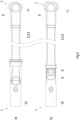
- Fig. 2 shows in two partial figures a) and b) a schematic plan view of a holder 1 according to the invention with inventive shapes of the first end 5.
- Partial figure a shows a complete holder 1, in which a core 3 with a covering 4 is arranged on a handle section 10.
- a core 3 with a covering 4 is arranged on a handle section 10.
- the first end 5 of the holder 1 is designed asymmetrically to the longitudinal axis of the holder 1, i.e. the area of the end 5 on one side of the longitudinal axis is larger than that on the opposite side.
- a circular through-opening 13 is provided in an axial end region of the holder 1, which is designed without a core 3. This through-opening 13 serves on the one hand to make the end region of the holder more flexible in order to be able to hold the mop cover better, and on the other hand it creates the possibility of hanging storage of the holder(s) 1 and also saves wrapping material.
- a mop cover 11 according to the invention, shown in dash-dotted lines, is mounted on this holder 1 and is elongated to correspond to the holder 1.
- the mop cover 11 preferably has a fiber material, in particular a microfiber material, on its wiping side, or consists entirely of this.
- the mop cover 11 stays on the holder because its material stretches over the holder 1 due to its flexibility.
- the clamping force is greatest in the area of the first end 5, but the holder 1 also has a holding effect over its axial length due to the static friction between the mop cover 11 and the casing 4. This applies even more strongly the stronger or more bends are introduced into the holder 1 by the user.
- the mop cover 11 is designed accordingly elongated, in particular as a hose closed on three sides. It is equipped with a The mop cover 11 is provided with a hand strap (not shown) sewn onto the holder 1 according to the invention, which makes it much easier to put it on the holder 1 according to the invention. A gripping area is provided on the opposite, closed end of the mop cover 11, which makes it easier to pull the mop cover 11 off the holder 1.
- the mop cover 11 is preferably pulled off intentionally in a curved pulling movement outside the longitudinal axis of the holder 1; accidental, unwanted pulling off during the wiping process is ruled out by the holding and friction forces between the holder 1 and the correspondingly shaped and elastically force-fitting mop cover 11.
- Partial figure b) shows a further embodiment of the first end 5 in the form of a more elongated, rather rectangular area formed symmetrically around the longitudinal axis.
- This embodiment of the holder 1 has a joint 9 between a handle section 10 and the holding section for the mop cover, which has a connecting section 8 with which it is either firmly or detachably connected to the joint 9. Due to the flexibility and dimensional stability of the core 3 after bending, such a joint 9 is not absolutely necessary, since the holder 1 can be bent into almost any required shape, including shapes that have multiple and possibly opposing bends. However, it is advantageous in order to make the handling of the invention even easier.
- This design with a holding section detachably connected to the joint has the advantage that a user can use differently designed holders depending on his cleaning task after exchanging them with the same handle.
- the invention makes it possible to use a holder that can be autoclaved several times to clean surfaces in clean rooms, thus complementing the surface cleaning devices known there, so that a cleaning specialist can use the same cleaning equipment for each cleaning location. cleanroom-compatible devices are available.
- the holder according to the invention can be bent at any point due to its coated core, even multiple times along its longitudinal axis, even in opposite directions, whereby the type and material of the core guarantee dimensional stability after bending and allow repeated bending at intervals without damage, embrittlement or the like. Due to its low manufacturing costs, the holder according to the invention is also economically viable as a disposable device, especially if it has no joint and the handle area is simply formed by an end section of the coated core, which is not covered by the mop cover when in use.
Landscapes
- Cleaning Implements For Floors, Carpets, Furniture, Walls, And The Like (AREA)
Description
- Die vorliegende Erfindung betrifft einen Halter für einen Wischbezug, wie er insbesondere in Reinräumen zur Reinigung von schwer zugänglichen Bereichen in Ecken, hinter oder zwischen Geräten und Einrichtungsgegenständen oder hoch oben an Wänden eingesetzt wird. Die Erfindung betrifft weiter einen zu diesem Halter passenden Wischbezug und eine Reinigungsvorrichtung aufweisend wenigstens einen Halter und einen auf dem Halter angeordneten Wischbezug.
- Neben der üblichen Flächenreinigung ist es insbesondere bei der gewerblichen Reinigung auch von klinischen, pharmazeutischen und weiteren Reinräumen erforderlich, die Oberflächen dort befindlicher Geräte, Einrichtungsgegenstände, Maschinen, etc. entsprechend den hohen Reinraum-Anforderungen zu reinigen. Hierzu werden insbesondere handgehaltene Halter eingesetzt, die im Vergleich zu Moppbezughaltern der Flächenreinigung deutlich schmaler und länger und vor allem auch weniger starr ausgebildet sind. Hierdurch können sie auch im Bogen hinter blockierende Gegenstände, in Spalten unter oder hinter diesen oder in sonstige, schwer zugängliche Bereiche geführt werden.
- Insbesondere im Bereich der gewerblichen Reinraumreinigung werden neben Einweg-Produkten auch Mehrwegprodukte eingesetzt, die nach einem Reinigungsvorgang entsprechend zum Wiedereinsatz aufbereitet werden müssen. Dies geschieht in erster Linie durch Autoklavieren.
- Die
DE 10 2016 121 251 A1 offenbart einen Moppbezughalter, bei dem zwei Klappflügel gelenkig an einem Mittelteil angeordnet sind und über die ein Moppbezug im Benutzungsfall gezogen wird. DieEP 2 534 994 A1 offenbart einen Moppbezughalter, bei dem mehrere Kisseneinlagen übereinander angeordnet sind. DieDE 198 33 553 C1 offenbart schließlich einen weiteren Moppbezughalter. - Die vorliegende Erfindung stellt sich daher die Aufgabe, einen für diesen Einsatzzweck besonders geeigneten und gut handhabbaren Halter anzugeben.
- Diese Aufgabe wird gelöst durch einen Halter für einen Wischbezug, aufweisend eine Seele aus einer Mehrzahl reversibel biegbarer, formstabiler Stränge oder einem flachen Materialband, wobei Stränge oder Materialband jeweils vollständig in eine Umhüllung eingebettet sind, weiter aufweisend ein erstes Ende und ein zweites Ende, wobei wenigstes das erste Ende einen Abschnitt aufweist, der querschnittsbreiter und/oder dicker als die den Abschnitt unmittelbar axial vorausgehende Umhüllung ausgebildet ist.
- Mit großem Vorteil ermöglicht die erfindungsgemäße Anordnung von mechanisch stabilen, vielfach reversibel biegsamen, dabei aber vor und nach einer Biegung formstabilen, zu einer Seele zusammengefasster Stränge oder ein, entsprechende Eigenschaften aufweisendes, flaches Materialband eine optimale Anpassbarkeit an den jeweiligen, wechselnden Einsatzort. Die erfindungsgemäße Seele ermöglicht Biegungen an beliebiger Stelle, eine Mehrzahl an Biegungen, auch in gegenläufiger Richtung und ein sehr breites Spektrum an Biegeradien. Diese Seelen aus Strängen haben gegenüber einer einteiligen Seele den großen Vorteil, in ihren mechanischen Eigenschaften optimal und einfach an die Einsatzbedingungen des sie aufweisenden Halters anpassbar zu sein, beispielsweise durch Wahl der Anzahl, des Durchmessers, des Abstandes zwischen einzelnen Strängen und des Materials der Stränge. Diese Stränge sind dabei bevorzugt aus einem Metall gefertigt, vorzugsweise als Draht ausgebildet. Mit erneut großem Vorteil sind die Stränge vollständig in eine Umhüllung eingebettet und damit vor Kontakt mit der Umgebung geschützt. Diese Umhüllung stellt gleichzeitig sicher, dass bei mehrfachen Biegungen in einem Strang möglicherweise aufgrund von Zug- und Druck- oder sogar Torsionskräften auftretende Mikrorisse kein Einfallstor für Verunreinigungen bilden, da diese möglicherweise vorhandenen Mikrorisse durch das Material der Umhüllung abgeschirmt sind. Gleiches gilt für die Ausgestaltung der Seele als flaches Materialband.
- Durch die Ausgestaltung wenigstens eines Endes des Halters mit einem Abschnitt, der querschnittsbreiter und/oder dicker als die den Abschnitt unmittelbar umgebende Umhüllung ausgebildet ist, ist auf einfachste Weise eine Halterung für einen Wischbezug geschaffen, der im Benutzungsfall über den erfindungsgemäßen Halter gezogen ist. Dieser Wischbezug liegt an diesem Abschnitt eng an, so eng, dass er bei Wischbewegungen nicht unbeabsichtigt vom Halter rutschen kann.
- In Ausgestaltung der Erfindung ist vorgesehen, dass die Stränge zueinander gleichorientiert angeordnet sind, insbesondere parallel zueinander, bevorzugt äquidistant parallel zueinander angeordnet sind. Erfindungsgemäß sind die Stränge in erster Linie als Runddrähte ausgebildet, können aber auch eine ovale, rechteckige oder andere Querschnittsfläche aufweisen. Die Stränge können erfindungsgemäß auch innerhalb der Umhüllung in zwei oder mehr Lagen übereinander angeordnet sein, wobei sich die einzelnen Stranglagen - aber auch die einzelnen Stränge - untereinander in ihren Eigenschaften unterscheiden dürfen. Sie können erfindungsgemäß auch in einer Mehrzahl, zueinander horizontal beabstandeter, vertikaler Reihen angeordnet sein, als zwei- oder dreidimensionale Gitterstruktur ausgebildet sein, solange die Stränge die gewünschte, formstabile Biegbarkeit des Halters ermöglichen.
- Sogar eine Seele in Form eines flachen Bandes aus insbesondere Metall ist erfindungsgemäß.
- Konstruktiv besonders einfach ist die erfindungsgemäße äquidistant parallele Anordnung der Stränge, die so auf einfache Weise nach Umspritzung oder Tauchung oder sonstigem Umhüllungsverfahren ein Endlosband aus Seele und Umhüllung ermöglichen, dass dann in den gewünschten Längen abgelängt und mit Endabschnitten versehen zu erfindungsgemäßen Haltern wird.
- Sind die Stränge aus einem anderen Material als die Umhüllung gebildet, so lassen sich die jeweiligen positiven Eigenschaften zweier Materialien mit Vorteil kombinieren. Grundsätzlich wäre auch ein Halter aus einem einzigen Material erfindungsgemäß, insbesondere dann, wenn dieses gleichermaßen dicke Stränge und deren dünne Umhüllung bilden kann. Das Material der Umhüllung ist in erster Linie erfindungsgemäß ein Kunststoff, der, insbesondere auch mehrfach, autoklavierfähig und dabei mehrfach ohne Rissbildung biegefähig ist. Erfindungsgemäß sind insbesondere Silikone oder thermoplastische Elastomere. Das Material der Stränge oder des flachen Materialbandes ist bevorzugt ein Metall, insbesondere ein Stahl oder Eisen, wobei aufgrund der Umhüllung mit großem Vorteil gegebenenfalls auf teuren Edelstahl verzichtet und günstigere Eisenmaterialien verwendet werden können. Besonders bevorzugt sind Kunststoffe mit Selbstheilungskräften, d.h. solche, die einer schnittartigen Beschädigung oder Rissbildung durch Schließen des Schnittes/Risses begegnen können.
- Ein solcher erfindungsgemäßer Halter ist in den je nach Reinigungsort und -bedingungen erforderlichen Breiten und Längen fertigbar, kann also von sehr lang und schmal bis hin zu kurz und breit ausgebildet sein, wobei der ebenfalls erfindungsgemäße Wischbezug dann diesen Umrissen entsprechend ausgebildet ist.
- In Ausgestaltung der Erfindung ist vorgesehen, dass auch das zweite Ende einen solchen Abschnitt aufweist und/oder der Abschnitt knochenformartig ausgebildet ist oder eine asymmetrisch zu einer Längsachse des Halters geformte Kontur aufweist. Um die Bedienung der Vorrichtung für einen Anwender möglichst einfach zu gestalten, sind die Enden so ausgeformt, dass sie aufgrund dieser Formgebung und der gewählten Maße einen aufgezogenen Wischbezug selbständig auch bei Krafteinwirkungen durch Wischbewegungen sicher halten, wodurch mit Vorteil auf gesonderte Haltevorrichtungen wie Druckknöpfe, Klettbänder und anders mehr der Wischbezüge auf dem Halter verzichtet werden kann. Die Haltewirkung beruht dabei in erster Linie auf einer Dehnung des Wischbezuges im Rahmen seines Elastizitätsmoduls durch den Halter, so dass dessen Gewebestruktur nicht gestört wird und beim Abziehen vom Halter der Wischbezug selbsttätig in seine Ausgangsform zurückgeht.
- Weist der erfindungsgemäße Halter eine Verbindungseinrichtung zur Verbindung mit einem Gelenk oder weist er selber ein Gelenk auf, insbesondere angeordnet an der Umhüllung, bevorzugt im Bereich des zweiten Endes, so ist er besonders beweglich, und auch an Verlängerungen anbringbar, wie einen Stiel.
- In Weiterbildung der Erfindung ist vorgesehen, dass er einen Griffabschnitt im Bereich des zweiten Endes aufweist. Diese Weiterbildung erspart den konstruktiven Aufwand eines Gelenkes, reduziert die Herstellungskosten und ist besonders für einen reinen handgehaltenen Einsatz in mittlerer Raumhöhe geeignet.
- Die Aufgabe der Erfindung wird auch durch einen Wischbezug gelöst, der eine zur Form des Halters wie beschrieben korrespondierende Form aufweist. Er ist entsprechend lang und schmal ausgebildet, insbesondere als dreiseitig geschlossener Schlauch. Diese Schlauchform ist erfindungsgemäß nahtlos, eine einseitige oder sogar eine umlaufende Naht sind jedoch erfindungsgemäß nicht ausgeschlossen. Durch seine Formgebung und sein elastisch spannendes Material ist er aus sich heraus haltend am Halter, insbesondere Kraftschlüssig durch radiale Spannkräfte des Wischbezugmaterials und axiale Reibungskräfte zwischen der inneren Oberfläche des Wischbezugs und der Oberfläche des Halters.
- Weist er eine Wischfläche aus einem Fasermaterial, insbesondere aus einem Mikrofasermaterial auf, so ist er besonders gut für den Einsatz in Reinräumen geeignet.
- Schließlich wird die Aufgabe der Erfindung auch durch eine Reinigungsvorrichtung gelöst, aufweisend wenigstens einen Halter wie beschrieben und einen, auf dem Halter angeordneten Wischbezug wie beschrieben.
- Die Erfindung wird nachfolgend anhand der Figuren der Zeichnung einiger Ausführungsbeispiele näher erläutert. Hierbei zeigen:
- Fig. 1:
- in vier Teilfiguren a) bis d) jeweils einen schematischen Querschnitt durch einen erfindungsgemäßen Halter und
- Fig. 2:
- eine schematische Aufsicht auf einen erfindungsgemäßen Halter mit mehreren erfindungsgemäßen Endenformen.
-
Fig. 1 zeigt in den Teilfiguren a) bis d) jeweils einen schematischen Querschnitt durch erfindungsgemäße Ausführungsformen von Seele 3 und deren Umhüllung 4 eines Halters 1. Zu erkennen ist in Teilfigur a) eine Ausführung mit acht, äquidistant zueinander in einer Ebene angeordneten, und durchmessergleichen Stahldrähten, umgeben von einer sie einschließenden Umhüllung aus einem Kunststoff, insbesondere einem autoklavierbaren, thermoplastischen Elastomer in Form eines Polyethylens, auch erhältlich unter der Bezeichnung Purell. - Die Teilfigur b) zeigt eine erfindungsgemäße Ausführungsform der Seele 3 mit drei, ebenfalls parallel zueinander orientierten, jedoch mit ihrer längeren Seite jeweils vertikal ausgerichteten, im Querschnitt rechteckigen Metallbändern als Seele 3. Diese sind entsprechend der in Teilfigur a) schematisch dargestellten Ausführungsform mit einer Umhüllung 4 umhüllt.
- Die Teilfigur c) zeigt in Aufsicht und Querschnitt eine weitere erfindungsgemäße Ausbildung der Seele 3, die hier als eine Gitternetzstruktur ausgebildet ist.
- Die Teilfigur d) zeigt eine weitere erfindungsgemäße Ausführungsform der Seele 3, die hier aus einem flachen Metallband gebildet ist.
- Die Umhüllung 4 in all diesen Ausführungsformen ist ausreichend dick ausgebildet, um die vollständig umschlossene Seele vor Umwelteinflüssen jeglicher Art zu schützen. Sie ist ebenfalls ausreichend dick, um kleineren Verletzungen der Oberfläche durch bspw. scharfe Gegenstände oder Kanten zu widerstehen, ohne dass diese bis zur jeweiligen Seele durchdringen könnten. Dabei ist sie jedoch nicht so dick ausgebildet, dass sie nicht wiederholt biegbar wäre.
-
Fig. 2 zeigt in zwei Teilfiguren a) und b) jeweils eine schematische Aufsicht auf einen erfindungsgemäßen Halter 1 mit erfindungsgemäßen Formen des ersten Endes 5. - Teilfigur a) zeigt einen vollständigen Halter 1, bei dem an einem Griffabschnitt 10 eine Seele 3 mit Umhüllung 4 angeordnet ist. Durch die Ausbildung der Seele als hier mehrere parallele Stränge gemäß
Fig. 1a ) ist er mit großem Vorteil in jede benötige Form bringbar, um auch schwer zugängliche Bereiche in einem zu reinigenden Raum zu erreichen. - Das erste Ende 5 des Halters 1 ist asymmetrisch zur Längsachse des Halters 1 ausgebildet, das heißt, die Fläche des Endes 5 auf einer Seite der Längsachse ist größer als diejenige auf der gegenüberliegenden Seite. Eine kreisförmige Durchgangsöffnung 13 ist in einem axialen Endbereich des Halters 1 vorgesehen, der ohne Seele 3 ausgebildet ist. Diese Durchgangsöffnung 13 dient zum einen dazu, den Endbereich des Halters flexibler zu gestalten, um so den Wischbezug besser halten zu können, zum anderen ist so eine Möglichkeit zu einer hängenden Lagerung des oder der Halter 1 geschaffen und auch Umhüllungsmaterial eingespart.
- Das Ende 5 wird dabei auf den zuvor in Endlosform und dann abgelängten Strang aus Seele 3 und Umhüllung 4 aufgespritzt. Dies erhöht die Fertigungseffizienz bei gleichzeitiger Reduktion der Kosten. Aufgezogen auf diesen Halter 1 ist ein strichpunktiert dargestellter, erfindungsgemäßer Wischbezug 11, der korrespondierend zum Halter 1 länglich ausgebildet ist. Der Wischbezug 11 weist dabei bevorzugt auf seiner Wischseite ein Fasermaterial, insbesondere ein Mikrofasermaterial auf, bzw. besteht gänzlich aus diesem. Der Wischbezug 11 hält auf dem Halter, da sich sein Material wegen seiner Flexibilität über den Halter 1 spannt. Hierbei ist die Spannkraft am größten im Bereich des ersten Endes 5, der Halter 1 wirkt jedoch auch über seine axiale Länge aufgrund der Haftreibung zwischen Wischbezug 11 und Umhüllung 4 haltend. Dies gilt umso stärker, je stärkere oder mehrere Biegungen im Halter 1 durch den Benutzer eingebracht sind.
- Der Wischbezug 11 ist entsprechend länglich ausgebildet, insbesondere als dreiseitig geschlossener Schlauch. Er ist mit einer im griffnahen Bereich angenähten, nicht dargestellten, Handschlaufe versehen, die das Aufziehen auf den erfindungsgemäßen Halter 1 wesentlich erleichtert. Am gegenüberliegenden, geschlossenen Ende des Wischbezuges 11 ist ein Anfassbereich vorgesehen, der das Abziehen des Wischbezuges 11 vom Halter 1 erleichtert. Das gewollte Abziehen des Wischbezuges 11 erfolgt bevorzugt in einer kurvenförmigen Auszugsbewegung außerhalb der Längsachse des Halters 1, ein versehentliches, ungewolltes Abziehen beim Wischvorgang ist durch die Halte- und Reibekräfte zwischen Halter 1 und entsprechend geformten und elastisch kraftschlüssig anliegendem Wischbezug 11 ausgeschlossen.
- Teilfigur b) zeigt eine weitere Ausführungsform des ersten Endes 5 in Form eines symmetrisch um die Längsachse angeformten länglicheren, eher rechteckigen Bereich. Diese Ausführungsform des Halters 1 weist ein Gelenk 9 zwischen einem Griffabschnitt 10 und dem Halteabschnitt für den Wischbezug auf, der einen Verbindungsabschnitt 8 aufweist, mit dem er entweder fest oder lösbar mit dem Gelenk 9 verbunden ist. Aufgrund der Biegsamkeit und der Formstabilität der Seele 3 nach Biegung ist ein solches Gelenk 9 nicht zwingend erforderlich, da der Halter 1 in fast jede erforderliche Form gebogen werden kann, inklusiver solcher Formen, die mehrfache und ggf. auch gegenläufige Biegungen aufweisen. Es ist jedoch vorteilhaft, um die Handhabung der Erfindung noch weiter zu erleichtern. Diese Ausgestaltung mit einem lösbar mit dem Gelenk verbundenen Halteabschnitt hat den Vorteil, dass ein Anwender je nach seiner Reinigungsaufgabe unterschiedlich ausgebildete Halter nach Austausch mit demselben Griffstück einsetzen kann.
- Mit großem Vorteil ermöglicht die Erfindung den Einsatz eines auch mehrfach autoklavierbaren Halters zur Reinigung von Oberflächen in Reinräumen und ergänzt so die dort bekannten Flächenreinigungsgeräte, so dass einer Reinigungsfachkraft für jeden Reinigungsort reinraumtaugliche Geräte zur Verfügung stehen. Der erfindungsgemäße Halter ist dabei aufgrund seiner umhüllten Seele an beliebiger Stelle biegbar, auch mehrfach entlang seiner Längsachse, auch in gegenläufiger Biegung, wobei Art und Material der Seele eine Formstabilität nach Biegung gewährleisten und in zeitlichen Abständen wiederholte Biegungen ohne Beschädigungen, Versprödungen oder dergleichen zulassen. Der erfindungsgemäße Halter ist dabei aufgrund seiner günstigen Herstellkosten auch wirtschaftlich sinnvoll als Einmalgerät einsetzbar, insbesondere dann, wenn er kein Gelenk aufweist und der Griffbereich einfach durch einen Endabschnitt der umhüllten Seele gebildet ist, die vom Wischbezug im Benutzungsfall nicht überdeckt ist.
-
- 1
- Halter
- 2
- Seele
- 3
- Strang
- 4
- Umhüllung
- 5
- erstes Ende
- 6
- zweites Ende
- 7
- Abschnitt
- 8
- Verbindungseinrichtung
- 9
- Gelenk
- 10
- Griffabschnitt
- 11
- Wischbezug
- 12
- Reinigungsvorrichtung
- 13
- Durchgangsöffnung
Claims (9)
- Halter (1) für ein Wischbezug, dadurch gekennzeichnet, dass er eine Seele (2) aus einer Mehrzahl reversibel biegbarer, formstabiler Stränge (3) oder einem flachen Materialband aufweist, wobei Stränge (3) oder Materialband jeweils vollständig in eine Umhüllung (4) eingebettet sind, weiter aufweisend ein erstes Ende (5) und ein zweites Ende (6), wobei wenigstes das erste Ende (5) einen Abschnitt (7) aufweist, der querschnittsbreiter und/oder dicker als die den Abschnitt (7) unmittelbar axial vorausgehende Umhüllung (4) ausgebildet ist.
- Halter (1) gemäß Anspruch 1, dadurch gekennzeichnet, dass die Stränge (3) zueinander gleichorientiert angeordnet sind, insbesondere parallel zueinander, bevorzugt äquidistant parallel zueinander angeordnet sind.
- Halter (1) gemäß Anspruch 1 oder 2, dadurch gekennzeichnet, dass die Stränge (3) aus einem anderen Material als die Umhüllung (4) gebildet sind und/oder das Material der Umhüllung autoklavierfähig ist.
- Halter (1) gemäß einem der vorhergehenden Ansprüche, dadurch gekennzeichnet, dass auch das zweite Ende (6) einen solchen Abschnitt (7) aufweist und/oder der Abschnitt (7) knochenformartig ausgebildet ist oder eine asymmetrisch zu einer Längsachse des Halters (1) geformte Kontur aufweist.
- Halter (1) gemäß einem der vorhergehenden Ansprüche, dadurch gekennzeichnet, dass er eine Verbindungseinrichtung (8) zur Verbindung mit einem Gelenk oder selber ein Gelenk (9) aufweist, insbesondere angeordnet an der Umhüllung (4), bevorzugt im Bereich des zweiten Endes (6).
- Halter (1) gemäß einem der vorhergehenden Ansprüche, dadurch gekennzeichnet, dass er einen Griffabschnitt (10) im Bereich des zweiten Endes (6) aufweist.
- Wischbezug (11), dadurch gekennzeichnet, dass er eine zur Form des Halters (1) gemäß einem der Ansprüche 1 bis 6 korrespondierende Form aufweist.
- Wischbezug (11) gemäß Anspruch 7, dadurch gekennzeichnet, dass er eine Wischfläche (12) aus einem Fasermaterial aufweist, vorzugsweise einem Mikrofasermaterial.
- Reinigungsvorrichtung (12) aufweisend wenigstens einen Halter (1) gemäß einem der Ansprüche 1 bis 6 und einen, auf dem Halter (1) angeordneten, Wischbezug (11) gemäß einem der Ansprüche 7 oder 8.
Applications Claiming Priority (1)
| Application Number | Priority Date | Filing Date | Title |
|---|---|---|---|
| DE102021104030.2A DE102021104030A1 (de) | 2021-02-19 | 2021-02-19 | Halter für einen Wischbezug, Wischbezug und Reinigungsvorrichtung |
Publications (2)
| Publication Number | Publication Date |
|---|---|
| EP4046558A1 EP4046558A1 (de) | 2022-08-24 |
| EP4046558B1 true EP4046558B1 (de) | 2024-05-08 |
Family
ID=80445691
Family Applications (1)
| Application Number | Title | Priority Date | Filing Date |
|---|---|---|---|
| EP22155561.8A Active EP4046558B1 (de) | 2021-02-19 | 2022-02-08 | Halter für einen wischbezug, wischbezug und reinigungsvorrichtung |
Country Status (4)
| Country | Link |
|---|---|
| US (1) | US20220265114A1 (de) |
| EP (1) | EP4046558B1 (de) |
| CN (1) | CN114947669B (de) |
| DE (1) | DE102021104030A1 (de) |
Family Cites Families (18)
| Publication number | Priority date | Publication date | Assignee | Title |
|---|---|---|---|---|
| US2185873A (en) * | 1938-04-27 | 1940-01-02 | Joseph A Underhill | Dust mop |
| US5044040A (en) | 1990-05-17 | 1991-09-03 | Lise Tetrault | Toiletting assist device |
| DE19833553C1 (de) * | 1998-07-24 | 1999-12-30 | Freudenberg Carl Fa | Mop |
| US20060168749A1 (en) * | 2005-02-01 | 2006-08-03 | Jone Chang | Bendable bathing scrubber |
| US7392564B1 (en) | 2006-04-05 | 2008-07-01 | Dotworkz | Dome cleaning device |
| JP5115484B2 (ja) * | 2009-01-19 | 2013-01-09 | 市光工業株式会社 | ワイパーブレード |
| JP5271787B2 (ja) * | 2009-04-22 | 2013-08-21 | 株式会社ニトムズ | 清掃装置 |
| KR101369025B1 (ko) * | 2010-02-12 | 2014-02-28 | 카오카부시키가이샤 | 파이프의 연결 구조 및 청소구 |
| US8745808B2 (en) | 2010-04-13 | 2014-06-10 | Specialty Products Of Greenwood, Missouri, Inc. | Applicator with individually flexible pad support fingers |
| US10952587B2 (en) * | 2010-04-16 | 2021-03-23 | Unger Marketing International, Llc | Dusting devices |
| JP5964569B2 (ja) * | 2011-10-04 | 2016-08-03 | 株式会社テラモト | 清掃具用のホルダ、および清掃具 |
| DE102012022127A1 (de) | 2012-09-17 | 2014-03-20 | Carl Freudenberg Kg | Mopp mit einem Wischbezug |
| US20140137352A1 (en) * | 2012-11-10 | 2014-05-22 | Lydia K Golla | Multipurpose Bendable Tool |
| CN204276391U (zh) * | 2014-06-30 | 2015-04-22 | 苏州巨洁电子有限公司 | Ccd模组清洁用柔性无尘棉签 |
| CN205292568U (zh) * | 2016-01-08 | 2016-06-08 | 宁波亿拍客网络科技有限公司 | 一种自适应清洁器 |
| DE102016121251B4 (de) * | 2016-11-07 | 2018-07-12 | Pfennig Reinigungstechnik Gmbh | Moppbezughalter |
| US11744432B1 (en) * | 2019-05-06 | 2023-09-05 | Contec Inc. | Adjustable dusting tool and related method |
| JP3226166U (ja) * | 2020-01-10 | 2020-05-07 | 株式会社ソフト99コーポレーション | 水滴拭き取り具 |
-
2021
- 2021-02-19 DE DE102021104030.2A patent/DE102021104030A1/de not_active Ceased
-
2022
- 2022-02-08 EP EP22155561.8A patent/EP4046558B1/de active Active
- 2022-02-16 CN CN202210143236.5A patent/CN114947669B/zh active Active
- 2022-02-17 US US17/673,908 patent/US20220265114A1/en active Pending
Also Published As
| Publication number | Publication date |
|---|---|
| CN114947669B (zh) | 2025-01-17 |
| DE102021104030A1 (de) | 2022-09-08 |
| US20220265114A1 (en) | 2022-08-25 |
| CN114947669A (zh) | 2022-08-30 |
| EP4046558A1 (de) | 2022-08-24 |
Similar Documents
| Publication | Publication Date | Title |
|---|---|---|
| EP2471409B1 (de) | Applikatoreinrichtung, insbesondere für einen Kosmetikapplikator | |
| DE112010001295T5 (de) | Langstruktur für bewegliches Teil | |
| DE112008002196T5 (de) | Abschirmleiter | |
| EP2775184B1 (de) | Sanitärschlauch mit einem Innenschlauch und einer Ummantelung | |
| DE102018110105A1 (de) | Zange | |
| DE102011106152A1 (de) | Deformationselement einer Kraftfahrzeug-Karosserie | |
| EP3723928B1 (de) | Schneidgerät zum ablängen von wellrohren sowie führungsvorsprünge in einem solchen schneidgerät | |
| EP4046558A1 (de) | Halter für einen wischbezug, wischbezug und reinigungsvorrichtung | |
| DE102009043454A1 (de) | Rillschlauchspannvorrichtung | |
| DE202013104300U1 (de) | Ziehharmonika-Applikator | |
| EP3764943B1 (de) | Interdentalreiniger | |
| EP0017861B1 (de) | Zahnärztliches Handstück | |
| DE102010005580A1 (de) | Schneidwerkzeug mit kegelstumpfförmigen Schneidelementen | |
| DE102021002202A1 (de) | Flexibler schlauch, insbesondere staubsaugerschlauch | |
| DE112020005643T5 (de) | Kabelbaum | |
| DE102005027591B4 (de) | Abstandshalter | |
| EP2477519B1 (de) | Reinigungsbürste | |
| DE3623702A1 (de) | Biegbarer schlauch mit zueinander parallelen, ringfoermigen wellen und axialabstuetzung | |
| DE1660612A1 (de) | Verfahren und Vorrichtung zum Herstellen von Faeden mit Sonderquerschnitt sowie die hiermit hergestellten Faeden | |
| DE1440237A1 (de) | Kabelfuehrungskanal | |
| DE102004041452A1 (de) | Elektrische Leitung | |
| DE60027238T2 (de) | Drahtarmierung für elastomere oder plastomere Profile und Verfahren zur deren Herstellung | |
| DE112023001701T5 (de) | Kabelbaum | |
| AT399548B (de) | Mehrfachrohr | |
| EP1859521A1 (de) | Rohr |
Legal Events
| Date | Code | Title | Description |
|---|---|---|---|
| PUAI | Public reference made under article 153(3) epc to a published international application that has entered the european phase |
Free format text: ORIGINAL CODE: 0009012 |
|
| STAA | Information on the status of an ep patent application or granted ep patent |
Free format text: STATUS: THE APPLICATION HAS BEEN PUBLISHED |
|
| AK | Designated contracting states |
Kind code of ref document: A1 Designated state(s): AL AT BE BG CH CY CZ DE DK EE ES FI FR GB GR HR HU IE IS IT LI LT LU LV MC MK MT NL NO PL PT RO RS SE SI SK SM TR |
|
| STAA | Information on the status of an ep patent application or granted ep patent |
Free format text: STATUS: REQUEST FOR EXAMINATION WAS MADE |
|
| 17P | Request for examination filed |
Effective date: 20230224 |
|
| RBV | Designated contracting states (corrected) |
Designated state(s): AL AT BE BG CH CY CZ DE DK EE ES FI FR GB GR HR HU IE IS IT LI LT LU LV MC MK MT NL NO PL PT RO RS SE SI SK SM TR |
|
| GRAP | Despatch of communication of intention to grant a patent |
Free format text: ORIGINAL CODE: EPIDOSNIGR1 |
|
| STAA | Information on the status of an ep patent application or granted ep patent |
Free format text: STATUS: GRANT OF PATENT IS INTENDED |
|
| RIC1 | Information provided on ipc code assigned before grant |
Ipc: A47L 13/254 20060101ALI20240116BHEP Ipc: A47L 13/24 20060101AFI20240116BHEP |
|
| INTG | Intention to grant announced |
Effective date: 20240201 |
|
| GRAS | Grant fee paid |
Free format text: ORIGINAL CODE: EPIDOSNIGR3 |
|
| GRAA | (expected) grant |
Free format text: ORIGINAL CODE: 0009210 |
|
| STAA | Information on the status of an ep patent application or granted ep patent |
Free format text: STATUS: THE PATENT HAS BEEN GRANTED |
|
| AK | Designated contracting states |
Kind code of ref document: B1 Designated state(s): AL AT BE BG CH CY CZ DE DK EE ES FI FR GB GR HR HU IE IS IT LI LT LU LV MC MK MT NL NO PL PT RO RS SE SI SK SM TR |
|
| REG | Reference to a national code |
Ref country code: GB Ref legal event code: FG4D Free format text: NOT ENGLISH |
|
| REG | Reference to a national code |
Ref country code: CH Ref legal event code: EP |
|
| REG | Reference to a national code |
Ref country code: DE Ref legal event code: R096 Ref document number: 502022000852 Country of ref document: DE |
|
| REG | Reference to a national code |
Ref country code: IE Ref legal event code: FG4D Free format text: LANGUAGE OF EP DOCUMENT: GERMAN |
|
| P01 | Opt-out of the competence of the unified patent court (upc) registered |
Effective date: 20240523 |
|
| REG | Reference to a national code |
Ref country code: LT Ref legal event code: MG9D |
|
| REG | Reference to a national code |
Ref country code: NL Ref legal event code: MP Effective date: 20240508 |
|
| PG25 | Lapsed in a contracting state [announced via postgrant information from national office to epo] |
Ref country code: IS Free format text: LAPSE BECAUSE OF FAILURE TO SUBMIT A TRANSLATION OF THE DESCRIPTION OR TO PAY THE FEE WITHIN THE PRESCRIBED TIME-LIMIT Effective date: 20240908 |
|
| PG25 | Lapsed in a contracting state [announced via postgrant information from national office to epo] |
Ref country code: BG Free format text: LAPSE BECAUSE OF FAILURE TO SUBMIT A TRANSLATION OF THE DESCRIPTION OR TO PAY THE FEE WITHIN THE PRESCRIBED TIME-LIMIT Effective date: 20240508 |
|
| PG25 | Lapsed in a contracting state [announced via postgrant information from national office to epo] |
Ref country code: HR Free format text: LAPSE BECAUSE OF FAILURE TO SUBMIT A TRANSLATION OF THE DESCRIPTION OR TO PAY THE FEE WITHIN THE PRESCRIBED TIME-LIMIT Effective date: 20240508 Ref country code: FI Free format text: LAPSE BECAUSE OF FAILURE TO SUBMIT A TRANSLATION OF THE DESCRIPTION OR TO PAY THE FEE WITHIN THE PRESCRIBED TIME-LIMIT Effective date: 20240508 |
|
| PG25 | Lapsed in a contracting state [announced via postgrant information from national office to epo] |
Ref country code: GR Free format text: LAPSE BECAUSE OF FAILURE TO SUBMIT A TRANSLATION OF THE DESCRIPTION OR TO PAY THE FEE WITHIN THE PRESCRIBED TIME-LIMIT Effective date: 20240809 |
|
| PG25 | Lapsed in a contracting state [announced via postgrant information from national office to epo] |
Ref country code: PT Free format text: LAPSE BECAUSE OF FAILURE TO SUBMIT A TRANSLATION OF THE DESCRIPTION OR TO PAY THE FEE WITHIN THE PRESCRIBED TIME-LIMIT Effective date: 20240909 |
|
| PG25 | Lapsed in a contracting state [announced via postgrant information from national office to epo] |
Ref country code: NL Free format text: LAPSE BECAUSE OF FAILURE TO SUBMIT A TRANSLATION OF THE DESCRIPTION OR TO PAY THE FEE WITHIN THE PRESCRIBED TIME-LIMIT Effective date: 20240508 |
|
| PG25 | Lapsed in a contracting state [announced via postgrant information from national office to epo] |
Ref country code: ES Free format text: LAPSE BECAUSE OF FAILURE TO SUBMIT A TRANSLATION OF THE DESCRIPTION OR TO PAY THE FEE WITHIN THE PRESCRIBED TIME-LIMIT Effective date: 20240508 |
|
| PG25 | Lapsed in a contracting state [announced via postgrant information from national office to epo] |
Ref country code: PL Free format text: LAPSE BECAUSE OF FAILURE TO SUBMIT A TRANSLATION OF THE DESCRIPTION OR TO PAY THE FEE WITHIN THE PRESCRIBED TIME-LIMIT Effective date: 20240508 |
|
| PG25 | Lapsed in a contracting state [announced via postgrant information from national office to epo] |
Ref country code: LV Free format text: LAPSE BECAUSE OF FAILURE TO SUBMIT A TRANSLATION OF THE DESCRIPTION OR TO PAY THE FEE WITHIN THE PRESCRIBED TIME-LIMIT Effective date: 20240508 |
|
| PG25 | Lapsed in a contracting state [announced via postgrant information from national office to epo] |
Ref country code: PT Free format text: LAPSE BECAUSE OF FAILURE TO SUBMIT A TRANSLATION OF THE DESCRIPTION OR TO PAY THE FEE WITHIN THE PRESCRIBED TIME-LIMIT Effective date: 20240909 Ref country code: PL Free format text: LAPSE BECAUSE OF FAILURE TO SUBMIT A TRANSLATION OF THE DESCRIPTION OR TO PAY THE FEE WITHIN THE PRESCRIBED TIME-LIMIT Effective date: 20240508 Ref country code: NO Free format text: LAPSE BECAUSE OF FAILURE TO SUBMIT A TRANSLATION OF THE DESCRIPTION OR TO PAY THE FEE WITHIN THE PRESCRIBED TIME-LIMIT Effective date: 20240808 Ref country code: NL Free format text: LAPSE BECAUSE OF FAILURE TO SUBMIT A TRANSLATION OF THE DESCRIPTION OR TO PAY THE FEE WITHIN THE PRESCRIBED TIME-LIMIT Effective date: 20240508 Ref country code: LV Free format text: LAPSE BECAUSE OF FAILURE TO SUBMIT A TRANSLATION OF THE DESCRIPTION OR TO PAY THE FEE WITHIN THE PRESCRIBED TIME-LIMIT Effective date: 20240508 Ref country code: IS Free format text: LAPSE BECAUSE OF FAILURE TO SUBMIT A TRANSLATION OF THE DESCRIPTION OR TO PAY THE FEE WITHIN THE PRESCRIBED TIME-LIMIT Effective date: 20240908 Ref country code: HR Free format text: LAPSE BECAUSE OF FAILURE TO SUBMIT A TRANSLATION OF THE DESCRIPTION OR TO PAY THE FEE WITHIN THE PRESCRIBED TIME-LIMIT Effective date: 20240508 Ref country code: GR Free format text: LAPSE BECAUSE OF FAILURE TO SUBMIT A TRANSLATION OF THE DESCRIPTION OR TO PAY THE FEE WITHIN THE PRESCRIBED TIME-LIMIT Effective date: 20240809 Ref country code: FI Free format text: LAPSE BECAUSE OF FAILURE TO SUBMIT A TRANSLATION OF THE DESCRIPTION OR TO PAY THE FEE WITHIN THE PRESCRIBED TIME-LIMIT Effective date: 20240508 Ref country code: ES Free format text: LAPSE BECAUSE OF FAILURE TO SUBMIT A TRANSLATION OF THE DESCRIPTION OR TO PAY THE FEE WITHIN THE PRESCRIBED TIME-LIMIT Effective date: 20240508 Ref country code: BG Free format text: LAPSE BECAUSE OF FAILURE TO SUBMIT A TRANSLATION OF THE DESCRIPTION OR TO PAY THE FEE WITHIN THE PRESCRIBED TIME-LIMIT Effective date: 20240508 Ref country code: RS Free format text: LAPSE BECAUSE OF FAILURE TO SUBMIT A TRANSLATION OF THE DESCRIPTION OR TO PAY THE FEE WITHIN THE PRESCRIBED TIME-LIMIT Effective date: 20240808 |
|
| PG25 | Lapsed in a contracting state [announced via postgrant information from national office to epo] |
Ref country code: DK Free format text: LAPSE BECAUSE OF FAILURE TO SUBMIT A TRANSLATION OF THE DESCRIPTION OR TO PAY THE FEE WITHIN THE PRESCRIBED TIME-LIMIT Effective date: 20240508 |
|
| PG25 | Lapsed in a contracting state [announced via postgrant information from national office to epo] |
Ref country code: EE Free format text: LAPSE BECAUSE OF FAILURE TO SUBMIT A TRANSLATION OF THE DESCRIPTION OR TO PAY THE FEE WITHIN THE PRESCRIBED TIME-LIMIT Effective date: 20240508 |
|
| PG25 | Lapsed in a contracting state [announced via postgrant information from national office to epo] |
Ref country code: CZ Free format text: LAPSE BECAUSE OF FAILURE TO SUBMIT A TRANSLATION OF THE DESCRIPTION OR TO PAY THE FEE WITHIN THE PRESCRIBED TIME-LIMIT Effective date: 20240508 |
|
| PG25 | Lapsed in a contracting state [announced via postgrant information from national office to epo] |
Ref country code: SK Free format text: LAPSE BECAUSE OF FAILURE TO SUBMIT A TRANSLATION OF THE DESCRIPTION OR TO PAY THE FEE WITHIN THE PRESCRIBED TIME-LIMIT Effective date: 20240508 Ref country code: RO Free format text: LAPSE BECAUSE OF FAILURE TO SUBMIT A TRANSLATION OF THE DESCRIPTION OR TO PAY THE FEE WITHIN THE PRESCRIBED TIME-LIMIT Effective date: 20240508 |
|
| PG25 | Lapsed in a contracting state [announced via postgrant information from national office to epo] |
Ref country code: SM Free format text: LAPSE BECAUSE OF FAILURE TO SUBMIT A TRANSLATION OF THE DESCRIPTION OR TO PAY THE FEE WITHIN THE PRESCRIBED TIME-LIMIT Effective date: 20240508 |
|
| PG25 | Lapsed in a contracting state [announced via postgrant information from national office to epo] |
Ref country code: SM Free format text: LAPSE BECAUSE OF FAILURE TO SUBMIT A TRANSLATION OF THE DESCRIPTION OR TO PAY THE FEE WITHIN THE PRESCRIBED TIME-LIMIT Effective date: 20240508 Ref country code: SK Free format text: LAPSE BECAUSE OF FAILURE TO SUBMIT A TRANSLATION OF THE DESCRIPTION OR TO PAY THE FEE WITHIN THE PRESCRIBED TIME-LIMIT Effective date: 20240508 Ref country code: RO Free format text: LAPSE BECAUSE OF FAILURE TO SUBMIT A TRANSLATION OF THE DESCRIPTION OR TO PAY THE FEE WITHIN THE PRESCRIBED TIME-LIMIT Effective date: 20240508 Ref country code: EE Free format text: LAPSE BECAUSE OF FAILURE TO SUBMIT A TRANSLATION OF THE DESCRIPTION OR TO PAY THE FEE WITHIN THE PRESCRIBED TIME-LIMIT Effective date: 20240508 Ref country code: DK Free format text: LAPSE BECAUSE OF FAILURE TO SUBMIT A TRANSLATION OF THE DESCRIPTION OR TO PAY THE FEE WITHIN THE PRESCRIBED TIME-LIMIT Effective date: 20240508 Ref country code: CZ Free format text: LAPSE BECAUSE OF FAILURE TO SUBMIT A TRANSLATION OF THE DESCRIPTION OR TO PAY THE FEE WITHIN THE PRESCRIBED TIME-LIMIT Effective date: 20240508 |
|
| REG | Reference to a national code |
Ref country code: DE Ref legal event code: R097 Ref document number: 502022000852 Country of ref document: DE |
|
| PLBE | No opposition filed within time limit |
Free format text: ORIGINAL CODE: 0009261 |
|
| STAA | Information on the status of an ep patent application or granted ep patent |
Free format text: STATUS: NO OPPOSITION FILED WITHIN TIME LIMIT |
|
| 26N | No opposition filed |
Effective date: 20250211 |
|
| PG25 | Lapsed in a contracting state [announced via postgrant information from national office to epo] |
Ref country code: SI Free format text: LAPSE BECAUSE OF FAILURE TO SUBMIT A TRANSLATION OF THE DESCRIPTION OR TO PAY THE FEE WITHIN THE PRESCRIBED TIME-LIMIT Effective date: 20240508 |
|
| PG25 | Lapsed in a contracting state [announced via postgrant information from national office to epo] |
Ref country code: SE Free format text: LAPSE BECAUSE OF FAILURE TO SUBMIT A TRANSLATION OF THE DESCRIPTION OR TO PAY THE FEE WITHIN THE PRESCRIBED TIME-LIMIT Effective date: 20240508 |
|
| PG25 | Lapsed in a contracting state [announced via postgrant information from national office to epo] |
Ref country code: MC Free format text: LAPSE BECAUSE OF FAILURE TO SUBMIT A TRANSLATION OF THE DESCRIPTION OR TO PAY THE FEE WITHIN THE PRESCRIBED TIME-LIMIT Effective date: 20240508 |
|
| PG25 | Lapsed in a contracting state [announced via postgrant information from national office to epo] |
Ref country code: LU Free format text: LAPSE BECAUSE OF NON-PAYMENT OF DUE FEES Effective date: 20250208 |
|
| PG25 | Lapsed in a contracting state [announced via postgrant information from national office to epo] |
Ref country code: IE Free format text: LAPSE BECAUSE OF NON-PAYMENT OF DUE FEES Effective date: 20250208 |
|
| REG | Reference to a national code |
Ref country code: CH Ref legal event code: U11 Free format text: ST27 STATUS EVENT CODE: U-0-0-U10-U11 (AS PROVIDED BY THE NATIONAL OFFICE) Effective date: 20260301 |
|
| PGFP | Annual fee paid to national office [announced via postgrant information from national office to epo] |
Ref country code: GB Payment date: 20260219 Year of fee payment: 5 |
|
| PGFP | Annual fee paid to national office [announced via postgrant information from national office to epo] |
Ref country code: DE Payment date: 20260217 Year of fee payment: 5 |
|
| PGFP | Annual fee paid to national office [announced via postgrant information from national office to epo] |
Ref country code: AT Payment date: 20260301 Year of fee payment: 5 |
|
| PGFP | Annual fee paid to national office [announced via postgrant information from national office to epo] |
Ref country code: BE Payment date: 20260218 Year of fee payment: 5 Ref country code: IT Payment date: 20260227 Year of fee payment: 5 |
|
| PGFP | Annual fee paid to national office [announced via postgrant information from national office to epo] |
Ref country code: FR Payment date: 20260223 Year of fee payment: 5 |
|
| PGFP | Annual fee paid to national office [announced via postgrant information from national office to epo] |
Ref country code: CH Payment date: 20260301 Year of fee payment: 5 |