EP4046524B1 - Gewirkte verschlussleiste, reissverschluss und verfahren zum herstellen der gewirkten verschlussleiste - Google Patents
Gewirkte verschlussleiste, reissverschluss und verfahren zum herstellen der gewirkten verschlussleiste Download PDFInfo
- Publication number
- EP4046524B1 EP4046524B1 EP19948957.6A EP19948957A EP4046524B1 EP 4046524 B1 EP4046524 B1 EP 4046524B1 EP 19948957 A EP19948957 A EP 19948957A EP 4046524 B1 EP4046524 B1 EP 4046524B1
- Authority
- EP
- European Patent Office
- Prior art keywords
- fastener
- tape
- knitted
- wale
- yarn
- Prior art date
- Legal status (The legal status is an assumption and is not a legal conclusion. Google has not performed a legal analysis and makes no representation as to the accuracy of the status listed.)
- Active
Links
Images

Classifications
-
- A—HUMAN NECESSITIES
- A44—HABERDASHERY; JEWELLERY
- A44B—BUTTONS, PINS, BUCKLES, SLIDE FASTENERS, OR THE LIKE
- A44B19/00—Slide fasteners
- A44B19/24—Details
- A44B19/34—Stringer tapes; Flaps secured to stringers for covering the interlocking members
- A44B19/343—Knitted stringer tapes
-
- A—HUMAN NECESSITIES
- A44—HABERDASHERY; JEWELLERY
- A44B—BUTTONS, PINS, BUCKLES, SLIDE FASTENERS, OR THE LIKE
- A44B19/00—Slide fasteners
- A44B19/42—Making by processes not fully provided for in one other class, e.g. B21D53/50, B21F45/18, B22D17/16, B29D5/00
- A44B19/52—Securing the interlocking members to stringer tapes while making the latter
- A44B19/56—Securing the interlocking members to stringer tapes while making the latter while knitting the stringer tapes
-
- D—TEXTILES; PAPER
- D04—BRAIDING; LACE-MAKING; KNITTING; TRIMMINGS; NON-WOVEN FABRICS
- D04B—KNITTING
- D04B21/00—Warp knitting processes for the production of fabrics or articles not dependent on the use of particular machines; Fabrics or articles defined by such processes
- D04B21/14—Fabrics characterised by the incorporation by knitting, in one or more thread, fleece, or fabric layers, of reinforcing, binding, or decorative threads; Fabrics incorporating small auxiliary elements, e.g. for decorative purposes
- D04B21/16—Fabrics characterised by the incorporation by knitting, in one or more thread, fleece, or fabric layers, of reinforcing, binding, or decorative threads; Fabrics incorporating small auxiliary elements, e.g. for decorative purposes incorporating synthetic threads
-
- D—TEXTILES; PAPER
- D10—INDEXING SCHEME ASSOCIATED WITH SUBLASSES OF SECTION D, RELATING TO TEXTILES
- D10B—INDEXING SCHEME ASSOCIATED WITH SUBLASSES OF SECTION D, RELATING TO TEXTILES
- D10B2403/00—Details of fabric structure established in the fabric forming process
- D10B2403/01—Surface features
- D10B2403/011—Dissimilar front and back faces
- D10B2403/0112—One smooth surface, e.g. laminated or coated
-
- D—TEXTILES; PAPER
- D10—INDEXING SCHEME ASSOCIATED WITH SUBLASSES OF SECTION D, RELATING TO TEXTILES
- D10B—INDEXING SCHEME ASSOCIATED WITH SUBLASSES OF SECTION D, RELATING TO TEXTILES
- D10B2501/00—Wearing apparel
- D10B2501/06—Details of garments
- D10B2501/063—Fasteners
- D10B2501/0631—Slide fasteners
Definitions
- the present invention relates to a knitted fastener stringer of which fastener elements are knitted in a fastener tape, a fastener chain including the knitted fastener stringer, and a method for manufacturing the knitted fastener stringer.
- a knitted fastener stringer is known as one of fastener stringers for slide fasteners.
- a knitted fastener stringer a continuous plurality of fastener elements formed of monofilament made of synthetic resin are knitted in a tape side edge portion of a fastener tape.
- a portion of the fastener tape in which the fastener elements are knitted is called an element attaching portion.
- a knitted fastener stringer is manufactured, for example, using a double warp knitting machine with two rows of needle beds by knitting the continuous fastener elements in the element attaching portion of the fastener tape while knitting the fastener tape.
- Patent Document 1 An example of a knitted fastener stringer is disclosed in, for example, WO2011/077568 A1 (Patent Document 1) and WO2013/011559 A1 (Patent Document 2).
- a ground structure of the element attaching portion of the fastener tape is knitted in a single structure by chain stitch yarns, tricot yarns, and two needle stitch yarns.
- Each fastener element is sandwiched and fixed by this ground structure of the element attaching portion and fixing chain stitch yarns knitted in a single structure.
- a ground structure of the element attaching portion is knitted in a single structure by chain stitch yarns, two needle stitch yarns or tricot yarns, and weft insertion yarns inserted in a zigzag pattern over two wales. Additionally, fixing chain stitch yarns for fixing the fastener elements are knitted in a double structure that forms the first needle loops interlaced with needle loops of the ground structure and the second needle loops holding down the fastener elements.
- a knitted fastener stringer is formed with the fastener elements directly knitted in the fastener tape including a warp knitting structure. For this reason, a slide fastener manufactured using a knitted fastener stringer is preferably used for clothing such as underwear and thin outer wear because it is thin in thickness and excellent in flexibility.
- EP 0,741,980 A2 discloses a knit slide fastener in which a continuous fastener element row is knitted in a fastener element attaching marginal portion of each of fastener tapes simultaneously with the knitting of the fastener tape, the fastener element attaching marginal portion includes a plurality of parallel binding chain stitch yarns extending longitudinally of the marginal portion for holding the fastener element row to the marginal portion.
- EP 1,839,514 A1 discloses a fastener tape for a slide fastener, which prevents stretching of an element attaching portion in a tape longitudinal direction while maintaining plasticity possessed by a knitted fabric inherently.
- the fastener tape has the improved strength of the element attaching portion, wherein a narrow width fastener tape is composed of a warp knitting structure in which an element attaching portion constituted of a plurality of wales is formed by knitting along one side edge of a tape main body portion.
- US 2013/174767 A1 discloses a fastener stringer comprising a knit fastener tape of a warp knit structure having an element mounting portion and a tape main portion, and a coiled plastic element row sewed on the element mounting portion wherein, two needle yarns for sewing the element row on the element-mounting portion are so arranged that they interpose a wale whereby two sewing lines, are formed.
- EP 1,048,237 A1 discloses a waterproof slide fastener in which a synthetic resin film is fused to a fastener tape in order to prevent a perforation phenomenon that the synthetic resin film does not exist locally.
- a laminated synthetic resin film composed of low melting point resin layer having melting point of, for example, 100 °C - 140 °C and high melting point resin layer having melting point of, for example, 150 °C - 230 °C is fused to a surface or both surfaces of a pair of the fastener tapes with the low melting point resin layer being in contact with and opposing the fastener tape by heating with pressure.
- slide fasteners For this reason, there are various requests for the slide fasteners to be attached to clothing.
- a slide fastener including a knitted slide fastener stringer it is required to make the slide fastener thinner, to enhance the flexibility further, to improve the texture better, to increase the tape strength of a fastener tape, and the like.
- a back use type slide fastener of which fastener elements are attached on a tape back surface side of a fastener tape so that the fastener elements are not visible in a closed state of the slide fastener.
- a back use type slide fastener is manufactured using a knitted fastener stringer, it is more likely to form a gap between the left and right fastener tapes in a closed state of the slide fastener compared to, for example, a widely known back use type slide fastener of which the fastener elements are sewn on a fastener tape of a woven structure.
- the slide fastener can be provided with a water repellence property for making it difficult for liquid such as water to penetrate from one tape surface side to the other tape surface side of fastener tapes in a closed state of the slide fastener, by attaching a film member made of synthetic resin to the fastener tape and by applying water repellent treatment to the fastener tape.
- a slide fastener with a water repellence property is generally called a water repellent treated slide fastener.
- the present invention has been made in consideration of the above conventional problems, and the object is to provide a knitted fastener stringer in which a gap formed between left and right fastener tapes can be smaller in a closed state of a slide faster, a fastener chain including the knitted fastener stringers, and a method for manufacturing the knitted fastener stringer.
- a knitted fastener stringer is a knitted fastener stringer comprising, a fastener tape including a warp knitting structure, and a plurality of fastener elements formed of monofilament made of synthetic resin, wherein the fastener tape includes a tape body portion, and an element attaching portion extending from one side edge portion of the tape body portion in a tape width direction and in which a part of the fastener element is knitted, wherein the fastener tape includes a plurality of chain stitch yarns forming a plurality of needle loops in a chain shape along a wale direction, wherein the chain stitch yarn disposed on the innermost edge wale furthest from the tape body portion of the element attaching portion is the thickest of all the chain stitch yarns used in the fastener tape.
- the fastener tape includes a ground structure knitted in a single structure by the chain stitch yarn, a single satin stitch yarn alternately forming needle loops on two wales disposed at a position three wales distant from each other, and a weft insertion yarn inserted over a plurality of wales in a zigzag pattern, and the fastener element is inserted and knitted between the ground structure of the fastener tape and a fixing chain stitch yarn knitted in a single structure.
- At least three of the single satin stitch yarns and the at least two of the weft insertion yarns are disposed in directions crossing each other in an interval between wales at a boundary portion of the tape body portion and the element attaching portion.
- the single satin stitch yarns include a first single satin stitch yarn alternately forming needle loops on a wale of the element attaching portion and on a wale of the tape body portion, and a second single satin stitch yarn alternately forming needle loops on two wales of the tape body portion, and the first single satin stitch yarn is thicker than the second single satin stitch yarn.
- the needle loops that form the outermost edge wale of the tape body portion disposed on the position furthest from the element attaching portion include only needle loops of the chain stitch yarn, and the needle loops that form wales except the outermost edge wale of the tape body portion include the needle loops of the chain stitch yarn and the needle loops of the single satin stitch yarn.
- a fastener chain provided by the present invention is characterized by comprising the two knitted fastener stringers including the forms described above.
- a distance between the two fastener tapes is 0.35 mm or less.
- the fastener tape includes a first tape surface on the side which the fastener elements are knitted, and a second tape surface on the opposite side of the first tape surface, and a film member made of synthetic resin is attached on the second tape surface of the fastener tape.
- a manufacturing method for a knitted fastener stringer is a manufacturing method for a knitted fastener stringer comprising, a fastener tape including a warp knitting structure, and a plurality of fastener elements formed of monofilament made of synthetic resin, wherein the fastener tape includes a tape body portion, and an element attaching portion extending from one side edge portion of the tape body portion in a tape width direction and in which a part of the fastener element is knitted, wherein the fastener tape includes a plurality of chain stitch yarns forming a plurality of needle loops in a chain shape along a wale direction, and the method including using a thickest yarn of all the chain stitch yarns used in the fastener tape for the chain stitch yarn disposed on the innermost edge wale furthest from the tape body portion of the element attaching portion.
- the manufacturing method for the knitted fastener stringer includes inserting and knitting the fastener elements between a ground structure of the fastener tape and a fixing chain stitch yarn knitted in a single structure while knitting the ground structure of the fastener tape in a single structure by using the chain stitch yarn, a single satin stitch yarn alternately forms needle loops on two wales disposed at a position three rows distant from each other, and a weft insertion yarn inserted over a plurality of wales in a zigzag pattern.
- the method is further defined by the characterising features recited in method claim 7.
- the belt-shaped fastener tape formed long in one direction includes a plurality of the chain stitch yarns. Additionally, the thickest yarn of all the chain stitch yarns used in the fastener tape is used for the chain stitch yarn disposed on the innermost edge wale furthest from the tape body portion of the element attaching portion. This enables a position of the innermost edge wale in a tape width direction to be more distant from the tape body portion of the fastener tape compared to the case in which, for example, the chain stitch yarn disposed on the innermost edge wale is the same thickness as other chain stitch yarns.
- a distance of the gap formed between the left and right fastener tapes can be smaller, specifically, the distance of the gap can be small as 0.35 mm or less.
- the fastener tape includes the ground structure knitted in a single structure using the chain stitch yarn, the single satin stitch yarn, and the weft insertion yarn.
- the single satin stitch yarn refers to a yarn alternately forming needle loops on two wales disposed three wales distant from each other (in other words, two wales with two wales disposed between them).
- This single satin stitch yarn is also simply called a satin stitch yarn.
- the fastener element is inserted and knitted one by one in a sequence between the ground structure of the fastener tape of a single structure, and the fixing chain stitch yarn of a single structure knitted by a different needle bed from that of the ground structure.
- the knitted fastener stringer of the present invention can improve flexibility compared to the knitted fastener stringers including tricot yarns and two needle stitch yarns such as Patent Document 1 and Patent Document 2.
- the knitted fastener stringer of the present invention has a high flexibility compared to, for example, a fastener stringer of which fastener elements are separately attached to a fastener tape (a knit tape) after knitting by sewing process (in other words, a non-knitted fastener stringer).
- the sinker loops of the single satin stitch yarns are disposed long in an inclined direction to a course direction between each of the courses.
- a tape surface of the fastener tape on the side at which sinker loops appear can be formed into a smooth surface such as satin weave fabric by the fastener tape including such long sinker loops inclined to a course direction.
- the fastener tape of the knitted fastener stringer of the present invention can have a better texture than the knitted fastener stringers of such as Patent Document 1 and Patent Document 2.
- At least three of the single satin stitch yarns and at least two of the weft insertion yarns are disposed in directions crossing each other in an interval between the wales being a boundary portion of the tape body portion and the element attaching portion. For this reason, the tape strength of the fastener tape, especially the tape strength between the tape body portion and the element attaching portion of the fastener tape can be effectively enhanced.
- the single satin stitch yarns of the present invention include the first single satin stitch yarn alternately forms needle loops on the wale of the element attaching portion and the wale of the tape body portion, and the second single satin stitch yarn alternately forms needle loops on two wales of the tape body portion. Additionally, the first single satin stitch yarn is thicker than the second single satin stitch yarn. For this reason, the tape strength of the element attaching portion and the tape strength between the tape body portion and the element attaching portion of the fastener tape can be more effectively enhanced.
- the needle loops that form the outermost edge wale of the tape body portion disposed on the most distant position from the element attaching portion include only needle loops of the chain stitch yarn. Additionally, the needle loops that form the wales except the outermost edge wale of the tape body portion include needle loops of the chain stitch yarns and needle loops of the single satin stitch yarns. This secures an appropriate tape strength of the fastener tape, allows the number of the needle loops formed on the outermost edge wale of the fastener tape to be minimized, and enables the one tape side edge of the fastener tape of the opposite side of the element attaching portion to be thin. Thus, by making the one tape side edge of the fastener tape thin, it is easier to make the fastener tape felt thinner when touched with fingers.
- the fastener chain provided by the present invention comprises the two knitted fastener stringers including the forms described above.
- Such a fastener chain of the present invention can have a high flexibility and a good texture.
- a distance of the gap between the two fastener tapes is small as 0.35 mm or less.
- a back use type slide fastener formed using the fastener chains of the present invention can make the fastener elements disposed on the back side of the fastener tapes difficult to be visible from the gap between the two fastener tapes compared to, for example, a back use type slide fastener formed using conventional fastener chains.
- a white line between the left and right fastener tapes that is, a part of the film member protruding from the fastener tape
- a conventional water repellent treated slide fastener can be made difficult to appear.
- the fastener tape includes the first tape surface on the side which the fastener elements are knitted, and the second tape surface on the opposite side of the first tape surface, and the film member made of synthetic resin is attached on the second tape surface of the fastener tape.
- a water repellent treated slide fastener can be manufactured, for example, by applying water repellent treatment to the fastener chain.
- the method for manufacturing the knitted fastener stringer provided by the present invention comprises using the thickest yarn of all the chain stitch yarns used in the fastener tape for the chain stitch yarn disposed on the innermost edge wale furthest from the tape body portion of the element attaching portion.
- a distance of the gap formed between the left and right fastener tapes can be smaller in combining the two knitted fastener stringers to form the fastener chain or the slide fastener.
- the method for manufacturing the knitted fastener stringer of the present invention comprises inserting and knitting the fastener elements between the ground structure of the fastener tape and the fixing chain stitch yarn knitted in a single structure while knitting the ground structure of the fastener tape in a single structure by using the chain stitch yarn, the single satin stitch yarn, and the weft insertion yarn. This enables to stably manufacture the knitted fastener stringer with a high flexibility and a good texture.
- each of the yarns and weft insertion yarns forming a fastener tape of a knitted fastener stringer are not particularly limited, and can be changed freely.
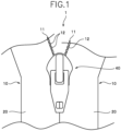
- FIG. 1 is a plan view schematically showing a water repellent treated slide fastener of the embodiment.
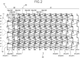
- FIG. 2 is a structure diagram showing a knitting structure of the knitted fastener stringer of the embodiment
- FIG. 3 is a structure diagram of each yarn that forms the knitted fastener stringer. Note that, in FIG. 2 and FIG. 3 , weft insertion yarns are drawn bent for not overlapping with points of the structure diagram to make them easier to see.
- a front and rear direction refers to a tape length direction of a fastener tape parallel to a sliding direction of a slider, in particular, a direction in which the slider slides to engage left and right element rows (a closing direction) refers to a front, a direction in which a slider slides to separate left and right element rows (a separating direction) refers to a rear.
- a left and right direction refers to a tape width direction of the fastener tape, for example, perpendicular to the sliding direction of a slider, and parallel to a top surface (an upper surface) and a back surface (a lower surface) of the fastener tape.
- An upper and lower direction refers to a direction perpendicular to the front and rear direction and the left and right direction, for example, a tape top and back direction perpendicular to the top surface and the back surface of the fastener tape.
- a direction of a side of the fastener tape on which a tab of the slider is disposed refers to an upper
- a direction of the opposite side refers to a lower.
- a direction parallel to the length direction of the fastener tape refers to a wale direction
- a direction perpendicular to the wale direction refers to a course direction
- a slide fastener 1 of the embodiment shown in FIG. 1 includes a pair of left and right knitted fastener stringers 10, and a slider 40 attached to left and right element rows 11 disposed on the knitted fastener stringers 10.
- a fastener chain is formed by the element rows 11 of the left and right fastener stringers 10 being engaged with each other over the whole length direction.
- a fastener tape 20 of the knitted fastener stringer 10 includes a tape top surface (a first tape surface), which is a surface of a side exposing outside, and a tape back surface (a second surface) disposed on the opposite side of the tape top surface.
- the element row 11 is disposed on the tape back surface side of the fastener tape 20.
- the slide fastener 1 of the embodiment is formed as so-called a back use type slide fastener of which the element rows 11 are not visible or are difficult to be visible being hidden in the back side of the fastener tape 20 in a closed state of the slide fastener 1.
- the slider 40 of the embodiment is formed substantially the same as sliders used for conventional back use type slide fasteners. For this reason, detailed explanations of the slider 40 are omitted in the embodiment.
- Each of the left and right fastener stringers 10 includes the fastener tape 20 that includes a tape body portion 21 and an element attaching portion 22, and a plurality of coiled continuous fastener elements 12 knitted in the element attaching portion 22.
- the element row 11 is formed along a length direction of the fastener tape 20 by a plurality of the fastener elements 12 knitted in the fastener tape 20.
- this fastener tape 20 On the tape top surface of this fastener tape 20, a film member made of synthetic resin (not shown in the drawings) is attached by adhesion. Furthermore, water repellent treatment is applied to the fastener tape 20 including the film member. Thus, the slide fastener 1 is provided with a water repellence property.
- the knitted fastener stringer of the present invention may be formed as a normal type knitted fastener stringer without a water repellence property by not applying water repellent treatment. The knitted fastener stringer of the present invention may also be formed without attaching the film member to the fastener tape 20.
- Each of the knitted slide fasteners 1 of the embodiment is knitted by a warp knitting machine (for example, a double raschel knitting machine) having two rows of needle beds comprising a back row B and a front row F.
- the back row B and the front row F of the needle beds are also respectively called a back needle row and a front needle row.
- each fastener element 12 of the embodiment is formed of one monofilament made of synthetic resin, and have substantially the same form as widely known fastener elements used in conventional knitted fastener stringers.
- each fastener element 12 of the embodiment includes a coupling head portion, an upper leg portion extending from an upper end portion of the coupling head portion in a tape width direction, a lower leg portion extending from a lower end portion of the coupling head portion in the tape width direction, and a connecting portion (also referred to a reversing portion) connecting the fastener elements 12 adjacent to each other in a tape length direction.
- the fastener element 12 is fixed by knitting the upper leg portion and the lower leg portion in the element attaching portion 22 with the coupling portion protruding outward from a tape side edge of the element attaching portion 22 side of the fastener tape 20 at the same time as the fastener tape 20 is knitted.
- a tape side edge of the element attaching portion 22 side of the fastener tape 20 is referred to a tape inner side edge
- a tape side edge of the opposite side is referred to a tape outer side edge.
- the tape inner side edge of the fastener tape 20 is a facing side edge that faces the fastener tape 20 of the knitted fastener stringer of 10 of a coupling counterpart.
- the fastener tape 20 of the embodiment has a warp knitting structure knitted by the warp knitting machine described above.
- This fastener tape 20 includes fourteen rows of wales, which are a first wale W1 to a fourteenth wale W14 from the tape inner side edge to the tape outer side edge.
- the wale disposed closest to the tape inner side edge of the fastener tape 20 refers to the first wale W1
- the second wale W2 to the fourteenth wale W14 are formed from the first wale W1 toward the tape outer side edge in a sequence in a course direction.
- the number of rows of wales formed on the fastener tape 20 is not limited, it can be increased or decreased according to such as usage of the knitted fastener stringer 10.
- the fastener tape 20 includes the tape body portion 21, and the element attaching portion 22 extending in a tape width direction from an inner side edge portion of the tape body portion 21 toward the side of the coupling counterpart.
- the element attaching portion 22 of the fastener tape 20 is formed by three rows of wales, the first wale W1 to the third wale W3.
- the tape body portion 21 is formed by eleven rows of wales, the fourth wale W4 to the fourteenth wale W14.
- an ear portion of the fastener tape 20 is formed by the three rows of wales, the twelfth wale W12 to the fourteenth wale W14, disposed close to the tape outer side edge of the tape body portion 21.
- a ground structure of the fastener tape 20 (that is, a ground structure of the tape body portion 21 and a ground structure of the element attaching portion 22) is knitted in a single structure by the back row B of the warp knitting machine.
- a fixing chain stitch yarn 34, which is described later, disposed on the element attaching portion 22 is knitted in a single structure by the front row F of the warp knitting machine to interlace with the ground structure of the element attaching portion 22.
- the ground structure of the fastener tape 20 is knitted using three kinds of yarns, a chain stitch yarn 31, a single satin stitch yarn 32, and a weft insertion yarn 33.
- the chain stitch yarns 31 are knitted in a knitting structure of (0-1/1-1/1-0/0-0), and disposed on each wale from the first wale W1 to the fourteenth wale W14.
- the chain stitch yarn 31 of each wale has open needle loops formed on each course, and sinker loops connecting needle loops adjacent to each other in a wale direction, a plurality of needle loops are connected to each other by sinker loops, and are formed in a chain shape along a wale direction on each wale.
- the thickest yarn of all the chain stitch yarns 31 disposed on the first wale W1 to the fourteenth wale W14 is disposed as a chain stitch yarn 31a disposed on the first Wale W1 of the tape inner side edge.
- the chain stitch yarn 31a disposed on the first wale W1 is 1.5 to 4 times thicker, preferably 3 times thicker, than the other chain stitch yarns 31b disposed on the element attaching portion 22 (in the case of the embodiment, the chain stitch yarns 31b disposed on the second wale W2 and the third wale W3).
- the chain stitch yarn 31a disposed on the first wale W1 has a thickness of 310 decitex
- the chain stitch yarns 31b disposed on the second wale W2 and the third wale W3 have a thickness of 110 decitex.
- the chain stitch yarns 31b disposed on the second wale W2 and the third wale W3, which practically fix the fastener element 12, do not need to be made thick, and a dimension in a tape width direction (a width dimension) from a boundary portion 23 between the element attaching portion 22 and the tape body portion 21 of the fastener tape 20 to the tape inner side edge of the element attaching portion 22 can be easily secured large.
- a distance of a gap formed between the left and right fastener tapes 20 can be small as 0.35 mm or less, preferably 0.30 mm or less.
- the chain stitch yarns 31c disposed on the twelfth wale W12 to the fourteenth wale W14 forming the ear portion of the tape body portion 21 are formed thicker than the chain stitch yarns 31d disposed on other than the ear portion of the tape body portion 21 (in the case of the embodiment, the chain stitch yarns 31d disposed on the fourth wale W4 to the eleventh wale W11).
- the chain stitch yarns 31d disposed on the fourth wale W4 to the eleventh wale W11 have a thickness of 110 decitex
- the chain stitch yarns 31c disposed on the twelfth wale W12 to the fourteenth wale W14 is formed by pulling together two yarns having a thickness of 110 decitex. That is, the chain stitch yarns 31c disposed on the twelfth wale W12 to the fourteenth wale W14 have a thickness of 220 decitex.
- a long and narrow belt-shape of the fastener tape 20 can be stably maintained by using such thick yarns for the chain stitch yarns 31c disposed on the ear portion.
- the single satin stitch yarns 32 are knitted in a knitting structure of (1-0/2-2/3-4/2-2). Each single satin stitch yarn 32 is disposed over four adjacent rows of wales. Additionally, the single satin stitch yarn 32 has closed needle loops alternately formed on two rows of wales, which are both the left and right ends of four rows of wales, and has sinker loops connect between needle loops of the wales of both ends.
- the needle loops of the single satin stitch yarn 32 are alternately formed in a wale direction on two wales disposed at a position three rows distant from each other in a course direction. That is, two wales on which the needle loops are not formed by the single satin stitch yarns 32 are disposed between the two wales on which the needle loops of the single satin stitch yarn 32 are formed.
- the sinker loops of the single satin stitch yarn 32 connect needle loops formed on one wale and needle loops formed on the other wale. For this reason, the sinker loops of the single satin stitch yarn 32 are disposed long over a distance of three stitches to across the two wales, in each interval between courses. In the embodiment, the sinker loops of each single satin stitch yarn 32 appear on the tape back surface (a tape surface of a side on which the film member is not attached) of the fastener tape 20.
- ten single satin stitch yarns 32 are disposed so that the needle loops of the single satin stitch yarns 32 are formed on each wale from the first wale W1 to the thirteenth wale W13.
- the needle loops form each wale from the first wale W1 to the thirteenth wale W13 include both needle loops of the needle loops of the chain stitch yarn 31 and the needle loops of the single satin stitch yarn 32.
- the fastener tape 20 is more likely to give an impression of being thin or an impression of being light because an outer edge portion of the fastener tape 20 can be formed thin. It is also easier to make the fastener tape 20 felt thin when touched with fingers. Furthermore, by reducing the number of the needle loops formed on the fourteenth wale W14 compared to the number of the needle loops formed on the other wales of the tape body portion 21, the flexibility of the fastener tape 20 can be improved.
- the single satin stitch yarns 32 of the embodiment include first single satin stitch yarns 32a alternately form needle loops on the wales of the element attaching portion 22 (the first wale W1, the second wale W2 or the third wale W3) and the wales of the tape body portion 21 (the fourth wale W4, the fifth wale W5 or the sixth wale W6), and second satin stitch yarns 32b form needle loops only on wales of the tape body portion 21.
- the sinker loops of the first single satin stitch yarns 32a are disposed across the boundary portion 23 of the tape body portion 21 and the element attaching portion 22.
- the boundary portion 23 of the tape body portion 21 and the element attaching portion 22 is placed between the third wale W3 and the fourth wale W4. That is, in the embodiment, the sinker loops of the three first single satin stitch yarns 32a and the two weft insertion yarns 33 are disposed across the boundary portion 23 of the tape body portion 21 and the element attaching portion 22 in each interval between courses. Furthermore, in this case, the sinker loops of the first single satin stitch yarn 32a and the two weft insertion yarns 33 are crossed in each interval between courses as described later.
- the tape strength of the boundary portion 23 of the tape body portion 21 and the element attaching portion 22, and the tape strength of a part close to the boundary portion 23 are enhanced.
- each of the first single satin stitch yarns 32a runs across the boundary portion 23 is formed thicker than the second single satin stitch yarn 32b.
- the first single satin stitch yarn 32a is 1.1 to 2.0 times thicker, preferably 1.4 to 1.6 times thicker than the second single satin stitch yarn 32b.
- the first single satin stitch yarn 32a of the embodiment has a thickness of 167 decitex
- the second single satin stitch yarn 32b has a thickness of 110 decitex.
- the tape strength of the boundary portion 23 of the tape body portion 21 and the element attaching portion 22 and the tape strength of a part close to the boundary portion 23 are more effectively enhanced.
- Such a part of which the tape strength is enhanced by the first single satin stitch yarns 32a is a part a flange portion of the slider 40 is easy to contact in the slide fastener 1. For this reason, even if the sliding operations of the slider 40 are repeated, the fastener tape 20 is less likely to be damaged thanks to the above-described high tape strength of the fastener tape including the first single satin stitch yarns 32a.
- a plurality of the weft insertion yarns 33 are inserted on the whole part of wales, the first wale W1 to the fourteenth wale W14.
- Each weft insertion yarn 33 is respectively inserted over three wales in a zigzag pattern.
- the weft insertion yarns 33 of the embodiment are inserted in a direction crossing the sinker loops of the single satin stitch yarns 32 in each interval between courses.
- the fact the weft insertion yarns 33 and the sinker loops of the single satin stitch yarn 32 are crossed each interval between courses means a direction in which the weft insertion yarns 33 are folded back at the needle loops and a direction in which the sinker loops of the single satin stitch yarns 32 extend from the needle loops are shifted by one course in a wale direction.
- the fastener tape 20 can be reinforced by such weft insertion yarns 33 inserted in the fastener tape 20 while the flexibility and the texture of the fastener tape 20 are maintained properly.
- the weft insertion yarn 33a folded back on the first wale W1 and disposed closest to the tape inner side edge is formed thinner than the other weft insertion yarns 33 disposed on the fastener tape 20.
- a distance of the gap formed between the left and right fastener tapes 20 can be smaller.
- the fixing chain stitch yarns 34 are knitted in the second wale W2 and the third wale W3 of the element attaching portion 22 in a knitting structure of (0-0/0-1/1-1/1-0) by the front row F of the warp knitting machine as described above. That is, the ground structure of the fastener tape 20 and a knitting part of the fixing chain stitch yarns 34 are knitted in different single structures from each other respectively by the back row B and the front row F of the warp knitting machine. For this reason, the flexibility of the fastener tape 20 can be improved, and the weight reduction and the productivity of the knitted fastener stringer 10 can be enhanced.
- the upper leg portions and the lower leg portions of the fastener elements 12 are inserted so that they are sandwiched between the ground structure of the element attaching portion 22 and the fixing chain stitch yarns 34. Additionally, the sinker loops of the fixing chain stitch yarns 34 are crossed and interlaced with the ground structure of the element attaching portion 22. More specifically, the sinker loops of the fixing chain stitch yarns 34 are interlaced and knitted with the sinker loops at least one of the chain stitch yarns 31 and the single satin stitch yarns 32 forming the ground structure. Thus, the fixing chain stitch yarns 34 are integrated into the ground structure of the element attaching portion 22. Furthermore, the fastener elements 12 are knitted with the fixing chain stitch yarns 34 and firmly fixed in the element attaching portion 22. In this case, the fastener elements 12 are fixed by holding the upper leg portions and the lower leg portions of the fastener element 12 between the fixing chain stitch yarns 34 and the ground structure of the element attaching portion 22.
- the fixing chain stitch yarns 34 include a first fixing chain stitch yarn 34a close to the tape inner side edge disposed on the second wale W2, and a second fixing chain stitch yarn 34b close to the tape body portion 21 disposed on the third wale W3.
- the thickest yarns of all the yarns forming the ground structure of the fastener tape 20 are used for the first fixing chain stitch yarn 34a and the second fixing chain stitch yarn 34b.
- the first fixing chain stitch yarn 34a and the second fixing chain stitch yarn 34b are formed by pulling together two yarns having a thickness of 220 decitex.
- the fastener elements 12 can be firmly fixed in the element attaching portion 22 so that the positions of the fastener elements 12 are not shifted.
- the second fixing chain stitch yarn 34b of the embodiment is formed including two yarns having a thickness of 220 decitex and auxiliary fibers to be removed in knitting process of warp knitting of the knitted fastener stringer 10 as described later. These auxiliary fibers are pulled out from the fastener tape 20 and no longer exist after the knitting process. For this reason, in the manufactured knitted fastener stringer 10, the second fixing chain stitch yarn 34b is formed by the two yarns having a thickness of 220 decitex. Note that, in relation to the first fixing chain stitch yarn 34a of the embodiment, knitting process of the knitted fastener stringer 10 is performed without auxiliary fibers.
- the strength to hold down the fastener elements 12 by the second fixing chain stitch yarn 34bs can be weaker than the strength to hold down the fastener elements 12 by the first fixing chain stitch yarns 34a.
- the motion of each fastener element 12 knitted in the fastener tape 20 is easier to be allowed compared to the case in which knitting process is performed without including fibers to be removed in the first fixing chain stitch yarns 34a and second fixing chain stitch yarns 34b.
- the flexibility of the knitted fastener stringer 10 can be more effectively enhanced, and the slidability of the slider 40 of the slide fastener 1 can be more improved.
- the knitted fastener stringer 10 is knitted without including the auxiliary fibers in the first fixing yarns 34a, the fastener elements 12 can be stably fixed in the element attaching portion 22.
- the coupling strength (the strength against pulling in width direction) of the fastener chain and the coupling strength (the strength against bending) in bending the fastener chain in the tape top and back direction can be properly secured.
- knitting process of warp knitting for knitting the knitted fastener stringer 10 is performed using a warp knitting machine having two rows of needle beds comprising a back row B and a front row F.
- the needle loops of the fixing chain stitch yarns 34 are formed and the sinker loops of the fixing chain stitch yarns 34 are interlaced with the ground structure of the fastener tape 20 by the front row F.
- the fastener elements 12 molded by monofilament are inserted between the ground structure of the fastener tape 20 and the fixing chain stitch yarns 34.
- the ground structure of the fastener tape 20 is knitted using the chain stitch yarns 31, the single satin stitch yarns 32, and the weft insertion yarns 33 described above. Additionally, the fastener elements 12 are knitted in the fastener tape 20 using the first fixing chain stitch yarn 34a formed by pulling together the two yarns having a thickness of 220 decitex, and the second fixing chain stitch yarn 34b includes the pulled together two yarns having a thickness of 220 decitex and auxiliary fibers, as the fixing chain stitch yarns 34.
- the knitted fastener stringer 10 thus obtained includes such a warp knitting structure as shown in FIG. 2 and FIG. 3 . Note that, in this knitting process, one knitted fastener stringer 10 may be continuously manufactured, or a fastener chain may be continuously manufactured by knitting the two knitted fastener stringers 10 in a state that the left and right element rows 11 are coupled with each other.
- a pair of the obtained knitted fastener stringers 10 are combined and formed into a fastener chain, the auxiliary fibers included in the second fixing chain stitch yarn 34b are removed. And then, adhesive is applied to the tape top surface of the left and right fastener tapes 20 of the fastener chain. Subsequently, one film member made of synthetic resin is overlapped and attached to the tape top surface on which the adhesive is applied. Thus, the film member is bonded to the fastener tape 20.
- type and material of the adhesive to bond the film member is not limited.
- a method and means to bond the film member to the fastener tape 20 are also not limited, and the film member may be attached to the fastener tape 20 by a method or means other than bonding.
- water repellent treatment is applied to the fastener chain on which the film member is attached. Then, by cutting the film member at a boundary portion of the left and right fastener tapes 20 along a length direction of the fastener chain, the fastener chain with a water repellence property is manufactured.
- the slide fastener 1 with a water repellence property shown in the FIG. 1 is manufactured.
- the ground structures of the left and right fastener tapes 20 are knitted using the single satin stitch yarns 32 that forms sinker loops in each interval long between courses. For this reason, the left and right knitted fastener stringers 10 have a high flexibility.
- the sinker loops of the single satin stitch yarns 32 appear long in a direction inclined to a tape width direction of the fastener tape 20 on the tape back surface in which the fastener elements 12 are knitted (in other words, the tape surface on which the film member is not attached). For this reason, the tape back surface of the fastener tape 20 is formed into a smooth surface that can obtain a pleasant hand feeling.
- the fastener tape 20 can also have a good texture by the single satin yarns 32.
- the tape strength of the boundary portion 23 between the tape body portion 21 and the element attaching portion 22 of the fastener tape 20, and a part close to the boundary portion 23 are enhanced by the three thick first single satin stitch yarns 32a and the two weft insertion yarns 33 as described above.
- the fastener tape 20 can be suppressed from damage caused by such as friction against the slider 40.
- Such a slide fastener 1 of the embodiment that is soft, good in texture, and has a proper tape strength is preferred for such clothing that has a direct contact with the skin, clothing that is formed of thin cloth, and the like.
- a distance of the gap formed between the left and right fastener tapes in a closed state of the slide fastener 1 can be made to be 0.35 mm or less, preferably 0.30 mm or less.
- the coupled left and right element rows 11 can be made difficult to be visible from the tape top surface side of the fastener tape 20 through the gap between the left and right fastener tapes 20.
- a length of the film member bonded to the fastener tape 20 extending from the inner side edge of the fastener tape 20 to the coupling head portion side in a tape width direction can be made short because a distance of the gap between the left and right fastener tapes 20 becomes smaller.
- an appearance defect such as a white line seen between the left and right fastener tapes in conventional water repellent treated slide fasteners, for example, can be made difficult to occur.
- an appearance quality of the water repellent treated slide fastener 1 can be improved.
- the slide fastener 1 can have a good and stable water repellence property because a distance of the gap between the left and right fastener tapes 20 becomes smaller.
- knitted fastener stringer 10 of the embodiment described above is used for a back use type slide fastener 1
- knitted fastener stringer of the present invention can also be applied to a normal type slide fastener of which element rows expose outside.
- the auxiliary fibers are included beforehand only in the second fixing chain stitch yarn 34b of the fixing chain stitch yarns 34, then the auxiliary fibers are removed after the knitting process.
- the auxiliary fibers may be included only in the first fixing chain stitch yarn 34a of the fixing chain stitch yarns 34, or the auxiliary fibers may be included in both the first fixing chain stitch yarn 34a and the second fixing chain stitch yarn 34b of the fixing chain stitch yarns 34 in the knitting process of the knitted fastener stringer 10.
- knitting process of the knitted fastener stringer 10 may be performed without including auxiliary fibers.
- water-soluble fibers are used as auxiliary fibers, for example, and to remove the fibers after the knitting process includes to dissolve the water-soluble fibers by liquid.
Landscapes
- Engineering & Computer Science (AREA)
- Textile Engineering (AREA)
- Slide Fasteners (AREA)
Claims (7)
- Maschenverschlussstreifen (10), der Folgendes aufweistein Verschlußband (20), das eine Kettenmaschenstruktur und eine Vielzahl von Verschlußelementen (12) aufweist, die aus einem aus Kunstharz hergestellten Monofilament gebildet sind, wobei das Verschlußband (20) einen Bandkörperabschnitt (21) aufweist, und einen Elementbefestigungsabschnitt (22) aufweist, der sich von einem Seitenkantenabschnitt des Bandkörperabschnitts (21) in einer Bandbreitenrichtung erstreckt und in dem ein Teil des Verschlusselements (12) eingearbeitet ist, wobei das Verschlussband (20) eine Vielzahl von Kettenstichgarnen (31) aufweist, die eine Vielzahl von Nadelschlingen in einer Kettenform entlang einer Maschenstäbchen-Richtung ausbilden,wobei das Verschlussband (20) eine Grundstruktur aufweist, die in einer einzigen Struktur durch das Kettenstäbchengarn (31) gearbeitet ist, und ein Schusseintragsgarn (33), das über eine Vielzahl von Maschenstäbchen in einem Zickzackmuster eingearbeitet ist,wobei das Verschlusselement (12) zwischen der Grundstruktur des Verschlussbandes (20) und einem Fixierkettenstichgarn (34), das in einer einzigen Struktur gearbeitet ist, eingefügt und verarbeitet wird,und wobei das an dem innersten Maschenstäbchen (W1) des Elementbefestigungsabschnitts (22), der am weitesten von dem Bandkörperabschnitt (21) entfernt ist, angeordnete Kettenstichgarn (31) das dickste aller in der Grundstruktur des Verschlussbandes (20) verwendeten Kettenstichgarne (31) ist,dadurch gekennzeichnet, dass ein einfaches Plattstichgarn (32) abwechselnd Nadelschlingen auf zwei Maschenstäbchen ausbildet, die in einer Position angeordnet sind, die drei Maschenstäbchen voneinander entfernt ist, unddie Nadelschlingen, die das äußerste Maschenstäbchen (W14) des Bandkörpers (21) ausbilden, das an der vom Elementbefestigungsabschnitt (22) am weitesten entfernten Stelle angeordnet ist, nur Nadelschlingen des Kettenstichgarns (31) aufweisen, unddie Nadelschlingen, die Maschenstäbchen (W1~W13) mit Ausnahme des äußersten Maschenstäbchens (W14) des Bandkörperteils (21) ausbilden, die Nadelschlingen des Kettenstichgarns (31) und die Nadelschlingen des einfachen Plattstichgarns (32) aufweisen.
- Maschenverschlussstreifen nach Anspruch 1, dadurch gekennzeichnet, daß
wenigstens drei der einzelnen Plattstichgarne (32) und die wenigstens zwei der Schußeintragsgarne (33) in Richtungen angeordnet sind, die sich in einem Intervall zwischen Maschenstäbchen (W3, W4) an einem Grenzabschnitt (23) des Bandkörperabschnitts (21) und dem Elementbefestigungsabschnitt (22) kreuzen. - Maschenverschlussstreifen nach Anspruch 1 oder 2, dadurch gekennzeichnet, daß
die einzelnen Plattstichgarne (32) ein erstes einzelnes Plattstichgarn (32a) aufweisen, das abwechselnd Nadelschlingen auf einem Maschenstäbchen (W1, W2, W3) des Elementbefestigungsabschnitts (22) und auf einem Maschenstäbchen (W4, W5, W6) des Bandkörperabschnitts (21) ausbildet, und ein zweites einfaches Plattstichgarn (32b), das abwechselnd Nadelschlingen auf zwei Maschenstäbchen (W4~W13) des Bandkörperabschnitts (21) ausbildet, und ferner dadurch gekennzeichnet, dass das erste einfache Plattstichgarn (32a) dicker ist als das zweite einfache Plattstichgarn (32b). - Verschlußkette, dadurch gekennzeichnet, daß sie zwei Maschenverschlussstreifen (10) nach einem der Ansprüche 1-3 aufweist, die an den Verschlußelementreihen (11) an einer Bandrückseite jedes Verschlußbandes (20) aneinander angebracht sind.
- Verschlußkette nach Anspruch 4, dadurch gekennzeichnet, daß
ein Abstand, der eine Lücke zwischen den beiden Verschlussbändern (20) ausbildet, 0,35 mm oder weniger in der Verschlusskette beträgt, die durch Ineinandergreifen von Elementreihen (11) der beiden Verschlussstreifen (10) gebildet wird. - Verschlußkette nach Anspruch 4 oder 5, dadurch gekennzeichnet, daßdas Verschlußband (20) eine erste Bandfläche auf der Seite aufweist, in die die Verschlußelemente (12) gearbeitet sind, und eine zweite Bandfläche auf der der ersten Bandfläche gegenüberliegenden Seite, und daßein aus Kunstharz hergestelltes Folienelement an der zweiten Bandfläche des Verschlussbandes (20) angebracht ist.
- Herstellungsverfahren für einen Maschenverschlussstreifen, das Folgendes aufweist ein Befestigungsband (20) mit einer Kettenmaschenstruktur und einer Vielzahl von Befestigungselementen (12), die aus einem aus Kunstharz hergestellten Monofilament ausgebildet sind, wobei das Befestigungsband (20) einen Bandkörperabschnitt (21) aufweist, und einen Elementbefestigungsabschnitt (22) aufweist, der sich von einem Seitenkantenabschnitt des Bandkörperabschnitts (21) in einer Bandbreitenrichtung erstreckt und in dem ein Teil des Verschlusselements (12) gearbeitet ist, wobei das Verschlussband (20) eine Vielzahl von Kettenstichgarnen (31) aufweist, die eine Vielzahl von Nadelschlingen in einer Kettenform entlang einer Maschenstäbchen-Richtung ausbilden,
wobei das Verfahren Folgendes aufweist:Einfügen und Verarbeiten der Verschlusselemente (12) zwischen einer Grundstruktur des Verschlussbandes (20) und einem stabilen Maschenstäbchengarn (34), das in einer einzigen Struktur gearbeitet ist, während die Grundstruktur des Verschlussbandes (20) in einer einzigen Struktur unter Verwendung des Maschenstäbchengarns (31) erzeugt wird, und ein Schusseintragsgarn (33) über eine Vielzahl von Maschenstäbchen in einem Zickzackmuster eingefügt wird,Verwendung eines dicksten Garns aller Kettenstichgarne (31), die in der Grundstruktur des Verschlussbandes (20) verwendet werden, für das Kettenstichgarn (31), das auf dem innersten Maschenstäbchen (W1) des Elementbefestigungsabschnitts (22) angeordnet ist, der am weitesten von dem Bandkörperabschnitt (21) entfernt ist, undgekennzeichnet durch ein einzelnes Plattstichgarn (32), das abwechselnd Nadelschlingen auf zwei Maschenstäbchen ausbildet, die an einer Position angeordnet sind, die drei Reihen voneinander entfernt ist, undErzeugen des Verschlussbandes (20), bei dem die Nadelschlingen, die das äußerste Maschenstäbchen (W14) am Bandkörperabschnitt (21) ausbilden, der an der am weitesten vom Elementbefestigungsabschnitt (22) entfernten Position angeordnet ist, nur Nadelschlingen des Kettenstichgarns (31) aufweisen, und die Nadelschlingen, die Maschenstäbchen (W1~W13) mit Ausnahme des äußersten Maschenstäbchen (W14) am Bandkörperabschnitt (21) ausbilden, die Nadelschlingen des Kettenstichgarns (31) und die Nadelschlingen des einfachen Plattstichgarns (32) einschließen.
Applications Claiming Priority (1)
| Application Number | Priority Date | Filing Date | Title |
|---|---|---|---|
| PCT/JP2019/040625 WO2021074992A1 (ja) | 2019-10-16 | 2019-10-16 | 編込みファスナーストリンガー、ファスナーチェーン、及び編込みファスナーストリンガーの製造方法 |
Publications (3)
| Publication Number | Publication Date |
|---|---|
| EP4046524A1 EP4046524A1 (de) | 2022-08-24 |
| EP4046524A4 EP4046524A4 (de) | 2022-10-12 |
| EP4046524B1 true EP4046524B1 (de) | 2024-10-30 |
Family
ID=75537518
Family Applications (1)
| Application Number | Title | Priority Date | Filing Date |
|---|---|---|---|
| EP19948957.6A Active EP4046524B1 (de) | 2019-10-16 | 2019-10-16 | Gewirkte verschlussleiste, reissverschluss und verfahren zum herstellen der gewirkten verschlussleiste |
Country Status (6)
| Country | Link |
|---|---|
| US (1) | US12016435B2 (de) |
| EP (1) | EP4046524B1 (de) |
| JP (1) | JP7191499B2 (de) |
| CN (1) | CN114554902B (de) |
| TW (1) | TWI742620B (de) |
| WO (1) | WO2021074992A1 (de) |
Family Cites Families (21)
| Publication number | Priority date | Publication date | Assignee | Title |
|---|---|---|---|---|
| JPS546940B2 (de) * | 1971-08-18 | 1979-04-02 | ||
| JPS5952909U (ja) * | 1982-09-29 | 1984-04-07 | ワイケイケイ株式会社 | スライドフアスナ− |
| JP3396335B2 (ja) | 1995-05-12 | 2003-04-14 | ワイケイケイ株式会社 | 編込みスライドファスナー |
| JP3526390B2 (ja) * | 1997-05-02 | 2004-05-10 | Ykk株式会社 | 反射性スライドファスナー用経編テープ |
| JP3580725B2 (ja) | 1999-04-30 | 2004-10-27 | Ykk株式会社 | 防水性を有するスライドファスナーの製造方法 |
| JP2002360315A (ja) * | 2001-06-07 | 2002-12-17 | Ykk Corp | 編込みスライドファスナー |
| JP3966826B2 (ja) * | 2003-02-28 | 2007-08-29 | Ykk株式会社 | 吸水性ファスナー |
| US7293434B2 (en) * | 2003-06-02 | 2007-11-13 | Ykk Corporation | Knitted/woven concealed type slide fastener |
| JP4046699B2 (ja) | 2004-02-17 | 2008-02-13 | Ykk株式会社 | 編込みスライドファスナー |
| JP4450758B2 (ja) * | 2005-03-25 | 2010-04-14 | Ykk株式会社 | 編込みスライドファスナー |
| JP4731378B2 (ja) | 2006-03-31 | 2011-07-20 | Ykk株式会社 | ファスナーテープ及びファスナーストリンガー |
| US7739887B2 (en) * | 2007-06-08 | 2010-06-22 | Da-An Hung | Knitted band for zipper |
| WO2009128140A1 (ja) * | 2008-04-15 | 2009-10-22 | Ykk株式会社 | 編込みスライドファスナー用ファスナーストリンガー |
| WO2011007411A1 (ja) * | 2009-07-13 | 2011-01-20 | Ykk株式会社 | 編込みファスナーストリンガー |
| KR101388289B1 (ko) | 2009-12-25 | 2014-04-22 | 와이케이케이 가부시끼가이샤 | 편입 슬라이드 파스너 |
| ES2735439T3 (es) | 2010-03-29 | 2019-12-18 | Ykk Corp | Cinta de cierre y banda de cierre |
| US20130174767A1 (en) | 2010-09-29 | 2013-07-11 | Ykk Corporation | Fastener Stringer Provided with Knit Tape |
| JP5459273B2 (ja) * | 2011-06-30 | 2014-04-02 | 株式会社デンソー | 雨滴検出装置 |
| JPWO2013011559A1 (ja) * | 2011-07-19 | 2015-02-23 | Ykk株式会社 | 編込みファスナーストリンガー |
| CN103687510B (zh) | 2011-07-19 | 2016-01-20 | Ykk株式会社 | 编入拉链条 |
| EP2769638B1 (de) * | 2011-10-19 | 2017-06-28 | YKK Corporation | Reissverschluss und verdeckter reissverschluss |
-
2019
- 2019-10-16 EP EP19948957.6A patent/EP4046524B1/de active Active
- 2019-10-16 WO PCT/JP2019/040625 patent/WO2021074992A1/ja not_active Ceased
- 2019-10-16 JP JP2021552031A patent/JP7191499B2/ja active Active
- 2019-10-16 CN CN201980100651.9A patent/CN114554902B/zh active Active
- 2019-10-16 US US17/765,078 patent/US12016435B2/en active Active
-
2020
- 2020-04-20 TW TW109113132A patent/TWI742620B/zh active
Also Published As
| Publication number | Publication date |
|---|---|
| TW202116209A (zh) | 2021-05-01 |
| TWI742620B (zh) | 2021-10-11 |
| US20220386747A1 (en) | 2022-12-08 |
| US12016435B2 (en) | 2024-06-25 |
| EP4046524A4 (de) | 2022-10-12 |
| CN114554902A (zh) | 2022-05-27 |
| EP4046524A1 (de) | 2022-08-24 |
| CN114554902B (zh) | 2024-03-15 |
| JPWO2021074992A1 (de) | 2021-04-22 |
| WO2021074992A1 (ja) | 2021-04-22 |
| JP7191499B2 (ja) | 2022-12-19 |
Similar Documents
| Publication | Publication Date | Title |
|---|---|---|
| TWI590776B (zh) | Zipper-attached items and Zipper-attached items | |
| TW201108961A (en) | A zipper strip for concealed zipper | |
| CN100551291C (zh) | 针织、机织的隐形拉链 | |
| TW201236595A (en) | Slide fastener and method for manufacturing same | |
| JP3552947B2 (ja) | 編込みスライドファスナー | |
| JP3708046B2 (ja) | スライドファスナー | |
| KR100529697B1 (ko) | 슬라이드 파스너용 경편테이프 | |
| TWI403284B (zh) | Woven into the chain | |
| CN109475207B (zh) | 编织拉链链牙带 | |
| CN103687510B (zh) | 编入拉链条 | |
| TWI411409B (zh) | Zipper chain and zipper chain | |
| JP4731378B2 (ja) | ファスナーテープ及びファスナーストリンガー | |
| EP4046524B1 (de) | Gewirkte verschlussleiste, reissverschluss und verfahren zum herstellen der gewirkten verschlussleiste | |
| TWI410225B (zh) | A zipper chain, and a method of manufacturing a fastener tape | |
| JP7496003B2 (ja) | ファスナーストリンガー及びファスナーストリンガーの製造方法 | |
| CN107296337A (zh) | 链带和拉链 | |
| EP2177126B1 (de) | Leiste mit in Querrichtung dehnbarem, kettengewirkten Band für einen Reißverschluss | |
| KR100761572B1 (ko) | 편직입 숨김 슬라이드 고정구 | |
| HK1174229B (en) | Fastener | |
| HK1106403B (en) | Fastener tape and fastener stringer |
Legal Events
| Date | Code | Title | Description |
|---|---|---|---|
| STAA | Information on the status of an ep patent application or granted ep patent |
Free format text: STATUS: THE INTERNATIONAL PUBLICATION HAS BEEN MADE |
|
| PUAI | Public reference made under article 153(3) epc to a published international application that has entered the european phase |
Free format text: ORIGINAL CODE: 0009012 |
|
| STAA | Information on the status of an ep patent application or granted ep patent |
Free format text: STATUS: REQUEST FOR EXAMINATION WAS MADE |
|
| 17P | Request for examination filed |
Effective date: 20220331 |
|
| AK | Designated contracting states |
Kind code of ref document: A1 Designated state(s): AL AT BE BG CH CY CZ DE DK EE ES FI FR GB GR HR HU IE IS IT LI LT LU LV MC MK MT NL NO PL PT RO RS SE SI SK SM TR |
|
| A4 | Supplementary search report drawn up and despatched |
Effective date: 20220909 |
|
| RIC1 | Information provided on ipc code assigned before grant |
Ipc: A44B 19/56 20060101ALN20220905BHEP Ipc: D04B 21/16 20060101ALI20220905BHEP Ipc: A44B 19/34 20060101AFI20220905BHEP |
|
| DAV | Request for validation of the european patent (deleted) | ||
| DAX | Request for extension of the european patent (deleted) | ||
| RIC1 | Information provided on ipc code assigned before grant |
Ipc: A44B 19/56 20060101ALN20240430BHEP Ipc: D04B 21/16 20060101ALI20240430BHEP Ipc: A44B 19/34 20060101AFI20240430BHEP |
|
| GRAP | Despatch of communication of intention to grant a patent |
Free format text: ORIGINAL CODE: EPIDOSNIGR1 |
|
| STAA | Information on the status of an ep patent application or granted ep patent |
Free format text: STATUS: GRANT OF PATENT IS INTENDED |
|
| RIC1 | Information provided on ipc code assigned before grant |
Ipc: A44B 19/56 20060101ALN20240624BHEP Ipc: D04B 21/16 20060101ALI20240624BHEP Ipc: A44B 19/34 20060101AFI20240624BHEP |
|
| RIC1 | Information provided on ipc code assigned before grant |
Ipc: A44B 19/56 20060101ALN20240628BHEP Ipc: D04B 21/16 20060101ALI20240628BHEP Ipc: A44B 19/34 20060101AFI20240628BHEP |
|
| RIC1 | Information provided on ipc code assigned before grant |
Ipc: A44B 19/56 20060101ALN20240709BHEP Ipc: D04B 21/16 20060101ALI20240709BHEP Ipc: A44B 19/34 20060101AFI20240709BHEP |
|
| INTG | Intention to grant announced |
Effective date: 20240730 |
|
| GRAS | Grant fee paid |
Free format text: ORIGINAL CODE: EPIDOSNIGR3 |
|
| GRAA | (expected) grant |
Free format text: ORIGINAL CODE: 0009210 |
|
| STAA | Information on the status of an ep patent application or granted ep patent |
Free format text: STATUS: THE PATENT HAS BEEN GRANTED |
|
| P01 | Opt-out of the competence of the unified patent court (upc) registered |
Free format text: CASE NUMBER: APP_52246/2024 Effective date: 20240917 |
|
| AK | Designated contracting states |
Kind code of ref document: B1 Designated state(s): AL AT BE BG CH CY CZ DE DK EE ES FI FR GB GR HR HU IE IS IT LI LT LU LV MC MK MT NL NO PL PT RO RS SE SI SK SM TR |
|
| REG | Reference to a national code |
Ref country code: GB Ref legal event code: FG4D |
|
| REG | Reference to a national code |
Ref country code: CH Ref legal event code: EP |
|
| REG | Reference to a national code |
Ref country code: DE Ref legal event code: R096 Ref document number: 602019061353 Country of ref document: DE |
|
| REG | Reference to a national code |
Ref country code: IE Ref legal event code: FG4D |
|
| REG | Reference to a national code |
Ref country code: LT Ref legal event code: MG9D |
|
| REG | Reference to a national code |
Ref country code: NL Ref legal event code: MP Effective date: 20241030 |
|
| PG25 | Lapsed in a contracting state [announced via postgrant information from national office to epo] |
Ref country code: IS Free format text: LAPSE BECAUSE OF FAILURE TO SUBMIT A TRANSLATION OF THE DESCRIPTION OR TO PAY THE FEE WITHIN THE PRESCRIBED TIME-LIMIT Effective date: 20250228 Ref country code: PT Free format text: LAPSE BECAUSE OF FAILURE TO SUBMIT A TRANSLATION OF THE DESCRIPTION OR TO PAY THE FEE WITHIN THE PRESCRIBED TIME-LIMIT Effective date: 20250228 Ref country code: HR Free format text: LAPSE BECAUSE OF FAILURE TO SUBMIT A TRANSLATION OF THE DESCRIPTION OR TO PAY THE FEE WITHIN THE PRESCRIBED TIME-LIMIT Effective date: 20241030 |
|
| PG25 | Lapsed in a contracting state [announced via postgrant information from national office to epo] |
Ref country code: NL Free format text: LAPSE BECAUSE OF FAILURE TO SUBMIT A TRANSLATION OF THE DESCRIPTION OR TO PAY THE FEE WITHIN THE PRESCRIBED TIME-LIMIT Effective date: 20241030 Ref country code: FI Free format text: LAPSE BECAUSE OF FAILURE TO SUBMIT A TRANSLATION OF THE DESCRIPTION OR TO PAY THE FEE WITHIN THE PRESCRIBED TIME-LIMIT Effective date: 20241030 |
|
| REG | Reference to a national code |
Ref country code: AT Ref legal event code: MK05 Ref document number: 1736030 Country of ref document: AT Kind code of ref document: T Effective date: 20241030 |
|
| PG25 | Lapsed in a contracting state [announced via postgrant information from national office to epo] |
Ref country code: BG Free format text: LAPSE BECAUSE OF FAILURE TO SUBMIT A TRANSLATION OF THE DESCRIPTION OR TO PAY THE FEE WITHIN THE PRESCRIBED TIME-LIMIT Effective date: 20241030 |
|
| PG25 | Lapsed in a contracting state [announced via postgrant information from national office to epo] |
Ref country code: ES Free format text: LAPSE BECAUSE OF FAILURE TO SUBMIT A TRANSLATION OF THE DESCRIPTION OR TO PAY THE FEE WITHIN THE PRESCRIBED TIME-LIMIT Effective date: 20241030 |
|
| PG25 | Lapsed in a contracting state [announced via postgrant information from national office to epo] |
Ref country code: NO Free format text: LAPSE BECAUSE OF FAILURE TO SUBMIT A TRANSLATION OF THE DESCRIPTION OR TO PAY THE FEE WITHIN THE PRESCRIBED TIME-LIMIT Effective date: 20250130 |
|
| PG25 | Lapsed in a contracting state [announced via postgrant information from national office to epo] |
Ref country code: AT Free format text: LAPSE BECAUSE OF FAILURE TO SUBMIT A TRANSLATION OF THE DESCRIPTION OR TO PAY THE FEE WITHIN THE PRESCRIBED TIME-LIMIT Effective date: 20241030 Ref country code: LV Free format text: LAPSE BECAUSE OF FAILURE TO SUBMIT A TRANSLATION OF THE DESCRIPTION OR TO PAY THE FEE WITHIN THE PRESCRIBED TIME-LIMIT Effective date: 20241030 Ref country code: GR Free format text: LAPSE BECAUSE OF FAILURE TO SUBMIT A TRANSLATION OF THE DESCRIPTION OR TO PAY THE FEE WITHIN THE PRESCRIBED TIME-LIMIT Effective date: 20250131 |
|
| PG25 | Lapsed in a contracting state [announced via postgrant information from national office to epo] |
Ref country code: PL Free format text: LAPSE BECAUSE OF FAILURE TO SUBMIT A TRANSLATION OF THE DESCRIPTION OR TO PAY THE FEE WITHIN THE PRESCRIBED TIME-LIMIT Effective date: 20241030 |
|
| PG25 | Lapsed in a contracting state [announced via postgrant information from national office to epo] |
Ref country code: RS Free format text: LAPSE BECAUSE OF FAILURE TO SUBMIT A TRANSLATION OF THE DESCRIPTION OR TO PAY THE FEE WITHIN THE PRESCRIBED TIME-LIMIT Effective date: 20250130 |
|
| PG25 | Lapsed in a contracting state [announced via postgrant information from national office to epo] |
Ref country code: SM Free format text: LAPSE BECAUSE OF FAILURE TO SUBMIT A TRANSLATION OF THE DESCRIPTION OR TO PAY THE FEE WITHIN THE PRESCRIBED TIME-LIMIT Effective date: 20241030 |
|
| PG25 | Lapsed in a contracting state [announced via postgrant information from national office to epo] |
Ref country code: DK Free format text: LAPSE BECAUSE OF FAILURE TO SUBMIT A TRANSLATION OF THE DESCRIPTION OR TO PAY THE FEE WITHIN THE PRESCRIBED TIME-LIMIT Effective date: 20241030 |
|
| PG25 | Lapsed in a contracting state [announced via postgrant information from national office to epo] |
Ref country code: EE Free format text: LAPSE BECAUSE OF FAILURE TO SUBMIT A TRANSLATION OF THE DESCRIPTION OR TO PAY THE FEE WITHIN THE PRESCRIBED TIME-LIMIT Effective date: 20241030 |
|
| PG25 | Lapsed in a contracting state [announced via postgrant information from national office to epo] |
Ref country code: RO Free format text: LAPSE BECAUSE OF FAILURE TO SUBMIT A TRANSLATION OF THE DESCRIPTION OR TO PAY THE FEE WITHIN THE PRESCRIBED TIME-LIMIT Effective date: 20241030 |
|
| PG25 | Lapsed in a contracting state [announced via postgrant information from national office to epo] |
Ref country code: SK Free format text: LAPSE BECAUSE OF FAILURE TO SUBMIT A TRANSLATION OF THE DESCRIPTION OR TO PAY THE FEE WITHIN THE PRESCRIBED TIME-LIMIT Effective date: 20241030 |
|
| PG25 | Lapsed in a contracting state [announced via postgrant information from national office to epo] |
Ref country code: CZ Free format text: LAPSE BECAUSE OF FAILURE TO SUBMIT A TRANSLATION OF THE DESCRIPTION OR TO PAY THE FEE WITHIN THE PRESCRIBED TIME-LIMIT Effective date: 20241030 |
|
| PG25 | Lapsed in a contracting state [announced via postgrant information from national office to epo] |
Ref country code: IT Free format text: LAPSE BECAUSE OF FAILURE TO SUBMIT A TRANSLATION OF THE DESCRIPTION OR TO PAY THE FEE WITHIN THE PRESCRIBED TIME-LIMIT Effective date: 20241030 |
|
| REG | Reference to a national code |
Ref country code: DE Ref legal event code: R097 Ref document number: 602019061353 Country of ref document: DE |
|
| PLBE | No opposition filed within time limit |
Free format text: ORIGINAL CODE: 0009261 |
|
| STAA | Information on the status of an ep patent application or granted ep patent |
Free format text: STATUS: NO OPPOSITION FILED WITHIN TIME LIMIT |
|
| PG25 | Lapsed in a contracting state [announced via postgrant information from national office to epo] |
Ref country code: SE Free format text: LAPSE BECAUSE OF FAILURE TO SUBMIT A TRANSLATION OF THE DESCRIPTION OR TO PAY THE FEE WITHIN THE PRESCRIBED TIME-LIMIT Effective date: 20241030 |
|
| 26N | No opposition filed |
Effective date: 20250731 |
|
| PGFP | Annual fee paid to national office [announced via postgrant information from national office to epo] |
Ref country code: DE Payment date: 20250902 Year of fee payment: 7 |