EP4045338B1 - Reifen für ein landwirtschaftliches fahrzeug - Google Patents
Reifen für ein landwirtschaftliches fahrzeug Download PDFInfo
- Publication number
- EP4045338B1 EP4045338B1 EP20801332.6A EP20801332A EP4045338B1 EP 4045338 B1 EP4045338 B1 EP 4045338B1 EP 20801332 A EP20801332 A EP 20801332A EP 4045338 B1 EP4045338 B1 EP 4045338B1
- Authority
- EP
- European Patent Office
- Prior art keywords
- lugs
- tread
- circumferential
- tyre
- sequence
- Prior art date
- Legal status (The legal status is an assumption and is not a legal conclusion. Google has not performed a legal analysis and makes no representation as to the accuracy of the status listed.)
- Active
Links
Images

Classifications
-
- B—PERFORMING OPERATIONS; TRANSPORTING
- B60—VEHICLES IN GENERAL
- B60C—VEHICLE TYRES; TYRE INFLATION; TYRE CHANGING; CONNECTING VALVES TO INFLATABLE ELASTIC BODIES IN GENERAL; DEVICES OR ARRANGEMENTS RELATED TO TYRES
- B60C11/00—Tyre tread bands; Tread patterns; Anti-skid inserts
- B60C11/03—Tread patterns
- B60C11/0311—Patterns comprising tread lugs arranged parallel or oblique to the axis of rotation
-
- B—PERFORMING OPERATIONS; TRANSPORTING
- B60—VEHICLES IN GENERAL
- B60C—VEHICLE TYRES; TYRE INFLATION; TYRE CHANGING; CONNECTING VALVES TO INFLATABLE ELASTIC BODIES IN GENERAL; DEVICES OR ARRANGEMENTS RELATED TO TYRES
- B60C11/00—Tyre tread bands; Tread patterns; Anti-skid inserts
- B60C11/03—Tread patterns
- B60C11/0327—Tread patterns characterised by special properties of the tread pattern
- B60C11/033—Tread patterns characterised by special properties of the tread pattern by the void or net-to-gross ratios of the patterns
-
- B—PERFORMING OPERATIONS; TRANSPORTING
- B60—VEHICLES IN GENERAL
- B60C—VEHICLE TYRES; TYRE INFLATION; TYRE CHANGING; CONNECTING VALVES TO INFLATABLE ELASTIC BODIES IN GENERAL; DEVICES OR ARRANGEMENTS RELATED TO TYRES
- B60C11/00—Tyre tread bands; Tread patterns; Anti-skid inserts
- B60C11/03—Tread patterns
- B60C11/0302—Tread patterns directional pattern, i.e. with main rolling direction
-
- B—PERFORMING OPERATIONS; TRANSPORTING
- B60—VEHICLES IN GENERAL
- B60C—VEHICLE TYRES; TYRE INFLATION; TYRE CHANGING; CONNECTING VALVES TO INFLATABLE ELASTIC BODIES IN GENERAL; DEVICES OR ARRANGEMENTS RELATED TO TYRES
- B60C11/00—Tyre tread bands; Tread patterns; Anti-skid inserts
- B60C11/03—Tread patterns
- B60C11/0318—Tread patterns irregular patterns with particular pitch sequence
-
- B—PERFORMING OPERATIONS; TRANSPORTING
- B60—VEHICLES IN GENERAL
- B60C—VEHICLE TYRES; TYRE INFLATION; TYRE CHANGING; CONNECTING VALVES TO INFLATABLE ELASTIC BODIES IN GENERAL; DEVICES OR ARRANGEMENTS RELATED TO TYRES
- B60C11/00—Tyre tread bands; Tread patterns; Anti-skid inserts
- B60C11/03—Tread patterns
- B60C11/0311—Patterns comprising tread lugs arranged parallel or oblique to the axis of rotation
- B60C2011/0313—Patterns comprising tread lugs arranged parallel or oblique to the axis of rotation directional type
-
- B—PERFORMING OPERATIONS; TRANSPORTING
- B60—VEHICLES IN GENERAL
- B60C—VEHICLE TYRES; TYRE INFLATION; TYRE CHANGING; CONNECTING VALVES TO INFLATABLE ELASTIC BODIES IN GENERAL; DEVICES OR ARRANGEMENTS RELATED TO TYRES
- B60C2200/00—Tyres specially adapted for particular applications
- B60C2200/08—Tyres specially adapted for particular applications for agricultural vehicles
Definitions
- the present invention relates to a tire for an agricultural vehicle such as a tractor. It relates more particularly to the sculpture of the tread of the tire, intended to come into contact with the ground via a running surface.
- An agricultural tire is required to roll over various types of ground such as the more or less compact earth of fields, unpaved access paths to fields and the tarred surfaces of roads.
- an agricultural tire, and in particular its tread must present a performance compromise that varies according to use.
- the targeted performances are essentially effective traction capacity, low soil compaction and low resistance to progress.
- the targeted performance is efficient speed capacity, low rolling resistance and above all good road handling.
- the tread of a tire for an agricultural vehicle generally comprises a plurality of bars.
- the strips are elements in relief with respect to a surface of revolution around the axis of rotation of the tire, called the bottom surface.
- a bar generally has an overall elongated parallelepiped shape, consisting of at least one rectilinear or curvilinear portion, and is separated from the adjacent bars by grooves.
- a bar can be made up of a succession of rectilinear portions, as described, for example, in the documents US 3603370 , US 4383567 , EP 795427 or have a curvilinear shape, as presented in the documents US 4446902 , EP 903249 , EP 1831034 .
- a bar usually, but not necessarily, has an average angle of inclination, with respect to the circumferential direction, close to 45°. Indeed, this average angle of inclination in particular allows a good compromise between traction in the field and vibratory comfort. Traction in the field is all the better as the bar is axial, that is to say that its mean angle of inclination, with respect to the circumferential direction, is close to 90°, while the vibration comfort is d all the better that the strip is circumferential, that is to say that its mean angle of inclination, with respect to the circumferential direction, is close to 0°.
- a strip extends from the bottom surface to the tread surface, the radial distance between the bottom surface and the tread surface defining the strip height.
- the radially outer face of the bar belonging to the running surface, which comes into contact with the ground, when the bar passes through the contact surface of the tire with the ground, is called the contact face of the bar.
- the strip foot is called the portion of the strip in the vicinity of the bottom surface.
- the equatorial plane is a circumferential plane, perpendicular to the axis of rotation of the tire and passing through the middle of its tread.
- the thickness of the bar is the average of the thicknesses measured on the running surface at the axially outer, inner and center ends of the bar.
- the thicknesses are measured on the running surface orthogonal to the average curve of the running surface.
- bar nose an axially inner bar portion
- bar wing an axially outer bar portion.
- a family of strips is a set of strips with the same geometry (height, length, thickness, no distribution around the wheel).
- a tread pattern extends across the entire axial width of the tread and includes two lugs that are symmetrical with respect to the equatorial plane and are offset in the circumferential direction.
- the tread of a tire for an agricultural vehicle generally comprises two rows of strips as previously described and having symmetry with respect to the equatorial plane of the tire. This distribution of bars inclined with respect to the circumferential direction gives the tread a "V" shape commonly referred to as a herringbone pattern. Most often there is a circumferential offset between the two rows of strips, resulting from a rotation around the axis of the tire.
- the strips can be continuous or discontinuous, and distributed circumferentially with a constant or variable pitch.
- comfort performance includes four aspects: vertical comfort, contact, body hum and non-uniformity.
- body hum and non-uniformity are the components of comfort that have the greatest impact on driving pleasure.
- Body hum is encountered when driving in a straight line at constant speed on a road with a macro-rough type surface, i.e. comprising roughness of the order of 4mm spread over a distance of 50 mm .
- the hum of the body is therefore an acoustic discomfort perceived inside the vehicle while driving, it is to be distinguished from the noise outside the vehicle which represents the discomfort perceived by local residents.
- the non-uniformity manifests itself on roads of excellent flatness at a steady speed where the discomfort felt results in vibrations at the level of the steering wheel, the seats and the floor of the vehicle.
- the number of strips is usually between 15 and 25 for a circumferential row of strips, which corresponds, for the complete tread comprising two circumferential rows of strips, to a number of between 30 and 50 strips.
- the entry into the contact area of the bars When driving the vehicle on the road, the entry into the contact area of the bars generates a hammering of the ground.
- the frequency of entry into the contact area of the strips is therefore between 80 and 130 Hz. of the bars causes vibratory stresses at these frequencies.
- tractor cabins are generally between 1.3 m and 1.7 m wide. This generally leads to the appearance of at least one structural or cabin cavity eigenmode between 100 and 130 Hz. can generate auditory discomfort in the cabin when a harmonic of the sculpture resonates with a specific mode of the cabin.
- treads with bars of the state of the art do not currently make it possible to obtain an optimal compromise between performance in use in the field, such as traction capacity and resistance to advancement. , and performance in use on the road, such as comfort and driving pleasure.
- the inventors have set themselves the objective of improving the compromise between, on the one hand, the acoustic comfort or the driving pleasure of an agricultural vehicle on an asphalt road and, on the other hand, its traction capacity when it is used in field.
- the basic idea of the invention is to design the sculpture of the tread, that is to say the circumferential distribution of the bars, so as to avoid the coincidence of the harmonics of the sculpture excited by the ground with the clean modes of the tractor cabin mounted on the frame.
- the tread pattern of agricultural tires is formed of inclined bars with relatively simple geometry in comparison with the tread pattern of a tire for a passenger vehicle.
- the tread design effort will focus on the geometry of the bars in terms of thickness and length, and on determining the optimal arrangement of the bars around the wheel in relation to the noise generated.
- the ratio S/L of the shortest pitch S of the first family of bars divided by the longest pitch L of the second family of bars is included in the interval [0.6; 0.8].
- the sculpture comprises at least two families of bars which are reproduced on a turn of the wheel according to the circumferential steps S and L.
- the smallest step and the longest step are in a ratio ideally equal to 0.7, or at least included in the interval [0.6; 0.8].
- the geometry of the strips and the repetition pitches are linked.
- the length L1 of the bar associated with the short pitch S is smaller than the length L2 of the bar associated with the long pitch L.
- the random alternation of the short and long repetition steps has the effect of scrambling the excitation signal of the tire when passing through the entry and exit of the contact area.
- the portions of the bars of the sculpture arriving successively on the ground create a rhythmic percussion.
- a sculpture design that randomly alternates short and long patterns avoids the generation of so-called siren noise.
- the circumferential overlap distance R between the first and second circumferential rows of strips is constant over the entire circumference of the tire.
- the overlap R is the circumferential distance between the axially outer end of a bar in one row and the axially inner end of a bar facing each other in the symmetrical row.
- each bar defines the position of the following symmetrical bar.
- the rolling noise generation mechanisms originate in particular at the entry and exit of the contact area.
- the bars of the tread pound the ground transmitting radial and tangential vibrations to the sides and belt of the tire as well as the vehicle. These vibrations are at the origin of an acoustic power which is then radiated inside and outside the vehicle.
- the tire With a constant overlap, the tire always remains in contact with the ground on the same quantity of bar portions at the entry and exit of the contact air, which has the effect of avoiding excessively brutal hammering, and therefore of weaken the excitation function of the tire.
- the combination of the essential characteristics of the invention makes it possible in particular to minimize the level of noise generated by tread pattern with bars on an asphalt road while retaining the properties expected for use of the tire in the fields.
- the overlap distance R between the first and second circumferential rows of strips is included in the interval [L/2; L/4].
- a zero overlap would lead, when passing through the contact area, to contact with the ground at the level of the bottom of the tread pattern in the groove between two bars. Contact with the ground would be established alternately either on the strip or between two strips. This hammering with an amplitude equal to the height of the bar would be very harmful for the noise.
- the overlap therefore has a minimum value of L/4 and a maximum value of L/2.
- the overlap is 189 mm.
- the angle of rotation ⁇ of the second circumferential row (R2) with respect to the first circumferential row (R1) is included in the interval [5°; 15°].
- each strip of a row forms with its symmetry with respect to the equatorial plane a tread pattern which extends over the entire axial width of the tread.
- Either the axially outer end or the axially inner end of a bar is positioned so that the overlap distance is constant.
- the overlap distance, the angle of rotation and the circumference of the tire are related.
- the overlap distance is maximum when it is half the longest pitch, which corresponds to approximately a rotation of 15° for the tire dimensions concerned by the invention.
- the bars of the first family having an average thickness E1 and the bars of the second family having an average thickness E2 are less than or equal to 25%.
- the geometry of the bars is adjusted so as to guarantee a constant covering of the bars. This adjustment consists in varying the length and the thickness of the strips in consistent proportions to avoid parasitic excitations of mass non-uniformity around the wheel.
- One principle for adjusting the thicknesses is to ensure that the ratio of the contact surface of each bar to the surface of a rectangle of length equal to half the width of the tread, and of width equal to the length of he bar is identical regardless of the bar considered.
- Dynamic unbalance or torque unbalance is a problem caused by a non-uniformity resulting from a dissymmetry of mass distribution with respect to the center of rotation of the tire without displacement of the center of gravity. This non-uniformity creates when the tire is rotating centrifugal forces which form a torque with respect to the center of the casing and is the cause of discomfort caused by lateral vibrations.
- the mass non-uniformity also generates a static unbalance resulting from an asymmetry in the mass distribution of the tire which corresponds to an eccentricity of the center of gravity in the plane of symmetry of the tire.
- the static unbalance creates when the tire is rotating a centrifugal force which is exerted on the plane of symmetry of the tire. It causes vertical vibrations perceived in the vehicle.
- the associated thicknesses are classified in the order 94/100/116 with the thickness of the intermediate bar B as a reference.
- the angle ⁇ of mean inclination of each bar with the circumferential direction (XX') is less than or equal to 50°.
- the tire is cured in a mold which reproduces the sculpture on the tread at the end of curing.
- demolding is facilitated when all the strips make the same angle with the circumferential direction.
- the tread comprises at least two rows of bars with three families (A, B, C), the arrangement of the families of which follows the sequence ABBCCBAABAABBCCBCCBAABC.
- an arrangement with a row of 23 strips following the sequence ABBCCBAABAABBCCBCCBAABC separates the vibration frequency of the tread pattern from that of the tractor cabin.
- the tread comprising at least two rows of bars with three families (A, B, C) associated respectively with the shortest pitch S, with the intermediate pitch M, and with the longest L, the intermediate pitch M is equal to the arithmetic mean of the shortest pitch S and the longest pitch L.
- the tread having a volume indentation rate TEV equal to the ratio between the total volume of the grooves separating the elements in relief and the total volume radially comprised between the bottom surface and the tread surface, the rate of volume notch TEV is between 50% and 80%.
- Traction performance when used in the fields implies having an appropriate notching rate of around 80% maximum. This compromise encompasses the life of the tire with a volume of rubber to be worn consistent with the endurance of the tire.
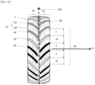
- FIG. 1-B features tread patterns that span the full width of the tread.
- Each motif is made up of two symmetrical bars.
- the axial ends of a bar, I for row R1 and I' for row R2 are positioned relative to the axial ends of the bar at the center of the tread (M' and M).
- the principle of construction of the tread pattern requires starting from a bar in row R1, then positioning the same bar in row R2 by symmetry with respect to the equatorial plane 100 so that the end axial I' or at a given distance R from the end M of the initial strip of row R1.
- FIG. 1-B illustrates the previous construction principle with a sequence of several sculpture patterns made up of the three bar families A, B, C.
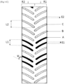
- FIG. 1-C shows the course of the tread of a tire of the invention with three families of strips (A, B, C).
- Strip C has the longest length L2, an average thickness E2, and strip A has the smallest length L1, an average thickness E1.
- the angle ⁇ represents the average inclination of a bar with the circumferential direction.
- the invention has been more particularly studied for an agricultural tire of size 710/70R42.
- two versions were tested: a first with a single-pitch sculpture in accordance with the state of the art, and a second version in accordance with the invention with three families of strips A, B, and C with variable pitches.
- Each bar, A, B, and C is the basic element of the three tread patterns.
- the steps respectively (S, M, L) are associated respectively with the strips (A, B, C) such that S ⁇ M ⁇ L.
- FIG. 1-B One such example of a carving pattern is shown in the Figure 1-B with the two base bars which are symmetrical with respect to the equatorial plane and offset in the circumferential direction.
- the noses of the bars converge towards the center of the tread so as to define the direction of rotation of the tire by taking the shape of a "V" in chevron.
- the rhythm of the impacts of the sculpture on the ground at the entrance to the contact area is punctuated by the order of succession of the motifs. If the patterns are all the same size, they follow one another at a perfectly regular rhythm. A single frequency will then be solicited, which will produce a sound resembling that of a "siren". Having several sizes of patterns makes it possible to scramble the sound signal emitted by the tread pattern of the tire, that is to say to reduce the emergences, to tend towards a white noise.
- Beating also called amplitude modulation, occurs when two sounds that have very similar frequencies are emitted simultaneously. If these sounds are of amplitude comparable, they cancel out each time they are in phase opposition, then add up when they are in phase. This forms an amplitude modulation phenomenon.
- each sculpture pattern is associated with an elementary signal, for example sinusoidal.
- the associated signal is periodic and results from the summation of the elementary signals.
- the optimization of the initial arrangement vis-à-vis the siren and beat noise is carried out by carrying out simulations on different arrangements.
- the spectrum of the signal is analyzed in the frequency domain.
- the criteria for stopping the optimization process are linked to the amplitude of the emergences of siren and beat, as well as to their spread over the frequency axis.
- the total number of tread patterns is 23 pairs of bars arranged according to the sequence: ABBCCBAABAABBCCBCCBAABC, along the circumference of the tire equal to 6465.4 mm .
- the tread pattern of the tire produced therefore comprises 7 A patterns, 9 B patterns and finally 6 C patterns.
- the following table summarizes the characteristics of the bars on at least one row R1 or R2: [Table 1] Number Circumferential length of a Barrette Average strip thickness Circumferential pitch of a pattern Tilt A-patterns 7 307.6 48.7 234.3 47.6° B-patterns 9 332.7 52 275.7 47.6° C-patterns 6 357.8 60.3 334.8 47.6°
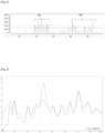
- FIG. 2 represents the harmonic spectrum of the pattern arrangement of the sculptures. It shows two frequency ranges, H1 and H2.
- Block H1 is centered on harmonic n° 23 linked to the number of pairs of bars, and block H2 is linked to each unit bar, ie 46 bars.
- the shape of the spectrum shows the absence of emergences and the spread of the amplitudes of power radiated from the masses H1 and H2 which confirm the optimization of the spectrum linked to the chosen arrangement.
- the maximum height of the strips Hmax is 65 mm, and the angle of inclination ⁇ with the circumferential direction is 47°.
- volume indentation rate TEV is equal to the ratio between the total volume of the grooves separating the bars and the total volume radially between the bottom surface and the running surface, then the volume indentation rate TEV is equal to 80% .
- the tire made in the 710/70 R42 size underwent a noise evaluation test in the passenger compartment.
- the test consists of measuring the noise in the passenger compartment using two microphones positioned at the level of the driver's ears, during passages at constant speeds of 55/50/45/40 km/h on an asphalt road.
- the tire tested is mounted on the rear axle, inflated to a pressure of 1.6 bar, and subjected to a load of 5350 kg. On the front axle the tires are smooth after planing.
- FIG. 3 shows the test result which is the harmonic spectrum of the signal measured in the vehicle cabin.
- the curve C2 in broken lines represents the tire of the invention and that in continuous C1, the reference tire.
- the amplitude of the acoustic power is significantly reduced, thus eliminating the discomfort perceived by the user.
- the invention can easily be extrapolated to tires, for example and in a non-exhaustive manner, which equip utility vehicles for mixed use on asphalt roads, and/or on all-terrain roads.
Landscapes
- Engineering & Computer Science (AREA)
- Mechanical Engineering (AREA)
- Tires In General (AREA)
Claims (9)
- Reifen (1) für ein landwirtschaftliches Fahrzeug, umfassend einen Laufstreifen (10), der dazu bestimmt ist, über eine Lauffläche mit einem Boden in Kontakt zu treten:- wobei der Laufstreifen (10) Reliefelemente (20) oder Stollen (20) umfasst, die wenigstens teilweise durch Rillen (30) voneinander getrennt sind und sich radial nach außen von einer Bodenfläche bis zur Lauffläche über eine radiale Höhe H erstrecken, die wenigstens gleich 30 mm und höchstens gleich der radialen Dicke Hmax des Laufstreifens (10) ist;- wobei die Stollen (20) in zwei umlaufenden Reihen (R1, R2) verteilt sind;
wobei eine erste umlaufende Reihe (R1) von einer Umfangsverteilung wenigstens zweier Stollenfamilien gebildet ist, die periodisch über den Umfang des Reifens verteilt sind;- wobei die Stollen einer ersten Familie in Umfangsrichtung mit einem kürzesten Abstand S verteilt sind und die Stollen einer zweiten Familie in Umfangsrichtung mit einem längsten Abstand L verteilt sind;
wobei jeder Stollen (20) der ersten umlaufenden Reihe (R1) ferner um einen Winkel Ψ im Verhältnis zur Umfangsrichtung (XX') des Reifens geneigt ist;- wobei die zweite umlaufende Reihe (R2) durch eine Symmetrie der ersten umlaufenden Reihe (R1) im Verhältnis zu einer Äquatorialebene (100), die durch den Mittelpunkt des Laufstreifens und senkrecht zur Drehachse (YY') des Reifens verläuft, dann durch einen Drehversatz um einen Winkel θ um die Drehachse (YY') erhalten wird;- wobei der Drehversatz durch einen Überlappungsabstand (R) zwischen den Stollen der ersten umlaufenden Reihe und jenen der zweiten umlaufenden Reihe gekennzeichnet ist, der als der umlaufende Abstand zwischen dem axial äußeren Ende jedes Stollens (20) der ersten umlaufenden Reihe (R1) und dem axial inneren Ende des Stollens (20) der zweiten umlaufenden Reihe (R2) gegenüber in der Drehrichtung des Reifens (1) definiert istdadurch gekennzeichnet, dass das Verhältnis S/L des kürzesten Abstands S der ersten Stollenfamilie zum längsten Abstand L der zweiten Stollenfamilie im Bereich [0.6; 0.8] liegt, und dadurch, dass der Überlappungsabstand R in Umfangsrichtung zwischen der ersten und zweiten umlaufenden Stollenreihe über den gesamten Umfang des Reifens konstant ist. - Reifen (1) nach Anspruch 1, wobei der Überlappungsabstand R zwischen der ersten und zweiten umlaufenden Stollenreihe im Bereich [L/4; L/2] liegt,
- Reifen (1) nach einem der Ansprüche 1 oder 2, wobei der Drehwinkel θ der zweiten umlaufenden Reihe (R2) im Verhältnis zur ersten umlaufenden Reihe (R1) im Bereich [5°; 15°] liegt.
- Reifen (1) nach einem der Ansprüche 1 bis 3, wobei die Stollen der ersten Familie eine mittlere Dicke E1 und die Stollen der zweiten Familie eine mittlere Dicke E2 aufweisen, wobei die relative Dickenvariation (E2- E1/E2) kleiner als oder gleich 25 % ist.
- Reifen (1) nach einem der Ansprüche 1 bis 4, wobei der mittlere Neigungswinkel Ψ jedes Stollens zur Umfangsrichtung (XX') kleiner als oder gleich 50° ist.
- Reifen (1) nach einem der vorhergehenden Ansprüche 1 bis 5, wobei der Laufstreifen wenigstens zwei Stollenreihen mit drei Familien (A, B, C) umfasst, die dem kürzesten Abstand S, dem Zwischenabstand M bzw. dem längsten Abstand L zugeordnet sind, wobei der Zwischenabstand M gleich dem arithmetischen Mittelwert des kürzesten Abstands S und des längsten Abstands L ist.
- Reifen (1) nach einem der Ansprüche 1 bis 6, wobei der Laufstreifen eine Mittenabwicklung im Bereich [6300; 6850] mm aufweist und zwei Reihen von N Stollen aufweist, wobei N von 20 bis 25 beträgt, wobei jede der Reihen drei Stollenfamilien (A, B, C) aufweist, wobei die Anordnung der Stollenfamilien für jede Reihe den folgenden Sequenzen folgt:- N=20, die Sequenz ist: BCCCBBAAAAACBBCABBAA- N=21, die Sequenz ist: AABCBCAACBAABCCCBBBAA- N=22, die Sequenz ist: CCABBBBBAAACCCCBAAAAAB- N=23, die Sequenz ist: ABBCCBAABAABBCCBCCBAABC- N=24, die Sequenz ist: BBCCCBBAAAABCCCAAABBBCAA- N=25, die Sequenz ist: BBCBBAAABCCCBBBAAAAACCCAA
- Reifen (1) nach einem der Ansprüche 1 bis 6, wobei der Laufstreifen eine Mittenabwicklung im Bereich [5500; 6000] mm aufweist und zwei Reihen von N Stollen aufweist, wobei N von 20 bis 25 beträgt, wobei jede der Reihen drei Stollenfamilien (A, B, C) aufweist, wobei die Anordnung der Stollenfamilien für jede Reihe den folgenden Sequenzen folgt:
N=20, die Sequenz ist: BBACBCAAAAABBCCCBAAB- N=21, die Sequenz ist: CCAACBBAABCCCBBBAAAAB- N=22, die Sequenz ist: CCAABABBBBBCCAAAAAABCC- N=23, die Sequenz ist: BAAAAAABCCCBBAAACBBBBCC- N=24, die Sequenz ist: BCCAAAAACCCCBBAABBAACBBB- N=25, die Sequenz ist: BBAACCCAAAAABBBCCCBAAABBC - Reifen (1) nach einem der Ansprüche 1 bis 8, wobei der Laufstreifen eine Volumeneinkerbungsrate TEV aufweist, die gleich dem Verhältnis zwischen dem Gesamtvolumen der Rillen (30), die die Reliefelemente (20) trennen, und dem radial zwischen der Bodenfläche und der Lauffläche enthaltenen Gesamtvolumen ist, wobei die Volumeneinkerbungsrate TEV zwischen 50 % und 80 % beträgt.
Applications Claiming Priority (2)
| Application Number | Priority Date | Filing Date | Title |
|---|---|---|---|
| FR1911506A FR3102093B1 (fr) | 2019-10-16 | 2019-10-16 | PNEUMATIQUE POUR VEHICULE a usage agricole |
| PCT/FR2020/051807 WO2021074517A1 (fr) | 2019-10-16 | 2020-10-13 | Pneumatique pour vehicule a usage agricole |
Publications (2)
| Publication Number | Publication Date |
|---|---|
| EP4045338A1 EP4045338A1 (de) | 2022-08-24 |
| EP4045338B1 true EP4045338B1 (de) | 2023-07-05 |
Family
ID=69810949
Family Applications (1)
| Application Number | Title | Priority Date | Filing Date |
|---|---|---|---|
| EP20801332.6A Active EP4045338B1 (de) | 2019-10-16 | 2020-10-13 | Reifen für ein landwirtschaftliches fahrzeug |
Country Status (5)
| Country | Link |
|---|---|
| US (1) | US12344042B2 (de) |
| EP (1) | EP4045338B1 (de) |
| BR (1) | BR112022005364A2 (de) |
| FR (1) | FR3102093B1 (de) |
| WO (1) | WO2021074517A1 (de) |
Family Cites Families (14)
| Publication number | Priority date | Publication date | Assignee | Title |
|---|---|---|---|---|
| US3603370A (en) | 1969-11-28 | 1971-09-07 | Goodyear Tire & Rubber | Pneumatic tire |
| FR2511952A1 (fr) | 1981-08-31 | 1983-03-04 | Kleber Colombes | Pneumatique pour roue motrice de tracteur agricole ou vehicule similaire |
| US4383567A (en) | 1982-02-05 | 1983-05-17 | The Goodyear Tire & Rubber Company | Pneumatic tractor tire |
| US4534392A (en) | 1984-05-16 | 1985-08-13 | The Goodyear Tire & Rubber Company | Tractor tire |
| US5056573A (en) * | 1990-02-12 | 1991-10-15 | Brien Jimmie P O | Reduced vibration pneumatic tractor tire |
| US5843248A (en) * | 1995-05-19 | 1998-12-01 | The Goodyear Tire & Rubber Company | Radial agricultural tire with a pitched tread |
| BR9602184A (pt) * | 1995-05-19 | 1998-04-07 | Goodyear Tire & Rubber | Pneu agrícola tendo uma carcaça de lona radial um eixo geométrico de rotaç o e uma banda de rodagem anular |
| CA2176267A1 (en) | 1996-03-11 | 1997-09-12 | Mark Leonard Bonko | Pneumatic agricultural tire |
| JP3860306B2 (ja) | 1997-09-17 | 2006-12-20 | 株式会社ブリヂストン | 方向性ラグを備えた農耕用空気入りタイヤ |
| US6651712B1 (en) * | 1999-06-10 | 2003-11-25 | The Goodyear Tire & Rubber Company | Variable pitched tread for ATV tire |
| US6363984B1 (en) * | 1999-10-25 | 2002-04-02 | Kumho & Co, Inc | Tire tread pitch sequencing for reduced noise |
| ITTO20040908A1 (it) | 2004-12-28 | 2005-03-28 | Bridgestone Technical Ct Europ | Pneumatico per uso agricolo |
| CN102245402B (zh) * | 2008-12-12 | 2014-02-05 | 住友橡胶工业株式会社 | 充气轮胎及其制造方法 |
| FR3042199B1 (fr) * | 2015-10-08 | 2017-11-03 | Michelin & Cie | Pneumatique pour vehicule a usage agricole |
-
2019
- 2019-10-16 FR FR1911506A patent/FR3102093B1/fr active Active
-
2020
- 2020-10-13 US US17/769,120 patent/US12344042B2/en active Active
- 2020-10-13 EP EP20801332.6A patent/EP4045338B1/de active Active
- 2020-10-13 BR BR112022005364A patent/BR112022005364A2/pt active Search and Examination
- 2020-10-13 WO PCT/FR2020/051807 patent/WO2021074517A1/fr not_active Ceased
Also Published As
| Publication number | Publication date |
|---|---|
| EP4045338A1 (de) | 2022-08-24 |
| BR112022005364A2 (pt) | 2022-06-14 |
| US20240270025A1 (en) | 2024-08-15 |
| FR3102093B1 (fr) | 2021-09-24 |
| US12344042B2 (en) | 2025-07-01 |
| FR3102093A1 (fr) | 2021-04-23 |
| WO2021074517A1 (fr) | 2021-04-22 |
Similar Documents
| Publication | Publication Date | Title |
|---|---|---|
| EP0282765B1 (de) | Lauffläche für einen Gürtelreifen, dessen Einschnitte bogen- oder winkelförmig verlaufen | |
| FR2956354A1 (fr) | Pneumatique pour vehicules a deux roues comportant une bande de roulement presentant des incisions. | |
| FR2976521A1 (fr) | Procede de detection univoque du seuil d'usure d'un pneumatique | |
| FR2736591A1 (fr) | Enveloppe de bandage pneumatique | |
| FR2954224A1 (fr) | Procede de detection univoque du seuil d'usure d'un pneumatique | |
| FR2954225A1 (fr) | Pneumatique munis de temoins d'usure sonores multiniveaux | |
| EP2509805A1 (de) | Mit kurzen ausgerichteten und kreuzweise angeordneten fasern verstärktes reifenprofil | |
| EP1307350B1 (de) | Motorradreifen mit antischwingungsmittel | |
| FR2976522A1 (fr) | Pneumatique munis de temoins d'usure sonores multiniveaux | |
| EP3946974A1 (de) | Luftreifen mit optimierten kronen- und wulstarchitekturen | |
| WO2012175893A1 (fr) | Pneumatique muni de canaux sonores | |
| EP1354183B1 (de) | Verfahren zur vorhersage des komfortgrades eines fahrzeuges | |
| EP4045338B1 (de) | Reifen für ein landwirtschaftliches fahrzeug | |
| EP3802153B1 (de) | Lauffläche für ein landwirtschaftliches fahrzeug | |
| EP4126566A1 (de) | Reifen mit einer lauffläche mit optimierter griffigkeit auf schneebedecktem grund | |
| WO2003064187A1 (fr) | Sculpture de bande de roulement et methode de construction | |
| EP4126565A1 (de) | Reifen mit optimierter lauffläche in bezug auf die haftung auf trockenem boden | |
| EP2310249B1 (de) | Zum ziehen von maschinen bestimmtes schwerfahrzeug | |
| EP3946977B1 (de) | Lauffläche für ein landwirtschaftliches fahrzeug | |
| FR3060450B1 (fr) | Ensemble pourvu d’un pneumatique a taille tres basse | |
| FR3140305A1 (fr) | Pneumatique comprenant une bande de roulement à usure homogène | |
| WO2025087812A1 (fr) | Pneumatique présentant un compromis de performances avantageux entre adhérence sur neige et résistance au roulement | |
| CA3003081C (fr) | Pneumatique presentant des proprietes d'usure ameliorees | |
| FR3115234A1 (fr) | Pneumatique comportant une bande de roulement constituee de plusieurs melanges elastomeriques | |
| FR3159555A1 (fr) | Pneumatique comprenant une bande de roulement complexe comprenant des découpures pontées et inclinées |
Legal Events
| Date | Code | Title | Description |
|---|---|---|---|
| STAA | Information on the status of an ep patent application or granted ep patent |
Free format text: STATUS: UNKNOWN |
|
| STAA | Information on the status of an ep patent application or granted ep patent |
Free format text: STATUS: THE INTERNATIONAL PUBLICATION HAS BEEN MADE |
|
| PUAI | Public reference made under article 153(3) epc to a published international application that has entered the european phase |
Free format text: ORIGINAL CODE: 0009012 |
|
| STAA | Information on the status of an ep patent application or granted ep patent |
Free format text: STATUS: REQUEST FOR EXAMINATION WAS MADE |
|
| 17P | Request for examination filed |
Effective date: 20220516 |
|
| AK | Designated contracting states |
Kind code of ref document: A1 Designated state(s): AL AT BE BG CH CY CZ DE DK EE ES FI FR GB GR HR HU IE IS IT LI LT LU LV MC MK MT NL NO PL PT RO RS SE SI SK SM TR |
|
| DAV | Request for validation of the european patent (deleted) | ||
| DAX | Request for extension of the european patent (deleted) | ||
| GRAP | Despatch of communication of intention to grant a patent |
Free format text: ORIGINAL CODE: EPIDOSNIGR1 |
|
| STAA | Information on the status of an ep patent application or granted ep patent |
Free format text: STATUS: GRANT OF PATENT IS INTENDED |
|
| INTG | Intention to grant announced |
Effective date: 20230320 |
|
| GRAS | Grant fee paid |
Free format text: ORIGINAL CODE: EPIDOSNIGR3 |
|
| GRAA | (expected) grant |
Free format text: ORIGINAL CODE: 0009210 |
|
| STAA | Information on the status of an ep patent application or granted ep patent |
Free format text: STATUS: THE PATENT HAS BEEN GRANTED |
|
| AK | Designated contracting states |
Kind code of ref document: B1 Designated state(s): AL AT BE BG CH CY CZ DE DK EE ES FI FR GB GR HR HU IE IS IT LI LT LU LV MC MK MT NL NO PL PT RO RS SE SI SK SM TR |
|
| REG | Reference to a national code |
Ref country code: CH Ref legal event code: EP |
|
| REG | Reference to a national code |
Ref country code: AT Ref legal event code: REF Ref document number: 1584528 Country of ref document: AT Kind code of ref document: T Effective date: 20230715 |
|
| REG | Reference to a national code |
Ref country code: DE Ref legal event code: R096 Ref document number: 602020013439 Country of ref document: DE |
|
| REG | Reference to a national code |
Ref country code: IE Ref legal event code: FG4D Free format text: LANGUAGE OF EP DOCUMENT: FRENCH |
|
| REG | Reference to a national code |
Ref country code: LT Ref legal event code: MG9D |
|
| REG | Reference to a national code |
Ref country code: NL Ref legal event code: MP Effective date: 20230705 |
|
| REG | Reference to a national code |
Ref country code: AT Ref legal event code: MK05 Ref document number: 1584528 Country of ref document: AT Kind code of ref document: T Effective date: 20230705 |
|
| PG25 | Lapsed in a contracting state [announced via postgrant information from national office to epo] |
Ref country code: NL Free format text: LAPSE BECAUSE OF FAILURE TO SUBMIT A TRANSLATION OF THE DESCRIPTION OR TO PAY THE FEE WITHIN THE PRESCRIBED TIME-LIMIT Effective date: 20230705 |
|
| PG25 | Lapsed in a contracting state [announced via postgrant information from national office to epo] |
Ref country code: GR Free format text: LAPSE BECAUSE OF FAILURE TO SUBMIT A TRANSLATION OF THE DESCRIPTION OR TO PAY THE FEE WITHIN THE PRESCRIBED TIME-LIMIT Effective date: 20231006 |
|
| PG25 | Lapsed in a contracting state [announced via postgrant information from national office to epo] |
Ref country code: ES Free format text: LAPSE BECAUSE OF FAILURE TO SUBMIT A TRANSLATION OF THE DESCRIPTION OR TO PAY THE FEE WITHIN THE PRESCRIBED TIME-LIMIT Effective date: 20230705 |
|
| PG25 | Lapsed in a contracting state [announced via postgrant information from national office to epo] |
Ref country code: IS Free format text: LAPSE BECAUSE OF FAILURE TO SUBMIT A TRANSLATION OF THE DESCRIPTION OR TO PAY THE FEE WITHIN THE PRESCRIBED TIME-LIMIT Effective date: 20231105 |
|
| PG25 | Lapsed in a contracting state [announced via postgrant information from national office to epo] |
Ref country code: SE Free format text: LAPSE BECAUSE OF FAILURE TO SUBMIT A TRANSLATION OF THE DESCRIPTION OR TO PAY THE FEE WITHIN THE PRESCRIBED TIME-LIMIT Effective date: 20230705 Ref country code: RS Free format text: LAPSE BECAUSE OF FAILURE TO SUBMIT A TRANSLATION OF THE DESCRIPTION OR TO PAY THE FEE WITHIN THE PRESCRIBED TIME-LIMIT Effective date: 20230705 Ref country code: PT Free format text: LAPSE BECAUSE OF FAILURE TO SUBMIT A TRANSLATION OF THE DESCRIPTION OR TO PAY THE FEE WITHIN THE PRESCRIBED TIME-LIMIT Effective date: 20231106 Ref country code: NO Free format text: LAPSE BECAUSE OF FAILURE TO SUBMIT A TRANSLATION OF THE DESCRIPTION OR TO PAY THE FEE WITHIN THE PRESCRIBED TIME-LIMIT Effective date: 20231005 Ref country code: LV Free format text: LAPSE BECAUSE OF FAILURE TO SUBMIT A TRANSLATION OF THE DESCRIPTION OR TO PAY THE FEE WITHIN THE PRESCRIBED TIME-LIMIT Effective date: 20230705 Ref country code: LT Free format text: LAPSE BECAUSE OF FAILURE TO SUBMIT A TRANSLATION OF THE DESCRIPTION OR TO PAY THE FEE WITHIN THE PRESCRIBED TIME-LIMIT Effective date: 20230705 Ref country code: IS Free format text: LAPSE BECAUSE OF FAILURE TO SUBMIT A TRANSLATION OF THE DESCRIPTION OR TO PAY THE FEE WITHIN THE PRESCRIBED TIME-LIMIT Effective date: 20231105 Ref country code: HR Free format text: LAPSE BECAUSE OF FAILURE TO SUBMIT A TRANSLATION OF THE DESCRIPTION OR TO PAY THE FEE WITHIN THE PRESCRIBED TIME-LIMIT Effective date: 20230705 Ref country code: GR Free format text: LAPSE BECAUSE OF FAILURE TO SUBMIT A TRANSLATION OF THE DESCRIPTION OR TO PAY THE FEE WITHIN THE PRESCRIBED TIME-LIMIT Effective date: 20231006 Ref country code: FI Free format text: LAPSE BECAUSE OF FAILURE TO SUBMIT A TRANSLATION OF THE DESCRIPTION OR TO PAY THE FEE WITHIN THE PRESCRIBED TIME-LIMIT Effective date: 20230705 Ref country code: ES Free format text: LAPSE BECAUSE OF FAILURE TO SUBMIT A TRANSLATION OF THE DESCRIPTION OR TO PAY THE FEE WITHIN THE PRESCRIBED TIME-LIMIT Effective date: 20230705 Ref country code: AT Free format text: LAPSE BECAUSE OF FAILURE TO SUBMIT A TRANSLATION OF THE DESCRIPTION OR TO PAY THE FEE WITHIN THE PRESCRIBED TIME-LIMIT Effective date: 20230705 |
|
| PG25 | Lapsed in a contracting state [announced via postgrant information from national office to epo] |
Ref country code: PL Free format text: LAPSE BECAUSE OF FAILURE TO SUBMIT A TRANSLATION OF THE DESCRIPTION OR TO PAY THE FEE WITHIN THE PRESCRIBED TIME-LIMIT Effective date: 20230705 |
|
| REG | Reference to a national code |
Ref country code: DE Ref legal event code: R097 Ref document number: 602020013439 Country of ref document: DE |
|
| PG25 | Lapsed in a contracting state [announced via postgrant information from national office to epo] |
Ref country code: SM Free format text: LAPSE BECAUSE OF FAILURE TO SUBMIT A TRANSLATION OF THE DESCRIPTION OR TO PAY THE FEE WITHIN THE PRESCRIBED TIME-LIMIT Effective date: 20230705 Ref country code: RO Free format text: LAPSE BECAUSE OF FAILURE TO SUBMIT A TRANSLATION OF THE DESCRIPTION OR TO PAY THE FEE WITHIN THE PRESCRIBED TIME-LIMIT Effective date: 20230705 Ref country code: EE Free format text: LAPSE BECAUSE OF FAILURE TO SUBMIT A TRANSLATION OF THE DESCRIPTION OR TO PAY THE FEE WITHIN THE PRESCRIBED TIME-LIMIT Effective date: 20230705 Ref country code: DK Free format text: LAPSE BECAUSE OF FAILURE TO SUBMIT A TRANSLATION OF THE DESCRIPTION OR TO PAY THE FEE WITHIN THE PRESCRIBED TIME-LIMIT Effective date: 20230705 Ref country code: CZ Free format text: LAPSE BECAUSE OF FAILURE TO SUBMIT A TRANSLATION OF THE DESCRIPTION OR TO PAY THE FEE WITHIN THE PRESCRIBED TIME-LIMIT Effective date: 20230705 Ref country code: SK Free format text: LAPSE BECAUSE OF FAILURE TO SUBMIT A TRANSLATION OF THE DESCRIPTION OR TO PAY THE FEE WITHIN THE PRESCRIBED TIME-LIMIT Effective date: 20230705 |
|
| PLBE | No opposition filed within time limit |
Free format text: ORIGINAL CODE: 0009261 |
|
| STAA | Information on the status of an ep patent application or granted ep patent |
Free format text: STATUS: NO OPPOSITION FILED WITHIN TIME LIMIT |
|
| PG25 | Lapsed in a contracting state [announced via postgrant information from national office to epo] |
Ref country code: IT Free format text: LAPSE BECAUSE OF FAILURE TO SUBMIT A TRANSLATION OF THE DESCRIPTION OR TO PAY THE FEE WITHIN THE PRESCRIBED TIME-LIMIT Effective date: 20230705 Ref country code: MC Free format text: LAPSE BECAUSE OF FAILURE TO SUBMIT A TRANSLATION OF THE DESCRIPTION OR TO PAY THE FEE WITHIN THE PRESCRIBED TIME-LIMIT Effective date: 20230705 |
|
| REG | Reference to a national code |
Ref country code: CH Ref legal event code: PL |
|
| 26N | No opposition filed |
Effective date: 20240408 |
|
| REG | Reference to a national code |
Ref country code: BE Ref legal event code: MM Effective date: 20231031 |
|
| PG25 | Lapsed in a contracting state [announced via postgrant information from national office to epo] |
Ref country code: LU Free format text: LAPSE BECAUSE OF NON-PAYMENT OF DUE FEES Effective date: 20231013 |
|
| PG25 | Lapsed in a contracting state [announced via postgrant information from national office to epo] |
Ref country code: LU Free format text: LAPSE BECAUSE OF NON-PAYMENT OF DUE FEES Effective date: 20231013 |
|
| PG25 | Lapsed in a contracting state [announced via postgrant information from national office to epo] |
Ref country code: CH Free format text: LAPSE BECAUSE OF NON-PAYMENT OF DUE FEES Effective date: 20231031 |
|
| PG25 | Lapsed in a contracting state [announced via postgrant information from national office to epo] |
Ref country code: CH Free format text: LAPSE BECAUSE OF NON-PAYMENT OF DUE FEES Effective date: 20231031 Ref country code: SI Free format text: LAPSE BECAUSE OF FAILURE TO SUBMIT A TRANSLATION OF THE DESCRIPTION OR TO PAY THE FEE WITHIN THE PRESCRIBED TIME-LIMIT Effective date: 20230705 |
|
| PG25 | Lapsed in a contracting state [announced via postgrant information from national office to epo] |
Ref country code: BE Free format text: LAPSE BECAUSE OF NON-PAYMENT OF DUE FEES Effective date: 20231031 |
|
| PG25 | Lapsed in a contracting state [announced via postgrant information from national office to epo] |
Ref country code: IE Free format text: LAPSE BECAUSE OF NON-PAYMENT OF DUE FEES Effective date: 20231013 |
|
| PG25 | Lapsed in a contracting state [announced via postgrant information from national office to epo] |
Ref country code: IE Free format text: LAPSE BECAUSE OF NON-PAYMENT OF DUE FEES Effective date: 20231013 |
|
| PG25 | Lapsed in a contracting state [announced via postgrant information from national office to epo] |
Ref country code: BG Free format text: LAPSE BECAUSE OF FAILURE TO SUBMIT A TRANSLATION OF THE DESCRIPTION OR TO PAY THE FEE WITHIN THE PRESCRIBED TIME-LIMIT Effective date: 20230705 |
|
| PG25 | Lapsed in a contracting state [announced via postgrant information from national office to epo] |
Ref country code: BG Free format text: LAPSE BECAUSE OF FAILURE TO SUBMIT A TRANSLATION OF THE DESCRIPTION OR TO PAY THE FEE WITHIN THE PRESCRIBED TIME-LIMIT Effective date: 20230705 |
|
| GBPC | Gb: european patent ceased through non-payment of renewal fee |
Effective date: 20241013 |
|
| PG25 | Lapsed in a contracting state [announced via postgrant information from national office to epo] |
Ref country code: GB Free format text: LAPSE BECAUSE OF NON-PAYMENT OF DUE FEES Effective date: 20241013 |
|
| PG25 | Lapsed in a contracting state [announced via postgrant information from national office to epo] |
Ref country code: CY Free format text: LAPSE BECAUSE OF FAILURE TO SUBMIT A TRANSLATION OF THE DESCRIPTION OR TO PAY THE FEE WITHIN THE PRESCRIBED TIME-LIMIT; INVALID AB INITIO Effective date: 20201013 |
|
| PG25 | Lapsed in a contracting state [announced via postgrant information from national office to epo] |
Ref country code: HU Free format text: LAPSE BECAUSE OF FAILURE TO SUBMIT A TRANSLATION OF THE DESCRIPTION OR TO PAY THE FEE WITHIN THE PRESCRIBED TIME-LIMIT; INVALID AB INITIO Effective date: 20201013 |
|
| PG25 | Lapsed in a contracting state [announced via postgrant information from national office to epo] |
Ref country code: TR Free format text: LAPSE BECAUSE OF FAILURE TO SUBMIT A TRANSLATION OF THE DESCRIPTION OR TO PAY THE FEE WITHIN THE PRESCRIBED TIME-LIMIT Effective date: 20230705 |
|
| PGFP | Annual fee paid to national office [announced via postgrant information from national office to epo] |
Ref country code: DE Payment date: 20251021 Year of fee payment: 6 |
|
| PGFP | Annual fee paid to national office [announced via postgrant information from national office to epo] |
Ref country code: FR Payment date: 20251030 Year of fee payment: 6 |