EP4045260B1 - Verfahren zum herstellen eines geschäumten kunststoffformkörpers mit einem filmschichtüberzug - Google Patents
Verfahren zum herstellen eines geschäumten kunststoffformkörpers mit einem filmschichtüberzug Download PDFInfo
- Publication number
- EP4045260B1 EP4045260B1 EP20792957.1A EP20792957A EP4045260B1 EP 4045260 B1 EP4045260 B1 EP 4045260B1 EP 20792957 A EP20792957 A EP 20792957A EP 4045260 B1 EP4045260 B1 EP 4045260B1
- Authority
- EP
- European Patent Office
- Prior art keywords
- tool
- cavity
- granulate
- mold
- film layer
- Prior art date
- Legal status (The legal status is an assumption and is not a legal conclusion. Google has not performed a legal analysis and makes no representation as to the accuracy of the status listed.)
- Active
Links
Images

Classifications
-
- B—PERFORMING OPERATIONS; TRANSPORTING
- B29—WORKING OF PLASTICS; WORKING OF SUBSTANCES IN A PLASTIC STATE IN GENERAL
- B29C—SHAPING OR JOINING OF PLASTICS; SHAPING OF MATERIAL IN A PLASTIC STATE, NOT OTHERWISE PROVIDED FOR; AFTER-TREATMENT OF THE SHAPED PRODUCTS, e.g. REPAIRING
- B29C37/00—Component parts, details, accessories or auxiliary operations, not covered by group B29C33/00 or B29C35/00
- B29C37/0025—Applying surface layers, e.g. coatings, decorative layers, printed layers, to articles during shaping, e.g. in-mould printing
- B29C37/0028—In-mould coating, e.g. by introducing the coating material into the mould after forming the article
- B29C37/0032—In-mould coating, e.g. by introducing the coating material into the mould after forming the article the coating being applied upon the mould surface before introducing the moulding compound, e.g. applying a gelcoat
-
- B—PERFORMING OPERATIONS; TRANSPORTING
- B29—WORKING OF PLASTICS; WORKING OF SUBSTANCES IN A PLASTIC STATE IN GENERAL
- B29C—SHAPING OR JOINING OF PLASTICS; SHAPING OF MATERIAL IN A PLASTIC STATE, NOT OTHERWISE PROVIDED FOR; AFTER-TREATMENT OF THE SHAPED PRODUCTS, e.g. REPAIRING
- B29C44/00—Shaping by internal pressure generated in the material, e.g. swelling or foaming ; Producing porous or cellular expanded plastics articles
- B29C44/02—Shaping by internal pressure generated in the material, e.g. swelling or foaming ; Producing porous or cellular expanded plastics articles for articles of definite length, i.e. discrete articles
- B29C44/04—Shaping by internal pressure generated in the material, e.g. swelling or foaming ; Producing porous or cellular expanded plastics articles for articles of definite length, i.e. discrete articles consisting of at least two parts of chemically or physically different materials, e.g. having different densities
- B29C44/06—Making multilayered articles
-
- B—PERFORMING OPERATIONS; TRANSPORTING
- B29—WORKING OF PLASTICS; WORKING OF SUBSTANCES IN A PLASTIC STATE IN GENERAL
- B29C—SHAPING OR JOINING OF PLASTICS; SHAPING OF MATERIAL IN A PLASTIC STATE, NOT OTHERWISE PROVIDED FOR; AFTER-TREATMENT OF THE SHAPED PRODUCTS, e.g. REPAIRING
- B29C44/00—Shaping by internal pressure generated in the material, e.g. swelling or foaming ; Producing porous or cellular expanded plastics articles
- B29C44/02—Shaping by internal pressure generated in the material, e.g. swelling or foaming ; Producing porous or cellular expanded plastics articles for articles of definite length, i.e. discrete articles
- B29C44/08—Shaping by internal pressure generated in the material, e.g. swelling or foaming ; Producing porous or cellular expanded plastics articles for articles of definite length, i.e. discrete articles using several expanding or moulding steps
-
- B—PERFORMING OPERATIONS; TRANSPORTING
- B29—WORKING OF PLASTICS; WORKING OF SUBSTANCES IN A PLASTIC STATE IN GENERAL
- B29C—SHAPING OR JOINING OF PLASTICS; SHAPING OF MATERIAL IN A PLASTIC STATE, NOT OTHERWISE PROVIDED FOR; AFTER-TREATMENT OF THE SHAPED PRODUCTS, e.g. REPAIRING
- B29C44/00—Shaping by internal pressure generated in the material, e.g. swelling or foaming ; Producing porous or cellular expanded plastics articles
- B29C44/34—Auxiliary operations
- B29C44/3415—Heating or cooling
-
- B—PERFORMING OPERATIONS; TRANSPORTING
- B29—WORKING OF PLASTICS; WORKING OF SUBSTANCES IN A PLASTIC STATE IN GENERAL
- B29C—SHAPING OR JOINING OF PLASTICS; SHAPING OF MATERIAL IN A PLASTIC STATE, NOT OTHERWISE PROVIDED FOR; AFTER-TREATMENT OF THE SHAPED PRODUCTS, e.g. REPAIRING
- B29C44/00—Shaping by internal pressure generated in the material, e.g. swelling or foaming ; Producing porous or cellular expanded plastics articles
- B29C44/34—Auxiliary operations
- B29C44/36—Feeding the material to be shaped
- B29C44/38—Feeding the material to be shaped into a closed space, i.e. to make articles of definite length
- B29C44/44—Feeding the material to be shaped into a closed space, i.e. to make articles of definite length in solid form
- B29C44/445—Feeding the material to be shaped into a closed space, i.e. to make articles of definite length in solid form in the form of expandable granules, particles or beads
-
- B—PERFORMING OPERATIONS; TRANSPORTING
- B29—WORKING OF PLASTICS; WORKING OF SUBSTANCES IN A PLASTIC STATE IN GENERAL
- B29C—SHAPING OR JOINING OF PLASTICS; SHAPING OF MATERIAL IN A PLASTIC STATE, NOT OTHERWISE PROVIDED FOR; AFTER-TREATMENT OF THE SHAPED PRODUCTS, e.g. REPAIRING
- B29C37/00—Component parts, details, accessories or auxiliary operations, not covered by group B29C33/00 or B29C35/00
- B29C37/0025—Applying surface layers, e.g. coatings, decorative layers, printed layers, to articles during shaping, e.g. in-mould printing
- B29C37/0028—In-mould coating, e.g. by introducing the coating material into the mould after forming the article
- B29C2037/0039—In-mould coating, e.g. by introducing the coating material into the mould after forming the article the coating being applied in powder or particle form
-
- B—PERFORMING OPERATIONS; TRANSPORTING
- B29—WORKING OF PLASTICS; WORKING OF SUBSTANCES IN A PLASTIC STATE IN GENERAL
- B29K—INDEXING SCHEME ASSOCIATED WITH SUBCLASSES B29B, B29C OR B29D, RELATING TO MOULDING MATERIALS OR TO MATERIALS FOR MOULDS, REINFORCEMENTS, FILLERS OR PREFORMED PARTS, e.g. INSERTS
- B29K2023/00—Use of polyalkenes or derivatives thereof as moulding material
- B29K2023/04—Polymers of ethylene
- B29K2023/06—PE, i.e. polyethylene
-
- B—PERFORMING OPERATIONS; TRANSPORTING
- B29—WORKING OF PLASTICS; WORKING OF SUBSTANCES IN A PLASTIC STATE IN GENERAL
- B29K—INDEXING SCHEME ASSOCIATED WITH SUBCLASSES B29B, B29C OR B29D, RELATING TO MOULDING MATERIALS OR TO MATERIALS FOR MOULDS, REINFORCEMENTS, FILLERS OR PREFORMED PARTS, e.g. INSERTS
- B29K2025/00—Use of polymers of vinyl-aromatic compounds or derivatives thereof as moulding material
- B29K2025/04—Polymers of styrene
- B29K2025/06—PS, i.e. polystyrene
-
- B—PERFORMING OPERATIONS; TRANSPORTING
- B29—WORKING OF PLASTICS; WORKING OF SUBSTANCES IN A PLASTIC STATE IN GENERAL
- B29K—INDEXING SCHEME ASSOCIATED WITH SUBCLASSES B29B, B29C OR B29D, RELATING TO MOULDING MATERIALS OR TO MATERIALS FOR MOULDS, REINFORCEMENTS, FILLERS OR PREFORMED PARTS, e.g. INSERTS
- B29K2075/00—Use of PU, i.e. polyureas or polyurethanes or derivatives thereof, as moulding material
-
- B—PERFORMING OPERATIONS; TRANSPORTING
- B29—WORKING OF PLASTICS; WORKING OF SUBSTANCES IN A PLASTIC STATE IN GENERAL
- B29K—INDEXING SCHEME ASSOCIATED WITH SUBCLASSES B29B, B29C OR B29D, RELATING TO MOULDING MATERIALS OR TO MATERIALS FOR MOULDS, REINFORCEMENTS, FILLERS OR PREFORMED PARTS, e.g. INSERTS
- B29K2101/00—Use of unspecified macromolecular compounds as moulding material
- B29K2101/12—Thermoplastic materials
-
- B—PERFORMING OPERATIONS; TRANSPORTING
- B29—WORKING OF PLASTICS; WORKING OF SUBSTANCES IN A PLASTIC STATE IN GENERAL
- B29K—INDEXING SCHEME ASSOCIATED WITH SUBCLASSES B29B, B29C OR B29D, RELATING TO MOULDING MATERIALS OR TO MATERIALS FOR MOULDS, REINFORCEMENTS, FILLERS OR PREFORMED PARTS, e.g. INSERTS
- B29K2105/00—Condition, form or state of moulded material or of the material to be shaped
- B29K2105/04—Condition, form or state of moulded material or of the material to be shaped cellular or porous
-
- B—PERFORMING OPERATIONS; TRANSPORTING
- B29—WORKING OF PLASTICS; WORKING OF SUBSTANCES IN A PLASTIC STATE IN GENERAL
- B29K—INDEXING SCHEME ASSOCIATED WITH SUBCLASSES B29B, B29C OR B29D, RELATING TO MOULDING MATERIALS OR TO MATERIALS FOR MOULDS, REINFORCEMENTS, FILLERS OR PREFORMED PARTS, e.g. INSERTS
- B29K2105/00—Condition, form or state of moulded material or of the material to be shaped
- B29K2105/04—Condition, form or state of moulded material or of the material to be shaped cellular or porous
- B29K2105/048—Expandable particles, beads or granules
-
- B—PERFORMING OPERATIONS; TRANSPORTING
- B29—WORKING OF PLASTICS; WORKING OF SUBSTANCES IN A PLASTIC STATE IN GENERAL
- B29L—INDEXING SCHEME ASSOCIATED WITH SUBCLASS B29C, RELATING TO PARTICULAR ARTICLES
- B29L2009/00—Layered products
- B29L2009/005—Layered products coated
Definitions
- the invention relates to a method for producing a foamed plastic body with a film layer coating using a tool mold with at least one tool cavity for forming a shaping mold cavity.
- the mold cavity which is defined by the at least one mold cavity of the mold, determines the geometry of the foamed plastic molded body to be produced.
- the plastic molded body produced in the mold can be ejected from the mold or molded out of it by opening the mold after cooling.
- Such a device and a method for producing a foamed plastic molded body are known, for example, from DE 10 2009 006 507 B3 became known.
- the foamed plastic moldings known from the state of the art do not have a closed or continuous surface after completion of the above-described manufacturing process. Rather, due to the expansion process, there are still microcavities on the surface of the foamed plastic moldings into which fluids, for example, can enter.
- Another disadvantage is that due to the aforementioned cavities, the plastic moldings do not have a closed, flat surface structure and are therefore not immediately suitable for painting the moldings for use in automotive technology, for example.
- the foamed plastic moldings known to date only have the color of the expanded or foamed plastic granulate that is used as the starting material.
- a process for molding plastic from a particulate plastic material and a heat-activated, expandable foam filling material comprises the following steps comprises: (i) providing first and second molded parts; (ii) heating the molded parts at least at their surface portions to a temperature of about 100 to about 500 degrees Celsius to render the particles meltable or sinterable; (iii) contacting the molded parts with plastic particulate material; (iv) contacting the expandable foam plastic filler material with the particles; (v) melting or sintering at least a portion of the plastic particles on each molded part to form a molded skin of about 0.001 cm to 3.0 cm; (vi) bringing the heated molded parts together such that heat from the heated molded parts activates the expandable foam to form a composite sandwich.
- the JP S63 312248 A describes the manufacture of a part for a vehicle interior which is produced by laminating a skin made of a synthetic resin, a foamed layer and a fiber-containing layered base material which are bonded together and formed into a predetermined shape.
- the GB 2 460 838 A discloses a machine and method for molding plastic articles and includes a pair of hingedly connected cavity molds which are heated and cooled and which can be clamped together.
- the method involves introducing a plastic particulate material into each mold when they are in the open position and heating the molds to form a plastic skin which lines each mold.
- An expandable filler material is then introduced into one mold and the two molds are closed to form a completely enclosed cavity.
- the plastic skins in the two molds bond together to form a continuous plastic shell which completely encloses the filler material.
- the object of the present invention is to propose a simplified manufacturing process for producing a foamed plastic molded body with a film layer coating, which can be carried out more cost-effectively and with a reduced production time and with which the properties of the plastic molded body can also be specifically adjusted to the intended purpose.
- process step E the tool mold and in particular the heated at least one tool cavity of the tool mold is cooled down to the demolding temperature and then the plastic molded body with film layer coating is ejected or molded out of the tool mold as a tool-falling component.
- the granulate applied in process step B) is the desired material from which the to be formed is formed for the foamed plastic molded body.
- process step A) the at least one tool cavity is heated to at least the melting temperature of the granulate applied in process step B) in order to form a liquid film layer in process step C), which is formed from the melted granulate.
- the temperature of the at least one tool cavity is guided or controlled during the implementation of the process in such a way that it is essentially at least above the melting temperature of the applied granulate during the entire period of implementation of at least process steps B) to D).
- the method according to the invention has the advantage that a closed film layer coating can be produced on the plastic molded body using the tools already available, in particular the multi-part tool molds.
- the additional devices previously required according to the state of the art for applying in particular a plastic film layer or textile layers with a plastic layer to create a coating on the plastic molded body become obsolete.
- a particular advantage of the method according to the invention is that it can be seamlessly integrated into the existing production process of the manufacturing process or directly connected to it, which brings with it a significant time saving and an increase in effectiveness.
- a continuous film layer of the granulate material with a defined film layer thickness is formed in the heated tool cavity, whereby the continuous film layer is present in the melted or liquid state in the heated tool cavity after completion of process step C).
- the melted film layer is applied in the liquid state to the foamed plastic molding at least partially on its surface to form a closed film layer coating on the surface of the plastic molding and melts or solidifies directly on the previous surface of the plastic molding.
- the film layer can cover the entire surface of the foamed plastic molding or alternatively, only partial surface areas of the plastic molded body can be covered as a closed film layer.
- the method according to the invention also has the advantage that no burrs are formed on the plastic molded body produced, which means that no further reworking is required on the finished parts produced, for example to remove a sprue or a protruding burr.
- the actual plastic molded body is initially produced using a foaming or expansion process, as is known, for example, from the prior art, then the tool mold is opened, the foamed plastic molded body remaining in at least one first tool cavity and the process steps A) to E) are subsequently carried out on at least one second, opposite tool cavity, the application of the film layer according to process step D) being carried out by closing the tool mold again around the already expanded plastic molded body and the cooling in process step E) of the at least one tool cavity taking place in the closed mold state.
- a foaming or expansion process as is known, for example, from the prior art
- the aforementioned embodiment of the production method according to the invention has the advantage that the production of the film layer coating is carried out immediately after the process already known from the prior art for producing foamed plastic molded bodies using the known expansion processes and the application of the film layer is made possible according to the invention using the already existing tool mold. Due to the production and application of the film layer immediately following the manufacture of the plastic molded body, a good bonding or adhesion of the film layer to the plastic molded body can be achieved, since interim contamination of the bonding surface of the plastic molded body is avoided.
- the plastic molded body can be produced using an expansion process in the cavity of the mold using all expandable particle foams such as: EPS (expandable polystyrene), EPP (expandable polypropylene), EPE (expandable polyethylene), expandable thermoplastic polyurethane (E-TPU) and graphite or carbon-containing polystyrene.
- EPS expanded polystyrene
- EPP expanded polypropylene
- EPE expanded polyethylene
- E-TPU expandable thermoplastic polyurethane
- graphite or carbon-containing polystyrene graphite or carbon-containing polystyrene.
- it can also be provided to produce the plastic molded body using an expansion process in a first mold and then to carry out the process steps according to the invention on a second mold.
- the process steps A) to C) are first carried out, then the tool mold is closed, and the mold cavity of the tool mold is filled with a first expandable plastic granulate or foam beads and then the first expandable plastic granulate or the foam beads are expanded in the mold cavity, wherein the process step D) takes place in that the plastic molded body is expanded against the liquid film layer formed on the at least one tool cavity and immediately fuses with it.
- the expansion process of the first expandable plastic granulate is terminated prematurely or stopped prematurely after a defined period of time, whereby only a portion of the plastic granulate or foam beads are expanded.
- the portion of the first plastic granulate that has not yet melted or expanded is then removed from the mold cavity, whereby only a layer of the first expanded plastic granulate adheres to the film layer.
- the intermediate article obtained can be left in the mold cavity to carry out further processing steps or can be molded out of it.
- the mold cavity can be filled with a second expandable plastic granulate or Foam beads are filled, which are then expanded to form the plastic molded body.
- the described method can be used to produce a plastic molded body which has a film layer, wherein underneath this film layer there is a layer of first expanded plastic particles or foam beads of a first material, which is fused to the film layer or bonded to it, and underneath there is a second layer of second expanded plastic particles or foam beads, which is made of a second material and which is at least bonded to the first layer or bonded to it.
- the described method makes it possible to produce a plastic molded body which consists of two different foamed granules.
- the first expandable plastic granule can be selected such that it produces a local foam body with a low density and simultaneously high elasticity and the second granule produces a local foam body with a higher density and lower elasticity than the first expandable plastic granule.
- a resulting foamed plastic molded body can be obtained which has a soft and stretchable surface below the film layer coating in the area of the surface, wherein the lower local foam area is structurally stable and non-deformable.
- the first expandable plastic granulate can have a higher stiffness and a higher density than the second expandable plastic granulate, such that an article with a very stiff surface can be obtained while at the same time having a reduced weight.
- the provision of a first foam layer, formed from an expandable plastic granulate with a high stiffness and at the same time a high density, has the advantage that film coatings with a low film thickness can be realized.
- the resulting local properties of the foam layers that form the plastic molded body can be specifically influenced. Furthermore, it can be provided that by repeating the process, more than two different expandable plastic granules are used to form the plastic molded body. In a preferred embodiment, it can accordingly be provided that, while leaving the intermediate article in the mold cavity after removing a non-expanded portion of the first plastic granule, the mold cavity is filled with at least two further expandable plastic granules or foam beads, which are then expanded to form the plastic molded body.
- the expansion process of the further expandable plastic granules is terminated prematurely or stopped prematurely after a defined period of time, whereby only a portion of the further plastic granules or foam beads are expanded.
- the portion of the further plastic granules that has not yet melted or expanded can then be removed from the mold cavity, whereby layers of defined thicknesses of the further expanded plastic granules can be produced.
- the described method makes it possible to produce a plastic molded body which has a film layer, wherein underneath this film layer there is a layer of first expanded plastic particles or foam beads of a first material, which is fused to the film layer or bonded to it and underneath there is any number of further layers of further expanded plastic particles or foam beads, which can be formed from other materials and which are bonded to or bonded to at least the first layer.
- the described method makes it possible to produce a plastic molded body with a film layer and any number of underlying layers of expanded plastic particles Consequently, a so-called multilayer molded body with in particular 3 to 6 layers can be produced.
- the granulate in process step B) is applied beyond the area of the at least one tool cavity onto the surface of the multi-part tool mold and that at least one part of the multi-part tool mold comprises a sealing ring which, when the tool mold is closed, raises the granulate outside the area of the at least one tool cavity to form a bead in the edge area of the at least one first and/or second tool cavity.
- the sealing ring is arranged on a first part of the tool mold and, when the tool mold is closed, sweeps over the surrounding area of the opposite tool cavity of the at least one second part of the tool mold.
- the granulate applied outside the tool cavity is pushed together in the melted state by the movement of the sealing ring relative to the opposite tool cavity and forms a bead delimiting the opposite tool cavity.
- the peripheral edge of the film layer coating is better connected to the foam body by means of the bead, in such a way that detachment in the edge areas of the film layer coating can be avoided.
- the tool shape opposite the sealing ring is particularly preferably designed to be conical, in such a way that the sealing ring can be better inserted into the opposite tool shape.
- the granulate for the film layer coating in process step B) is applied to the at least one tool cavity by means of a spray gun.
- the at least one tool cavity to be heated in process step A) initiates a Heating medium is heated via corresponding heating channels in at least one tool cavity.
- Heated oil, water or a water vapor mixture can be used as the heating medium.
- the at least one tool cavity can be heated by at least one active heating device, such as an electrical heating element, such as in particular a resistance heating element, a PTC element, or an inductive heating element.
- an electrical heating element such as in particular a resistance heating element, a PTC element, or an inductive heating element.
- it can also be provided to heat the at least one tool cavity directly with an external heat source, such as a hot air stream.
- an external heat source such as a hot air stream.
- the at least one tool cavity can be heated via a radiant heater, such as an infrared radiator, or alternatively also heated via at least one heating burner.
- a radiant heater such as an infrared radiator
- the at least one tool cavity to be heated is heated to at least one temperature above the melting temperature of the applied granulate, in particular to a temperature in the range of 80°C to 260°C.
- thermoplastic granulate in process step B) a powdered thermoplastic granulate is applied to the at least one tool cavity.
- the thermoplastic granulate can then be melted by heating the tool cavity, whereby a continuous melted layer of the thermoplastic is present in the tool cavity.
- the granules can also be mixed with additives and applied to at least one tool cavity.
- Glass fibers and/or carbon fibers in particular could be used as granulated additives.
- a layer of a fleece or a textile is inserted at least in partial areas of the surface of the at least one tool cavity and is preferably embedded in the liquid film layer or saturated by it.
- the inserted layers can particularly preferably have defined outer contours and dimensions.
- thermoplastic granulate with a defined RAL color can be applied to the at least one tool cavity, whereby a film coating can be produced in a desired defined RAL color.
- plastic granulates with special properties can be used, such as with dissipative properties, flame resistance, suitability for food, resistance to UV radiation, resistance to heat, increased water resistance, increased dielectric strength, increased abrasion resistance.
- a plastic can be used for the film layer coating, which forms a material bond with the plastic molded body. This makes it possible to continue to design the plastic molded body produced with the desired properties.
- the plastic molded body and the film layer coating are made of the same thermoplastic to create a monomaterial composite, for example a combination of the plastics PP with EPP or PS with EPS can be used. Due to the monomaterial composite, the plastic molded body produced with film layer coating can be recycled better due to the uniform material.
- At least one tool cavity with a defined surface texture can be used, which causes a defined surface feature of the film layer.
- the surface of the film layer coating can be equipped with defined textures, extremely smooth or rough surfaces with defined roughnesses or Velcro surfaces.
- a powdered polypropylene (PP) is applied to the at least one tool cavity.
- process step B) granulate is only applied proportionately to defined partial areas of the at least one tool cavity in order to form at least one regional film layer, wherein in particular partial areas of the at least one tool cavity can be covered in order to prevent granulate application there in process step B).
- the granulate is applied in different sub-areas of the tool cavity with defined different layer thicknesses, such that a film layer coating with locally different film layer thicknesses can be produced on the foamed plastic molded body.
- the aforementioned method makes it possible for the first time to specifically create surface areas with different strengths or bending stiffnesses in the film layer coating. In particular, it is possible to introduce weakened areas into the surface, which, for example, bring about a defined deformation behavior when the plastic molded body is used in the automotive sector, for example in the event of an impact.
- a granulate with a layer thickness in the range of 0.05 mm up to 2 mm can be provided.
- the layer thickness of the granulate can be adjusted depending on the expanded plastic granulate underneath.
- step E) the at least one tool cavity to be cooled is cooled convectively and/or conductively.
- the at least one tool cavity to be cooled is cooled by passing a cooling medium through channels of the at least one tool cavity.
- the cooling medium supplied can be, for example, a cooling liquid, in particular oil, cooling air or cooling water.
- the at least one tool cavity to be cooled is cooled by spraying a cooling medium onto at least one tool cavity to be cooled via at least one nozzle device; in particular, it can be provided that water in the liquid state is sprayed onto the at least one tool cavity to be cooled via a plurality of nozzle devices, in particular atomizing nozzles.
- the temperature of the at least one tool cavity to be heated in process step A) is monitored by means of a temperature sensor.
- the temperature sensor can also preferably be used to monitor the desired process temperatures during the entire manufacturing process or in defined process steps and to control them in a targeted manner depending on the measured values.
- the temperature sensor can be used to control the supply of heating medium or, alternatively, the electrical nozzle devices.
- At least one particle foam granulate is fed into the mold via at least one injector device.
- the mold can also be filled locally with different expandable plastic granulates via several injector devices.
- the invention can be provided to carry out the method steps A) to C) on at least one external tool cavity, which is brought together with the tool mold in method steps D) and E) via a displacement to form the mold cavity.
- a rotary table tool with several tool cavities can be used according to the invention.
- a square tool with dimensions of 370 ⁇ 370 ⁇ 60 mm was used to produce sheets by the steam chamber method based on EPP - expanded polypropylene foam particles (trade name Eperan-PP VB45, M30 and VB15 from Kaneka Belgium NV).
- the sheets were stabilized for 24 hours in an oven at 80°C and stored at ambient conditions (23°C - 50% relative humidity).
- a circular heating plate was electrically heated to a temperature of 220°C, a granulate (polypropylene "Gray EX1Y 1876" from Axalta Coating Systems GmbH) was sprayed onto the heated sheet and melted.
- the EPP sheet was pressed onto the layer of melted granulate, the sheet was cooled by air and as a result a film-coated foamed plastic part was obtained.
- a cavity of a tool for producing bowls (example 4) and a cavity of a tool for producing an A-pillar panel for vehicles (example 5) were heated to 185°C and 180°C respectively using Variotherm technology.
- Variotherm technology is a heating and cooling system that can be used to precisely control the temperature in all areas of a tool.
- the tool cavity does not necessarily have to be integrated into the steam chamber of the molding machine.
- a granulate polypropylene "Black EX1Y 1886" or "EX1Y 1886 Blue 565" from Axalta Coating Systems GmbH) was sprayed onto the heated cavity and melted.
- EPP - expanded polypropylene foam particles (trademarks "Eperan-PP MN20” and “Eperan-PP VB 20” from Kaneka Belgium N.V.) and the steam chamber process was applied. In both cases, a foamed plastic part could be produced that was partially 100% covered with a film layer in the desired areas.
- a vehicle A-pillar panel was manufactured using the steam chamber process based on EPP - expanded polypropylene foam particles (trademarks Eperan-PP VB20 and M30 from Kaneka Belgium N.V.). The A-pillar panel was stabilized for 24 hours in an oven at 80°C and stored at ambient conditions (23°C - 50% relative humidity). A cavity of the A-pillar panel was heated to 180°C using Variotherm technology, a granulate (polypropylene "Black EX1Y 1886" from Axalta GmbH) was sprayed onto the heated cavity and melted. The foamed A-pillar panel was pressed onto the layer of melted granulate, the plate was cooled and a foamed plastic part with a film coating could be manufactured. This method has proven to be very practical for small series.
- the cavity of the A-pillar panel was heated to 180°C using Variotherm technology, a granulate (polypropylene "Black EX1Y 1886" from Axalta Coating Systems GmbH) was sprayed onto the heated cavity and melted.
- the tool with the hot cavity was closed and expanded polypropylene foam particles (trademark EPERAN-PP M30 from Kaneka Belgium N.V.) of type X were filled into the tool, which then partially adhered to the melted film layer and formed a first layer with a low density (soft). The non-adhering, excess foam particles were sucked out of the cavity.
- Foam particles of type Y brand EPERAN-PP VB20 from Kaneka Belgium NV
- a foamed plastic part could be manufactured that was partially 100% covered with a film layer in the desired areas.
- the cavity of the A-pillar panel was heated to 180°C using Variotherm technology, a granulate (polypropylene "Black EX1Y 1886" from Axalta Coating Systems GmbH) was sprayed onto the heated cavity and melted.
- the tool with the hot cavity was closed and expanded polypropylene foam particles (trademark EPERAN-PP M30 from Kaneka Belgium NV) of type X were filled into the tool, which then partially adhered to the melted film layer and formed a first layer with a low density (soft).
- the cavity was cooled. The non-adhering, excess expanded polypropylene foam particles were sucked out of the tool and the film layer with the layer formed from adhering foam particles of type X was removed from the tool and stored.
- the film layer with the melted layer of foam particles was reinserted into a tool.
- Expanded polypropylene foam particles of type Y (trademark Eperan-PP VB20 from Kaneka Belgium NV) were blown into the tool and the steam chamber process was applied. It was possible to produce a foamed plastic part that was partially 100% covered with a film layer in the desired areas.
- type X and type Y two layers with different densities (soft and hard) could also be realized.
- the tool cavity does not necessarily have to be integrated into the steam chamber of the molding machine.
- Spray system from Nordson Deutschland GmbH Powder is transferred from a storage or feed container using dense phase pump technology to a powder spray gun (Encore HD system), which applies the powder with or without electrostatic charging.
- the granulate can also be melted on a cavity copy over the entire surface or part of the surface outside the molding machine. This enables shorter cycle times and also the coating of thick foamed plastic parts if steam nozzles are required on all sides.
- a 1% water-based soap solution was prepared by adding 25 g of dishwashing detergent (trademark "Dreft-Original” of Procter & Gamble) to 2500 ml of water at a temperature of 25°C.
- a foam part in the form of a cylindrical bowl has a total volume of 1600 ml.
- the inner surface of the bowl is covered with a film layer. It has an open diameter D of 190 mm and the thickness of the bottom and wall are 10 mm.
- the bowl is stored at ambient conditions (23 ° C - 50% relative humidity) and the weight W2 (g) of the bowl is measured.
- a volume V2 of 800 ml or 800,000 mm 3 , which corresponds to 50% of the total volume of the bowl, of the soap dispersion is poured into the bowl.
- the bowl is stored for 24 hours at ambient conditions (23 ° C - 50% relative humidity).
- the remaining soap solution is removed from the bowl, the inner surface of the bowl is wiped dry with a paper towel, and the "wet weight" W3 (g) of the bowl is measured within 5 minutes after removing the soap dispersion.
- the hardness of the foamed plastic part is measured according to ASTM D2240. The result is given as a "Shore A" value.
- the color of a foamed plastic part with and without film coating is measured using a BYK Gardner device with a color ball system based on the CIElab color system.
- the result of a color measurement is expressed as a set of L, a* and b* values.
- the L value varies from 0 to 100, from white to black.
- the a * value varies from -127 to +127, from green to red.
- the b * value varies from -127 to +127, from blue to yellow.
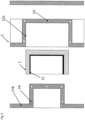
- the Figure 1 shows a sectional view of a tool mold 2 in the closed state, wherein the tool mold 2 is formed by two opposing tool cavities 21a and 21b, wherein the aforementioned opposing tool cavities 21a and 21b enclose a shaping mold cavity 22.
- the first tool cavity 21a is equipped with a plurality of heating channels 24, via which a heating medium can be supplied to the first tool cavity 21a, via which the first tool cavity 21a can be heated to a defined temperature.
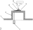
- FIG. 2 an exemplary embodiment of a tool cavity 21 of a tool mold 2 is shown, wherein the tool cavity shown comprises a temperature sensor 4, by means of which the temperature of the tool cavity 21 can be measured.
- the tool cavity shown comprises a temperature sensor 4, by means of which the temperature of the tool cavity 21 can be measured.
- the process of applying the granulate 3 by means of a spray gun 32 is shown, whereby the applied granulate is Area of the tool cavity 21 forms a film layer 31 with a film layer thickness 33.
- the layer thicknesses 33 of the applied granulate 3 can be adjusted or specifically influenced in sections in the tool cavity 21 by targeted application of the granulate 3 using the spray gun 32.
- the Figure 3 shows a plastic molded body with a proportionate film layer coating 11, wherein the foam molded body was applied to the plastic molded body 1 according to the invention using the tool mold 2, which is formed from a first tool cavity 21a and a second opposite tool cavity 21b, over which the plastic molded body was produced, by applying plastic granulate 3 to the second tool cavity 21, the film layer coating 11 was applied to the plastic molded body 1 according to the invention.
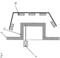
- the Figure 4 shows a further embodiment of a tool cavity 21 with a temperature sensor 4 and an external heat source 55 in the form of several heaters with directional baffles.
- the tool cavity 21 can be heated to a defined temperature by means of the external heat source 55, the sensor 4 can be used to control the heat source 55.
Landscapes
- Engineering & Computer Science (AREA)
- Mechanical Engineering (AREA)
- Processing And Handling Of Plastics And Other Materials For Molding In General (AREA)
- Application Of Or Painting With Fluid Materials (AREA)
- Moulds For Moulding Plastics Or The Like (AREA)
- Molding Of Porous Articles (AREA)
- Moulding By Coating Moulds (AREA)
Applications Claiming Priority (2)
| Application Number | Priority Date | Filing Date | Title |
|---|---|---|---|
| DE102019127756.6A DE102019127756A1 (de) | 2019-10-15 | 2019-10-15 | Verfahren zum Herstellen eines geschäumten Kunststoffformkörpers mit einem Filmschichtüberzug |
| PCT/EP2020/078784 WO2021074153A1 (de) | 2019-10-15 | 2020-10-13 | Verfahren zum herstellen eines geschäumten kunststoffformkörpers mit einem filmschichtüberzug |
Publications (3)
| Publication Number | Publication Date |
|---|---|
| EP4045260A1 EP4045260A1 (de) | 2022-08-24 |
| EP4045260C0 EP4045260C0 (de) | 2024-10-09 |
| EP4045260B1 true EP4045260B1 (de) | 2024-10-09 |
Family
ID=72915814
Family Applications (1)
| Application Number | Title | Priority Date | Filing Date |
|---|---|---|---|
| EP20792957.1A Active EP4045260B1 (de) | 2019-10-15 | 2020-10-13 | Verfahren zum herstellen eines geschäumten kunststoffformkörpers mit einem filmschichtüberzug |
Country Status (9)
| Country | Link |
|---|---|
| US (1) | US20220339828A1 (pl) |
| EP (1) | EP4045260B1 (pl) |
| JP (1) | JP7531586B2 (pl) |
| CN (1) | CN114423579B (pl) |
| DE (1) | DE102019127756A1 (pl) |
| ES (1) | ES3007215T3 (pl) |
| HU (1) | HUE069972T2 (pl) |
| PL (1) | PL4045260T3 (pl) |
| WO (1) | WO2021074153A1 (pl) |
Families Citing this family (1)
| Publication number | Priority date | Publication date | Assignee | Title |
|---|---|---|---|---|
| DE102024128333A1 (de) * | 2024-10-01 | 2026-04-02 | Bayerische Motoren Werke Aktiengesellschaft | Verfahren zur Herstellung einer Energiespeichervorrichtung insbesondere für ein Kraftfahrzeug |
Citations (1)
| Publication number | Priority date | Publication date | Assignee | Title |
|---|---|---|---|---|
| DE10033877A1 (de) * | 2000-07-12 | 2002-03-14 | Fraunhofer Ges Forschung | Verfahren zur Herstellung von Formteilen aus Partikelschaum mit einer Deckschicht |
Family Cites Families (20)
| Publication number | Priority date | Publication date | Assignee | Title |
|---|---|---|---|---|
| IT1202066B (it) * | 1985-05-31 | 1989-02-02 | Piero Cretti | Procedimento per la fabbricazione di elementi in materiale sintetico espanso dotati di strati particolarmente resistenti, impianto per attuare in detto, e prodotti cosi' ottenuti |
| JPS63312248A (ja) * | 1987-06-05 | 1988-12-20 | Arakawa Shatai Kogyo Kk | 車両用内装部品の製造方法 |
| CN1105376A (zh) * | 1992-09-24 | 1995-07-19 | 拉波特股份有限公司 | 涂料组合物 |
| GB2300588B (en) * | 1992-09-24 | 1997-04-30 | Fuller H B Co | Coated Substrates |
| JP3917233B2 (ja) * | 1997-03-05 | 2007-05-23 | しげる工業株式会社 | 車両用内装材およびその製造方法 |
| CN1974169B (zh) * | 2001-02-05 | 2012-02-29 | 3Dm全球有限公司 | 塑料复合制品 |
| DE10158152A1 (de) * | 2001-11-28 | 2003-06-12 | Fagerdala Deutschland Gmbh | Verfahren zur Herstellung von Kunststoffhohlkörpern mit Schaumstofffüllung |
| US20050017391A1 (en) * | 2003-07-22 | 2005-01-27 | Sumitomo Chemical Company, Limited | Method for producing a thermoplastic resin molded article |
| AT500869B1 (de) * | 2004-08-20 | 2007-05-15 | Steiner Peter | Vorrichtung zum herstellen von mit einer folie beschichteten behältern |
| DE102004062510A1 (de) * | 2004-12-24 | 2006-07-06 | Bayer Materialscience Ag | Verfahren zum Formen und Beschichten eines Substrats |
| JP2006247868A (ja) * | 2005-03-08 | 2006-09-21 | Kaneka Corp | 自動車内装材および自動車内装部品 |
| DE102006024940A1 (de) * | 2006-05-29 | 2007-12-20 | Apeg Agrar-Projektentwicklung Gmbh | Verfahren zur Herstellung eines Gegenstandes aus einem Schaumstoff enthaltenden Material und ein solcher Gegenstand |
| GB2460838C (en) * | 2008-06-09 | 2013-11-06 | Nicholas Stillwell | Process for moulding plastic articles |
| GB201115724D0 (en) * | 2011-09-12 | 2011-10-26 | Origin Ltd | Methods of manufacturing plastic articles |
| DE102012015715A1 (de) * | 2012-08-08 | 2014-02-13 | Hans Wobbe | Fertigungsverfahren für ein faserverstärktes Kunststoff-Sandwichbauteil mit multifunktionalen Hybridschäumen |
| EP3107704B1 (de) * | 2014-02-19 | 2021-03-24 | Shanghai Yanfeng Jinqiao Automotive Trim Systems Co., Ltd. | Mehrschichtiger formkörper für fahrzeuginnenausstattungen sowie verfahren zur herstellung solcher formkörper |
| WO2015124660A1 (de) * | 2014-02-19 | 2015-08-27 | Johnson Controls Interiors Gmbh & Co. Kg | Mehrschichtiger formkörper für fahrzeuginnenausstattungen sowie verfahren zur herstellung solcher formkörper |
| DE102014222958A1 (de) * | 2014-11-11 | 2016-05-12 | Benecke-Kaliko Aktiengesellschaft | Verfahren zur Herstellung eines Schaumfolienlaminats und dessen Verwendung |
| JP6511788B2 (ja) * | 2014-12-05 | 2019-05-15 | 株式会社ジェイエスピー | 表皮材付発泡成形体及びその製造方法 |
| AT518100A1 (de) * | 2015-12-22 | 2017-07-15 | Fill Gmbh | Verfahren zur Herstellung eines Formkörpers aus einem Partikelschaummaterial |
-
2019
- 2019-10-15 DE DE102019127756.6A patent/DE102019127756A1/de not_active Ceased
-
2020
- 2020-10-13 ES ES20792957T patent/ES3007215T3/es active Active
- 2020-10-13 EP EP20792957.1A patent/EP4045260B1/de active Active
- 2020-10-13 US US17/764,306 patent/US20220339828A1/en active Pending
- 2020-10-13 JP JP2022521764A patent/JP7531586B2/ja active Active
- 2020-10-13 PL PL20792957.1T patent/PL4045260T3/pl unknown
- 2020-10-13 HU HUE20792957A patent/HUE069972T2/hu unknown
- 2020-10-13 WO PCT/EP2020/078784 patent/WO2021074153A1/de not_active Ceased
- 2020-10-13 CN CN202080066031.0A patent/CN114423579B/zh active Active
Patent Citations (1)
| Publication number | Priority date | Publication date | Assignee | Title |
|---|---|---|---|---|
| DE10033877A1 (de) * | 2000-07-12 | 2002-03-14 | Fraunhofer Ges Forschung | Verfahren zur Herstellung von Formteilen aus Partikelschaum mit einer Deckschicht |
Also Published As
| Publication number | Publication date |
|---|---|
| CN114423579B (zh) | 2025-03-28 |
| EP4045260A1 (de) | 2022-08-24 |
| PL4045260T3 (pl) | 2025-06-02 |
| US20220339828A1 (en) | 2022-10-27 |
| JP7531586B2 (ja) | 2024-08-09 |
| JP2022553919A (ja) | 2022-12-27 |
| BR112022004888A2 (pt) | 2022-07-19 |
| EP4045260C0 (de) | 2024-10-09 |
| CN114423579A (zh) | 2022-04-29 |
| ES3007215T3 (en) | 2025-03-19 |
| DE102019127756A1 (de) | 2021-04-15 |
| WO2021074153A1 (de) | 2021-04-22 |
| HUE069972T2 (hu) | 2025-04-28 |
Similar Documents
| Publication | Publication Date | Title |
|---|---|---|
| DE10331657A1 (de) | Verfahren zur Herstellung eines Formteiles aus geschäumtem Kunststof und Formteil aus geschäumtem Kunststoff | |
| DE102016223980A1 (de) | Verfahren zur Herstellung eines Kunststoffformteils, Kunststoffformteil und Schuh | |
| EP3393743A1 (de) | Verfahren zur herstellung eines formkörpers aus einem partikelschaummaterial | |
| DE69113535T2 (de) | Metallform mit vergrösserter Oberfläche zur Wärmeübertragung. | |
| EP1592554B1 (de) | Schaumstoffkörper, insbesondere ausstattungsteil für den innenraum eines kraftfahrzeugs, und verfahren zu seiner herstellung | |
| WO2002004188A1 (de) | Verfahren zur herstellung von formteilen aus partikelschaum mit einer deckschicht | |
| DE4406039C1 (de) | Formkörper aus Verbundmaterial und Verfahren zur Herstellung eines solchen Verbundmaterials | |
| EP0923442B1 (de) | Verfahren zur herstellung von verbundkörpern aus kunststoff | |
| DE102020106725A1 (de) | Verfahren und Werkzeug zur Herstellung eines Partikelschaum-Formteils | |
| EP2540471A2 (de) | Verfahren zur Herstellung von Formteilen und Formteil | |
| DE4443145C1 (de) | Verfahren und Vorrichtung zur Beschichtung warm verformter thermoplastischer Bauteile mit thermoplastischen Oberflächenmaterialien | |
| WO2021009720A2 (de) | Verfahren zur herstellung von formteilen aus partikelschäumen | |
| DE102019127756A1 (de) | Verfahren zum Herstellen eines geschäumten Kunststoffformkörpers mit einem Filmschichtüberzug | |
| DE102005029177A1 (de) | Fahrzeugteil mit integrierter Stossaufnahmeeinrichtung sowie Verfahren zum Herstellen desselben | |
| WO2008113615A2 (de) | Verfahren und vorrichtung zur herstellung von formhäuten aus mehreren kunststoffen | |
| DE102014112890A1 (de) | Vorrichtung und Verfahren zur Herstellung einer Verzierung für ein Fahrzeug | |
| EP2136982B1 (de) | Form und verfahren zur herstellung von formhäuten und formkörpern aus kunststoff | |
| DE102004031414B4 (de) | Verfahren zur Herstellung eines Innenausstattungssystems | |
| DE19744165C2 (de) | Werkzeug zum Herstellen eines Partikelschaumstoff-Formkörpers und Verfahren zur Herstellung eines solchen Werkzeuges | |
| DE10311667A1 (de) | Verfahren zum Hinterschäumen von Slushschichten | |
| DE102014208835A1 (de) | Verfahren zur Herstellung eines Kunststoffbauteils | |
| DE102022105108A1 (de) | Leichtbauteil und Verfahren zur Herstellung eines Leichtbauteils | |
| EP2576173B1 (de) | Verfahren zum erzeugen einer formhaut mit einem dekor, verfahren zur herstellung eines fahrzeuginnenverkleidungsteils | |
| DE102016207283A1 (de) | Verfahren und System zum additiven Erzeugen eines Bauteils | |
| DE10348262B4 (de) | Verfahren zum Herstellen einer Oberflächenbeschichtung |
Legal Events
| Date | Code | Title | Description |
|---|---|---|---|
| STAA | Information on the status of an ep patent application or granted ep patent |
Free format text: STATUS: UNKNOWN |
|
| STAA | Information on the status of an ep patent application or granted ep patent |
Free format text: STATUS: THE INTERNATIONAL PUBLICATION HAS BEEN MADE |
|
| PUAI | Public reference made under article 153(3) epc to a published international application that has entered the european phase |
Free format text: ORIGINAL CODE: 0009012 |
|
| STAA | Information on the status of an ep patent application or granted ep patent |
Free format text: STATUS: REQUEST FOR EXAMINATION WAS MADE |
|
| 17P | Request for examination filed |
Effective date: 20220330 |
|
| AK | Designated contracting states |
Kind code of ref document: A1 Designated state(s): AL AT BE BG CH CY CZ DE DK EE ES FI FR GB GR HR HU IE IS IT LI LT LU LV MC MK MT NL NO PL PT RO RS SE SI SK SM TR |
|
| DAV | Request for validation of the european patent (deleted) | ||
| DAX | Request for extension of the european patent (deleted) | ||
| STAA | Information on the status of an ep patent application or granted ep patent |
Free format text: STATUS: EXAMINATION IS IN PROGRESS |
|
| 17Q | First examination report despatched |
Effective date: 20231030 |
|
| GRAP | Despatch of communication of intention to grant a patent |
Free format text: ORIGINAL CODE: EPIDOSNIGR1 |
|
| STAA | Information on the status of an ep patent application or granted ep patent |
Free format text: STATUS: GRANT OF PATENT IS INTENDED |
|
| INTG | Intention to grant announced |
Effective date: 20240502 |
|
| GRAS | Grant fee paid |
Free format text: ORIGINAL CODE: EPIDOSNIGR3 |
|
| GRAA | (expected) grant |
Free format text: ORIGINAL CODE: 0009210 |
|
| STAA | Information on the status of an ep patent application or granted ep patent |
Free format text: STATUS: THE PATENT HAS BEEN GRANTED |
|
| AK | Designated contracting states |
Kind code of ref document: B1 Designated state(s): AL AT BE BG CH CY CZ DE DK EE ES FI FR GB GR HR HU IE IS IT LI LT LU LV MC MK MT NL NO PL PT RO RS SE SI SK SM TR |
|
| REG | Reference to a national code |
Ref country code: CH Ref legal event code: EP |
|
| REG | Reference to a national code |
Ref country code: DE Ref legal event code: R096 Ref document number: 502020009463 Country of ref document: DE |
|
| REG | Reference to a national code |
Ref country code: IE Ref legal event code: FG4D Free format text: LANGUAGE OF EP DOCUMENT: GERMAN |
|
| U01 | Request for unitary effect filed |
Effective date: 20241108 |
|
| U07 | Unitary effect registered |
Designated state(s): AT BE BG DE DK EE FI FR IT LT LU LV MT NL PT RO SE SI Effective date: 20241119 |
|
| U20 | Renewal fee for the european patent with unitary effect paid |
Year of fee payment: 5 Effective date: 20250116 |
|
| REG | Reference to a national code |
Ref country code: SK Ref legal event code: T3 Ref document number: E 45834 Country of ref document: SK |
|
| REG | Reference to a national code |
Ref country code: ES Ref legal event code: FG2A Ref document number: 3007215 Country of ref document: ES Kind code of ref document: T3 Effective date: 20250319 |
|
| PG25 | Lapsed in a contracting state [announced via postgrant information from national office to epo] |
Ref country code: HR Free format text: LAPSE BECAUSE OF FAILURE TO SUBMIT A TRANSLATION OF THE DESCRIPTION OR TO PAY THE FEE WITHIN THE PRESCRIBED TIME-LIMIT Effective date: 20241009 Ref country code: IS Free format text: LAPSE BECAUSE OF FAILURE TO SUBMIT A TRANSLATION OF THE DESCRIPTION OR TO PAY THE FEE WITHIN THE PRESCRIBED TIME-LIMIT Effective date: 20250209 |
|
| PG25 | Lapsed in a contracting state [announced via postgrant information from national office to epo] |
Ref country code: NO Free format text: LAPSE BECAUSE OF FAILURE TO SUBMIT A TRANSLATION OF THE DESCRIPTION OR TO PAY THE FEE WITHIN THE PRESCRIBED TIME-LIMIT Effective date: 20250109 |
|
| PG25 | Lapsed in a contracting state [announced via postgrant information from national office to epo] |
Ref country code: GR Free format text: LAPSE BECAUSE OF FAILURE TO SUBMIT A TRANSLATION OF THE DESCRIPTION OR TO PAY THE FEE WITHIN THE PRESCRIBED TIME-LIMIT Effective date: 20250110 |
|
| REG | Reference to a national code |
Ref country code: HU Ref legal event code: AG4A Ref document number: E069972 Country of ref document: HU |
|
| PG25 | Lapsed in a contracting state [announced via postgrant information from national office to epo] |
Ref country code: RS Free format text: LAPSE BECAUSE OF FAILURE TO SUBMIT A TRANSLATION OF THE DESCRIPTION OR TO PAY THE FEE WITHIN THE PRESCRIBED TIME-LIMIT Effective date: 20250109 |
|
| REG | Reference to a national code |
Ref country code: CH Ref legal event code: PL |
|
| PG25 | Lapsed in a contracting state [announced via postgrant information from national office to epo] |
Ref country code: SM Free format text: LAPSE BECAUSE OF FAILURE TO SUBMIT A TRANSLATION OF THE DESCRIPTION OR TO PAY THE FEE WITHIN THE PRESCRIBED TIME-LIMIT Effective date: 20241009 |
|
| PG25 | Lapsed in a contracting state [announced via postgrant information from national office to epo] |
Ref country code: MC Free format text: LAPSE BECAUSE OF FAILURE TO SUBMIT A TRANSLATION OF THE DESCRIPTION OR TO PAY THE FEE WITHIN THE PRESCRIBED TIME-LIMIT Effective date: 20241009 |
|
| PG25 | Lapsed in a contracting state [announced via postgrant information from national office to epo] |
Ref country code: CH Free format text: LAPSE BECAUSE OF NON-PAYMENT OF DUE FEES Effective date: 20241031 |
|
| PLBE | No opposition filed within time limit |
Free format text: ORIGINAL CODE: 0009261 |
|
| STAA | Information on the status of an ep patent application or granted ep patent |
Free format text: STATUS: NO OPPOSITION FILED WITHIN TIME LIMIT |
|
| 26N | No opposition filed |
Effective date: 20250710 |
|
| PG25 | Lapsed in a contracting state [announced via postgrant information from national office to epo] |
Ref country code: IE Free format text: LAPSE BECAUSE OF NON-PAYMENT OF DUE FEES Effective date: 20241013 |
|
| U21 | Renewal fee for the european patent with unitary effect paid with additional fee |
Year of fee payment: 6 Effective date: 20251121 |
|
| PGFP | Annual fee paid to national office [announced via postgrant information from national office to epo] |
Ref country code: GB Payment date: 20251127 Year of fee payment: 6 |
|
| PGFP | Annual fee paid to national office [announced via postgrant information from national office to epo] |
Ref country code: HU Payment date: 20251208 Year of fee payment: 6 |
|
| PGFP | Annual fee paid to national office [announced via postgrant information from national office to epo] |
Ref country code: CZ Payment date: 20251128 Year of fee payment: 6 |
|
| PGFP | Annual fee paid to national office [announced via postgrant information from national office to epo] |
Ref country code: PL Payment date: 20251203 Year of fee payment: 6 |
|
| PGFP | Annual fee paid to national office [announced via postgrant information from national office to epo] |
Ref country code: SK Payment date: 20251209 Year of fee payment: 6 |
|
| PG25 | Lapsed in a contracting state [announced via postgrant information from national office to epo] |
Ref country code: CY Free format text: LAPSE BECAUSE OF FAILURE TO SUBMIT A TRANSLATION OF THE DESCRIPTION OR TO PAY THE FEE WITHIN THE PRESCRIBED TIME-LIMIT; INVALID AB INITIO Effective date: 20201013 |
|
| PGFP | Annual fee paid to national office [announced via postgrant information from national office to epo] |
Ref country code: ES Payment date: 20251121 Year of fee payment: 6 |