EP4043749B1 - Codierte steckbare wellenkupplung - Google Patents
Codierte steckbare wellenkupplung Download PDFInfo
- Publication number
- EP4043749B1 EP4043749B1 EP21166611.0A EP21166611A EP4043749B1 EP 4043749 B1 EP4043749 B1 EP 4043749B1 EP 21166611 A EP21166611 A EP 21166611A EP 4043749 B1 EP4043749 B1 EP 4043749B1
- Authority
- EP
- European Patent Office
- Prior art keywords
- coupling
- intermediate element
- shaft
- recesses
- coupling elements
- Prior art date
- Legal status (The legal status is an assumption and is not a legal conclusion. Google has not performed a legal analysis and makes no representation as to the accuracy of the status listed.)
- Active
Links
Images


Classifications
-
- F—MECHANICAL ENGINEERING; LIGHTING; HEATING; WEAPONS; BLASTING
- F16—ENGINEERING ELEMENTS AND UNITS; GENERAL MEASURES FOR PRODUCING AND MAINTAINING EFFECTIVE FUNCTIONING OF MACHINES OR INSTALLATIONS; THERMAL INSULATION IN GENERAL
- F16D—COUPLINGS FOR TRANSMITTING ROTATION; CLUTCHES; BRAKES
- F16D3/00—Yielding couplings, i.e. with means permitting movement between the connected parts during the drive
- F16D3/50—Yielding couplings, i.e. with means permitting movement between the connected parts during the drive with the coupling parts connected by one or more intermediate members
- F16D3/72—Yielding couplings, i.e. with means permitting movement between the connected parts during the drive with the coupling parts connected by one or more intermediate members with axially-spaced attachments to the coupling parts
-
- F—MECHANICAL ENGINEERING; LIGHTING; HEATING; WEAPONS; BLASTING
- F16—ENGINEERING ELEMENTS AND UNITS; GENERAL MEASURES FOR PRODUCING AND MAINTAINING EFFECTIVE FUNCTIONING OF MACHINES OR INSTALLATIONS; THERMAL INSULATION IN GENERAL
- F16D—COUPLINGS FOR TRANSMITTING ROTATION; CLUTCHES; BRAKES
- F16D3/00—Yielding couplings, i.e. with means permitting movement between the connected parts during the drive
- F16D3/02—Yielding couplings, i.e. with means permitting movement between the connected parts during the drive adapted to specific functions
- F16D3/04—Yielding couplings, i.e. with means permitting movement between the connected parts during the drive adapted to specific functions specially adapted to allow radial displacement, e.g. Oldham couplings
-
- F—MECHANICAL ENGINEERING; LIGHTING; HEATING; WEAPONS; BLASTING
- F16—ENGINEERING ELEMENTS AND UNITS; GENERAL MEASURES FOR PRODUCING AND MAINTAINING EFFECTIVE FUNCTIONING OF MACHINES OR INSTALLATIONS; THERMAL INSULATION IN GENERAL
- F16D—COUPLINGS FOR TRANSMITTING ROTATION; CLUTCHES; BRAKES
- F16D3/00—Yielding couplings, i.e. with means permitting movement between the connected parts during the drive
- F16D3/02—Yielding couplings, i.e. with means permitting movement between the connected parts during the drive adapted to specific functions
- F16D3/06—Yielding couplings, i.e. with means permitting movement between the connected parts during the drive adapted to specific functions specially adapted to allow axial displacement
-
- F—MECHANICAL ENGINEERING; LIGHTING; HEATING; WEAPONS; BLASTING
- F16—ENGINEERING ELEMENTS AND UNITS; GENERAL MEASURES FOR PRODUCING AND MAINTAINING EFFECTIVE FUNCTIONING OF MACHINES OR INSTALLATIONS; THERMAL INSULATION IN GENERAL
- F16D—COUPLINGS FOR TRANSMITTING ROTATION; CLUTCHES; BRAKES
- F16D3/00—Yielding couplings, i.e. with means permitting movement between the connected parts during the drive
- F16D3/50—Yielding couplings, i.e. with means permitting movement between the connected parts during the drive with the coupling parts connected by one or more intermediate members
- F16D3/70—Yielding couplings, i.e. with means permitting movement between the connected parts during the drive with the coupling parts connected by one or more intermediate members comprising elastic elements arranged in holes in one coupling part and surrounding pins on the other coupling part
-
- H—ELECTRICITY
- H02—GENERATION; CONVERSION OR DISTRIBUTION OF ELECTRIC POWER
- H02K—DYNAMO-ELECTRIC MACHINES
- H02K11/00—Structural association of dynamo-electric machines with electric components or with devices for shielding, monitoring or protection
- H02K11/20—Structural association of dynamo-electric machines with electric components or with devices for shielding, monitoring or protection for measuring, monitoring, testing, protecting or switching
- H02K11/21—Devices for sensing speed or position, or actuated thereby
Definitions
- the present invention relates to a coded plug-in shaft coupling according to the preamble of claim 1.
- Embodiments of the present invention are particularly relevant in the field of servo motors. These types of motors are operated together with an encoder, whereby the encoder detects the current angular position of the motor shaft and feeds this information to a control loop which in turn controls the current supply to the motor windings of the servo motor.
- the encoder shaft is connected to the motor shaft via a shaft coupling.
- a measuring scale is mounted on the encoder shaft to determine the angular position of the motor shaft.
- An important task of the encoder is to determine the commutation between the rotor and stator so that the motor windings are properly energized. The commutation angle is determined once after the encoder has been mounted on the motor with the aid of the encoder and stored permanently.
- the information of the commutation angle is lost when the encoder is disassembled and reassembled. This is the case, for example, if a defective motor or encoder has to be replaced. In this case, the commutation has to be set again, which can be very time-consuming depending on the application.
- the utility model DE 20 2008 010 765 U1 proposes a design of a plug-in coupling according to the preamble of claim 1.
- this coupling allows for joining the two shafts in different angular positions.
- the commutation has to be set again after a replacement the motor or the encoder.
- EP 2 189 675 B1 also describes a design of a plug-in coupling according to the preamble of claim 1.
- the two shafts can be joined in different angular positions.
- a further disadvantage of this solution is the joining of the couplings which requires significant attention and care, since the design distinction of the rotation angle position is not very pronounced and does not include elements for simplified joining.
- EP 2 711 497 A1 discloses a coded plug-in shaft coupling with the features of the preamble of claim 1.
- US 1 887 081 A discloses a coded plug-in shaft coupling according to the preamble of claim 1.
- the present invention provides a coded plug-in shaft coupling, comprising
- Angle coding is provided by coding means in form of at least one coding recess arranged at each of the first and the second coupling elements and at least one coding extension arranged at each side of the intermediate element matching the coding recess of each of the coupling element.
- coding recesses Preferably there are two coding recesses and two coding extensions for balance reasons.
- the two coding recesses are different in shape and in their positions at the coupling element and match the shape and positions of the two coding extensions at the intermediate element.
- the intermediate element and the two coupling elements comprise coupling means.
- the intermediate element has a plurality of connecting claws at each side extending parallel to the axis of rotation.
- the connecting claws are formed to match and engage a plurality of coupling recesses provided at each of the coupling elements.
- a further advantage of the present invention is the relatively simple assembly, since the intermediate element and the two coupling elements preferably have means for an easier connection, preferably in form of insertion slopes at the coupling means.
- the shaft coupling system is backlash-free in the joined state.
- each of the coupling elements and the intermedia element is balanced in the direction of rotation. Particular care was taken to ensure that the design features for angle encoding are well balanced along the axis of rotation.
- the intermediate element can be provided with a reinforced outer ring, which increases torsional stiffness and improves torque transmission.
- the means for encoding the angular position are formed by the connecting claws and coupling recesses themselves, in that at least one connecting claw and coupling recess have a different shape than the other connecting claws and coupling recesses and in this way only one position for the coupling between the coupling elements and the intermedia element is possible.
- the coded plug-in shaft coupling according to the invention is provided for use together with a rotary encoder, in particular for use together with a rotary encoder mounted in an assembly which is part of a servo motor.
- the coupling is particularly suited for field replaceability of the motor or the encoder of the servo motor assembly without losing the correlation between the angular position of the encoder and the angular position of the motor.
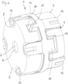
- Embodiments of the present invention relate to a new type of plug-in and coded shaft coupling for connecting two end shafts mounted rotatably on bearings.
- the shaft coupling 1 consists of a first coupling element 2 and a second coupling element 3 which are to be coupled together by means of an intermediate element 10.
- the first coupling element 2 is to be fixedly connected to an end of a first shaft (not shown) by means of its hub 4 and by way of fitting surfaces 6, and the second coupling element 3 is to be fixedly connected to an end of a second shaft (not shown) by means of its hub 5 and by way of fitting surfaces 7.
- the first and second shafts are generally arranged in alignment with one another and connected to the hubs 4, 5 of the coupling elements 2, 3 for example by press-fit, connection screws, adhesive joint or other known connection methods.
- both coupling elements 2, 3 are designed in the shape of a ring disc and preferably have a plurality of semicircular coupling recesses 8, 9 at a radial distance from the rotational axis, preferably in the region of the outer peripheral surface.
- the semicircular coupling recesses 8, 9 can preferably be arranged at equal angular intervals on the outer circumferential surface of the coupling elements 2, 3.
- the intermediate element 10 is arranged between the first and second coupling elements 2 , 3 and connects the coupling elements 2, 3 to one another in a rotationally fixed manner.
- a plurality of connecting claws 12, 13 are disposed on both sides of the intermediate element 10 and arranged at a distance from the rotational axis and adjacent to the outer circumferential surface.
- the connecting claws 12, 13 extending from both sides of the intermediate element 10 at a predetermined distance from the axis of rotation and parallel thereto.
- the connecting claws 12, 13 extending in opposite directions to each other and are arranged offset at a predetermined angle to one another on the periphery of the rotary body 11 of the intermediate element 10.
- the connecting claws 12, 13 preferably have a semi-cylindrical shape which is formed to match the semicircular coupling recesses 8, 9 of the coupling elements 2, 3.
- the connecting claws 12 of the intermediate element 10 positively engage in the coupling recesses 8 of the first coupling element 2.
- the connecting claws 13 of the intermediate element 10 positively engage in the coupling recesses 9 of the second coupling element 3.
- the connecting claws 12, 13 have force-transmitting surfaces 15 which preferably have a half-cylindrical or a curved shape.
- the coupling recesses 8, 9 have force-transmitting surfaces 14 which are of bulbous or curved design.
- the force-transmitting surfaces 14, 15 ensure an advantageously angularly movable positive-locking connection between the connecting claws 12 ,13 of the intermediate element 10 and the coupling recesses 8, 9 of the coupling elements 2, 3.
- the coupling recesses 8, 9 of the coupling elements 2, 3 and / or the connecting claws 12, 13 of the intermediate element 10 have beveled edges that form insertion slopes for easier plugging together the coupling elements 2, 3 and the intermediate element 10.
- the coupling elements 2, 3 each have two coding recesses 16, 17 in addition to the coupling recesses 8.
- the coding recesses 16, 17 are located at a distance from each other and are differently shaped and are arranged at different positions on the coupling elements 2, 3.
- the intermediate element 10 has two coding extensions 18, 19 on each side, which also have different shapes and positions and match the shape and positions of the coding recesses 16, 17 of the coupling elements 2, 3.
- a first coding extension 18 of the intermediate element 10 in formed to engage a first coding recess 16 of the coupling elements 2, 3, and a second coding extension 19 of the intermediate element 10 is formed to engage a second coding recess 17 of the coupling elements 2, 3.
- the intermediate element 110 can be provided with a reinforced outer ring 112, which surrounds the rotational body 111, increases torsional stiffness and improves torque transmission between the intermediate element 110 and the coupling elements 2, 3.
- Fig. 6 shows the shaft coupling with the coupling elements 2, 3 joined with the intermediate element 10.
- the connecting claws 12, 13 of the intermediate element 10 engage the coupling recesses 8, 9 of the coupling elements 2, 3.
- Each coding extension 18, 19 engages its corresponding coding recess 16, 17. Due to the different shapes of the coding recesses 16, 17 of the coupling elements 2, 3 and the corresponding coding extensions 18, 19 at the intermediate element 10, both coupling elements 2, 3 can only be coupled in one defined angular position with the intermediate element 10.
Landscapes
- Engineering & Computer Science (AREA)
- General Engineering & Computer Science (AREA)
- Mechanical Engineering (AREA)
- Microelectronics & Electronic Packaging (AREA)
- Power Engineering (AREA)
- Transmission And Conversion Of Sensor Element Output (AREA)
- Mutual Connection Of Rods And Tubes (AREA)
Claims (12)
- Codierte Steckwellenkupplung, umfassend:ein erstes Kopplungselement (2),ein zweites Kopplungselement (3),ein Zwischenelement (10), das einen axialen, radialen und Winkel-Fluchtungsfehler zwischen zwei Wellen ausgleicht,ein Kopplungsmittel für eine mechanische und torsionssteife Verbindung des Zwischenelements (10) und des ersten und des zweiten Kopplungselements (2, 3), wobei das Kopplungsmittel eine Mehrzahl von Kopplungsausnehmungen (8, 9) umfasst, die an dem ersten und dem zweiten Kopplungselement (2, 3) vorgesehen sind, wobei die Ausnehmungen (8, 9) in einem radialen Abstand von einer Drehachse der Kopplungselemente (8, 9) angeordnet sind,wobei das Kopplungsmittel ferner eine Mehrzahl von Verbindungsklauen (12, 13) umfasst, die an dem Zwischenelement (10, 110) vorgesehen sind, wobei sich die Verbindungsklauen (12, 13) von beiden Seiten des Zwischenelements (10) aus parallel zu und in einem radialen Abstand von der Drehachse erstrecken und so ausgebildet sind, dass sie mit der Mehrzahl der Kopplungsausnehmungen (8, 9), die jeweils an den Kopplungselementen (2, 3) vorgesehen sind, zusammenpassen und mit ihnen in Eingriff kommen,dadurch gekennzeichnet, dass das erste und das zweite Kopplungselement (2, 3) und das Zwischenelement (10, 110) in einer solchen Weise ausgebildet sind, dass die ersten Kopplungselemente (2, 3) nur in einer vorbestimmten Winkelposition zu verbinden sind, wobei das erste und das zweite Kopplungselement (2, 3) zur Winkelpositionierung jeweils mindestens zwei Codierungsausnehmungen (16, 17) aufweisen, die in einem Abstand voneinander angeordnet sind und unterschiedlich geformt sind und an unterschiedlichen Positionen auf den Kopplungselementen (2, 3) angeordnet sind, und das Zwischenelement (10, 110) zur Winkelpositionierung mindestens zwei Codierungsvorsprünge (18, 19) auf jeder Seite hat, die in Form und Position mit den Codierungsausnehmungen (16, 17) der Kopplungselemente (2, 3) zusammenpassen.
- Codierte Steckwellenkupplung gemäß Anspruch 1, dadurch gekennzeichnet, dass das erste und das zweite Kopplungselement (2, 3) jeweils mindestens zwei Codierungsausnehmungen (16, 17) aufweisen, die unterschiedliche Formen und Positionen haben, und dass das Zwischenelement (10, 110) auf jeder Seite mindestens zwei Codierungsfortsätze (18, 19) hat, die unterschiedliche Formen und Positionen haben und zur Winkelpositionierung mit den Formen und Positionen der mindestens zwei Codierungsausnehmungen (16, 17) der Kopplungselemente (2, 3) zusammenpassen.
- Codierte Steckwellenkupplung gemäß Anspruch 1, dadurch gekennzeichnet, dass die Kopplungsausnehmungen (8, 9) der Kopplungselemente (2, 3) eine halbkreisförmige oder gekrümmte Form haben.
- Codierte Steckwellenkupplung gemäß Anspruch 1, dadurch gekennzeichnet, dass sich die Verbindungsklauen (12, 13) an beiden Seiten des Zwischenelements (10, 110) in entgegengesetzten Richtungen zueinander erstrecken und auf dem Umfang eines Rotationskörpers (11, 111) des Zwischenelements (10, 110) in einem bestimmten Winkel zueinander versetzt angeordnet sind.
- Codierte Steckwellenkupplung gemäß Anspruch 1, dadurch gekennzeichnet, dass die Verbindungsklauen (12, 13) des Zwischenelements (10, 110) kraftübertragende Oberflächen (14) haben, die eine halbkreisförmige oder gekrümmte Form haben.
- Codierte Steckwellenkupplung gemäß einem der Ansprüche 1 bis 5, dadurch gekennzeichnet, dass die Kopplungsausnehmungen (8, 9) der Kopplungselemente (2, 3) und/oder der Verbindungsklauen (12, 13) des Zwischenelements (10, 110) angeschrägte Kanten haben, die Einführschrägen ausbilden.
- Codierte Steckwellenkupplung gemäß einem der Ansprüche 1 bis 6, dadurch gekennzeichnet, dass das Zwischenelement (110) einen verstärkten Außenring (112) umfasst, der den Rotationskörper (111) umgibt.
- Codierte Steckwellenkupplung gemäß einem der Ansprüche 1 bis 7, dadurch gekennzeichnet, dass die Kupplung dazu konstruiert ist, zusammen mit einem Drehgeber verwendet zu werden.
- Codierte Steckwellenkupplung gemäß einem der Ansprüche 1 bis 8, dadurch gekennzeichnet, dass die Kupplung dazu konstruiert ist, zusammen mit einem Drehgeber verwendet zu werden, der in einer Anordnung montiert ist, die Teil eines Stellmotors ist.
- Codierte Steckwellenkupplung gemäß einem der Ansprüche 1 bis 9, dadurch gekennzeichnet, dass die Kupplung dazu konstruiert ist, zusammen mit einem Drehgeber verwendet zu werden, der in einer Anordnung montiert ist, die Teil eines Stellmotors ist und die zur Vor-Ort-Austauschbarkeit geeignet ist.
- Codierte Steckwellenkupplung gemäß einem der Ansprüche 9 oder 10, dadurch gekennzeichnet, dass die Kupplung für einen Austausch des Motors oder des Gebers der Stellmotoranordnung konstruiert ist, ohne dass dabei die Korrelation zwischen der Winkelposition des Gebers und der Winkelposition des Motors verloren geht.
- Stellmotor, der zusammen mit einem Drehgeber betrieben wird, wobei der Drehgeber ein Welle umfasst, die über die codierte Steckwellenkupplung (1) gemäß einem der Ansprüche 1 bis 11 mit einer Welle des Stellmotors verbunden ist, wobei der Drehgeber dazu konstruiert ist, die aktuelle Winkelposition der Motorwelle zu erfassen und diese Information in eine Regelschleife einzuspeisen, die ihrerseits eine Stromversorgung der Motorwicklungen des Stellmotors regelt, wobei die codierte Steckwellenkupplung (1) eine Winkelcodierung bereitstellt, was bedeutet, dass mittels der Steckwellenkupplung (1) die Motorwelle und die Geberwelle nur in einer vordefinierten Winkelposition zusammengefügt werden können, wodurch ein leichter Austausch des Motors oder des Gebers ermöglicht wird, ohne dass dabei die Korrelation zwischen der Winkelposition des Gebers und der Winkelposition des Motors verloren geht.
Priority Applications (1)
| Application Number | Priority Date | Filing Date | Title |
|---|---|---|---|
| CN202210119118.0A CN114941663B (zh) | 2021-02-16 | 2022-02-08 | 编码插入式联轴器 |
Applications Claiming Priority (1)
| Application Number | Priority Date | Filing Date | Title |
|---|---|---|---|
| US202163149937P | 2021-02-16 | 2021-02-16 |
Publications (2)
| Publication Number | Publication Date |
|---|---|
| EP4043749A1 EP4043749A1 (de) | 2022-08-17 |
| EP4043749B1 true EP4043749B1 (de) | 2025-06-04 |
Family
ID=75362442
Family Applications (1)
| Application Number | Title | Priority Date | Filing Date |
|---|---|---|---|
| EP21166611.0A Active EP4043749B1 (de) | 2021-02-16 | 2021-04-01 | Codierte steckbare wellenkupplung |
Country Status (2)
| Country | Link |
|---|---|
| EP (1) | EP4043749B1 (de) |
| CN (1) | CN114941663B (de) |
Families Citing this family (1)
| Publication number | Priority date | Publication date | Assignee | Title |
|---|---|---|---|---|
| CN108361293B (zh) * | 2018-04-24 | 2023-08-22 | 桂林星辰科技股份有限公司 | 一种编码器专用的联轴器 |
Citations (1)
| Publication number | Priority date | Publication date | Assignee | Title |
|---|---|---|---|---|
| US1887081A (en) * | 1932-01-02 | 1932-11-08 | Dodge Mfg Corp | Coupling |
Family Cites Families (10)
| Publication number | Priority date | Publication date | Assignee | Title |
|---|---|---|---|---|
| US1378091A (en) * | 1920-04-12 | 1921-05-17 | Einar F Carlsen | Shaft-coupling |
| US6183368B1 (en) * | 1997-10-09 | 2001-02-06 | Ntn Corporation | One-way over-running flex coupling |
| EP0940594A1 (de) * | 1998-03-02 | 1999-09-08 | ASA Electronic Industry Co., Ltd. | Exzenterwellenkupplung |
| US6440000B1 (en) * | 1999-12-06 | 2002-08-27 | Asa Electronic Industry Co., Ltd. | Universal joint |
| DE202008010765U1 (de) | 2008-08-13 | 2008-10-30 | Ktr Kupplungstechnik Gmbh | Wellenkupplung |
| EP2189675B1 (de) | 2008-11-25 | 2012-05-02 | Siemens Aktiengesellschaft | Wellenkupplung |
| DE102010054510B4 (de) * | 2010-12-15 | 2012-07-12 | Sick Stegmann Gmbh | Wellenkupplung |
| EP2711497B1 (de) * | 2012-09-20 | 2014-08-13 | SIR MECCANICA S.p.A. | Modularschaft für Maschinenwerkzeuge |
| CN105179502A (zh) * | 2015-09-15 | 2015-12-23 | 宁波龙旋机械制造有限公司 | 一种绝缘联轴器及其更换方法 |
| CN108087438A (zh) * | 2017-12-12 | 2018-05-29 | 深圳市英斯玛特科技有限公司 | 电动牙刷刷头及用于连接刷头和动力输出轴的连轴器 |
-
2021
- 2021-04-01 EP EP21166611.0A patent/EP4043749B1/de active Active
-
2022
- 2022-02-08 CN CN202210119118.0A patent/CN114941663B/zh active Active
Patent Citations (1)
| Publication number | Priority date | Publication date | Assignee | Title |
|---|---|---|---|---|
| US1887081A (en) * | 1932-01-02 | 1932-11-08 | Dodge Mfg Corp | Coupling |
Also Published As
| Publication number | Publication date |
|---|---|
| CN114941663B (zh) | 2025-04-04 |
| EP4043749A1 (de) | 2022-08-17 |
| CN114941663A (zh) | 2022-08-26 |
Similar Documents
| Publication | Publication Date | Title |
|---|---|---|
| US7960883B2 (en) | Motor assembly with coaxial shafts | |
| EP2514986B1 (de) | Drehanordnung | |
| US20090230825A1 (en) | Shaft Coupling | |
| US9863480B2 (en) | Wobble mechanism | |
| EP4043749B1 (de) | Codierte steckbare wellenkupplung | |
| EP2726251B1 (de) | Elektrowerkzeug | |
| KR20110136756A (ko) | 소형 전기 모터 | |
| KR20190059847A (ko) | 서보 및 그를 갖는 로봇 | |
| CN1115508A (zh) | 永久磁铁转子 | |
| US6777843B2 (en) | Resolver integrated type motor | |
| EP1314904B1 (de) | Verfahren zum Befestigen einer Hülse auf einer Welle und Hülsenvorrichtung für solch eine Befestigung | |
| JP2013121839A (ja) | 電動パワーステアリング装置 | |
| JP2514505Y2 (ja) | 中空軸形レゾルバ | |
| JP2016211730A (ja) | 駆動装置および駆動装置を動作させるための方法 | |
| GB2073370A (en) | Resilient shaft couplings | |
| WO1984000647A1 (fr) | Dispositif de couplage d'un servo moteur a un detecteur rotatif | |
| RU2713737C2 (ru) | Узел магнитной муфты и устройство, содержащее узел магнитной муфты | |
| JP2000350416A (ja) | 片持ち軸回転電動機及びその輸送時保護装置 | |
| JPWO2018216161A1 (ja) | 回転子及び回転電機 | |
| GB2315482A (en) | Folding | |
| JPS58193931A (ja) | 可撓軸継手 | |
| JP2003278784A (ja) | モータ | |
| EP0036419B1 (de) | Verfahren zum koppeln von komponenten für dynamo-elektrische maschinen | |
| CN211880195U (zh) | 转子以及电动机 | |
| EP2952766B1 (de) | Doppelte gelenkwelle mit zentrier-stück, welches in dem spinnenverbindungslager integriert ist und herstellungsverfahren |
Legal Events
| Date | Code | Title | Description |
|---|---|---|---|
| PUAI | Public reference made under article 153(3) epc to a published international application that has entered the european phase |
Free format text: ORIGINAL CODE: 0009012 |
|
| STAA | Information on the status of an ep patent application or granted ep patent |
Free format text: STATUS: THE APPLICATION HAS BEEN PUBLISHED |
|
| AK | Designated contracting states |
Kind code of ref document: A1 Designated state(s): AL AT BE BG CH CY CZ DE DK EE ES FI FR GB GR HR HU IE IS IT LI LT LU LV MC MK MT NL NO PL PT RO RS SE SI SK SM TR |
|
| STAA | Information on the status of an ep patent application or granted ep patent |
Free format text: STATUS: REQUEST FOR EXAMINATION WAS MADE |
|
| 17P | Request for examination filed |
Effective date: 20221014 |
|
| RBV | Designated contracting states (corrected) |
Designated state(s): AL AT BE BG CH CY CZ DE DK EE ES FI FR GB GR HR HU IE IS IT LI LT LU LV MC MK MT NL NO PL PT RO RS SE SI SK SM TR |
|
| STAA | Information on the status of an ep patent application or granted ep patent |
Free format text: STATUS: EXAMINATION IS IN PROGRESS |
|
| 17Q | First examination report despatched |
Effective date: 20230526 |
|
| GRAP | Despatch of communication of intention to grant a patent |
Free format text: ORIGINAL CODE: EPIDOSNIGR1 |
|
| STAA | Information on the status of an ep patent application or granted ep patent |
Free format text: STATUS: GRANT OF PATENT IS INTENDED |
|
| INTG | Intention to grant announced |
Effective date: 20241128 |
|
| RIN1 | Information on inventor provided before grant (corrected) |
Inventor name: LINDEN, MARTIN Inventor name: WOEHRSTEIN, ANDREAS |
|
| GRAS | Grant fee paid |
Free format text: ORIGINAL CODE: EPIDOSNIGR3 |
|
| GRAA | (expected) grant |
Free format text: ORIGINAL CODE: 0009210 |
|
| STAA | Information on the status of an ep patent application or granted ep patent |
Free format text: STATUS: THE PATENT HAS BEEN GRANTED |
|
| AK | Designated contracting states |
Kind code of ref document: B1 Designated state(s): AL AT BE BG CH CY CZ DE DK EE ES FI FR GB GR HR HU IE IS IT LI LT LU LV MC MK MT NL NO PL PT RO RS SE SI SK SM TR |
|
| REG | Reference to a national code |
Ref country code: GB Ref legal event code: FG4D |
|
| REG | Reference to a national code |
Ref country code: CH Ref legal event code: EP |
|
| REG | Reference to a national code |
Ref country code: DE Ref legal event code: R096 Ref document number: 602021031596 Country of ref document: DE |
|
| REG | Reference to a national code |
Ref country code: IE Ref legal event code: FG4D |
|
| REG | Reference to a national code |
Ref country code: NL Ref legal event code: MP Effective date: 20250604 |
|
| PG25 | Lapsed in a contracting state [announced via postgrant information from national office to epo] |
Ref country code: ES Free format text: LAPSE BECAUSE OF FAILURE TO SUBMIT A TRANSLATION OF THE DESCRIPTION OR TO PAY THE FEE WITHIN THE PRESCRIBED TIME-LIMIT Effective date: 20250604 Ref country code: FI Free format text: LAPSE BECAUSE OF FAILURE TO SUBMIT A TRANSLATION OF THE DESCRIPTION OR TO PAY THE FEE WITHIN THE PRESCRIBED TIME-LIMIT Effective date: 20250604 |
|
| REG | Reference to a national code |
Ref country code: LT Ref legal event code: MG9D |
|
| PG25 | Lapsed in a contracting state [announced via postgrant information from national office to epo] |
Ref country code: NO Free format text: LAPSE BECAUSE OF FAILURE TO SUBMIT A TRANSLATION OF THE DESCRIPTION OR TO PAY THE FEE WITHIN THE PRESCRIBED TIME-LIMIT Effective date: 20250904 Ref country code: GR Free format text: LAPSE BECAUSE OF FAILURE TO SUBMIT A TRANSLATION OF THE DESCRIPTION OR TO PAY THE FEE WITHIN THE PRESCRIBED TIME-LIMIT Effective date: 20250905 |
|
| PG25 | Lapsed in a contracting state [announced via postgrant information from national office to epo] |
Ref country code: PL Free format text: LAPSE BECAUSE OF FAILURE TO SUBMIT A TRANSLATION OF THE DESCRIPTION OR TO PAY THE FEE WITHIN THE PRESCRIBED TIME-LIMIT Effective date: 20250604 |
|
| PG25 | Lapsed in a contracting state [announced via postgrant information from national office to epo] |
Ref country code: BG Free format text: LAPSE BECAUSE OF FAILURE TO SUBMIT A TRANSLATION OF THE DESCRIPTION OR TO PAY THE FEE WITHIN THE PRESCRIBED TIME-LIMIT Effective date: 20250604 |
|
| PG25 | Lapsed in a contracting state [announced via postgrant information from national office to epo] |
Ref country code: HR Free format text: LAPSE BECAUSE OF FAILURE TO SUBMIT A TRANSLATION OF THE DESCRIPTION OR TO PAY THE FEE WITHIN THE PRESCRIBED TIME-LIMIT Effective date: 20250604 |
|
| PG25 | Lapsed in a contracting state [announced via postgrant information from national office to epo] |
Ref country code: RS Free format text: LAPSE BECAUSE OF FAILURE TO SUBMIT A TRANSLATION OF THE DESCRIPTION OR TO PAY THE FEE WITHIN THE PRESCRIBED TIME-LIMIT Effective date: 20250904 |
|
| PG25 | Lapsed in a contracting state [announced via postgrant information from national office to epo] |
Ref country code: LV Free format text: LAPSE BECAUSE OF FAILURE TO SUBMIT A TRANSLATION OF THE DESCRIPTION OR TO PAY THE FEE WITHIN THE PRESCRIBED TIME-LIMIT Effective date: 20250604 |
|
| PG25 | Lapsed in a contracting state [announced via postgrant information from national office to epo] |
Ref country code: NL Free format text: LAPSE BECAUSE OF FAILURE TO SUBMIT A TRANSLATION OF THE DESCRIPTION OR TO PAY THE FEE WITHIN THE PRESCRIBED TIME-LIMIT Effective date: 20250604 |
|
| PG25 | Lapsed in a contracting state [announced via postgrant information from national office to epo] |
Ref country code: PT Free format text: LAPSE BECAUSE OF FAILURE TO SUBMIT A TRANSLATION OF THE DESCRIPTION OR TO PAY THE FEE WITHIN THE PRESCRIBED TIME-LIMIT Effective date: 20251006 |
|
| REG | Reference to a national code |
Ref country code: AT Ref legal event code: MK05 Ref document number: 1800583 Country of ref document: AT Kind code of ref document: T Effective date: 20250604 |
|
| PG25 | Lapsed in a contracting state [announced via postgrant information from national office to epo] |
Ref country code: IS Free format text: LAPSE BECAUSE OF FAILURE TO SUBMIT A TRANSLATION OF THE DESCRIPTION OR TO PAY THE FEE WITHIN THE PRESCRIBED TIME-LIMIT Effective date: 20251004 |
|
| PG25 | Lapsed in a contracting state [announced via postgrant information from national office to epo] |
Ref country code: SM Free format text: LAPSE BECAUSE OF FAILURE TO SUBMIT A TRANSLATION OF THE DESCRIPTION OR TO PAY THE FEE WITHIN THE PRESCRIBED TIME-LIMIT Effective date: 20250604 Ref country code: AT Free format text: LAPSE BECAUSE OF FAILURE TO SUBMIT A TRANSLATION OF THE DESCRIPTION OR TO PAY THE FEE WITHIN THE PRESCRIBED TIME-LIMIT Effective date: 20250604 |
|
| PG25 | Lapsed in a contracting state [announced via postgrant information from national office to epo] |
Ref country code: CZ Free format text: LAPSE BECAUSE OF FAILURE TO SUBMIT A TRANSLATION OF THE DESCRIPTION OR TO PAY THE FEE WITHIN THE PRESCRIBED TIME-LIMIT Effective date: 20250604 |
|
| PG25 | Lapsed in a contracting state [announced via postgrant information from national office to epo] |
Ref country code: EE Free format text: LAPSE BECAUSE OF FAILURE TO SUBMIT A TRANSLATION OF THE DESCRIPTION OR TO PAY THE FEE WITHIN THE PRESCRIBED TIME-LIMIT Effective date: 20250604 |
|
| PG25 | Lapsed in a contracting state [announced via postgrant information from national office to epo] |
Ref country code: SK Free format text: LAPSE BECAUSE OF FAILURE TO SUBMIT A TRANSLATION OF THE DESCRIPTION OR TO PAY THE FEE WITHIN THE PRESCRIBED TIME-LIMIT Effective date: 20250604 |
|
| PG25 | Lapsed in a contracting state [announced via postgrant information from national office to epo] |
Ref country code: IT Free format text: LAPSE BECAUSE OF FAILURE TO SUBMIT A TRANSLATION OF THE DESCRIPTION OR TO PAY THE FEE WITHIN THE PRESCRIBED TIME-LIMIT Effective date: 20250604 |
|
| REG | Reference to a national code |
Ref country code: DE Ref legal event code: R097 Ref document number: 602021031596 Country of ref document: DE |
|
| REG | Reference to a national code |
Ref country code: DE Ref legal event code: R082 Ref document number: 602021031596 Country of ref document: DE Representative=s name: DR. RIEBLING & PARTNER PATENTANWAELTE MBB, DE |
|
| PLBE | No opposition filed within time limit |
Free format text: ORIGINAL CODE: 0009261 |
|
| STAA | Information on the status of an ep patent application or granted ep patent |
Free format text: STATUS: NO OPPOSITION FILED WITHIN TIME LIMIT |
|
| PG25 | Lapsed in a contracting state [announced via postgrant information from national office to epo] |
Ref country code: DK Free format text: LAPSE BECAUSE OF FAILURE TO SUBMIT A TRANSLATION OF THE DESCRIPTION OR TO PAY THE FEE WITHIN THE PRESCRIBED TIME-LIMIT Effective date: 20250604 |
|
| REG | Reference to a national code |
Ref country code: CH Ref legal event code: L10 Free format text: ST27 STATUS EVENT CODE: U-0-0-L10-L00 (AS PROVIDED BY THE NATIONAL OFFICE) Effective date: 20260416 |