EP4042256B1 - Digitaler taktsignalgenerator, chip und verfahren zur erzeugung von synchronen spreizspektrumstaktsignalen - Google Patents
Digitaler taktsignalgenerator, chip und verfahren zur erzeugung von synchronen spreizspektrumstaktsignalen Download PDFInfo
- Publication number
- EP4042256B1 EP4042256B1 EP19948613.5A EP19948613A EP4042256B1 EP 4042256 B1 EP4042256 B1 EP 4042256B1 EP 19948613 A EP19948613 A EP 19948613A EP 4042256 B1 EP4042256 B1 EP 4042256B1
- Authority
- EP
- European Patent Office
- Prior art keywords
- frequency
- signal
- control
- timeframe
- control signal
- Prior art date
- Legal status (The legal status is an assumption and is not a legal conclusion. Google has not performed a legal analysis and makes no representation as to the accuracy of the status listed.)
- Active
Links
Images


Classifications
-
- G—PHYSICS
- G06—COMPUTING OR CALCULATING; COUNTING
- G06F—ELECTRIC DIGITAL DATA PROCESSING
- G06F1/00—Details not covered by groups G06F3/00 - G06F13/00 and G06F21/00
- G06F1/04—Generating or distributing clock signals or signals derived directly therefrom
-
- H—ELECTRICITY
- H03—ELECTRONIC CIRCUITRY
- H03K—PULSE TECHNIQUE
- H03K19/00—Logic circuits, i.e. having at least two inputs acting on one output; Inverting circuits
- H03K19/02—Logic circuits, i.e. having at least two inputs acting on one output; Inverting circuits using specified components
- H03K19/173—Logic circuits, i.e. having at least two inputs acting on one output; Inverting circuits using specified components using elementary logic circuits as components
- H03K19/1733—Controllable logic circuits
- H03K19/1737—Controllable logic circuits using multiplexers
-
- H—ELECTRICITY
- H03—ELECTRONIC CIRCUITRY
- H03L—AUTOMATIC CONTROL, STARTING, SYNCHRONISATION OR STABILISATION OF GENERATORS OF ELECTRONIC OSCILLATIONS OR PULSES
- H03L7/00—Automatic control of frequency or phase; Synchronisation
- H03L7/06—Automatic control of frequency or phase; Synchronisation using a reference signal applied to a frequency- or phase-locked loop
- H03L7/08—Details of the phase-locked loop
- H03L7/085—Details of the phase-locked loop concerning mainly the frequency- or phase-detection arrangement including the filtering or amplification of its output signal
- H03L7/089—Details of the phase-locked loop concerning mainly the frequency- or phase-detection arrangement including the filtering or amplification of its output signal the phase or frequency detector generating up-down pulses
-
- H—ELECTRICITY
- H03—ELECTRONIC CIRCUITRY
- H03L—AUTOMATIC CONTROL, STARTING, SYNCHRONISATION OR STABILISATION OF GENERATORS OF ELECTRONIC OSCILLATIONS OR PULSES
- H03L7/00—Automatic control of frequency or phase; Synchronisation
- H03L7/06—Automatic control of frequency or phase; Synchronisation using a reference signal applied to a frequency- or phase-locked loop
- H03L7/08—Details of the phase-locked loop
- H03L7/085—Details of the phase-locked loop concerning mainly the frequency- or phase-detection arrangement including the filtering or amplification of its output signal
- H03L7/093—Details of the phase-locked loop concerning mainly the frequency- or phase-detection arrangement including the filtering or amplification of its output signal using special filtering or amplification characteristics in the loop
-
- H—ELECTRICITY
- H03—ELECTRONIC CIRCUITRY
- H03L—AUTOMATIC CONTROL, STARTING, SYNCHRONISATION OR STABILISATION OF GENERATORS OF ELECTRONIC OSCILLATIONS OR PULSES
- H03L7/00—Automatic control of frequency or phase; Synchronisation
- H03L7/06—Automatic control of frequency or phase; Synchronisation using a reference signal applied to a frequency- or phase-locked loop
- H03L7/08—Details of the phase-locked loop
- H03L7/099—Details of the phase-locked loop concerning mainly the controlled oscillator of the loop
- H03L7/0991—Details of the phase-locked loop concerning mainly the controlled oscillator of the loop the oscillator being a digital oscillator, e.g. composed of a fixed oscillator followed by a variable frequency divider
-
- H—ELECTRICITY
- H03—ELECTRONIC CIRCUITRY
- H03L—AUTOMATIC CONTROL, STARTING, SYNCHRONISATION OR STABILISATION OF GENERATORS OF ELECTRONIC OSCILLATIONS OR PULSES
- H03L2207/00—Indexing scheme relating to automatic control of frequency or phase and to synchronisation
- H03L2207/50—All digital phase-locked loop
Definitions
- the present invention relates to data transmission technology, more particularly, to a digital clock signal generator, chip, and method for generating spread-spectrum synchronous clock signals for data transmission.
- Electromagnetic interference becomes more and more a big issue for many digital electronic products.
- One major source of the EMI is a clock circuit in IC chip which serves a driving heart for the whole chip operation.
- the clock circuit needs strong driving power, releasing strong radiated energy externally.
- Spread-spectrum techniques using a signal with a wider bandwidth may be employed for increasing resistance to natural interference, noise and jamming, to prevent detection, and to limit power flux density.
- data transmissions always need strong clock signals and lots of considerations on data alignment, and traditional clock signals with spread spectrum are difficult to be implemented for data transmission as phases of clock timings become uncontrollable. As shown in FIG.
- the present disclosure provides a circuit for generating spread-spectrum synchronous clock signal in a frequency locked loop.
- the circuit includes a frequency detector including a fraction controller configured to compare an input signal of a first frequency with a feedback signal of a second frequency in a loop of feedback to generate a first control signal and a second control signal alternately for determining an integer part I of a control word F to track the first frequency.
- the frequency detector also includes a phase-shift controller configured to register n levels for the first control signal and the second control signal to introduce n phase delays for randomly changing a fraction part r (0 ⁇ r ⁇ 1) of the control word F to provide a broadened boundary in frequency spectrum.
- the circuit further includes a digitally controlled oscillator configured to generate a synthesized periodic signal with the second frequency based on a base time unit ⁇ , the first frequency, and the control word F.
- the synthesized periodic signal is fed back as the feedback signal in the loop of feedback and outputted with the second frequency being locked within the broadened boundary of the first frequency.
- the fraction controller includes a first input port receiving the input signal, a second input port receiving the feedback signal, a trigger sub-circuit coupled to the first input port and the second input port and configured to detect a relationship between the first frequency and the second frequency, a combined logic sub-circuit coupled to the trigger sub-circuit to generate the first control signal to a first control port in a first timeframe and the second control signal to a second control port in a second timeframe.
- the first timeframe and second timeframe alternately appear one after other.
- the trigger sub-circuit includes four D-type flip-flops coupled to the first input port via a power-divider and to the second input port partially via an inverter.
- the four D-type flip-flops are configured to determine the first frequency being greater or smaller than the second frequency.
- the combined logic sub-circuit includes two XOR gates, two inverters, and two AND gates configured to output either the first control signal to the first control port in the first timeframe based on determination that the first frequency is greater than the second frequency or the second control signal to the second control port in the second timeframe based on determination that the first frequency is smaller than the second frequency.
- the first control signal is to control reducing the control word F in the first timeframe and the second control signal is to control increasing the control word F in the second timeframe, so that the control word F is switched between I and I+1 as the loop of feedback reaches a dynamic equilibrium with one first timeframe and one second timeframe appearing alternately one after another.
- the dynamic equilibrium yields the fraction number r to be a ratio of N B over a sum of N A and N B .
- the phase-shift controller includes an n-level cache sub-circuit configured to receive the first control signal to generate total n levels of first register-delayed control signals, or receive the second control signal to generate total n levels of second register-delayed control signals.
- the phase-shift controller also includes a pseudo random binary sequence (PRBS) generator to randomly select a value of the fraction number r.
- PRBS pseudo random binary sequence
- the phase-shift controller further includes a control sub-circuit configured to select any path associated with the n levels of the first register-delayed control signals and the n levels of the second register-delayed control signals and receive the value of the fraction number r to determine the control word F.
- the n-level cache sub-circuit includes a first group of D-type flip-flops having n stages connected in series configured to receive the first control signal at a first stage of the n stages of the first group of D-type flip-flops and to receive the feedback signal at each of the n stages of the first group of D-type flip-flops, and to generate the n levels of first register-delayed control signals.
- the n-level cache sub-circuit also includes a second group of D-type flip-flops having n stages connected in series configured to receive the second control signal at the first stage of the n stages of the second group of D-type flip-flops and to receive the feedback signal at each of the n stages of the second group of D-type flip-flops, and to generate the n levels of second register-delayed control signals.
- the n-level cache sub-circuit introduces n choices of N A and n choices of N B .
- the digitally controlled oscillator includes a voltage-controlled oscillator for generating the K pulses with equally spaced phase, a first K-to-1 multiplexer coupled to an accumulation-register controlled by the control word F via an accumulator to input the K pulses through a lower path for generating a low level of the synthesized periodic signal, a second K-to-1 multiplexer coupled to an adder-register controlled by the half control word F/2 via an adder to input the K pulses through an upper path for generating a high level of the synthesized periodic signal, a 2-to-1 multiplexer to control transition between the upper path and the lower path to output the synthesized periodic signal.
- the synthesized periodic signal is transmitted as a spread-spectrum clock signal as the second frequency is substantially synchronous to the first frequency under a condition that a data-reception establishing time is less than half the period T minus a maximum value of the synthesized periodic signal leading the input signal in phase and a data-reception maintaining time is less than half the period T minus a maximum value of the synthesized periodic signal lagging behind the input signal in phase.
- the digitally controlled oscillator further includes a toggle flip-flop coupled to the 2-to-1 multiplexer to toggle the transition of the upper path and the lower path.
- the present disclosure provides a chip for functionally generating spread-spectrum synchronous clock signal comprising the circuit described herein and implemented in Field Programmable Gate Arrays (FPGA).
- FPGA Field Programmable Gate Arrays
- the present disclosure provides a chip for functionally generating spread-spectrum synchronous clock signal comprising the circuit described herein and implemented in an application-specific integrated circuit (ASIC).
- ASIC application-specific integrated circuit
- the present disclosure provides a method for generating spread-spectrum synchronous clock signals.
- the method includes a step of providing an input signal of a first frequency.
- the method also includes a step of generating multiple pulses of the first frequency with equally spaced phase delay ⁇ .
- the method includes a step of obtaining a synthesized periodic signal with a time-average frequency from one of the multiple pulses controlled by a control word F.
- the synthesized periodic signal is used as a feedback signal.
- the method further includes a step of comparing the input signal of the first frequency with the feedback signal of a second frequency in a loop of feedback.
- the method includes a step of generating a first control signal and a second control signal alternately in a first timeframe and a second timeframe one after another based on relationship between the first frequency and the second frequency.
- the method further includes a step of updating an integer part I of the control word F based on the first control signal or the second control signal to allow the second frequency to track the first frequency.
- the method also includes a step of generating multiple delays in respective first control signal and the second control signal.
- the method includes a step of selecting a fraction part r of the control word F randomly based on the multiple delays to provide a broadened phase boundary of a spread spectrum.
- the method includes a step of outputting a clock signal based on the synthesized periodic signal with the time-average frequency being locked by the control word F within I and I+1 at a dynamic equilibrium in the loop of feedback.
- the step of obtaining a synthesized periodic signal with a time-average frequency includes a sub-step of using a first K-to-1 multiplexer coupled to an accumulation-register controlled by the control word F via an accumulator in a first path to input K pulses of the first frequency with equally spaced phase delay ⁇ , a sub-step of generating a low level of the synthesized periodic signal, using a second K-to-1 multiplexer coupled to an adder-register controlled by the half control word F /2 via an adder in a second path to input the K pulses of the first frequency with equally spaced phase delay ⁇ , a sub-step of generating a high level of the synthesized periodic signal, and a sub-step of using a 2-to-1 multiplexer to interlock the first path and the second path to output either the high level or the low level of the synthesized periodic signal.
- the step of generating a first control signal and a second control signal includes a sub-step of operating a fraction controller to output the first control signal in a first timeframe based on determination that the first frequency is greater than the second frequency and output the second control signal in a second timeframe based on determination that the first frequency is smaller than the second frequency.
- the step of updating an integer part I of the control word F includes reducing the integer part I triggered by the first control signal in the first timeframe and increasing the integer part I triggered by the second control signal in the second timeframe.
- the step of generating multiple delays in respective first control signal and the second control signal includes a sub-step of forming a first group of D-type flip-flops having n stages connected in series to receive the first control signal at the first one of the n stages of the first group of D-type flip-flops and to receive the feedback signal at each of the n stages of the first group of D-type flip-flops, a sub-step of generating n levels of first register-delayed control signals; forming a second group of D-type flip-flops having n stages connected in series to receive the second control signal at the first one of the n stages of the second group of D-type flip-flops and to receive the feedback signal at each of the n stages of the second group of D-type flip-flops, a sub-step of generating n levels of second register-delayed control signals.
- the step of selecting a fraction part r of the control word F randomly based on the multiple delays includes selecting randomly one of the first register-delayed control signals using a pseudo random binary sequence (PRBS) generator to drive a controller to control a number of output pulses with a first period in the first timeframe, and selecting randomly one of the second register-delayed control signals using a pseudo random binary sequence (PRBS) generator to drive the controller to control a number of output pulses with a second period in the second timeframe.
- PRBS pseudo random binary sequence
- the present disclosure provides, inter alia, a circuit for generating spread-spectrum synchronous clock signal and a method thereof that substantially obviate one or more of the problems due to limitations and disadvantages of the related art.
- the present disclosure provides a circuit based on frequency locked loop for generating synchronous spread-spectrum clock signal that can keep phases of the spread-spectrum signals within a broadened boundary.
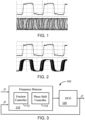
- FIG. 2 shows an exemplary diagram showing a single frequency clock signal for driving a transmitter and a spread-spectrum synchronous clock signal for driving a receiver according to some embodiments of the present disclosure. As shown in FIG. 2 , although an outputted clock signal has multiple phase relationship with original input signal, it will not exceed a preset boundary in the spread spectrum.
- the output signal and the input signal are considered to be substantially synchronous to each other.
- the data-establishing time and data maintaining time for the receiving data can be provided sufficiently in time under the spread-spectrum synchronous clock signal, the data can be securely transmitted from the transmitter to the receiver.
- FIG. 3 is a block diagram of a circuit for generating spread-spectrum synchronous clock signal in a frequency locked loop according to an embodiment of the present disclosure.
- the circuit for generating spread-spectrum synchronous clock signal in a frequency locked loop is referred to a spread-spectrum clock signal generator.
- the spread-spectrum clock signal generator 100 includes a frequency detector 110 and a digitally controlled oscillator 120 coupled together in a loop of feedback. An input signal with a first frequency f 1 is loaded and received by the frequency detector 110 and a feedback signal with a second frequency f 2 coming out of the clock signal generator 100 is reloaded in the frequency detector 110.
- the loop of feedback is a frequency locking loop for making the second frequency f 2 of the feedback signal to track the first frequency f 1 of the input signal.
- the digitally controlled oscillator 120 is provided as a direct period synthesizer that is based on a base time unit ⁇ and controlled by a digital frequency control word F to select one of multiple (K) input pulses of an input frequency f in with equally spaced phase of ⁇ to form a synthesized periodic signal at its output port (which is then provided as the feedback signal).
- the frequency control word (or simply called control word) F is a number between 2 and 2K.
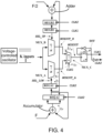
- FIG. 4 shows a functional diagram of a digitally controlled oscillator according to an embodiment of the present disclosure.
- the K input pulses are generated by a simple voltage-controlled oscillator.
- the K input pulses are based on the base time unit ⁇ which is created from K phase-evenly-spaced signals with a same frequency f in .
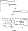
- FIG. 5 shows a schematic diagram of K input pulses for the digitally controlled oscillator of FIG. 4 according to an embodiment of the present disclosure.
- the base time unit is achieved with a circuit including a ring of K-stage cross-NANDs.
- the base time unit is also made from an inverter chain, a Johnson counter, or a delayed locked loop.
- the K input pulses are inputted respectively to two K-to-1 multiplexers.
- a first K-to-1 multiplexer (MUX__A) at a lower half of the figure is coupled to a 2-pipeline register controlled by the control word F via an accumulator to allow the K input pulses to pass through a lower path as a first output MUXOUT_A.
- the accumulator performs accumulation computation every rising edge of clock signal to handle that the control word F is a real number including a fraction part r beyond an integer part I .
- the K-to-1 multiplexer in the lower path dominates the length of logic '0' of output CLK1 at a low voltage level.
- the SEL_LOW is fed into the first (or lower) K-to-1 multiplexer at a rising edge of CLK2. So, it will choose one pulse of the K pulses to be the first output.
- a second K-to-1 multiplexer (MUXB) is coupled to a 2-pipeline register controlled by the half control word F /2 via an adder to input the K pulses through an upper path for generating a high level of a second output MUXOUT_B.
- the adder only has the integer part of the control word F.
- the K-to-1 multiplexer in the upper path dominates the length of logic '1' of output CLK1 at a high voltage level.
- a 2-to-1 multiplexer is controlled by CLK1 to control the transition of upper path and lower path.
- CLK1 the transition of upper path and lower path.
- a toggle flip-flop circuit which includes a D-type flip-flop DFF and two inverters to toggle the output MUXOUT at every rising edge of clock signal, from '1' to '0' or from '0' to '1'.
- the chosen signal passes the first multiplexer MUX_A and is fed into the 2-to-1 multiplexer.
- t3 which occurs simultaneously with t2, when CLK2 is at the state of logic '1' after rising edge, the CLK1 is at the state of logic '0'.
- the 2-to-1 multiplexer chooses the second output MUXOUT_B from the upper path as MUXOUT sent to the toggle flip-flop.
- the rising edge of the second output MUXOUT_B arrives at the toggle flip-flop which finishes the transition from 0 to 1.
- CLK1 now is transited to 1. So the 2-to-1 multiplexer chooses the first output MUXOUT_A of the lower path to send to the toggle flip-flop. The whole process repeat itself.
- TAF time-average frequency
- the control word F is controlled or selected by the frequency detector 110 in the loop of feedback with a frequency lock mechanism.
- the first frequency f 1 of the input signal for the loop of feedback is the same as the input frequency f in of the K input pulses for the digitally controlled oscillator 120 and the second frequency f 2 of the feedback signal is dynamically selected from one time-average frequency f TAF outputted from the digitally controlled oscillator 120.
- the frequency detector 110 includes a fraction controller 112 configured to compare the input signal of the first frequency f 1 with the feedback signal of the second frequency f 2 to generate a first control signal fast and a second control signal slow alternately for determining an integer part I of the control word F in the loop of feedback to enable a tracking of the second frequency f 2 to the first frequency f 1.
- FIG. 6 shows a functional diagram of a fraction controller according to an embodiment of the present disclosure.
- the fraction controller 112 includes a first input port receiving the input signal, and a second input port receiving the feedback signal. Additionally, the fraction controller 112 includes a trigger sub-circuit 1121 coupled to the first input port and the second input port and configured to detect a relationship between the first frequency f 1 and the second frequency f 2.
- the fraction controller 112 further includes a combined logic sub-circuit 1122 coupled to the trigger sub-circuit 1121 to generate the first control signal fast to a first control port in a first timeframe t A and the second control signal slow to a second control port in a second timeframe t B .
- the first timeframe t A and second timeframe t B alternately appearing one after other.
- the trigger sub-circuit 1121 includes four D-type flip-flops coupled to the first input port via a power-divider and to the second input port partially via an inverter.
- the trigger sub-circuit 1121 is configured to determine the first frequency f 1 being greater/smaller than the second frequency f 2.
- the combined logic sub-circuit 1122 includes two XOR gates, two inverters, and two AND gates configured to output either the first control signal fast to the first control port in the first timeframe t A based on determination that the first frequency f 1 is greater than the second frequency f 2 or the second control signal slow to the second control port in the second timeframe t B based on determination that the first frequency f 1 is smaller than the second frequency f 2.
- the first control signal fast is driving to shrink the control word F and the second control signal slow is driving to enlarge the control word F, in the loop of feedback.
- the whole loop of feedback reaches a dynamic equilibrium as the first control signal fast and the second control signal slow are alternately generated and the control word F is switched between two integers I and I +1, as shown schematically in FIG. 7 .
- the fraction controller 112 is operated to select different integer I , and different ratio of N A and N B to determine the frequency locking.
- the fraction controller 112 achieves a substantial real-time frequency locking in the loop of feedback.
- the frequency detector 110 also includes a phase-shift controller 114 configured to generate a spread-spectrum signal by providing n register levels for the first control signal fast and the second control signal slow generated by the fraction controller 112.
- the phase-shift controller 114 introduces n phase delays to each of the first control signal fast and the second control signal slow for providing extra multiple options to the fraction part r of the control word F.
- FIG. 8 is a functional diagram of a phase-shift controller according to an embodiment of the present disclosure.
- the phase-shift controller 114 includes an n-level cache sub-circuit configured to receive the first control signal fast to generate total n levels of first register-delayed control signals, or receive the second control signal slow to generate total n levels of second register-delayed control signals.
- the n-level cache sub-circuit includes a first group of D-type flip-flops 1140-1 having n stages connected in series configured to receive the first control signal fast at a first stage of the n stages of the first group of D-type flip-flops 1140-1 and to receive the feedback signal f 2 at each of the n stages of the first group of D-type flip-flops 1140-1, to generate the n levels of first register-delayed control signals. For example, it outputs fast1 in a first stage, fast2 in a second stage, fast3 in a third stage, ..., fastn-1 in a (n-1)-th stage, and fastn in a n-th stage.
- the n-level cache sub-circuit includes a second group of D-type flip-flops 1140-2 having n stages connected in series configured to receive the second control signal slow at the first stage of the n stages of the second group of D-type flip-flops 1140-2 and to receive the feedback signal f 2 at each of the n stages of the second group of D-type flip-flops 1140-2, to generate the n levels of second register-delayed control signals, i.e., slow1 in a first stage, slow2 in a second stage, slow3 in a third stage, ..., slown-1 in a (n-1)-th stage, and slown in a n-th stage.
- Each of the second n stages can be one path selected randomly to give a register-delayed control signal with a respectively phase delay. Additionally, the first control signal fast and the n levels of first register-delayed control signals, denoted in general as fast [0:n] , and the second control signal slow and the n levels of second register-delayed control signals, denoted in general as slow [0:n] are fed into a controller 1142.
- the phase-shift controller 114 also includes a pseudo random binary sequence (PRBS) generator 1141 to randomly select a fraction number to drive the controller 1142 to select any specific path associated with the n levels of the first register-delayed control signals and the n levels of the second register-delayed control signals.
- PRBS pseudo random binary sequence
- the extra phase delay via the fraction number r for the control word F spreads the frequency spectrum.
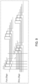
- FIG. 9 shows an exemplary diagram showing four possible options of a first cycle period under a 4-level cache registration delays according to an embodiment of the present disclosure. Every cache registration corresponds to an addition of a delay line to cause a phase offset ⁇ between input and output.
- ⁇ A T ⁇ T A
- ⁇ B T B ⁇ T
- t A has four optional values, i.e., contains four different numbers, N A , N A +1, N A +2, N A +3, of pules with period T A upon four options of selections among fast0, fast1, fast2, fast3 in the first 4-level register-delayed control signals or four options of selections among slow0, slow1, slow2, and slow3 in the second 4-level register-delayed control signals.
- N A and N B can be selected from four optional values respectively, N A ⁇ N A , N A + 1 , N A + 2 , N A + 3 ; N B ⁇ N B , N B + 1 , N B + 2 , N B + 3 Therefore, different combination of N A and N B can cause changes in the fraction number r.
- the phase-shift controller 114 uses a PRBS generator 1141 to randomly select a value of fraction r for the 4-level cache sub-circuit to determine respective paths for the register-delayed control signals. The randomness of the selection of fraction r increases randomness of the output frequency, achieving a spectrum spreading or broadening.
- phase-shift controller 114 Before using the phase-shift controller 114 for broadening the spectrum, with the control word F being switched back and forth between only integer value I and I +1 for substantially locking the output frequency of the synthesized periodic signal to the input frequency, a moderate frequency broadening has occurred as a Boundary 1 in FIG. 10 around the input frequency.
- the phase-shift controller 114 is introduced to randomly select a value of the fraction part r of the control word F, the spectrum is spread even larger with a broadened frequency boundary.
- a maximum phase shift value ⁇ max ⁇ of the feedback signal leading the input signal in phase is equal to N A ⁇ (T - T A ) and a maximum phase shift value ⁇ max + of the feedback signal lagging behind the input signal in phase is equal to N B ⁇ (T B - T).
- a more broadened boundary, Boundary 2 is provided to the output signal when the phase-shift controller 114 is included in the frequency detector 110. Because N A and N B have wider value ranges, the maximum phase shift values for the second frequency f 2 leading or lagging the first frequency f 1 become larger, resulting a more broadened boundary for the second frequency that substantially tracks the first frequency.
- the synthesized periodic signal with the time-average frequency that is substantially locked to the input frequency around a broadened boundary in frequency spectrum can be outputted as a synchronous clock signal.
- This clock signal can be used to drive synchronized data transmission at the receiver without worrying about data reception reliability and data transmission security.
- the broadened boundary of the spread-spectrum clock signal help to reduce radiated energy by spreading the power to wider range of frequencies. At the same time, it can be made to satisfy the following conditions for successful synchronous data transmission.
- FIG. 11 shows a schematic diagram of a spread-spectrum synchronous clock signal for driving secured data transmission according to an embodiment of the present disclosure. Referring to FIG.
- an input signal has a first frequency f1 and an output signal generated by the synchronous clock signal generator circuit described herein ( FIG. 3 through FIG. 10 ) has a second frequency f2 corresponding to a period of T.
- the second frequency f2 substantially tracks the first frequency f1, yet with a broadened boundary.
- the broadened boundary has a maximum value of ⁇ max ⁇ + ⁇ max + .
- L1 is a time period counting from a falling edge of the first frequency to an earliest rising edge of the second frequency and L2 is a time period counting from a latest rising edge of the second frequency to the falling edge of the first frequency. If the time-length of time period L1 is set to be longer than a data-establishing time for the receiver to receive the data and the time-length of time period L2 is set to be longer than a data-maintaining time for the receiver to receive the data, this synchronous clock signal can be securely used to drive data transmission.
- the present disclosure provides a chip for functionally generating spread-spectrum synchronous clock signal.
- the chip includes a circuit described herein and is implemented in Field Programmable Gate Arrays (FPGA).
- the chip can also be implemented in an application-specific integrated circuit (ASIC).
- ASIC application-specific integrated circuit
- the chip has a full digital circuitry structure made by a few cache registers and composite logic circuits with advantages in high efficiency, simple design, small volume to achieve real-time spectrum spreading for synthesizing clock signals. It suppresses electromagnetic interference radiated energy while maintaining system performance and data transmission security, applicable in many integrate circuit designs.
- the present disclosure provides a method for generating spread-spectrum synchronous clock signals.
- the method can be executed based on the circuit described herein, shown in FIG. 3 through FIG. 11 .
- the method includes providing an input signal of a first frequency and generating multiple pulses of the first frequency with equally spaced phase delay ⁇ .
- the method further includes obtaining a synthesized periodic signal with a time-average frequency from one of the multiple pulses controlled by a control word F.
- the synthesized periodic signal is used as a feedback signal.
- the method includes comparing the input signal of the first frequency with the feedback signal of a second frequency in a loop of feedback.
- the method also includes generating a first control signal and a second control signal alternately in a first timeframe and a second timeframe one after another based on relationship between the first frequency and the second frequency.
- the method further includes updating an integer part I of the control word F based on the first control signal or the second control signal to allow the second frequency to track the first frequency.
- the method includes generating multiple delays in respective first control signal and the second control signal.
- the method further includes selecting a fraction part r of the control word F randomly based on the multiple delays to provide a broadened phase boundary of a spread spectrum.
- the method includes outputting a clock signal based on the synthesized periodic signal with the time-average frequency being locked by the control word F within I and I +1 at a dynamic equilibrium in the loop of feedback.
- the step of obtaining a synthesized periodic signal with a time-average frequency includes using a first K-to-1 multiplexer coupled to an accumulation-register controlled by the control word F via an accumulator in a first path to input K pulses of the first frequency with equally spaced phase delay ⁇ , generating a low level of the synthesized periodic signal, using a second K-to-1 multiplexer coupled to an adder-register controlled by the half control word F /2 via an adder in a second path to input the K pulses of the first frequency with equally spaced phase delay ⁇ , generating a high level of the synthesized periodic signal, and using a 2-to-1 multiplexer to interlock the first path and the second path to output either the high level or the low level of the synthesized periodic signal.
- the step of generating a first control signal and a second control signal includes operating a fraction controller to output the first control signal in a first timeframe based on determination that the first frequency is greater than the second frequency and output the second control signal in a second timeframe based on determination that the first frequency is smaller than the second frequency.
- the step of updating an integer part I of the control word F includes reducing the integer part I triggered by the first control signal in the first timeframe and increasing the integer part I triggered by the second control signal in the second timeframe.
- the step of generating multiple delays in respective first control signal and the second control signal includes forming a first group of D-type flip-flops having n stages connected in series to receive the first control signal at the first one of the n stages of the first group of D-type flip-flops and to receive the feedback signal at each of the n stages of the first group of D-type flip-flops, generating n levels of first register-delayed control signals; forming a second group of D-type flip-flops having n stages connected in series to receive the second control signal at the first one of the n stages of the second group of D-type flip-flops and to receive the feedback signal at each of the n stages of the second group of D-type flip-flops, and generating n levels of second register-delayed control signals.
- the step of selecting a fraction part r of the control word F randomly based on the multiple delays further includes selecting randomly one of the first register-delayed control signals using a pseudo random binary sequence (PRBS) generator to drive a controller to control a number of output pulses with a first period in the first timeframe, and selecting randomly one of the second register-delayed control signals using a pseudo random binary sequence (PRBS) generator to drive the controller to control a number of output pulses with a second period in the second timeframe.
- PRBS pseudo random binary sequence
- the term "the invention”, “the present invention” or the like does not necessarily limit the claim scope to a specific embodiment, and the reference to exemplary embodiments of the invention does not imply a limitation on the invention, and no such limitation is to be inferred.
- the invention is limited only by the scope of the appended claims. Moreover, these claims may refer to use "first”, “second”, etc. following with noun or element. Such terms should be understood as a nomenclature and should not be construed as giving the limitation on the number of the elements modified by such nomenclature unless specific number has been given. Any advantages and benefits described may not apply to all embodiments of the invention.
Landscapes
- Engineering & Computer Science (AREA)
- Physics & Mathematics (AREA)
- General Engineering & Computer Science (AREA)
- Theoretical Computer Science (AREA)
- Computer Hardware Design (AREA)
- Computing Systems (AREA)
- Mathematical Physics (AREA)
- General Physics & Mathematics (AREA)
- Stabilization Of Oscillater, Synchronisation, Frequency Synthesizers (AREA)
Claims (15)
- Schaltung zum Erzeugen eines synchronen Spreizspektrum-Taktsignals in einem Frequenzregelkreis, wobei die Schaltung umfasst:einen Frequenzdetektor (110), umfassend eine Bruchsteuerung (112), die eingerichtet ist, um ein Eingangssignal einer ersten Frequenz mit einem Rückkopplungssignal einer zweiten Frequenz in einer Rückkopplungsschleife zu vergleichen, um abwechselnd ein erstes Steuersignal und ein zweites Steuersignal zu erzeugen, um einen ganzzahligen Teil I eines Steuerworts F zu bestimmen, um die erste Frequenz zu verfolgen, undumfassend eine Phasenverschiebungssteuerung (114), die eingerichtet ist, um n Pegel für das erste Steuersignal und das zweite Steuersignal zu registrieren, um n Phasenverzögerungen zum zufälligen Ändern eines Bruchteils r (0< r <1) des Steuerworts F einzuführen, um eine verbreiterte Grenze in einem Frequenzspektrum bereitzustellen; undeinen digital gesteuerten Oszillator, der eingerichtet ist, um ein synthetisiertes periodisches Signal mit der zweiten Frequenz basierend auf einer Basiszeiteinheit Δ, der ersten Frequenz und dem Steuerwort F zu erzeugen, wobei das synthetisierte periodische Signal als Rückkopplungssignal in der Rückkopplungsschleife rückgekoppelt und mit der zweiten Frequenz ausgegeben wird, die innerhalb der erweiterten Grenze der ersten Frequenz verriegelt ist.
- Schaltung nach Anspruch 1, wobei der digital gesteuerte Oszillator eingerichtet ist, um K Impulse der ersten Frequenz mit einer gleichmäßig beabstandeten Phasenverschiebung von Δ zu erzeugen, so dass unter der Steuerung des Steuerworts F (2 ≤ F ≤ 2K) das synthetisierte periodische Signal aus einem der K Impulse mit einer durchschnittlichen Periode T = F•Δ und der zweiten Frequenz ausgewählt wird, wobei die zweite Frequenz eine Zeitdurchschnittsfrequenz gleich K/F multipliziert mit der ersten Frequenz ist; und/oder wobei die Bruchsteuerung (112) einen ersten Eingangsanschluss, der das Eingangssignal empfängt, einen zweiten Eingangsanschluss, der das Rückkopplungssignal empfängt, eine Auslöser-Teilschaltung (1121), die mit dem ersten Eingangsanschluss und dem zweiten Eingangsanschluss gekoppelt ist und eingerichtet ist, um eine Beziehung zwischen der ersten Frequenz und der zweiten Frequenz zu erfassen, eine kombinierte Logik-Teilschaltung (1122), die mit der Auslöser-Teilschaltung (1121) gekoppelt ist, um das erste Steuersignal an einen ersten Steueranschluss in einem ersten Zeitrahmen und das zweite Steuersignal an einen zweiten Steueranschluss in einem zweiten Zeitrahmen zu erzeugen, wobei der erste Zeitrahmen und der zweite Zeitrahmen abwechselnd nacheinander auftreten, umfasst.
- Schaltung nach Anspruch 2, wobei die Auslöser-Teilschaltung (1121) vier D-Typ-Flipflops umfasst, die mit dem ersten Eingangsanschluss über einen Leistungsteiler und mit dem zweiten Eingangsanschluss teilweise über einen Wechselrichter gekoppelt sind, eingerichtet, um zu bestimmen, ob die erste Frequenz größer oder kleiner als die zweite Frequenz ist, und die kombinierte Logik-Teilschaltung (1122) zwei XOR-Gatter, zwei Wechselrichter und zwei UND-Gatter umfasst, die eingerichtet sind, um entweder das erste Steuersignal an den ersten Steueranschluss in dem ersten Zeitrahmen basierend auf einer Bestimmung, dass die erste Frequenz größer als die zweite Frequenz ist, oder das zweite Steuersignal an den zweiten Steueranschluss in dem zweiten Zeitrahmen basierend auf einer Bestimmung, dass die erste Frequenz kleiner als die zweite Frequenz ist, auszugeben.
- Schaltung nach Anspruch 3, wobei das erste Steuersignal dazu dient, ein Reduzieren des Steuerworts F in dem ersten Zeitrahmen zu steuern, und das zweite Steuersignal dazu dient, ein Erhöhen des Steuerworts F in dem zweiten Zeitrahmen zu steuern, so dass das Steuerwort F zwischen I und I+1 umgeschaltet wird, wenn die Rückkopplungsschleife ein dynamisches Gleichgewicht erreicht, wobei ein erster Zeitrahmen und ein zweiter Zeitrahmen abwechselnd nacheinander auftreten.
- Schaltung nach Anspruch 4, wobei das dynamische Gleichgewicht einen ersten Zeitrahmen und einen zweiten Zeitrahmen umfasst, die im Durchschnitt abwechselnd nacheinander auftreten, basierend auf einer Anzahl NA von Ausgangsimpulsen mit einer ersten Periode TA = I•Δ in dem ersten Zeitrahmen und einer Anzahl NB von Ausgangsimpulsen mit einer zweiten Periode TB = (I+1)•Δ in dem zweiten Zeitrahmen, wobei die Bruchzahl r das Verhältnis von NB zu einer Summe von NA und NB ergibt.
- Schaltung nach Anspruch 5, wobei die
Phasenverschiebungssteuerung (114) eine Zwischenspeicher-Teilschaltung für n Pegel umfasst, die eingerichtet ist, um das erste Steuersignal zu empfangen, um insgesamt n Pegel von ersten registerverzögerten Steuersignalen zu erzeugen, oder das zweite Steuersignal zu empfangen, um insgesamt n Pegel von zweiten registerverzögerten Steuersignalen zu erzeugen; einen Pseudozufalls-Binärsequenz-Generator (PRBS-Generator) (1141), um einen Wert der Bruchzahl r zufällig auszuwählen; und eine Steuerungs-Teilschaltung, die eingerichtet ist, um einen beliebigen Pfad auszuwählen, der den n Pegeln der ersten registerverzögerten Steuersignale und den n Pegeln der zweiten registerverzögerten Steuersignale zugeordnet ist, und den Wert der Bruchzahl r zu empfangen, um das Steuerwort F zu bestimmen, umfasst. - Schaltung nach Anspruch 6, wobei die Zwischenspeicher-Teilschaltung für n Pegel eine erste Gruppe von D-Typ-Flipflops (1140-1) mit n Stufen umfasst, die in Reihe geschaltet und eingerichtet sind, um das erste Steuersignal an einer ersten Stufe der n Stufen der ersten Gruppe von D-Typ-Flipflops (1140-1) zu empfangen und das Rückkopplungssignal an jeder der n Stufen der ersten Gruppe von D-Typ-Flipflops (114 0-1) zu empfangen, um die n Pegel erster registerverzögerter Steuersignale zu erzeugen, und eine zweite Gruppe von D-Typ-Flipflops (1140-2) mit n Stufen umfasst, die in Reihe geschaltet und eingerichtet sind, um das zweite Steuersignal an der ersten Stufe der n Stufen der zweiten Gruppe von D-Typ-Flipflops (1140-2) zu empfangen und das Rückkopplungssignal an jeder der n Stufen der zweiten Gruppe von D-Typ-Flipflops (1140-2) zu empfangen, um die n Pegel zweiter registerverzögerter Steuersignale zu erzeugen;
wobei die Zwischenspeicher-Teilschaltung für n Pegel optional n Auswahlmöglichkeiten von NA und n Auswahlmöglichkeiten von NB einführt und ein zufällig ausgewählter r = NB/(NA + NB) die erweiterte Grenze bereitstellt, die durch einen Maximalwert des Rückkopplungssignals, das dem Eingangssignal in der Phase vorauseilt, als NA•(T - TA) und einen Maximalwert des Rückkopplungssignals, das dem Eingangssignal in der Phase nacheilt, als NB•(TB - T) definiert ist. - Schaltung nach Anspruch 2, wobei der digital gesteuerte Oszillator einen spannungsgesteuerten Oszillator zum Erzeugen der K Impulse mit gleichmäßig beabstandeter Phase, einen ersten K-zu-1-Multiplexer (MUX_A), der mit einem Akkumulatorregister gekoppelt ist, das durch das Steuerwort F über einen Akkumulator gesteuert wird, um die K Impulse über einen unteren Pfad einzugeben, zum Erzeugen eines niedrigen Pegels des synthetisierten periodischen Signals, einen zweiten K-zu-1-Multiplexer (MUXB), der mit einem Addiererregister gekoppelt ist, das durch das halbe Steuerwort F/2 über einen Addierer gesteuert wird, um die K-Impulse über einen oberen Pfad einzugeben und einen hohen Pegel des synthetisierten periodischen Signals zu erzeugen, einen 2-zu-1-Multiplexer, um einen Übergang zwischen dem oberen Pfad und dem unteren Pfad zu steuern und das synthetisierte periodische Signal auszugeben, umfasst.
- Schaltung nach Anspruch 8, wobei das synthetisierte periodische Signal als ein Spreizspektrum-Taktsignal übertragen wird, da die zweite Frequenz im Wesentlichen synchron zu der ersten Frequenz ist, unter der Bedingung, dass eine Datenempfangs-Einrichtungszeit kürzer ist als die Hälfte der Periode T minus einem Maximalwert des synthetisierten periodischen Signals, das dem Eingangssignal in der Phase vorauseilt, und eine Datenempfangs-Aufrechterhaltungszeit kürzer ist als die Hälfte der Periode T minus einem Maximalwert des synthetisierten periodischen Signals, das dem Eingangssignal in der Phase nacheilt; und/oder wobei der digital gesteuerte Oszillator ferner einen T-Flipflop umfasst, der mit dem 2-zu-1-Multiplexer gekoppelt ist, um den Übergang des oberen Pfads und des unteren Pfads umzuschalten.
- Chip zum funktionalen Erzeugen eines synchronen Spreizspektrum-Taktsignals, dadurch gekennzeichnet, dass der Chip die Schaltung nach einem der Ansprüche 1 bis 9 umfasst, die in feldprogrammierbaren Gate Arrays (FPGA) und/oder in einer anwendungsspezifischen integrierten Schaltung (ASIC) implementiert ist.
- Verfahren zum Erzeugen von synchronen Spreizspektrum-Taktsignalen, wobei das Verfahren umfasst:Bereitstellen eines Eingangssignals einer ersten Frequenz;Erzeugen mehrerer Impulse der ersten Frequenz mit gleichmäßig beabstandeter Phasenverzögerung Δ;Erhalten eines synthetisierten periodischen Signals mit einer Zeitdurchschnittsfrequenz von einem der mehreren Impulse, die durch ein Steuerwort F gesteuert werden,wobei das synthetisierte periodische Signal als Rückkopplungssignal verwendet wird;Vergleichen des Eingangssignals der ersten Frequenz mit dem Rückkopplungssignal einer zweiten Frequenz in einer Rückkopplungsschleife;Erzeugen eines ersten Steuersignals und eines zweiten Steuersignals abwechselnd in einem ersten Zeitrahmen und einem zweiten Zeitrahmen nacheinander, basierend auf einer Beziehung zwischen der ersten Frequenz und der zweiten Frequenz;Aktualisieren eines ganzzahligen Teils I des Steuerworts F basierend auf dem ersten Steuersignal oder dem zweiten Steuersignal, um es der zweiten Frequenz zu ermöglichen, die erste Frequenz zu verfolgen;Erzeugen mehrerer Verzögerungen in einem jeweiligen ersten Steuersignal und dem zweiten Steuersignal;Auswählen eines Bruchteils r des Steuerworts F zufällig basierend auf den mehreren Verzögerungen, um eine verbreiterte Phasengrenze eines Spreizspektrums bereitzustellen; undAusgeben eines Taktsignals basierend auf dem synthetisierten periodischen Signal, wobei die Zeitdurchschnittsfrequenz durch das Steuerwort F innerhalb von I und I+1 in einem dynamischen Gleichgewicht in der Rückkopplungsschleife verriegelt wird.
- Verfahren nach Anspruch 11, wobei das Erhalten eines synthetisierten periodischen Signals mit einer Zeitdurchschnittsfrequenz ein Verwenden eines ersten K-zu-1-Multiplexers (MUX_A), der mit einem Akkumulatorregister gekoppelt ist, das durch das Steuerwort F über einen Akkumulator in einem ersten Pfad gesteuert wird, um K Impulse der ersten Frequenz mit gleichmäßig beabstandeter Phasenverzögerung Δ einzugeben, ein Erzeugen eines niedrigen Pegels des synthetisierten periodischen Signals, ein Verwenden eines zweiten K-zu-1-Multiplexers (MUXB), der mit einem Addierer-Register gekoppelt ist, das durch das halbe Steuerwort F/2 über einen Addierer in einem zweiten Pfad gesteuert wird, um die K Impulse der ersten Frequenz mit gleichmäßig beabstandeter Phasenverzögerung Δ einzugeben, ein Erzeugen eines hohen Pegels des synthetisierten periodischen Signals, ein Verwenden eines 2-zu-1-Multiplexers, um den ersten Pfad und den zweiten Pfad miteinander zu verriegeln, um entweder den hohen Pegel oder den niedrigen Pegel des synthetisierten periodischen Signals auszugeben, umfasst.
- Verfahren nach Anspruch 11, wobei das Erzeugen eines ersten Steuersignals und eines zweiten Steuersignals ein Betreiben einer Bruchsteuerung (112), um das erste Steuersignal in einem ersten Zeitrahmen basierend auf einer Bestimmung auszugeben, dass die erste Frequenz größer als die zweite Frequenz ist, und um das zweite Steuersignal in einem zweiten Zeitrahmen basierend auf einer Bestimmung auszugeben, dass die erste Frequenz kleiner als die zweite Frequenz ist, umfasst.
- Verfahren nach Anspruch 13, wobei das Aktualisieren eines ganzzahligen Teils I des Steuerworts F ein Reduzieren des ganzzahligen Teils I, der durch das erste Steuersignal in dem ersten Zeitrahmen ausgelöst wird, und ein Erhöhen des ganzzahligen Teils I, der durch das zweite Steuersignal in dem zweiten Zeitrahmen ausgelöst wird, umfasst.
- Verfahren nach Anspruch 11, wobei das Erzeugen mehrerer Verzögerungen in einem jeweiligen ersten Steuersignal und dem zweiten Steuersignal ein Bilden einer ersten Gruppe von D-Typ-Flipflops (1140-1) mit n Stufen, die in Reihe geschaltet sind, um das erste Steuersignal an der ersten der n Stufen der ersten Gruppe von D-Typ-Flipflops (1140-1) zu empfangen und das Rückkopplungssignal an jeder der n Stufen der ersten Gruppe von D-Typ-Flipflops (114 0-1) zu empfangen, ein Erzeugen von n Pegeln erster registerverzögerter Steuersignale, ein Bilden einer zweiten Gruppe von D-Typ-Flipflops (1140-2) mit n Stufen, die in Reihe geschaltet sind, um das zweite Steuersignal an der ersten der n Stufen der zweiten Gruppe von D-Typ-Flipflops (1140-2) zu empfangen und das Rückkopplungssignal an jeder der n Stufen der zweiten Gruppe von D-Typ-Flipflops (1140-2) zu empfangen, ein Erzeugen von n Pegeln zweiter registerverzögerter Steuersignale umfasst;
wobei optional das Auswählen eines Bruchteils r des Steuerworts F zufällig basierend auf den mehreren Verzögerungen ein zufälliges Auswählen eines der ersten registerverzögerten Steuersignale unter Verwendung eines Pseudozufalls-Binärsequenz-Generators (PRBS-Generators) (1141), um eine Steuerung (1142) anzusteuern, um eine Anzahl von Ausgangsimpulsen mit einer ersten Periode in dem ersten Zeitrahmen zu steuern, und ein zufälliges Auswählen eines der zweiten registerverzögerten Steuersignale unter Verwendung eines Pseudozufalls-Binärsequenz-Generators (PRBS-Generators) (1141), um die Steuerung (1142) anzusteuern, um eine Anzahl von Ausgangsimpulsen mit einer zweiten Periode in dem zweiten Zeitrahmen zu steuern, umfasst.
Applications Claiming Priority (1)
| Application Number | Priority Date | Filing Date | Title |
|---|---|---|---|
| PCT/CN2019/110152 WO2021068131A1 (en) | 2019-10-09 | 2019-10-09 | Digital clock signal generator, chip, and method for generating spread-spectrum synchronous clock signals |
Publications (3)
| Publication Number | Publication Date |
|---|---|
| EP4042256A1 EP4042256A1 (de) | 2022-08-17 |
| EP4042256A4 EP4042256A4 (de) | 2022-10-19 |
| EP4042256B1 true EP4042256B1 (de) | 2025-05-14 |
Family
ID=75436907
Family Applications (1)
| Application Number | Title | Priority Date | Filing Date |
|---|---|---|---|
| EP19948613.5A Active EP4042256B1 (de) | 2019-10-09 | 2019-10-09 | Digitaler taktsignalgenerator, chip und verfahren zur erzeugung von synchronen spreizspektrumstaktsignalen |
Country Status (5)
| Country | Link |
|---|---|
| US (1) | US11848679B2 (de) |
| EP (1) | EP4042256B1 (de) |
| JP (1) | JP7485698B2 (de) |
| CN (1) | CN113039504B (de) |
| WO (1) | WO2021068131A1 (de) |
Families Citing this family (4)
| Publication number | Priority date | Publication date | Assignee | Title |
|---|---|---|---|---|
| US12346148B2 (en) * | 2019-10-09 | 2025-07-01 | Beijing Boe Technology Development Co., Ltd. | Digital clock signal generator, chip, and method for generating spread-spectrum synchronous clock signals |
| CN114095166B (zh) * | 2021-11-23 | 2024-08-13 | 北京京东方技术开发有限公司 | 生成节点临时身份标识的方法、节点及系统 |
| CN114281304B (zh) * | 2022-01-12 | 2026-01-06 | 北京京东方技术开发有限公司 | 随机计算方法、电路、芯片及设备 |
| CN114385111B (zh) * | 2022-01-17 | 2025-09-23 | 北京京东方技术开发有限公司 | 随机计算电路及方法 |
Family Cites Families (19)
| Publication number | Priority date | Publication date | Assignee | Title |
|---|---|---|---|---|
| US6940937B2 (en) * | 2001-12-24 | 2005-09-06 | Texas Instruments Incorporated | Scalable high-speed precision frequency and phase synthesis |
| CN1211929C (zh) * | 2002-01-30 | 2005-07-20 | 威盛电子股份有限公司 | 低功率消耗的高频时钟脉冲产生器 |
| US7356107B2 (en) * | 2004-01-26 | 2008-04-08 | Texas Instruments Incorporated | Flying-adder frequency synthesizer-based digital-controlled oscillator and video decoder including the same |
| US7893788B2 (en) * | 2008-02-19 | 2011-02-22 | Mediatek Inc. | Charge pump-based frequency modulator |
| US8022849B2 (en) * | 2008-04-14 | 2011-09-20 | Qualcomm, Incorporated | Phase to digital converter in all digital phase locked loop |
| US8269563B2 (en) * | 2008-06-10 | 2012-09-18 | Qualcomm Incorporated | Dithering a digitally-controlled oscillator output in a phase-locked loop |
| US8184762B2 (en) * | 2008-11-06 | 2012-05-22 | Iwatt, Inc. | Digital phase lock loop with multi-phase master clock |
| JP2011107750A (ja) * | 2009-11-12 | 2011-06-02 | Renesas Electronics Corp | 半導体集積回路装置 |
| US8378724B2 (en) * | 2010-12-22 | 2013-02-19 | Silicon Laboratories Inc. | Controlling a frequency locked loop |
| CN104012004A (zh) * | 2011-10-01 | 2014-08-27 | 英特尔公司 | 数字分数分频器 |
| US9036755B2 (en) * | 2012-09-28 | 2015-05-19 | Liming Xiu | Circuits and methods for time-average frequency based clock data recovery |
| US10063246B2 (en) * | 2016-11-16 | 2018-08-28 | Perceptia Devices, Inc. | Low-power fractional-N PLLs |
| CN108270437B (zh) * | 2017-01-04 | 2023-04-14 | 京东方科技集团股份有限公司 | 数控振荡器和基于数控振荡器的全数字锁频环和锁相环 |
| CN106708166B (zh) * | 2017-01-09 | 2020-03-10 | 京东方科技集团股份有限公司 | 信号生成器和信号生成方法 |
| US10090845B1 (en) * | 2017-03-28 | 2018-10-02 | Stmicroelectronics International N.V. | Fraction-N digital PLL capable of canceling quantization noise from sigma-delta modulator |
| CN107896107A (zh) * | 2017-10-13 | 2018-04-10 | 浙江大学 | 一种鉴频器以及一种同时锁定频率和相位的环路系统 |
| CN110199477B (zh) | 2019-04-23 | 2022-02-01 | 京东方科技集团股份有限公司 | 时钟展频电路、电子设备和时钟展频方法 |
| US11196454B2 (en) * | 2019-10-09 | 2021-12-07 | Beijing Boe Technology Development Co., Ltd. | Digital transceiver driven by synchronous spread spectrum clock signal for data transmission |
| CN111446962B (zh) * | 2020-04-03 | 2023-12-12 | 京东方科技集团股份有限公司 | 时钟信号产生电路、时钟信号产生方法及电子设备 |
-
2019
- 2019-10-09 US US16/975,258 patent/US11848679B2/en active Active
- 2019-10-09 JP JP2021567872A patent/JP7485698B2/ja active Active
- 2019-10-09 CN CN201980001917.4A patent/CN113039504B/zh active Active
- 2019-10-09 EP EP19948613.5A patent/EP4042256B1/de active Active
- 2019-10-09 WO PCT/CN2019/110152 patent/WO2021068131A1/en not_active Ceased
Also Published As
| Publication number | Publication date |
|---|---|
| US11848679B2 (en) | 2023-12-19 |
| US20230123009A1 (en) | 2023-04-20 |
| CN113039504A (zh) | 2021-06-25 |
| EP4042256A4 (de) | 2022-10-19 |
| CN113039504B (zh) | 2024-08-20 |
| EP4042256A1 (de) | 2022-08-17 |
| WO2021068131A1 (en) | 2021-04-15 |
| JP2023503754A (ja) | 2023-02-01 |
| JP7485698B2 (ja) | 2024-05-16 |
Similar Documents
| Publication | Publication Date | Title |
|---|---|---|
| EP4042256B1 (de) | Digitaler taktsignalgenerator, chip und verfahren zur erzeugung von synchronen spreizspektrumstaktsignalen | |
| EP4042578B1 (de) | Digitaler sender-empfänger mit antrieb durch synchrones spreizspektrumtaktsignal für datenübertragung | |
| US10389303B2 (en) | Integrated circuit comprising fractional clock multiplication circuitry | |
| US6674772B1 (en) | Data communications circuit with multi-stage multiplexing | |
| US7924071B2 (en) | Synchronization detection circuit, pulse width modulation circuit using the same, and synchronization detection method | |
| US10979057B1 (en) | Delay lock loop and phase locking method thereof | |
| US6150859A (en) | Digital delay-locked loop | |
| EP0757445A2 (de) | Frequenzsynthetisierer mit einem Phasenregelkreis | |
| EP4049370B1 (de) | Digitale taktschaltung zur erzeugung eines hochfrequenzvervielfachungstaktsignals | |
| TWI495266B (zh) | 環型振盪器電路 | |
| US12346148B2 (en) | Digital clock signal generator, chip, and method for generating spread-spectrum synchronous clock signals | |
| EP1260899A2 (de) | Schaltung und Methode zur Erzeugung eines verzögerten internen Taktsignals | |
| KR100923212B1 (ko) | 디지털-위상 변환기를 위한 방법 및 장치 | |
| JPWO2021068133A5 (de) | ||
| KR100903369B1 (ko) | 반도체 메모리 장치 | |
| JP2007053685A (ja) | 半導体集積回路装置 | |
| KR100937716B1 (ko) | 지연 고정 루프 기반의 주파수 체배 장치 및 방법 | |
| US6993103B2 (en) | Method for synchronizing clock and data signals | |
| US7253674B1 (en) | Output clock phase-alignment circuit | |
| TWI388129B (zh) | 全數位頻率合成裝置 | |
| CA2538959A1 (en) | Digital fractional clock divider |
Legal Events
| Date | Code | Title | Description |
|---|---|---|---|
| STAA | Information on the status of an ep patent application or granted ep patent |
Free format text: STATUS: THE INTERNATIONAL PUBLICATION HAS BEEN MADE |
|
| PUAI | Public reference made under article 153(3) epc to a published international application that has entered the european phase |
Free format text: ORIGINAL CODE: 0009012 |
|
| STAA | Information on the status of an ep patent application or granted ep patent |
Free format text: STATUS: REQUEST FOR EXAMINATION WAS MADE |
|
| 17P | Request for examination filed |
Effective date: 20210527 |
|
| AK | Designated contracting states |
Kind code of ref document: A1 Designated state(s): AL AT BE BG CH CY CZ DE DK EE ES FI FR GB GR HR HU IE IS IT LI LT LU LV MC MK MT NL NO PL PT RO RS SE SI SK SM TR |
|
| A4 | Supplementary search report drawn up and despatched |
Effective date: 20220915 |
|
| RIC1 | Information provided on ipc code assigned before grant |
Ipc: H03L 7/185 20060101ALI20220909BHEP Ipc: H03L 7/087 20060101ALI20220909BHEP Ipc: G06F 1/04 20060101ALI20220909BHEP Ipc: H03L 7/099 20060101ALI20220909BHEP Ipc: H03L 7/093 20060101ALI20220909BHEP Ipc: H03L 7/089 20060101ALI20220909BHEP Ipc: H03L 7/08 20060101ALI20220909BHEP Ipc: G06F 1/03 20060101AFI20220909BHEP |
|
| DAV | Request for validation of the european patent (deleted) | ||
| DAX | Request for extension of the european patent (deleted) | ||
| GRAP | Despatch of communication of intention to grant a patent |
Free format text: ORIGINAL CODE: EPIDOSNIGR1 |
|
| STAA | Information on the status of an ep patent application or granted ep patent |
Free format text: STATUS: GRANT OF PATENT IS INTENDED |
|
| INTG | Intention to grant announced |
Effective date: 20250211 |
|
| GRAS | Grant fee paid |
Free format text: ORIGINAL CODE: EPIDOSNIGR3 |
|
| GRAA | (expected) grant |
Free format text: ORIGINAL CODE: 0009210 |
|
| STAA | Information on the status of an ep patent application or granted ep patent |
Free format text: STATUS: THE PATENT HAS BEEN GRANTED |
|
| AK | Designated contracting states |
Kind code of ref document: B1 Designated state(s): AL AT BE BG CH CY CZ DE DK EE ES FI FR GB GR HR HU IE IS IT LI LT LU LV MC MK MT NL NO PL PT RO RS SE SI SK SM TR |
|
| REG | Reference to a national code |
Ref country code: GB Ref legal event code: FG4D |
|
| REG | Reference to a national code |
Ref country code: CH Ref legal event code: EP |
|
| REG | Reference to a national code |
Ref country code: DE Ref legal event code: R096 Ref document number: 602019070120 Country of ref document: DE |
|
| REG | Reference to a national code |
Ref country code: IE Ref legal event code: FG4D |
|
| REG | Reference to a national code |
Ref country code: NL Ref legal event code: MP Effective date: 20250514 |
|
| PG25 | Lapsed in a contracting state [announced via postgrant information from national office to epo] |
Ref country code: FI Free format text: LAPSE BECAUSE OF FAILURE TO SUBMIT A TRANSLATION OF THE DESCRIPTION OR TO PAY THE FEE WITHIN THE PRESCRIBED TIME-LIMIT Effective date: 20250514 Ref country code: ES Free format text: LAPSE BECAUSE OF FAILURE TO SUBMIT A TRANSLATION OF THE DESCRIPTION OR TO PAY THE FEE WITHIN THE PRESCRIBED TIME-LIMIT Effective date: 20250514 Ref country code: PT Free format text: LAPSE BECAUSE OF FAILURE TO SUBMIT A TRANSLATION OF THE DESCRIPTION OR TO PAY THE FEE WITHIN THE PRESCRIBED TIME-LIMIT Effective date: 20250915 |
|
| REG | Reference to a national code |
Ref country code: LT Ref legal event code: MG9D |
|
| PG25 | Lapsed in a contracting state [announced via postgrant information from national office to epo] |
Ref country code: GR Free format text: LAPSE BECAUSE OF FAILURE TO SUBMIT A TRANSLATION OF THE DESCRIPTION OR TO PAY THE FEE WITHIN THE PRESCRIBED TIME-LIMIT Effective date: 20250815 Ref country code: NO Free format text: LAPSE BECAUSE OF FAILURE TO SUBMIT A TRANSLATION OF THE DESCRIPTION OR TO PAY THE FEE WITHIN THE PRESCRIBED TIME-LIMIT Effective date: 20250814 |
|
| PG25 | Lapsed in a contracting state [announced via postgrant information from national office to epo] |
Ref country code: NL Free format text: LAPSE BECAUSE OF FAILURE TO SUBMIT A TRANSLATION OF THE DESCRIPTION OR TO PAY THE FEE WITHIN THE PRESCRIBED TIME-LIMIT Effective date: 20250514 Ref country code: PL Free format text: LAPSE BECAUSE OF FAILURE TO SUBMIT A TRANSLATION OF THE DESCRIPTION OR TO PAY THE FEE WITHIN THE PRESCRIBED TIME-LIMIT Effective date: 20250514 |
|
| REG | Reference to a national code |
Ref country code: AT Ref legal event code: MK05 Ref document number: 1795319 Country of ref document: AT Kind code of ref document: T Effective date: 20250514 |
|
| PG25 | Lapsed in a contracting state [announced via postgrant information from national office to epo] |
Ref country code: BG Free format text: LAPSE BECAUSE OF FAILURE TO SUBMIT A TRANSLATION OF THE DESCRIPTION OR TO PAY THE FEE WITHIN THE PRESCRIBED TIME-LIMIT Effective date: 20250514 |
|
| PG25 | Lapsed in a contracting state [announced via postgrant information from national office to epo] |
Ref country code: HR Free format text: LAPSE BECAUSE OF FAILURE TO SUBMIT A TRANSLATION OF THE DESCRIPTION OR TO PAY THE FEE WITHIN THE PRESCRIBED TIME-LIMIT Effective date: 20250514 |
|
| PG25 | Lapsed in a contracting state [announced via postgrant information from national office to epo] |
Ref country code: AT Free format text: LAPSE BECAUSE OF FAILURE TO SUBMIT A TRANSLATION OF THE DESCRIPTION OR TO PAY THE FEE WITHIN THE PRESCRIBED TIME-LIMIT Effective date: 20250514 |
|
| PG25 | Lapsed in a contracting state [announced via postgrant information from national office to epo] |
Ref country code: RS Free format text: LAPSE BECAUSE OF FAILURE TO SUBMIT A TRANSLATION OF THE DESCRIPTION OR TO PAY THE FEE WITHIN THE PRESCRIBED TIME-LIMIT Effective date: 20250814 |
|
| PG25 | Lapsed in a contracting state [announced via postgrant information from national office to epo] |
Ref country code: IS Free format text: LAPSE BECAUSE OF FAILURE TO SUBMIT A TRANSLATION OF THE DESCRIPTION OR TO PAY THE FEE WITHIN THE PRESCRIBED TIME-LIMIT Effective date: 20250914 |
|
| PG25 | Lapsed in a contracting state [announced via postgrant information from national office to epo] |
Ref country code: LV Free format text: LAPSE BECAUSE OF FAILURE TO SUBMIT A TRANSLATION OF THE DESCRIPTION OR TO PAY THE FEE WITHIN THE PRESCRIBED TIME-LIMIT Effective date: 20250514 |
|
| PGFP | Annual fee paid to national office [announced via postgrant information from national office to epo] |
Ref country code: DE Payment date: 20251021 Year of fee payment: 7 |
|
| PGFP | Annual fee paid to national office [announced via postgrant information from national office to epo] |
Ref country code: GB Payment date: 20251022 Year of fee payment: 7 |
|
| PG25 | Lapsed in a contracting state [announced via postgrant information from national office to epo] |
Ref country code: SM Free format text: LAPSE BECAUSE OF FAILURE TO SUBMIT A TRANSLATION OF THE DESCRIPTION OR TO PAY THE FEE WITHIN THE PRESCRIBED TIME-LIMIT Effective date: 20250514 Ref country code: DK Free format text: LAPSE BECAUSE OF FAILURE TO SUBMIT A TRANSLATION OF THE DESCRIPTION OR TO PAY THE FEE WITHIN THE PRESCRIBED TIME-LIMIT Effective date: 20250514 |
|
| PG25 | Lapsed in a contracting state [announced via postgrant information from national office to epo] |
Ref country code: CZ Free format text: LAPSE BECAUSE OF FAILURE TO SUBMIT A TRANSLATION OF THE DESCRIPTION OR TO PAY THE FEE WITHIN THE PRESCRIBED TIME-LIMIT Effective date: 20250514 |
|
| PG25 | Lapsed in a contracting state [announced via postgrant information from national office to epo] |
Ref country code: EE Free format text: LAPSE BECAUSE OF FAILURE TO SUBMIT A TRANSLATION OF THE DESCRIPTION OR TO PAY THE FEE WITHIN THE PRESCRIBED TIME-LIMIT Effective date: 20250514 |
|
| PG25 | Lapsed in a contracting state [announced via postgrant information from national office to epo] |
Ref country code: SK Free format text: LAPSE BECAUSE OF FAILURE TO SUBMIT A TRANSLATION OF THE DESCRIPTION OR TO PAY THE FEE WITHIN THE PRESCRIBED TIME-LIMIT Effective date: 20250514 |
|
| PG25 | Lapsed in a contracting state [announced via postgrant information from national office to epo] |
Ref country code: IT Free format text: LAPSE BECAUSE OF FAILURE TO SUBMIT A TRANSLATION OF THE DESCRIPTION OR TO PAY THE FEE WITHIN THE PRESCRIBED TIME-LIMIT Effective date: 20250514 |
|
| PG25 | Lapsed in a contracting state [announced via postgrant information from national office to epo] |
Ref country code: RO Free format text: LAPSE BECAUSE OF FAILURE TO SUBMIT A TRANSLATION OF THE DESCRIPTION OR TO PAY THE FEE WITHIN THE PRESCRIBED TIME-LIMIT Effective date: 20250514 |
|
| REG | Reference to a national code |
Ref country code: DE Ref legal event code: R097 Ref document number: 602019070120 Country of ref document: DE |
|
| PLBE | No opposition filed within time limit |
Free format text: ORIGINAL CODE: 0009261 |
|
| STAA | Information on the status of an ep patent application or granted ep patent |
Free format text: STATUS: NO OPPOSITION FILED WITHIN TIME LIMIT |
|
| REG | Reference to a national code |
Ref country code: CH Ref legal event code: L10 Free format text: ST27 STATUS EVENT CODE: U-0-0-L10-L00 (AS PROVIDED BY THE NATIONAL OFFICE) Effective date: 20260325 |
|
| 26N | No opposition filed |
Effective date: 20260217 |