EP4041994B1 - Strömungsmaschine zur luftversorgung eines brennstoffzellensystems, verfahren zum betreiben einer solchen strömungsmaschine - Google Patents
Strömungsmaschine zur luftversorgung eines brennstoffzellensystems, verfahren zum betreiben einer solchen strömungsmaschine Download PDFInfo
- Publication number
- EP4041994B1 EP4041994B1 EP20765235.5A EP20765235A EP4041994B1 EP 4041994 B1 EP4041994 B1 EP 4041994B1 EP 20765235 A EP20765235 A EP 20765235A EP 4041994 B1 EP4041994 B1 EP 4041994B1
- Authority
- EP
- European Patent Office
- Prior art keywords
- air
- turbomachine
- shaft
- air channel
- compressor
- Prior art date
- Legal status (The legal status is an assumption and is not a legal conclusion. Google has not performed a legal analysis and makes no representation as to the accuracy of the status listed.)
- Active
Links
- 239000000446 fuel Substances 0.000 title claims description 14
- 238000000034 method Methods 0.000 title claims description 10
- 239000003570 air Substances 0.000 claims description 95
- 239000012080 ambient air Substances 0.000 claims description 11
- 238000001816 cooling Methods 0.000 claims description 11
- 239000011888 foil Substances 0.000 claims description 4
- 238000004804 winding Methods 0.000 claims description 4
- QVGXLLKOCUKJST-UHFFFAOYSA-N atomic oxygen Chemical compound [O] QVGXLLKOCUKJST-UHFFFAOYSA-N 0.000 description 2
- 230000006835 compression Effects 0.000 description 2
- 238000007906 compression Methods 0.000 description 2
- 239000007789 gas Substances 0.000 description 2
- 239000001301 oxygen Substances 0.000 description 2
- 229910052760 oxygen Inorganic materials 0.000 description 2
- XLYOFNOQVPJJNP-UHFFFAOYSA-N water Substances O XLYOFNOQVPJJNP-UHFFFAOYSA-N 0.000 description 2
- UFHFLCQGNIYNRP-UHFFFAOYSA-N Hydrogen Chemical compound [H][H] UFHFLCQGNIYNRP-UHFFFAOYSA-N 0.000 description 1
- 230000001133 acceleration Effects 0.000 description 1
- 238000006243 chemical reaction Methods 0.000 description 1
- 239000002131 composite material Substances 0.000 description 1
- 238000011161 development Methods 0.000 description 1
- 230000018109 developmental process Effects 0.000 description 1
- 239000012530 fluid Substances 0.000 description 1
- 239000001257 hydrogen Substances 0.000 description 1
- 229910052739 hydrogen Inorganic materials 0.000 description 1
- 238000012986 modification Methods 0.000 description 1
- 230000004048 modification Effects 0.000 description 1
Images

Classifications
-
- H—ELECTRICITY
- H02—GENERATION; CONVERSION OR DISTRIBUTION OF ELECTRIC POWER
- H02K—DYNAMO-ELECTRIC MACHINES
- H02K9/00—Arrangements for cooling or ventilating
- H02K9/02—Arrangements for cooling or ventilating by ambient air flowing through the machine
-
- F—MECHANICAL ENGINEERING; LIGHTING; HEATING; WEAPONS; BLASTING
- F01—MACHINES OR ENGINES IN GENERAL; ENGINE PLANTS IN GENERAL; STEAM ENGINES
- F01D—NON-POSITIVE DISPLACEMENT MACHINES OR ENGINES, e.g. STEAM TURBINES
- F01D25/00—Component parts, details, or accessories, not provided for in, or of interest apart from, other groups
- F01D25/16—Arrangement of bearings; Supporting or mounting bearings in casings
-
- F—MECHANICAL ENGINEERING; LIGHTING; HEATING; WEAPONS; BLASTING
- F04—POSITIVE - DISPLACEMENT MACHINES FOR LIQUIDS; PUMPS FOR LIQUIDS OR ELASTIC FLUIDS
- F04D—NON-POSITIVE-DISPLACEMENT PUMPS
- F04D29/00—Details, component parts, or accessories
- F04D29/26—Rotors specially for elastic fluids
- F04D29/28—Rotors specially for elastic fluids for centrifugal or helico-centrifugal pumps for radial-flow or helico-centrifugal pumps
- F04D29/284—Rotors specially for elastic fluids for centrifugal or helico-centrifugal pumps for radial-flow or helico-centrifugal pumps for compressors
-
- F—MECHANICAL ENGINEERING; LIGHTING; HEATING; WEAPONS; BLASTING
- F01—MACHINES OR ENGINES IN GENERAL; ENGINE PLANTS IN GENERAL; STEAM ENGINES
- F01D—NON-POSITIVE DISPLACEMENT MACHINES OR ENGINES, e.g. STEAM TURBINES
- F01D25/00—Component parts, details, or accessories, not provided for in, or of interest apart from, other groups
- F01D25/16—Arrangement of bearings; Supporting or mounting bearings in casings
- F01D25/166—Sliding contact bearing
- F01D25/168—Sliding contact bearing for axial load mainly
-
- F—MECHANICAL ENGINEERING; LIGHTING; HEATING; WEAPONS; BLASTING
- F02—COMBUSTION ENGINES; HOT-GAS OR COMBUSTION-PRODUCT ENGINE PLANTS
- F02C—GAS-TURBINE PLANTS; AIR INTAKES FOR JET-PROPULSION PLANTS; CONTROLLING FUEL SUPPLY IN AIR-BREATHING JET-PROPULSION PLANTS
- F02C6/00—Plural gas-turbine plants; Combinations of gas-turbine plants with other apparatus; Adaptations of gas-turbine plants for special use
- F02C6/04—Gas-turbine plants providing heated or pressurised working fluid for other apparatus, e.g. without mechanical power output
- F02C6/10—Gas-turbine plants providing heated or pressurised working fluid for other apparatus, e.g. without mechanical power output supplying working fluid to a user, e.g. a chemical process, which returns working fluid to a turbine of the plant
- F02C6/12—Turbochargers, i.e. plants for augmenting mechanical power output of internal-combustion piston engines by increase of charge pressure
-
- F—MECHANICAL ENGINEERING; LIGHTING; HEATING; WEAPONS; BLASTING
- F02—COMBUSTION ENGINES; HOT-GAS OR COMBUSTION-PRODUCT ENGINE PLANTS
- F02C—GAS-TURBINE PLANTS; AIR INTAKES FOR JET-PROPULSION PLANTS; CONTROLLING FUEL SUPPLY IN AIR-BREATHING JET-PROPULSION PLANTS
- F02C6/00—Plural gas-turbine plants; Combinations of gas-turbine plants with other apparatus; Adaptations of gas-turbine plants for special use
- F02C6/18—Plural gas-turbine plants; Combinations of gas-turbine plants with other apparatus; Adaptations of gas-turbine plants for special use using the waste heat of gas-turbine plants outside the plants themselves, e.g. gas-turbine power heat plants
-
- F—MECHANICAL ENGINEERING; LIGHTING; HEATING; WEAPONS; BLASTING
- F04—POSITIVE - DISPLACEMENT MACHINES FOR LIQUIDS; PUMPS FOR LIQUIDS OR ELASTIC FLUIDS
- F04D—NON-POSITIVE-DISPLACEMENT PUMPS
- F04D17/00—Radial-flow pumps, e.g. centrifugal pumps; Helico-centrifugal pumps
- F04D17/08—Centrifugal pumps
- F04D17/10—Centrifugal pumps for compressing or evacuating
-
- F—MECHANICAL ENGINEERING; LIGHTING; HEATING; WEAPONS; BLASTING
- F04—POSITIVE - DISPLACEMENT MACHINES FOR LIQUIDS; PUMPS FOR LIQUIDS OR ELASTIC FLUIDS
- F04D—NON-POSITIVE-DISPLACEMENT PUMPS
- F04D25/00—Pumping installations or systems
- F04D25/02—Units comprising pumps and their driving means
- F04D25/06—Units comprising pumps and their driving means the pump being electrically driven
- F04D25/0606—Units comprising pumps and their driving means the pump being electrically driven the electric motor being specially adapted for integration in the pump
-
- F—MECHANICAL ENGINEERING; LIGHTING; HEATING; WEAPONS; BLASTING
- F04—POSITIVE - DISPLACEMENT MACHINES FOR LIQUIDS; PUMPS FOR LIQUIDS OR ELASTIC FLUIDS
- F04D—NON-POSITIVE-DISPLACEMENT PUMPS
- F04D25/00—Pumping installations or systems
- F04D25/02—Units comprising pumps and their driving means
- F04D25/08—Units comprising pumps and their driving means the working fluid being air, e.g. for ventilation
- F04D25/082—Units comprising pumps and their driving means the working fluid being air, e.g. for ventilation the unit having provision for cooling the motor
-
- F—MECHANICAL ENGINEERING; LIGHTING; HEATING; WEAPONS; BLASTING
- F04—POSITIVE - DISPLACEMENT MACHINES FOR LIQUIDS; PUMPS FOR LIQUIDS OR ELASTIC FLUIDS
- F04D—NON-POSITIVE-DISPLACEMENT PUMPS
- F04D29/00—Details, component parts, or accessories
- F04D29/05—Shafts or bearings, or assemblies thereof, specially adapted for elastic fluid pumps
- F04D29/051—Axial thrust balancing
- F04D29/0513—Axial thrust balancing hydrostatic; hydrodynamic thrust bearings
-
- F—MECHANICAL ENGINEERING; LIGHTING; HEATING; WEAPONS; BLASTING
- F04—POSITIVE - DISPLACEMENT MACHINES FOR LIQUIDS; PUMPS FOR LIQUIDS OR ELASTIC FLUIDS
- F04D—NON-POSITIVE-DISPLACEMENT PUMPS
- F04D29/00—Details, component parts, or accessories
- F04D29/05—Shafts or bearings, or assemblies thereof, specially adapted for elastic fluid pumps
- F04D29/056—Bearings
- F04D29/057—Bearings hydrostatic; hydrodynamic
-
- H—ELECTRICITY
- H02—GENERATION; CONVERSION OR DISTRIBUTION OF ELECTRIC POWER
- H02K—DYNAMO-ELECTRIC MACHINES
- H02K7/00—Arrangements for handling mechanical energy structurally associated with dynamo-electric machines, e.g. structural association with mechanical driving motors or auxiliary dynamo-electric machines
- H02K7/10—Structural association with clutches, brakes, gears, pulleys or mechanical starters
-
- F—MECHANICAL ENGINEERING; LIGHTING; HEATING; WEAPONS; BLASTING
- F02—COMBUSTION ENGINES; HOT-GAS OR COMBUSTION-PRODUCT ENGINE PLANTS
- F02B—INTERNAL-COMBUSTION PISTON ENGINES; COMBUSTION ENGINES IN GENERAL
- F02B39/00—Component parts, details, or accessories relating to, driven charging or scavenging pumps, not provided for in groups F02B33/00 - F02B37/00
- F02B39/005—Cooling of pump drives
-
- F—MECHANICAL ENGINEERING; LIGHTING; HEATING; WEAPONS; BLASTING
- F04—POSITIVE - DISPLACEMENT MACHINES FOR LIQUIDS; PUMPS FOR LIQUIDS OR ELASTIC FLUIDS
- F04D—NON-POSITIVE-DISPLACEMENT PUMPS
- F04D29/00—Details, component parts, or accessories
- F04D29/26—Rotors specially for elastic fluids
- F04D29/266—Rotors specially for elastic fluids mounting compressor rotors on shafts
-
- F—MECHANICAL ENGINEERING; LIGHTING; HEATING; WEAPONS; BLASTING
- F04—POSITIVE - DISPLACEMENT MACHINES FOR LIQUIDS; PUMPS FOR LIQUIDS OR ELASTIC FLUIDS
- F04D—NON-POSITIVE-DISPLACEMENT PUMPS
- F04D29/00—Details, component parts, or accessories
- F04D29/58—Cooling; Heating; Diminishing heat transfer
- F04D29/5806—Cooling the drive system
-
- F—MECHANICAL ENGINEERING; LIGHTING; HEATING; WEAPONS; BLASTING
- F04—POSITIVE - DISPLACEMENT MACHINES FOR LIQUIDS; PUMPS FOR LIQUIDS OR ELASTIC FLUIDS
- F04D—NON-POSITIVE-DISPLACEMENT PUMPS
- F04D29/00—Details, component parts, or accessories
- F04D29/58—Cooling; Heating; Diminishing heat transfer
- F04D29/582—Cooling; Heating; Diminishing heat transfer specially adapted for elastic fluid pumps
- F04D29/584—Cooling; Heating; Diminishing heat transfer specially adapted for elastic fluid pumps cooling or heating the machine
-
- F—MECHANICAL ENGINEERING; LIGHTING; HEATING; WEAPONS; BLASTING
- F04—POSITIVE - DISPLACEMENT MACHINES FOR LIQUIDS; PUMPS FOR LIQUIDS OR ELASTIC FLUIDS
- F04D—NON-POSITIVE-DISPLACEMENT PUMPS
- F04D29/00—Details, component parts, or accessories
- F04D29/58—Cooling; Heating; Diminishing heat transfer
- F04D29/582—Cooling; Heating; Diminishing heat transfer specially adapted for elastic fluid pumps
- F04D29/5846—Cooling; Heating; Diminishing heat transfer specially adapted for elastic fluid pumps cooling by injection
-
- F—MECHANICAL ENGINEERING; LIGHTING; HEATING; WEAPONS; BLASTING
- F05—INDEXING SCHEMES RELATING TO ENGINES OR PUMPS IN VARIOUS SUBCLASSES OF CLASSES F01-F04
- F05D—INDEXING SCHEME FOR ASPECTS RELATING TO NON-POSITIVE-DISPLACEMENT MACHINES OR ENGINES, GAS-TURBINES OR JET-PROPULSION PLANTS
- F05D2220/00—Application
- F05D2220/40—Application in turbochargers
-
- H—ELECTRICITY
- H01—ELECTRIC ELEMENTS
- H01M—PROCESSES OR MEANS, e.g. BATTERIES, FOR THE DIRECT CONVERSION OF CHEMICAL ENERGY INTO ELECTRICAL ENERGY
- H01M8/00—Fuel cells; Manufacture thereof
- H01M8/04—Auxiliary arrangements, e.g. for control of pressure or for circulation of fluids
- H01M8/04082—Arrangements for control of reactant parameters, e.g. pressure or concentration
- H01M8/04089—Arrangements for control of reactant parameters, e.g. pressure or concentration of gaseous reactants
- H01M8/04111—Arrangements for control of reactant parameters, e.g. pressure or concentration of gaseous reactants using a compressor turbine assembly
-
- Y—GENERAL TAGGING OF NEW TECHNOLOGICAL DEVELOPMENTS; GENERAL TAGGING OF CROSS-SECTIONAL TECHNOLOGIES SPANNING OVER SEVERAL SECTIONS OF THE IPC; TECHNICAL SUBJECTS COVERED BY FORMER USPC CROSS-REFERENCE ART COLLECTIONS [XRACs] AND DIGESTS
- Y02—TECHNOLOGIES OR APPLICATIONS FOR MITIGATION OR ADAPTATION AGAINST CLIMATE CHANGE
- Y02E—REDUCTION OF GREENHOUSE GAS [GHG] EMISSIONS, RELATED TO ENERGY GENERATION, TRANSMISSION OR DISTRIBUTION
- Y02E60/00—Enabling technologies; Technologies with a potential or indirect contribution to GHG emissions mitigation
- Y02E60/30—Hydrogen technology
- Y02E60/50—Fuel cells
Definitions
- the invention relates to a turbomachine with the features of the preamble of claim 1.
- the turbomachine can be used in particular for supplying air to fuel cell systems.
- the invention relates to a method for operating such a turbomachine.
- Fuel cell systems require oxygen, which reacts with hydrogen in a fuel cell of the system to form water or water vapor. In this way, electrical power is generated through electrochemical conversion, which can be used as drive energy, for example to drive a vehicle.
- the oxygen source is usually ambient air, which is fed to the fuel cell by means of an air compression system, since the process requires a certain air mass flow and a certain pressure level.
- the air compression system comprises a high-speed turbo machine with at least one compressor wheel arranged on a shaft, which is driven by an electric motor. To recover energy, a turbine wheel can be arranged on the shaft, to which fuel cell exhaust air is fed.
- the turbo machine is an exhaust gas turbocharger with an additional electric motor.
- the maximum speed of the additional electric motor is limited for control and strength reasons, for example to a maximum of between 100,000 and 125,000 rpm.
- Exhaust gas turbochargers without an additional electric motor reach speeds between 180,000 and 250,000 rpm.
- the achievable compressor outlet pressure in a turbomachine is proportional to the square of the circumferential speed at the outer diameter of the compressor wheel. This means that it is determined by the speed and the The outer diameter of the compressor wheel is determined. Due to the pressures required for the fuel cell system and the speed limitation mentioned above, compressor wheels with comparatively large outer diameters are required. These generate large axial forces in the direction of the compressor inlet, since the pressure at the compressor outlet is applied to the back of the compressor wheel during operation. The high axial forces in turn require correspondingly large axial bearings. However, the larger the axial bearings, the greater the power loss, with the axial bearings having a significantly larger share (2/3 share) of the total bearing losses than the radial bearings (1/3 share).
- Turbomachines that supply air to fuel cell systems usually have foil air bearings to keep the system oil-free.
- foil air bearings generate air friction losses and are therefore cooled using additional air.
- around 5 to 10% of the compressed air is usually diverted for cooling. This diverted amount of air is then no longer available for the process in the fuel cell and thus reduces the efficiency of the turbomachine.
- the diverted air In order for the diverted air to be able to provide any cooling power at all, it is first cooled itself.
- the cooling air is usually diverted behind a charge air cooler of the fuel cell system. The additional cooling requirement must be taken into account when designing the charge air cooler.
- an additional line must be provided through which the cooling air can be supplied to the turbomachine.
- Turbomachines for energy converters, in particular for fuel cells, with a compressor for compressing air to be supplied to the energy converter are described in the documents EN 10 2015 007 379 A1 and EN 10 2014 018 096 A1 described.
- the present invention is based on the object of improving the efficiency of a turbomachine for supplying air to a fuel cell system.
- the turbomachine proposed for supplying air to a fuel cell system comprises at least one compressor wheel connected to a shaft in a rotationally fixed manner and an electric motor for driving the shaft, the compressor wheel being connected to a preferably hollow-cylindrical shaft section of the shaft in a rotationally fixed manner via a hub section.
- at least one air channel is formed in the hub section, via which a compressor inlet is connected to an annular space on the side of the compressor wheel facing away from the compressor inlet, so that essentially the same air pressure is present on both sides of the compressor wheel.
- the annular space on the side of the compressor wheel facing away from the compressor inlet is connected to at least one bearing of the shaft via at least one further air duct.
- the air supplied via the at least one further air duct can be used to cool the at least one bearing.
- the at least one further air duct for connecting at least one shaft bearing to the annular space and thus to the compressor inlet side is also connected via an annular gap between the shaft and a winding of the electric motor that surrounds the shaft. This means that the air supplied via at least one additional air duct can be used to cool the electric motor.
- the hub section preferably has at least one axially running air duct.
- the air duct can be designed as an axial bore, for example. If only one axially running air duct is provided, this is preferably arranged centrally or coaxially to the longitudinal axis of the shaft.
- the at least one axially running air duct is preferably in direct connection with the compressor inlet side, so that a partial flow of the air supplied to the compressor wheel is branched off via the at least one axially running air duct and guided to the rear of the compressor wheel.
- the hub section preferably has at least one essentially radially extending air duct.
- the at least one essentially radially extending air duct can be used to establish a connection between the at least one axially extending air duct and the annular space on the rear side of the compressor wheel.
- the essentially radially extending air duct can be formed, for example, by a radial bore in the hub section.
- the hub section preferably has several essentially radially extending air ducts that are arranged at the same angular distance from one another. The air guided behind the compressor wheel is thus evenly distributed in the annular space.
- the hub section is inserted, in particular pressed, at least in sections into the hollow cylindrical shaft section.
- the interlocking of the sections increases the rigidity and thus the stability of the composite.
- the hollow cylindrical shaft section has at least one substantially radially extending air channel which overlaps with the at least one radially extending air channel of the hub section.
- the at least one essentially radially extending air channel of the hub section can therefore be arranged in an area that is inserted, in particular pressed, into the hollow cylindrical shaft section. In this way, a turbomachine that is compact in the axial direction is created.
- the at least one bearing is designed as a foil air bearing so that the oil-free nature of the system is ensured.
- the at least one further air duct is guided through an internally ventilated axial bearing disk that is connected to the shaft in a rotationally fixed manner to support a turbine wheel.
- a pressure stroke can also be achieved.
- the air pressure of the air supplied via the at least one further air duct can be raised to the level in front of the turbine wheel.
- Air is sucked in from the environment via the compressor inlet.
- the sucked in air is therefore at ambient temperature and therefore has a very low temperature level. This means that the rotor and bearing cooling function can usually be optimally fulfilled.
- the air ducts can also be supplied with cooled ambient air, i.e. air that has itself been cooled beforehand. According to a preferred embodiment of the invention, all air ducts that connect the compressor inlet to the rear annular space and possibly at least one shaft bearing can therefore be supplied with cooled or uncooled ambient air.
- the air pressure of the cooled or uncooled ambient air can be raised to the level in front of the turbine wheel via the internally ventilated axial bearing disk, so that at least part of the energy required for the cooling air supply is recovered with the help of the turbine.
- a modification consists in dispensing with the pressure stroke through the internally ventilated axial bearing disk and returning the ambient air behind the turbine outlet into the system.
- a method for operating a turbomachine according to the invention is also proposed.
- the air ducts that connect the compressor inlet to the rear annular space are supplied with cooled or uncooled ambient air.
- the annular space is advantageously connected to at least one bearing via at least one further air duct, so that the ambient air is supplied to the at least one bearing. In this way, the at least one bearing can be cooled with the aid of the ambient air.
- the cooling air pressure is increased with the aid of an internally ventilated axial bearing disk through which at least one air duct is guided. In this way, at least part of the energy required to convey the ambient air can be recovered.
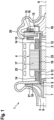
- the fluid flow machine 1 shown comprises a shaft 2 in which a compressor wheel 3 is arranged at one end and a turbine wheel 19 at the other end.
- the shaft 2 is rotated by means of an electric motor 4 in a rotational movement about its longitudinal axis A.
- the electric motor 4 comprises a winding 17 arranged around the shaft 2 and a permanent magnet 23 accommodated in the shaft 2. So that the shaft 2 can execute a rotary movement, it is rotatably mounted via two radial bearings 14.
- two axial bearings 15 are provided in the area of an axial bearing disk 18 connected to the shaft 2.
- the bearings 14, 15 are integrated in a motor housing 22 of the electric motor 4.
- the compressor wheel 3 is surrounded by a compressor housing 21 and the turbine wheel 19 is surrounded by a turbine housing 20.
- the compressor wheel 3 of the turbomachine 1 shown has several air ducts 7, 8 in a hub section 5, which is inserted into a hollow cylindrical shaft section 6.
- the air ducts 7, 8 connect the compressor inlet 9 with an annular space 10 on the side of the compressor wheel 3 facing away from the compressor inlet 9. This creates a
- Partial air flow from the compressor inlet 9 is fed into the annular space 10 so that the same air pressure prevails in both spaces. This means that the axial forces acting on the compressor wheel 3 cancel each other out. The bearing losses in the area of the axial bearings 15 are reduced accordingly.
- the shaft section 6 Since in the present case the radially extending air channels 8 are arranged in the region of the hub section 5 which is inserted into the hollow cylindrical shaft section 6, the shaft section 6 has air channels 11 arranged in overlap with the air channels 8.
- the turbomachine 1 shown has further air ducts 12,13.
- the air ducts 12,13 connect the annular space 10 with at least one bearing 14,15.
- at least one axially extending air duct 12 leads from the annular space 10 via the radial bearings 14 from the compressor side to the turbine side of the Turbomachine 1, so that the radial bearings 14 are cooled by the air supplied.
- the at least one air duct 12 is guided over an annular gap 16 between the winding 17 and the shaft 2, so that the electric motor 4 is also cooled.
- the at least one air duct 12 is connected to at least one radially extending air duct 13, which extends through the axial bearing disk 18 from radially inside to radially outside. This not only cools the axial bearings 15, but also increases the air pressure to the level in front of the turbine wheel 19.
- the air flow 24 leading through the air ducts 7, 8, 12, 13 is in the Fig.2 indicated by arrows.
Landscapes
- Engineering & Computer Science (AREA)
- Mechanical Engineering (AREA)
- General Engineering & Computer Science (AREA)
- Physics & Mathematics (AREA)
- Fluid Mechanics (AREA)
- Chemical & Material Sciences (AREA)
- Thermal Sciences (AREA)
- Combustion & Propulsion (AREA)
- Power Engineering (AREA)
- Chemical Kinetics & Catalysis (AREA)
- General Chemical & Material Sciences (AREA)
- Structures Of Non-Positive Displacement Pumps (AREA)
- Fuel Cell (AREA)
Description
- Die Erfindung betrifft eine Strömungsmaschine mit den Merkmalen des Oberbegriffs des Anspruchs 1. Die Strömungsmaschine kann insbesondere zur Luftversorgung von Brennstoffzellensystemen eingesetzt werden. Darüber hinaus betrifft die Erfindung ein Verfahren zum Betreiben einer derartigen Strömungsmaschine.
- Brennstoffzellensysteme benötigen Sauerstoff, der in einer Brennstoffzelle des Systems mit Wasserstoff zu Wasser bzw. Wasserdampf reagiert. Auf diese Weise wird durch elektrochemische Wandlung eine elektrische Leistung erzeugt, die als Antriebsenergie, beispielsweise zum Antrieb eines Fahrzeugs, genutzt werden kann. Als Sauerstoffquelle dient üblicherweise Umgebungsluft, die der Brennstoffzelle mittels eines Luftverdichtungssystems zugeführt wird, da der Prozess einen bestimmten Luftmassenstrom und ein bestimmtes Druckniveau erfordert. Das Luftverdichtungssystem umfasst eine hochdrehende Strömungsmaschine mit mindestens einem auf einer Welle angeordneten Verdichterrad, das elektromotorisch angetrieben wird. Zur Energierückgewinnung kann auf der Welle ein Turbinenrad angeordnet sein, der Brennstoffzellenabluft zugeführt wird. In diesem Fall handelt es sich bei der Strömungsmaschine um einen Abgasturbolader mit einem zusätzlichen Elektromotor.
- Die maximale Drehzahl des zusätzlichen Elektromotors ist aus regelungstechnischen und Festigkeitsgründen beschränkt, beispielsweise auf ein Maximum zwischen 100.000 und 125.000 1/min. Abgasturbolader ohne zusätzlichen Elektromotorerreichen Drehzahlen zwischen 180.000 und 250.000 1/min. Der erreichbare Verdichterauslassdruck bei einer Strömungsmaschine ist proportional zum Quadrat der Umfangsgeschwindigkeit am Außendurchmesser des Verdichterrads. Das heißt, dass er durch die Drehzahl und den Außendurchmesser des Verdichterrads bestimmt wird. Aufgrund der für das Brennstoffzellensystem notwenigen Drücke ergeben sich in Verbindung mit der genannten Drehzahlbeschränkung Verdichterräder mit vergleichsweise großen Außendurchmessern. Diese erzeugen große Axialkräfte in Richtung des Verdichtereinlasses, da sich im Betrieb der am Verdichterauslass herrschende Druck auf den Radrücken des Verdichterrads aufprägt. Die hohen Axialkräfte wiederum erfordern entsprechend große Axiallager. Mit der Größe der Axiallager steigt jedoch die Verlustleistung, wobei die Axiallager einen deutlich größeren Anteil (2/3-Anteil) an den Gesamtlagerverlusten als die Radiallager (1/3-Anteil) haben.
- Strömungsmaschinen, die der Luftversorgung von Brennstoffzellensysteme dienen, weisen in der Regel Folienluftlager auf, um das System ölfrei zu halten. Folienluftlager erzeugen jedoch Luftreibungsverluste und werden daher mit Hilfe von zusätzlicher Luft gekühlt. Hierzu werden üblicherweise etwa 5 bis 10 % der verdichteten Luft für die Kühlung abgezweigt. Diese abgezweigte Luftmenge steht anschließend für den Prozess in der Brennstoffzelle nicht mehr zur Verfügung und setzt somit den Wirkungsgrad der Strömungsmaschine herab. Damit die abgezweigte Luft überhaupt Kühlleistung erbringen kann, wird sie zuvor selber gekühlt. In der Regel wird hierzu die Kühlluft hinter einem Ladeluftkühler des Brennstoffzellensystems abgezweigt. Der zusätzliche Kühlbedarf muss bei der Auslegung des Ladeluftkühlers berücksichtigt werden. Zudem muss eine zusätzliche Leitung vorgesehen werden, mittels welches die Kühlluft der Strömungsmaschine zugeführt werden kann.
- Strömungsmaschinen für Energiewandler, insbesondere für Brennstoffzellen, mit einem Verdichter zum Verdichten von dem Energiewandler zuzuführender Luft werden in den Dokumenten
DE 10 2015 007 379 A1 undDE 10 2014 018 096 A1 beschrieben. - Ausgehend von dem vorstehend genannten Stand der Technik liegt der vorliegenden Erfindung die Aufgabe zugrunde, den Wirkungsgrad einer Strömungsmaschine zur Luftversorgung eines Brennstoffzellensystems zu verbessern.
- Zur Lösung der Aufgabe werden die Strömungsmaschine mit den Merkmalen des Anspruchs 1 sowie das Verfahren mit den Merkmalen des Anspruchs 9 vorgeschlagen. Vorteilhafte Weiterbildungen der Erfindung sind den jeweiligen Unteransprüchen zu entnehmen.
- Die zur Luftversorgung eines Brennstoffzellensystems vorgeschlagene Strömungsmaschine umfasst mindestens ein mit einer Welle drehfest verbundenes Verdichterrad sowie einen Elektromotor zum Antreiben der Welle, wobei das Verdichterrad über einen Nabenabschnitt mit einem vorzugsweise hohlzylinderförmigen Wellenabschnitt der Welle drehfest verbunden ist. Erfindungsgemäß ist im Nabenabschnitt mindestens ein Luftkanal ausgebildet, über den ein Verdichtereinlass mit einem Ringraum auf der dem Verdichtereinlass abgewandten Seite des Verdichterrads verbunden ist, so dass auf beiden Seiten des Verdichterrads im Wesentlichen der gleiche Luftdruck anliegt. Folglich wirken auf das Verdichterrad Axialkräfte, die sich vollständig oder nahezu vollständig gegeneinander aufheben. Das heißt, dass ein Axialkraftausgleich bewirkt wird. Dies wiederum hat zur Folge, dass die Verlustleistung in den Axiallagern verringert werden kann. Ferner verringert sich der Kühlluftbedarf in den Lagern. Beides führt im Ergebnis zu einer Wirkungsgradsteigerung. Darüber hinaus erhöht sich die Robustheit der Strömungsmaschine gegenüber äußeren Beschleunigungen, beispielsweise bei einer Schlechtweg-Fahrt, sofern die Strömungsmaschine in einem Fahrzeug zum Einsatz gelangt.
- Der Ringraum auf der dem Verdichtereinlass abgewandten Seite des Verdichterrads ist über mindestens einen weiteren Luftkanal mit mindestens einem Lager der Welle verbunden. Die über den mindestens einen weiteren Luftkanal zugeführte Luft kann zur Kühlung des mindestens einen Lagers eingesetzt werden. Der mindestens eine weitere Luftkanal zur Anbindung mindestens eines Wellenlagers an den Ringraum und damit an die Verdichtereinlassseite ist ferner über einen Ringspalt zwischen der Welle und einer die Welle umgebenden Wicklung des Elektromotors geführt. Dadurch kann die über den mindestens einen weiteren Luftkanal zugeführte Luft zur Kühlung des Elektromotors genutzt werden.
- Bevorzugt weist der Nabenabschnitt mindestens einen axial verlaufenden Luftkanal auf. Das heißt, dass der mindestens eine Luftkanal parallel zu einer Längsachse der Welle verläuft. Der Luftkanal kann beispielsweise als Axialbohrung ausgeführt sein. Sofern nur ein axial verlaufender Luftkanal vorgesehen ist, ist dieser bevorzugt zentral bzw. koaxial zur Längsachse der Welle angeordnet. Der mindestens eine axial verlaufende Luftkanal steht vorzugsweise in direkter Verbindung mit der Verdichtereinlassseite, so dass ein Teilstrom der dem Verdichterrad zugeführten Luft über den mindestens einen axial verlaufenden Luftkanal abgezweigt und auf die Rückseite des Verdichterrads geführt wird.
- Des Weiteren bevorzugt weist der Nabenabschnitt mindestens einen im Wesentlichen radial verlaufenden Luftkanal auf. Über den mindestens einen im Wesentlichen radial verlaufenden Luftkanal kann eine Verbindung des mindestens einen axial verlaufenden Luftkanals mit dem Ringraum auf der Rückseite des Verdichterrads hergestellt werden. Der im Wesentlichen radial verlaufende Luftkanal kann beispielsweise durch eine Radialbohrung im Nabenabschnitt ausgebildet werden. Bevorzugt weist der Nabenabschnitt mehrere im Wesentlichen radial verlaufende Luftkanäle auf, die im gleichen Winkelabstand zueinander angeordnet sind. Die hinter das Verdichterrad geführte Luft wird somit gleichmäßig im Ringraum verteilt.
- Vorteilhafterweise ist der Nabenabschnitt zumindest abschnittsweise in den hohlzylinderförmigen Wellenabschnitt eingesetzt, insbesondere eingepresst. Das Ineinandergreifen der Abschnitte erhöht die Steifigkeit und damit die Stabilität des Verbunds.
- Ferner wird vorgeschlagen, dass der hohlzylinderförmige Wellenabschnitt mindestens einen im Wesentlichen radial verlaufenden Luftkanal aufweist, der in Überdeckung mit dem mindestens einen radial verlaufenden Luftkanal des Nabenabschnitts angeordnet ist. Der mindestens eine im Wesentlichen radial verlaufende Luftkanal des Nabenabschnitts kann demnach in einem Bereich angeordnet sein, der in den hohlzylinderförmigen Wellenabschnitt eingesetzt, insbesondere eingepresst ist. Auf diese Weise wird eine in axialer Richtung kompakt bauende Strömungsmaschine geschaffen.
- Vorzugsweise ist das mindestens eine Lager als Folienluftlager ausgeführt, so dass die Ölfreiheit des Systems gewährleistet ist.
- Ergänzend wird vorgeschlagen, dass der mindestens eine weitere Luftkanal durch eine drehfest mit der Welle verbundene, innenbelüftete Axiallagerscheibe zur Lagerung eines Turbinenrads geführt ist. Neben einer Kühlung des Axiallagers kann somit zugleich ein Druckhub erzielt werden. Denn mit Hilfe der innenbelüfteten Axiallagerscheibe kann der Luftdruck der über den mindestens einen weiteren Luftkanal zugeführten Luft auf das Niveau vor dem Turbinenrad angehoben werden.
- Über den Verdichtereinlass wird Luft aus der Umgebung angesaugt. Die angesaugte Luft hat somit Umgebungstemperatur und damit ein sehr niedriges Temperaturniveau. Damit kann die Rotor- und Lagerkühlfunktion in der Regel bereitsoptimal erfüllt werden.
- Bei Bedarf kann den Luftkanälen aber auch gekühlte Umgebungsluft zugeführt werden, das heißt Luft, die vorab selbst gekühlt wurde. Gemäß einer bevorzugten Ausführungsform der Erfindung sind daher sämtliche Luftkanäle, welche den Verdichtereinlass mit dem rückwärtigen Ringraum und ggf. mindestens einem Wellenlager verbinden, mit gekühlter oder ungekühlter Umgebungsluft beaufschlagbar.
- Über die innenbelüftete Axiallagerscheibe kann der Luftdruck der gekühlten oder ungekühlten Umgebungsluft auf das Niveau vor dem Turbinenrad angehoben werden, so dass zumindest ein Teil der für die Kühlluftförderung erforderlichen Energie mit Hilfe der Turbine zurückgewonnen wird.
- Eine Abwandlung besteht darin, auf den Druckhub durch die innenbelüftete Axiallagerscheibe zu verzichten und die Umgebungsluft hinter dem Turbinenauslass in das System zurückzuführen.
- Zur Lösung der eingangs genannten Aufgabe wird darüber hinaus ein Verfahren zum Betreiben einer erfindungsgemäßen Strömungsmaschine vorgeschlagen. Bei dem Verfahren werden zumindest die Luftkanäle, welche den Verdichtereinlass mit dem rückwärtigen Ringraum verbinden, mit gekühlter oder ungekühlter Umgebungsluft beaufschlagt. Vorteilhafterweise ist der Ringraum über mindestens einen weiteren Luftkanal mit mindestens einem Lager verbunden, so dass die Umgebungsluft dem mindestens einen Lager zugeführt wird. Auf diese Weise kann das mindestens eine Lager mit Hilfe der Umgebungsluft gekühlt werden.
- Des Weiteren wird vorgeschlagen, dass bei der Durchführung des Verfahrens mit Hilfe einer innenbelüfteten Axiallagerscheibe, durch die mindestens ein Luftkanal geführt ist, der Kühlluftdruck angehoben wird. Auf diese Weise kann zumindest ein Teil der für die Förderung der Umgebungsluft erforderlichen Energie zurückgewonnen werden.
- Die Erfindung wird nachfolgend anhand der beiliegenden Zeichnungen näher erläutert. Diese zeigen:
-
Fig. 1 einen schematischen Längsschnitt durch eine erfindungsgemäße Strömungsmaschine und -
Fig. 2 einen schematischen Längsschnitt durch die Strömungsmaschine derFig. 1 mit einer Darstellung der Luftführung. - Die in der
Fig. 1 dargestellte Strömungsmaschine 1 umfasst eine Welle 2, in der einenends ein Verdichterrad 3 und andernends ein Turbinenrad 19 angeordnet ist. Die Welle 2 wird mit Hilfe eines Elektromotors 4 in einer Drehbewegung um ihre Längsachse A angetrieben. Der Elektromotor 4 umfasst hierzu eine um die Welle 2 herum angeordnete Wicklung 17 und einen in der Welle 2 aufgenommenen Permanentmagneten 23. Damit die Welle 2 eine Drehbewegung ausführen kann, ist sie über zwei Radiallager 14 drehbar gelagert. Ferner sind zwei Axiallager 15 im Bereich einer mit der Welle 2 verbundenen Axiallagerscheibe 18 vorgesehen. Die Lager 14, 15 sind in ein Motorgehäuse 22 des Elektromotors 4 integriert. Das Verdichterrad 3 ist von einem Verdichtergehäuse 21 und das Turbinenrad 19 ist von einem Turbinengehäuse 20 umgeben. - Im Betrieb der Strömungsmaschine 1 wird das Verdichterrad 3 über einen Verdichtereinlass 9 von Luft angeströmt. Um die dabei auf das Verdichterrad 3 wirkenden Axialkräfte zu minimieren, weist das Verdichterrad 3 der dargestellten Strömungsmaschine 1 in einem Nabenabschnitt 5, der in einen hohlzylinderförmigen Wellenabschnitt 6 eingesetzt ist, mehrere Luftkanäle 7, 8 auf. Die Luftkanäle 7, 8 verbinden den Verdichtereinlass 9 mit einem Ringraum 10 auf der dem Verdichtereinlass 9 abgewandten Seite des Verdichterrads 3. Somit wird ein
- Teilstrom der Luft aus dem Verdichtereinlass 9 dem Ringraum 10 zugeführt, so dass in beiden Räumen der gleiche Luftdruck herrscht. Dies hat zur Folge, dass sich die auf das Verdichterrad 3 wirkenden Axialkräfte gegenseitig aufheben. Entsprechend verringern sich die Lagerverluste im Bereich der Axiallager 15.
- Da vorliegend die radial verlaufenden Luftkanäle 8 im Bereich des Nabenabschnitts 5 angeordnet sind, der in den hohlzylinderförmigen Wellenabschnitt 6 eingesetzt ist, weist der Wellenabschnitt 6 in Überdeckung mit den Luftkanälen 8 angeordnete Luftkanäle 11 auf.
- Wie ferner der
Fig. 2 zu entnehmen ist, weist die dargestellte Strömungsmaschine 1 weitere Luftkanäle 12,13 auf. Die Luftkanäle 12,13 verbinden den Ringraum 10 mit mindestens einem Lager 14,15. Vorliegend führt mindestens ein axial verlaufender Luftkanal 12 vom Ringraum 10 über die Radiallager 14 von der Verdichterseite auf die Turbinenseite der Strömungsmaschine 1, so dass über die zugeführte Luft eine Kühlung der Radiallager 14 bewirkt wird. Der mindestens eine Luftkanal 12 ist dabei über einen Ringspalt 16 zwischen der Wicklung 17 und der Welle 2 geführt, so dass auch eine Kühlung des Elektromotors 4 erreicht wird. Am turbinenseitigen Ende der Welle 2 ist der mindestens eine Luftkanal 12 mit mindestens einem radial verlaufenden Luftkanal 13 verbunden, der sich durch die Axiallagerscheibe 18 von radial innen nach radial außen erstreckt. Somit wird nicht nur eine Kühlung der Axiallager 15 erreicht, sondern ferner eine Anhebung des Luftdrucks auf das Niveau vor dem Turbinenrad 19. Der über die Luftkanäle 7, 8, 12,13 führende Luftstrom 24 ist in derFig. 2 durch Pfeile angedeutet.
Claims (10)
- Strömungsmaschine (1) zur Luftversorgung eines Brennstoffzellensystems, umfassend mindestens ein mit einer Welle (2) drehfest verbundenes Verdichterrad (3) sowie einen Elektromotor (4) zum Antreiben der Welle (2), wobei das Verdichterrad (3) über einen Nabenabschnitt (5) mit einem vorzugsweise hohlzylinderförmigen Wellenabschnitt (6) der Welle (2) drehfest verbunden ist,wobei im Nabenabschnitt (5) mindestens ein Luftkanal (7, 8) ausgebildet ist, über den ein Verdichtereinlass (9) mit einem Ringraum (10) auf der dem Verdichtereinlass (9) abgewandten Seite des Verdichterrads (3) verbunden ist
dadurch gekennzeichnet, dass der Ringraum (10) auf der dem Verdichtereinlass (9) abgewandten Seite des Verdichterrads (3) über mindestens einen weiteren Luftkanal (12, 13) mit mindestens einem Lager (14,15) der Welle (2) verbunden ist, wobei der mindestens eine weitere Luftkanal (12) über einen Ringspalt (16) zwischen der Welle (2) und einer die Welle (2) umgebenden Wicklung (17) des Elektromotors (3) geführt ist. - Strömungsmaschine (1) nach Anspruch 1,
dadurch gekennzeichnet, dass der Nabenabschnitt (5) mindestens einen axial verlaufenden Luftkanal (7) aufweist. - Strömungsmaschine (1) nach Anspruch 1 oder 2,
dadurch gekennzeichnet, dass der Nabenabschnitt (5) mindestens einen im Wesentlichen radial verlaufenden Luftkanal (8) aufweist. - Strömungsmaschine (1) nach einem der vorhergehenden Ansprüche, dadurch gekennzeichnet, dass der Nabenabschnitt (5) zumindest abschnittsweise in den hohlzylinderförmigen Wellenabschnitt (6) eingesetzt, insbesondere eingepresst ist.
- Strömungsmaschine (1) nach Anspruch 3 oder 4,
dadurch gekennzeichnet, dass der hohlzylinderförmige Wellenabschnitt (6) mindestens einen im Wesentlichen radial verlaufenden Luftkanal (11) aufweist, der in Überdeckung mit dem mindestens einen radial verlaufenden Luftkanal (8) des Nabenabschnitts (5) angeordnet ist. - Strömungsmaschine (1) nach einem der vorhergehenden Ansprüche, dadurch gekennzeichnet, dass das mindestens eine Lager (14, 15) als Folienluftlager ausgeführt ist.
- Strömungsmaschine (1) nach einem der vorhergehenden Ansprüche,
dadurch gekennzeichnet, dass der mindestens eine weitere Luftkanal (13) durch eine drehfest mit der Welle (2) verbundene, innenbelüftete Axiallagerscheibe (18) zur Lagerung eines Turbinenrads (19) geführt ist. - Strömungsmaschine (1) nach einem der vorhergehenden Ansprüche,
dadurch gekennzeichnet, dass die Luftkanäle (7, 8, 12,13) zur Verbindung des Verdichtereinlasses (9) mit gekühlter oder ungekühlter Umgebungsluft beaufschlagbar sind. - Verfahren zum Betreiben einer Strömungsmaschine (1) nach einem der vorhergehenden Ansprüche,
dadurch gekennzeichnet, dass die Luftkanäle (7, 8, 12,13) mit gekühlter oder ungekühlter Umgebungsluft beaufschlagt werden. - Verfahren nach Anspruch 9,
dadurch gekennzeichnet, dass mit Hilfe einer innenbelüfteten Axiallagerscheibe (18), durch die mindestens ein Luftkanal (13) geführt ist, der Kühlluftdruck angehoben wird.
Applications Claiming Priority (2)
| Application Number | Priority Date | Filing Date | Title |
|---|---|---|---|
| DE102019215337.2A DE102019215337A1 (de) | 2019-10-07 | 2019-10-07 | Strömungsmaschine, Verfahren zum Betreiben einer Strömungsmaschine |
| PCT/EP2020/073980 WO2021069143A1 (de) | 2019-10-07 | 2020-08-27 | Strömungsmaschine, verfahren zum betreiben einer strömungsmaschine |
Publications (2)
| Publication Number | Publication Date |
|---|---|
| EP4041994A1 EP4041994A1 (de) | 2022-08-17 |
| EP4041994B1 true EP4041994B1 (de) | 2024-08-14 |
Family
ID=72340334
Family Applications (1)
| Application Number | Title | Priority Date | Filing Date |
|---|---|---|---|
| EP20765235.5A Active EP4041994B1 (de) | 2019-10-07 | 2020-08-27 | Strömungsmaschine zur luftversorgung eines brennstoffzellensystems, verfahren zum betreiben einer solchen strömungsmaschine |
Country Status (7)
| Country | Link |
|---|---|
| US (1) | US20240093695A1 (de) |
| EP (1) | EP4041994B1 (de) |
| JP (1) | JP7387886B2 (de) |
| KR (1) | KR20220071972A (de) |
| CN (1) | CN114556754A (de) |
| DE (1) | DE102019215337A1 (de) |
| WO (1) | WO2021069143A1 (de) |
Families Citing this family (2)
| Publication number | Priority date | Publication date | Assignee | Title |
|---|---|---|---|---|
| JP2023174295A (ja) * | 2022-05-27 | 2023-12-07 | 株式会社豊田自動織機 | 遠心圧縮機 |
| DE102022114460A1 (de) * | 2022-06-09 | 2023-12-14 | Zf Cv Systems Global Gmbh | Verdichter für ein Brennstoffzellensystem, und Brennstoffzellensystem mit selbigem |
Family Cites Families (8)
| Publication number | Priority date | Publication date | Assignee | Title |
|---|---|---|---|---|
| EP2102507B1 (de) * | 2007-01-19 | 2010-08-18 | Daimler AG | Strömungsarbeitsmaschine |
| DE102014018096A1 (de) * | 2014-12-09 | 2015-07-02 | Daimler Ag | Strömungsmaschine für einen Energiewandler, insbesondere eine Brennstoffzelle |
| DE102014018070A1 (de) * | 2014-12-09 | 2015-07-02 | Daimler Ag | Lagereinrichtung zum Lagern eines Rotors einer Strömungsmaschine |
| DE102015007379A1 (de) * | 2015-06-10 | 2016-01-21 | Daimler Ag | Strömungsmaschine für einen Energiewandler, insbesondere eine Brennstoffzelle |
| DE102017211940A1 (de) * | 2017-07-12 | 2019-01-17 | Bayerische Motoren Werke Aktiengesellschaft | Brennstoffzellensystem für ein Kraftfahrzeug sowie Strömungsmaschine für ein Brennstoffzellensystem |
| DE102017216763A1 (de) * | 2017-09-21 | 2019-03-21 | Bayerische Motoren Werke Aktiengesellschaft | Verfahren zum Betrieb einer Strömungsmaschine sowie Strömungsmaschine |
| WO2019087970A1 (ja) | 2017-11-01 | 2019-05-09 | 株式会社Ihi | 遠心圧縮機 |
| US11131313B2 (en) * | 2019-05-10 | 2021-09-28 | Garrett Transportation I Inc | Single-stage compressor with bleed system for thrust load alleviation |
-
2019
- 2019-10-07 DE DE102019215337.2A patent/DE102019215337A1/de active Pending
-
2020
- 2020-08-27 US US17/766,901 patent/US20240093695A1/en active Pending
- 2020-08-27 CN CN202080070470.9A patent/CN114556754A/zh active Pending
- 2020-08-27 JP JP2022520630A patent/JP7387886B2/ja active Active
- 2020-08-27 EP EP20765235.5A patent/EP4041994B1/de active Active
- 2020-08-27 WO PCT/EP2020/073980 patent/WO2021069143A1/de active Application Filing
- 2020-08-27 KR KR1020227014822A patent/KR20220071972A/ko unknown
Also Published As
| Publication number | Publication date |
|---|---|
| DE102019215337A1 (de) | 2021-04-08 |
| KR20220071972A (ko) | 2022-05-31 |
| WO2021069143A1 (de) | 2021-04-15 |
| CN114556754A (zh) | 2022-05-27 |
| JP2022550594A (ja) | 2022-12-02 |
| US20240093695A1 (en) | 2024-03-21 |
| JP7387886B2 (ja) | 2023-11-28 |
| EP4041994A1 (de) | 2022-08-17 |
Similar Documents
| Publication | Publication Date | Title |
|---|---|---|
| EP2600007B1 (de) | Kraftfahrzeugsystemeinrichtung sowie Verfahren zum Betreiben einer Kraftfahrzeugsystemeinrichtung | |
| DE102012013048A1 (de) | Strömungsmaschine für einen Energiewandler sowie Brennstoffzelleneinrichtung mit einer solchen Strömungsmaschine | |
| DE602005000116T2 (de) | Strahltriebwerks-Architektur mit zwei Fans an der Vorderseite | |
| EP4041994B1 (de) | Strömungsmaschine zur luftversorgung eines brennstoffzellensystems, verfahren zum betreiben einer solchen strömungsmaschine | |
| EP2600015B1 (de) | Turboverdichter, Brennstoffzellensystem | |
| WO2019020289A1 (de) | Turbomaschine, insbesondere für ein brennstoffzellensystem | |
| EP2785977A2 (de) | Aufladeeinrichtung für eine brennstoffzelle, insbesondere eines kraftwagens | |
| DE102010035725A1 (de) | Aufladeeinrichtung für eine Energieumwandlungseinrichtung | |
| DE102020205172A1 (de) | Strömungsmaschine, Verfahren zum Betreiben einer Strömungsmaschine | |
| WO2016091348A1 (de) | Strömungsmaschine für einen energiewandler, insbesondere eine brennstoffzelle | |
| DE102012221303A1 (de) | Antriebseinrichtung mit einer Brennstoffzelle und einem Abgasturbolader | |
| WO2021063600A1 (de) | Axial-gaslager | |
| WO2011113465A1 (de) | Aufladeeinrichtung für eine brennstoffzelle | |
| WO2021018455A1 (de) | Luftzuführvorrichtung | |
| DE102021202889A1 (de) | Gaszuführvorrichtung mit einer durch eine Gaslageranordnung gelagerten Welle | |
| WO2021063566A1 (de) | Axial-gaslager | |
| WO2000029721A1 (de) | Strömungsmaschine, insbesondere turbosatz mit einer strömungsmaschine und mit einer elektrischen maschine | |
| WO2019020288A1 (de) | Turbomaschine, insbesondere für ein brennstoffzellensystem | |
| WO2019020287A1 (de) | Turbomaschine, insbesondere für ein brennstoffzellensystem | |
| DE102011003509A1 (de) | Fliehkraftunterdruckpumpe und Verfahren zur Unterdruckerzeugung | |
| WO2023083588A1 (de) | Radialverdichter und verfahren zum betreiben eines radialverdichters | |
| DE102021205472A1 (de) | Elektrisch angetriebener Luftverdichter | |
| DE102022206534A1 (de) | Gasfördervorrichtung | |
| DE202022104248U1 (de) | Aufladevorrichtung mit Axiallager | |
| DE102018204619A1 (de) | Strömungsmaschine, insbesondere Verdichtereinrichtung |
Legal Events
| Date | Code | Title | Description |
|---|---|---|---|
| STAA | Information on the status of an ep patent application or granted ep patent |
Free format text: STATUS: UNKNOWN |
|
| STAA | Information on the status of an ep patent application or granted ep patent |
Free format text: STATUS: THE INTERNATIONAL PUBLICATION HAS BEEN MADE |
|
| PUAI | Public reference made under article 153(3) epc to a published international application that has entered the european phase |
Free format text: ORIGINAL CODE: 0009012 |
|
| STAA | Information on the status of an ep patent application or granted ep patent |
Free format text: STATUS: REQUEST FOR EXAMINATION WAS MADE |
|
| 17P | Request for examination filed |
Effective date: 20220509 |
|
| AK | Designated contracting states |
Kind code of ref document: A1 Designated state(s): AL AT BE BG CH CY CZ DE DK EE ES FI FR GB GR HR HU IE IS IT LI LT LU LV MC MK MT NL NO PL PT RO RS SE SI SK SM TR |
|
| DAV | Request for validation of the european patent (deleted) | ||
| DAX | Request for extension of the european patent (deleted) | ||
| STAA | Information on the status of an ep patent application or granted ep patent |
Free format text: STATUS: EXAMINATION IS IN PROGRESS |
|
| 17Q | First examination report despatched |
Effective date: 20230620 |
|
| GRAP | Despatch of communication of intention to grant a patent |
Free format text: ORIGINAL CODE: EPIDOSNIGR1 |
|
| STAA | Information on the status of an ep patent application or granted ep patent |
Free format text: STATUS: GRANT OF PATENT IS INTENDED |
|
| INTG | Intention to grant announced |
Effective date: 20240419 |
|
| GRAS | Grant fee paid |
Free format text: ORIGINAL CODE: EPIDOSNIGR3 |
|
| GRAA | (expected) grant |
Free format text: ORIGINAL CODE: 0009210 |
|
| STAA | Information on the status of an ep patent application or granted ep patent |
Free format text: STATUS: THE PATENT HAS BEEN GRANTED |
|
| AK | Designated contracting states |
Kind code of ref document: B1 Designated state(s): AL AT BE BG CH CY CZ DE DK EE ES FI FR GB GR HR HU IE IS IT LI LT LU LV MC MK MT NL NO PL PT RO RS SE SI SK SM TR |
|
| REG | Reference to a national code |
Ref country code: GB Ref legal event code: FG4D Free format text: NOT ENGLISH |
|
| REG | Reference to a national code |
Ref country code: CH Ref legal event code: EP |
|
| REG | Reference to a national code |
Ref country code: DE Ref legal event code: R096 Ref document number: 502020008882 Country of ref document: DE |
|
| REG | Reference to a national code |
Ref country code: IE Ref legal event code: FG4D Free format text: LANGUAGE OF EP DOCUMENT: GERMAN |