EP4041602B1 - Aufblasbare airbaganordnungen für eine mit einer versorgungskomponente ausgestattete fahrzeugsitzposition - Google Patents
Aufblasbare airbaganordnungen für eine mit einer versorgungskomponente ausgestattete fahrzeugsitzposition Download PDFInfo
- Publication number
- EP4041602B1 EP4041602B1 EP20799917.8A EP20799917A EP4041602B1 EP 4041602 B1 EP4041602 B1 EP 4041602B1 EP 20799917 A EP20799917 A EP 20799917A EP 4041602 B1 EP4041602 B1 EP 4041602B1
- Authority
- EP
- European Patent Office
- Prior art keywords
- seating position
- vehicle seating
- utility component
- inflatable airbag
- airbag
- Prior art date
- Legal status (The legal status is an assumption and is not a legal conclusion. Google has not performed a legal analysis and makes no representation as to the accuracy of the status listed.)
- Active
Links
Images


Classifications
-
- B—PERFORMING OPERATIONS; TRANSPORTING
- B60—VEHICLES IN GENERAL
- B60N—SEATS SPECIALLY ADAPTED FOR VEHICLES; VEHICLE PASSENGER ACCOMMODATION NOT OTHERWISE PROVIDED FOR
- B60N3/00—Arrangements or adaptations of other passenger fittings, not otherwise provided for
- B60N3/001—Arrangements or adaptations of other passenger fittings, not otherwise provided for of tables or trays
- B60N3/002—Arrangements or adaptations of other passenger fittings, not otherwise provided for of tables or trays of trays
-
- B—PERFORMING OPERATIONS; TRANSPORTING
- B60—VEHICLES IN GENERAL
- B60R—VEHICLES, VEHICLE FITTINGS, OR VEHICLE PARTS, NOT OTHERWISE PROVIDED FOR
- B60R21/00—Arrangements or fittings on vehicles for protecting or preventing injuries to occupants or pedestrians in case of accidents or other traffic risks
- B60R21/02—Occupant safety arrangements or fittings, e.g. crash pads
- B60R21/16—Inflatable occupant restraints or confinements designed to inflate upon impact or impending impact, e.g. air bags
- B60R21/20—Arrangements for storing inflatable members in their non-use or deflated condition; Arrangement or mounting of air bag modules or components
- B60R21/207—Arrangements for storing inflatable members in their non-use or deflated condition; Arrangement or mounting of air bag modules or components in vehicle seats
-
- B—PERFORMING OPERATIONS; TRANSPORTING
- B60—VEHICLES IN GENERAL
- B60R—VEHICLES, VEHICLE FITTINGS, OR VEHICLE PARTS, NOT OTHERWISE PROVIDED FOR
- B60R21/00—Arrangements or fittings on vehicles for protecting or preventing injuries to occupants or pedestrians in case of accidents or other traffic risks
- B60R21/02—Occupant safety arrangements or fittings, e.g. crash pads
- B60R21/16—Inflatable occupant restraints or confinements designed to inflate upon impact or impending impact, e.g. air bags
- B60R21/23—Inflatable members
- B60R21/231—Inflatable members characterised by their shape, construction or spatial configuration
- B60R21/2334—Expansion control features
- B60R21/2338—Tethers
-
- B—PERFORMING OPERATIONS; TRANSPORTING
- B60—VEHICLES IN GENERAL
- B60R—VEHICLES, VEHICLE FITTINGS, OR VEHICLE PARTS, NOT OTHERWISE PROVIDED FOR
- B60R21/00—Arrangements or fittings on vehicles for protecting or preventing injuries to occupants or pedestrians in case of accidents or other traffic risks
- B60R21/02—Occupant safety arrangements or fittings, e.g. crash pads
- B60R21/16—Inflatable occupant restraints or confinements designed to inflate upon impact or impending impact, e.g. air bags
- B60R21/26—Inflatable occupant restraints or confinements designed to inflate upon impact or impending impact, e.g. air bags characterised by the inflation fluid source or means to control inflation fluid flow
- B60R21/261—Inflatable occupant restraints or confinements designed to inflate upon impact or impending impact, e.g. air bags characterised by the inflation fluid source or means to control inflation fluid flow with means other than bag structure to diffuse or guide inflation fluid
- B60R21/262—Elongated tubular diffusers, e.g. curtain-type
-
- B—PERFORMING OPERATIONS; TRANSPORTING
- B60—VEHICLES IN GENERAL
- B60R—VEHICLES, VEHICLE FITTINGS, OR VEHICLE PARTS, NOT OTHERWISE PROVIDED FOR
- B60R21/00—Arrangements or fittings on vehicles for protecting or preventing injuries to occupants or pedestrians in case of accidents or other traffic risks
- B60R2021/003—Arrangements or fittings on vehicles for protecting or preventing injuries to occupants or pedestrians in case of accidents or other traffic risks characterised by occupant or pedestian
- B60R2021/0032—Position of passenger
-
- B—PERFORMING OPERATIONS; TRANSPORTING
- B60—VEHICLES IN GENERAL
- B60R—VEHICLES, VEHICLE FITTINGS, OR VEHICLE PARTS, NOT OTHERWISE PROVIDED FOR
- B60R21/00—Arrangements or fittings on vehicles for protecting or preventing injuries to occupants or pedestrians in case of accidents or other traffic risks
- B60R21/02—Occupant safety arrangements or fittings, e.g. crash pads
- B60R21/16—Inflatable occupant restraints or confinements designed to inflate upon impact or impending impact, e.g. air bags
- B60R21/23—Inflatable members
- B60R21/231—Inflatable members characterised by their shape, construction or spatial configuration
- B60R21/2334—Expansion control features
- B60R21/2338—Tethers
- B60R2021/23382—Internal tether means
-
- B—PERFORMING OPERATIONS; TRANSPORTING
- B60—VEHICLES IN GENERAL
- B60R—VEHICLES, VEHICLE FITTINGS, OR VEHICLE PARTS, NOT OTHERWISE PROVIDED FOR
- B60R21/00—Arrangements or fittings on vehicles for protecting or preventing injuries to occupants or pedestrians in case of accidents or other traffic risks
- B60R21/02—Occupant safety arrangements or fittings, e.g. crash pads
- B60R21/16—Inflatable occupant restraints or confinements designed to inflate upon impact or impending impact, e.g. air bags
- B60R21/20—Arrangements for storing inflatable members in their non-use or deflated condition; Arrangement or mounting of air bag modules or components
- B60R21/215—Arrangements for storing inflatable members in their non-use or deflated condition; Arrangement or mounting of air bag modules or components characterised by the covers for the inflatable member
-
- B—PERFORMING OPERATIONS; TRANSPORTING
- B60—VEHICLES IN GENERAL
- B60R—VEHICLES, VEHICLE FITTINGS, OR VEHICLE PARTS, NOT OTHERWISE PROVIDED FOR
- B60R21/00—Arrangements or fittings on vehicles for protecting or preventing injuries to occupants or pedestrians in case of accidents or other traffic risks
- B60R21/02—Occupant safety arrangements or fittings, e.g. crash pads
- B60R21/16—Inflatable occupant restraints or confinements designed to inflate upon impact or impending impact, e.g. air bags
- B60R21/23—Inflatable members
- B60R21/237—Inflatable members characterised by the way they are folded
Definitions
- the present disclosure relates generally to the field of automotive protective systems. More specifically, the present disclosure relates to an inflatable airbag assembly to deploy from a utility component disposed at a vehicle seating position.
- US2019/111877A1 discloses a vehicle seating position according to the preamble of claim 1.
- Airbag modules have been installed at various locations within a vehicle, including, but not limited to, in the steering wheel, in the dashboard and/or instrument panel, within the side doors or side seats, adjacent to a roof rail of the vehicle, in an overhead position, or at the knee or leg position.
- the terms “dashboard” and “instrument panel” refer to a region of a vehicle disposed forward of a motor vehicle occupant, and may include instrumentation, controls, a glove box, etc.
- opposite is a relational term used herein to refer to a placement of a particular feature or component corresponding to another related feature or component wherein the corresponding features are components are positionally juxtaposed to each other.
- a person's right hand is opposite the person's left hand.
- Inflatable airbag assemblies are widely used to reduce or minimize occupant injury during a collision event.
- An inflatable airbag cushion of an inflatable airbag assembly used in a vehicle should perform reliably, predictably, and in a repeatable manner.
- vehicle surfaces that may support or interact with an inflatable airbag cushion may vary from vehicle model to model, it is desirable that the inflatable airbag cushion be able to perform in a consistent, repeatable manner.
- inflatable airbag systems or assemblies are typically disposed at an interior of a housing in a packaged state (e.g., are rolled, folded, and/or otherwise compressed) or a compact configuration and may be retained in the packaged state behind a cover.
- a housing may be a component of an inflatable airbag assembly that contains at least a portion an inflatable airbag cushion of the inflatable airbag assembly.
- the housing may, in some instances, contain one or more of the inflatable airbag cushions (or a portion thereof), an inflator, inflator plumbing, sensors, and other components for the inflatable airbag assembly.
- the housing as used herein, comprises a door or closable aperture to secure in place those components disposed within the housing, at least until such time as the inflatable airbag cushion deploys.
- the door or closable aperture may open by virtue of force exerted against the door or closable aperture as the inflatable airbag cushion begins to inflate, or by an electrical/electronic mechanism to open the door or closable aperture.
- a housing may be a component provided by a manufacturer of an inflatable airbag assembly, or the housing may be a component provided by a manufacturer of a vehicle, or the function of a housing may be served by a structure of a vehicle that is to receive the inflatable airbag assembly.
- an inflator is initiated or otherwise triggered, which rapidly fills the airbag with inflation gas.
- the airbag can rapidly transition from a packaged state (e.g., a compact configuration) to a deployed state or an expanded configuration.
- the inflator may be triggered by an initiator that may be triggered by any suitable device or system, and the triggering may be in response to and/or influenced by one or more vehicle sensors.
- utility components such as a foldable/stowable writing surface or electronic display (or combination of such), etc.
- these utility components may be disposed forward of a vehicle seating position and interposed between the vehicle seating position and previously typical locations where an inflatable airbag system or assembly may be housed (e.g., at a dashboard/instrument panel).
- Mechanically interposed utility components may call for airbag assemblies that may be agnostic to, or particularly conformed to, such an interposed utility component.
- Some embodiments disclosed herein can provide improved positioning, cushioning, and/or safety to occupants involved in particular types of collisions.
- some embodiments can be configured to cushion a vehicle operator and/or front seat passengers seated adjacent to the passenger-side door.
- types of collisions in which certain embodiments may prove advantageous include one or more of (1) collisions where the struck object fails to engage the structural longitudinal components and/or engine block of the occupant's vehicle, (2) collisions wherein the impact forces act primarily outside of either the left or right longitudinal beams of the occupant's vehicle, (3) collisions classified under the Collision Deformation Classification scheme as FLEE or FREE, (4) front-impact collisions wherein the occupant's vehicle strikes no more than 25% of the vehicle width, (5) collisions as specified for the Insurance Institute for Highway Safety ("IIHS”) small overlap frontal crash test, or (6) collisions as specified for the National Highway Traffic Safety Administration (“NHTSA”) oblique impact test.
- IIHS Insurance Institute for Highway Safety
- NHLA National Highway Traffic Safety Administration
- the term "oblique" when used to describe a collision is intended to encompass any of the foregoing described collisions and any other collision in which an occupant's direction of travel as a result of the impact includes both a forward direction or component and a lateral direction or component.
- the longitudinal component of an occupant's post-collision trajectory during or after an oblique collision may be oriented in the vehicle-forward direction.
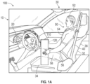
- FIG. 1A is a side view of a portion of a vehicle 10 having an inflatable airbag assembly 100, according to an embodiment of the present disclosure.
- the inflatable airbag assembly 100 (also referred to herein as simply airbag assembly) is in an undeployed state.
- An occupant 50 is shown occupying a seat 32 of a vehicle seating position 30.
- a head 52, a torso 54, a pelvic region 56, and thighs 58 and knees 59 of the occupant 50 are identified.
- the occupant 50 is restrained by a safety harness 40.
- the vehicle seating position 30 comprises the seat 32, a seat base 34, and a seatback 36.
- a dashboard/instrument panel (dashboard/IP) 20 is shown for reference.
- a footwell 22 is below the dashboard/IP 20 and forward of the vehicle seating position 30.
- a utility component 110 is disposed forward of at least a portion of the occupant 50 and the vehicle seating position 30, and aft of the dashboard/IP 20. In other words, the utility component 110 is disposed between the occupant 50 and the dashboard/IP 20. More particularly, the utility component 110 is partially disposed over the vehicle seating position 30.
- the utility component 110 may be stowable or adjustable, or both stowable and adjustable.
- the utility component of the present disclosure may be disposed at a vehicle seating position, and between a seat and another feature or component forward of the vehicle seating position, such as a dashboard/IP or another vehicle seating position.
- the utility component 110 may be coupled at or to the seat base 34 such that a portion of the utility component 110 is partially disposed over the vehicle seating position 30.
- the utility component 110 is constructed and mounted to withstand such energies and forces as may be produced during a collision event in any embodiment of the present disclosure.
- the utility component 110 may provide or otherwise comprise a housing 120 for the inflatable airbag assembly 100. More particularly, the utility component 110 may serve as the housing 120 for an inflatable airbag cushion (see, e.g., inflatable airbag cushion 130 in FIGS. 3 , 4 , et seq.).
- the housing 120 may be provided by a manufacturer of the inflatable airbag assembly 100 to be disposed within a portion of the utility component 110. In one embodiment, the housing 120 may be provided by a manufacturer of the vehicle 10 to receive the inflatable airbag assembly 100 and to dispose the inflatable airbag assembly 100 at the utility component 110.
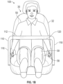
- FIG. 1B is a front view of the inflatable airbag assembly 100 of FIG. 1A , in an undeployed state.
- the occupant 50 and vehicle seating position 30 are shown for reference.
- the utility component 110 is disposed at least partially over the seat 32 and over at least a portion of the thighs 58 and/or knees 59 (hereafter, also thighs/knees 58, 59) of the occupant 50. At least a portion of the utility component 110 is disposed lateral to the thighs/knees 58, 59 of the occupant 50.
- the utility component 110 comprises a lateral member 112, a first support member 116, and a second support member 118.
- the lateral member 112 may serve as the housing 120 for the inflatable airbag assembly 100, or a distinct housing 120 may be coupled to or within the lateral member 112.
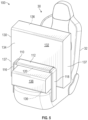
- FIG. 2 is a rear perspective view of the inflatable airbag assembly 100 of FIGS. 1A and 1B , with the inflatable airbag assembly 100 in an undeployed state.
- the seat 32, seat base 34 and seatback 36 of the vehicle seating position 30 are shown for reference.
- the lateral member 112 may comprise a work surface, an electronic display (e.g., a computer display), etc.
- a bottom surface of the lateral member 112 may comprise a cover that may open upon deployment of the inflatable airbag assembly 100.
- the lateral member 112 may have a greater longitudinal dimension (relative to the vehicle, see, e.g., the vehicle 10 in FIG. 1A ) than shown in order to support, e.g., a laptop computer, tablet computing device, writing tablet, etc., or to accommodate an incorporated electronic display.
- the utility component 110 may further comprise controls to allow an occupant (see, e.g., the occupant 50 in FIGS. 1A , 1B ) to interact with an incorporated electronic display, comfort controls for the particular vehicle seating position 30, etc.
- the lateral member 112 of the utility component 110 may comprise a display such as, e.g., a computer display, an entertainment system interface, etc.
- the lateral member 112 of the utility component 110 may comprise a folding display.
- the lateral member 112 of the utility component 110 may comprise a table or tray.
- the lateral member 112 of the utility component 110 may be tiltable toward the vehicle seating position 30.
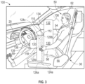
- FIG. 3 is a side view of the inflatable airbag assembly 100 of FIGS. 1A-1B and 2 , with the inflatable airbag assembly 100 in an at least partially deployed state.
- the vehicle seating position 30 is shown for reference, with the occupant 50 occupying the vehicle seating position 30.
- the inflatable airbag assembly 100 comprises an inflatable airbag cushion 130.
- the inflatable airbag cushion 130 is configured to deploy from the utility component 110.
- the inflatable airbag cushion 130 deploys initially downward (e.g., to exit the lateral member 112) and then rearward and upward.
- the inflatable airbag assembly 100 may comprise one or more sensors (not shown) to ensure that the inflatable airbag cushion 130 deploys only under appropriate conditions.
- the inflatable airbag assembly 100 may be configured to prevent deployment if a sensor indicates one or more the following conditions: the vehicle seating position 30 is not occupied by an occupant 50; the vehicle seating position 30 is occupied by an occupant 50 below a threshold weight; the utility component 110 is not secured in a particular position relative to the vehicle seating position 30; or a collision state does not exist.
- the inflatable airbag assembly 100 may be configured to prevent deployment if the utility component 110 is in a stowed configuration.
- the inflatable airbag assembly 100 may be configured to prevent deployment if the utility component 110 is not securely locked in a use position.
- the inflatable airbag cushion 130 is at least partially deployed, and at least partially inflated by action from an inflator 124a, 124b, or 124c (hereafter, generically referred to as "124x").
- the inflator 124x may be mounted at the vehicle seating position 30.
- the inflator 124a may be mounted at the seat base 34, for example, e.g., within, below, or adjacent the seat base 34.
- the inflator 124b may be disposed at or within either the first support member (see the first support member 116 in FIG. 2 ) or the second support member 118.
- the inflator 124b may be disposed at or within each of the first support member 116 and the second support member 118.
- the inflator 124c may be disposed within the housing 120, or within or at the lateral member 112.
- the inflatable airbag assembly 100 may comprise a plurality of inflators 124a, 124b, 124c.
- inflator 124x represents any inflator 124a, 124b, 124c of the foregoing embodiments.
- a tube 126a and/or 126b may be coupled to the inflator 124x and the inflatable airbag cushion 130. The tube 126a and/or 126b is configured to deliver inflation gas from the inflator 124x to the inflatable airbag cushion 130 during deployment.
- the inflator 124x may be activated as a result of a collision. Upon activation of the inflator 124x, inflation gas may be directed to the inflatable airbag cushion 130. Prior to inflation, the inflatable airbag cushion 130 may be rolled, folded, or otherwise disposed within the housing 120 (including in an embodiment wherein the lateral member 112 substantially constitutes the housing 120 and no distinct housing 120 is provided) in a compressed state. The inflatable airbag cushion 130 may comprise folds that unfold during deployment to deploy the inflatable airbag cushion 130 rearward and upward. In some embodiments, during inflation, inflation gas may be directed from the inflator 124x to the inflatable airbag cushion 130 via the tube 126a, 126b.
- the tube 126a may be routed from the inflator 124a through the seat base 34, then through either (or both) of the first support member 116 and the second support member 118, then through a portion of the lateral member 112 to the inflatable airbag cushion 130.
- the tube 126b may be routed from the inflator 124b through a portion of the first and/or second support member 116, 118, then through a portion of the lateral member 112 to the inflatable airbag cushion 130.
- the inflator 124c may be coupled directly to an inlet (not shown) of the inflatable airbag cushion 130, or may couple to the inflatable airbag cushion 130 via a short section of tube (not shown) routed from the inflator 124c to the inflatable airbag cushion 130.
- the inflatable airbag cushion 130 begins to inflate, whereby the housing 120 (including in an embodiment wherein the lateral member 112 substantially constitutes the housing 120 and no distinct housing 120 is provided) may be either triggered (e.g., by an electrical signal) or forced open and the inflatable airbag cushion 130 deploys in a downward trajectory and curves around the utility component 110 in a rearward and upward trajectory. More particularly, an upper region 132 of the inflatable airbag cushion 130 deploys downward from the housing 120, then curves rearward and upward to be positioned between the utility component 110 and the seat 32 of the vehicle seating position 30.
- the inflatable airbag cushion 130 in a deployed configuration, may be disposed between the utility component 110 and the seat base 34 of the vehicle seating position 30, and between the utility component 110 and the seatback 36 of the vehicle seating position 30.
- the inflatable airbag cushion 130 in a deployed configuration may be disposed between the utility component 110 and the occupant 50.
- a lower region 138 of the inflatable airbag cushion 130 deploys downward and turns to deploy so as to be below the lateral member 112 of the utility component 110 and somewhat forward. Furthermore, as the inflatable airbag cushion 130 begins to expand, the lower region 138 may conform to the thighs/knees 58, 59 of the occupant 50 to dispose a side portion 139 of the lower region 138 adjacent the thighs/knees 58, 59 and between the thighs/knees 58, 59 and first and second support members 116, 118. In a deployed configuration, the inflatable airbag cushion 130 extends vertically from below the utility component 110 to above the utility component 110.
- the inflatable airbag cushion 130 comprises a forward-facing panel 134 and an occupant-facing panel 136.
- the forward-facing panel 134 comprises a portion of the upper region 132 of the inflatable airbag cushion 130 facing forward relative to the vehicle, and may further comprise a portion of the lower region 138 of the inflatable airbag cushion 130 facing upward relative to the vehicle 10.
- the occupant-facing panel 136 comprises a rearward-facing (relative to the vehicle 10) portion of the upper region 132 and a downward-facing portion of the lower region 138 of the inflatable airbag cushion 130. In other words, the occupant-facing panel 136 of FIG.
- the occupant-facing panel 136 may receive or engage the head 52, torso 54, pelvic region 56, and thighs/knees 58, 59 of the occupant 50.
- the forward-facing panel 134 and the occupant-facing panel 136 may be formed of a single contiguous piece of appropriate material.
- the forward-facing panel 134 may couple to the occupant-facing panel 136 by one or more seams generally about a perimeter of the inflatable airbag cushion 130, or at seams disposed rearward or forward of a perimeter of the inflatable airbag cushion 130. Seams may be formed by sewing, radio-frequency (RF) welding, adhesive, or any other appropriate means.
- the inflatable airbag cushion 130 may comprise gas-permeable seams, vents, ports, apertures, etc. configured to enable energy absorption during a collision event, while also permitting post-collision deflation of the inflatable airbag cushion 130.
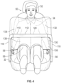
- FIG. 4 is a front view of the inflatable airbag assembly 100 of FIGS. 1A-1B and 2-3 , with the inflatable airbag cushion 130 at least partially deployed.
- the head 52, torso 54, pelvic region 56, and thighs/knees 58, 59 of the occupant 50, and the seat 32 are identified for reference.
- the first and second support members 116, 118 and lateral member 112 of the utility component 110 are shown.
- the inflatable airbag cushion 130 is at least partially inflated.
- the upper and lower regions 132, 138 of the inflatable airbag cushion 130, as well as the forward-facing panel 134, are shown.
- the inflatable airbag cushion 130 may be configured to deploy to receive and engage the head 52, torso 54, pelvic region 56, and thighs/knees 58, 59 of the occupant 50 during a collision event, and to dissipate collision energies of the occupant 50 to prevent or reduce injury to the occupant 50.
- the occupant 50 may be pushed, by collision energies, downward and forward, and may potentially "submarine" into the footwell 22, even if the occupant 50 is restrained by a harness (see the harness 40 in FIG. 1A ).
- the inflatable airbag assembly 100 of the present disclosure as the occupant 50 engages the inflatable airbag cushion 130, the inflatable airbag cushion 130 may conform in response to energies of impact of the occupant 50 on the inflatable airbag cushion 130.
- the inflatable airbag cushion 130 may be drawn somewhat forward and downward but is limited by the fixed position of the utility component 110, and the occupant 50 may be substantially protected from "submarining" forward and downward into the footwell 22.
- the occupant 50 may be forced upward and forward ("catapult” or “lift off"), potentially resulting in the occupant 50 colliding with a utility component (such as the utility component 110), a roof of the vehicle, or another structure of the vehicle, particularly if the occupant 50 is not restrained by a harness 40.
- the inflatable airbag cushion 130 may limit "catapult" movement of the occupant 50 to prevent or minimize injury resulting from the occupant 50 striking one or more vehicle structures, even if the occupant 50 is not restrained by a harness 40.
- the side portions 139 of the lower region 138 of the inflatable airbag cushion 130 may limit lateral movement of the thighs/knees 58, 59 of the occupant 50 to prevent or reduce injury resulting from striking the first and/or second support members 116, 118 or another vehicle structure.
- the inflatable airbag assembly 100 may provide substantial protection for an occupant 50 in a variety of collision scenarios, even if the occupant 50 is not restrained by a harness 40.
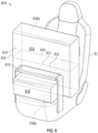
- FIG. 5 is a perspective view of the inflatable airbag assembly 100 of FIGS. 1A-2B , and 2-4, with the inflatable airbag cushion 130 at least partially deployed.
- the vehicle seating position 30 and seat 32 are shown for reference.
- the utility component 110 is shown mounted to the seat base 34 of the seat 32; however, in another embodiment, the utility component 110 may be mounted to the seatback 36, to the floor (not shown) of the vehicle, to a console structure (not shown), or to another vehicle structure.
- the inflatable airbag cushion 130 deploys from the housing 120 with an initial downward trajectory and then curves to deploy rearward and upward, and also forward.
- a portion of the inflatable airbag cushion 130 comprising the upper region 132, after initially deploying downward, curves and deploys upward and rearward to be disposed forward of an occupant (see the occupant 50 in FIGS. 3, 4 ) and generally rearward of the lateral member 112 of the utility component 110. Furthermore, the lower region 138, after deploying downward from the housing 120, curves and deploys forward.
- a lateral portion 137 of the inflatable airbag cushion 130 may be disposed laterally outward relative to each of the first and second support members 116, 118.
- the lateral portions 137 may be particularly beneficial to protect the occupant 50 in an oblique impact collision scenario.
- the lateral portions 137 of the inflatable airbag cushion 130 extend approximately the full height of the inflatable airbag cushion 130.
- the lateral portions 137 may extend vertically along only a portion of the height of the inflatable airbag cushion 130.
- the inflatable airbag assembly 100 may be present with one or more other airbag assemblies.
- the inflatable airbag assembly 100 of this disclosure may omit or alter the lateral portion 137 disposed in the direction of the side curtain airbag assembly to prevent the two airbag assemblies from interfering with each other.
- FIG. 6 depicts another embodiment of an inflatable airbag assembly 600 that resembles the inflatable airbag assembly 100 described above in certain respects. Accordingly, like features are designated with like reference numerals, with the leading digits incremented to "6."
- the embodiment depicted in FIG. 6 includes an inflatable airbag cushion 630 that may, in some respects, resemble the inflatable airbag cushion 130 of FIGS. 1A-1B and 2-5 . Relevant disclosure set forth above regarding similarly identified features thus may not be repeated hereafter.
- specific features of the inflatable airbag assembly 100 and related components shown in FIGS. 1A-1B and 2-5 may not be shown or identified by a reference numeral in the drawings or specifically discussed in the written description that follows.
- FIG. 6 is a partial cross-sectional perspective view of an inflatable airbag assembly 600 at least partially deployed, and having internal tethers 642, 648.
- a seat 32 is shown for reference.
- FIG. 6 illustrates the inflatable airbag assembly 600 having an inflatable airbag cushion 630 deployed from a housing 620 and at least partially inflated.
- the housing 620 is disposed within a utility component 610 or is integral to or otherwise provided by the utility component 610.
- the inflatable airbag cushion 630 comprises an upper region 632 and a lower region 638.
- the inflatable airbag cushion 630 further comprises a forward-facing panel 634, an occupant-facing panel upper region 636a, and an occupant-facing panel lower region 636b.
- a first tether 642 is disposed within the lower region 638 of the inflatable airbag cushion 630.
- the first tether 642 couples at a first end 641a to an anchor point 641b.
- the housing 620 or the utility component 610 may comprise the anchor point 641b, or the anchor point 641b may be a portion of an inner surface of an upward-facing area 634u of the forward-facing panel 634 of the lower region 638 of the inflatable airbag cushion 630.
- the first tether 642 couples at a second end 643a to an inner surface 643b of the occupant-facing panel lower region 636b.
- the second tether 648 may have a vertical dimension to limit downward expansion of the lower region 638 of the inflatable airbag cushion 630.
- Limiting downward expansion of the lower region 638 may promote forward expansion of the lower region 638 and lateral expansion of the lower region 638 to conform about knees/thighs of an occupant (see thighs/knees 58, 59 in FIGS. 3 , 4 ).
- the first tether 642 may be drawn taut and exert a force on the occupant-facing panel 636 to curve the occupant-facing panel 636a, 636b of the inflatable airbag cushion 630 rearward and upward.
- a second tether 648 is disposed within the upper region 632. More particularly, the second tether 648 couples at a first end 647a to an inner surface 647b of the forward-facing panel 634, and at a second end 649a to an inner surface 649b of the occupant-facing panel upper region 636a.
- the first tether 648 may have a longitudinal dimension to limit rearward expansion of the upper region 632 of the inflatable airbag cushion 630. Limiting rearward expansion of the upper region 632 may promote upward deployment of the upper region 632, as well as assist in configuring the upper region 632 to receive and support a head, torso, and/or pelvic region (see head 52, torso 54, pelvic region 56 in FIGS. 3 , 4 ) during a collision event.
- first tether 642 and a single second tether 648 are shown. Furthermore, the first tether 642 is oriented with a vertical plane running in a lateral direction, and the second tether 648 is oriented with a vertical plane running in a longitudinal direction. In another embodiment, a plurality of first tethers 642 may be employed, a plurality of second tethers 648 may be employed, or both. Additionally, one or more first tethers 642 may be oriented in a different direction, and one or more second tethers 648 may be oriented in a different direction.
- first first tether 642 oriented laterally and a second first tether 642 oriented longitudinally such that the two first tethers 642 intersect or cross each other.
- first and second tethers 642, 648 are anticipated by the present disclosure.
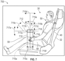
- FIG. 7 is a side view of an inflatable airbag assembly 700 wherein a utility component 710 is supported by a support member 716 on one side only.
- a seat 32 and an occupant 50 are shown for reference.
- the occupant 50 may be restrained by a harness 40.
- the utility component 710 comprises the support member 716 disposed toward one side of the vehicle seating position 30 and a lateral member 712.
- the lateral member 712 may constitute (e.g., serve as) or comprise (e.g., contain) a housing 720 to house one or more components of the inflatable airbag assembly 700.
- the utility component 710 may be adjustable and/or stowable.
- the lateral member 712 may couple at the support member 716 via an articulable joint or hinge 717a whereby the lateral member 712 may pivot 717c about a longitudinal axis 717b of the vehicle, which may facilitate stowing and deploying the utility component 710.
- the articulable joint or hinge 717a may permit the lateral member 712 to tilt 717e about a lateral axis 717d.
- the lateral member 712 may be adjustable 718 in an upward and downward direction relative to the vehicle seating position 30.
- the support member 716 may couple to the seat base 34 (or other vehicle component) via an articulable joint 715a.
- the articulable joint 715a may permit fore and aft adjustment 715c of the utility component 710 relative to the vehicle seating position 30 to suit a particular occupant 50.
- the articulable joint 715a may permit rotation 715e of the support member 716 (and, hence, the utility component 710) about a vertical axis 715b.
- the articulable joint 715a may permit the support member 716 to rotate fore and aft about the articulable joint 715a such that support member 716 of the utility component 710 is rotatable 715d relative to the vehicle seating position 30 about an axis 715f that is transverse to a longitudinal axis of the vehicle in a longitudinal direction of the vehicle seating position 30.
- Articulations enabled by the articulable joint 715a and/or the articulable joint 717a may facilitate stowing the utility component 710 or lateral member 712 to permit ingress/egress to/from the vehicle seating position 30, and may facilitate deploying and positioning the utility component 710 for use by the occupant 50 of the vehicle seating position 30.
- each articulable joint 715a, 717a may be configured to lock into one or more predetermined positions.
- the utility component 710 may be configured to communicate to a sensor or onboard computer of the vehicle that each articulable joint 715a, 717a is locked in such a position. This communication may allow disablement of the inflatable airbag assembly 700 when any articulable joint 715a, 717a is not in a locked position.
- FIG. 8 is a perspective view of an inflatable airbag assembly 800 having a multi-chamber inflatable airbag cushion 830.
- the seat 32 and a utility component 810 are shown for reference.
- the inflatable airbag cushion 830 comprises an upper chamber 832 and a lower chamber 838.
- the upper chamber 832 and lower chamber 838 may be formed of a single contiguous portion of material (as by sewing, RF welding, adhesive, etc.) whereby a first seam 831 and a second seam 833 are formed, and whereby an interstitial member 835 is interposed between the upper and lower chamber 832, 838.
- the upper and lower chambers 832, 838 are formed together of a single contiguous portion of material and the interstitial member 835 is coupled between the upper and lower chambers 832, 838 by the seams 831, 833.
- the upper chamber 832 may be formed of a single contiguous portion of material
- the second chamber 838 may be formed of another single contiguous portion of material
- the upper and lower chambers 832, 838 may then be coupled together at the first seam 831 and second seam 833, whereby the interstitial member 835 is formed of portions of both the upper and lower chambers 832, 838.
- Other methods of forming the distinct upper and lower chamber 832, 838 are anticipated by this disclosure.
- the lower chamber 838 deploys downward, a portion of the lower chamber 838 curves rearward, and the upper chamber 832 subsequently begins expanding.
- the upper chamber 832 expands upward from the lower chamber 838.
- the inflatable airbag cushion 830 may be configured to inflate the upper chamber 832 following a fixed period of time after deployment of the inflatable airbag cushion 830 commences, whereby the lower chamber 838 is permitted to expand downward and rearward to at least a particular degree before the upper chamber 832 begins to inflate.
- the inflatable airbag cushion 830 may be configured to begin inflating both the upper and lower chambers 832, 838 essentially simultaneously, but at different rates so that the upper chamber 832 expands more slowly and reaches full deployment a predetermined time after full deployment of the lower chamber 838.
- Other methods of differentiating the inflation of the upper and lower chambers 832, 838 are anticipated by this disclosure.
- An embodiment having distinct upper and lower chambers 832, 838 may facilitate positioning of the upper chamber 832 to properly receive and support a head and/or torso of an occupant (see the head 52, torso 54, and occupant 50 in FIGS. 3 , 4 ).
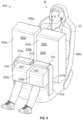
- FIG. 9 is a perspective view of an inflatable airbag assembly 900 having multiple inflatable airbag cushions 930a, 930b.
- a utility component system 910 comprises a first utility component 910a and a second utility component 910b.
- the first utility component 910a comprises a lateral member 912 and a support member 916.
- the second utility component 910b comprises a lateral member 914 and a support member 918.
- Each lateral member 912, 914 may constitute (serve as) or comprise (enclose) a housing 920, 922 of the inflatable airbag assembly 900.
- a first inflatable airbag cushion 930a may deploy from the housing 920, and a second inflatable airbag cushion 930b may deploy from the housing 922.
- the first inflatable airbag cushion 930a comprises a first upper region 932a and a first lower region 938a.
- the second inflatable airbag cushion 930b comprises a second upper region 932b and a second lower region 938b.
- the first and second upper regions 932a, 932b may be essentially analogous to upper region 132 of the inflatable airbag cushion 130 of FIGS. 3 , 4 .
- the lower regions 938a, 938b may be essentially analogous to the lower region 138 of the inflatable airbag cushion 130 of FIGS. 3 , 4 .
- the first and second inflatable airbag cushions 930a, 930b may be analogous to other embodiments of the present disclosure.
- a gap is shown between the first and second utility components 910a, 910b, and between the first and second inflatable airbag cushions 930a, 930b.
- the first and second utility components 910a. 910b may couple such that there is no lateral gap.
- Coupled refers to any form of interaction between two or more entities, including mechanical, electrical, magnetic, electromagnetic, fluid, and thermal interaction. Two components may be coupled to each other even though they are not in direct contact with each other.
- a and “an” can be described as one but not limited to one.
- the disclosure may recite an inflator having an initiator, the disclosure also contemplates that the inflator can have more than one initiator.
Landscapes
- Engineering & Computer Science (AREA)
- Mechanical Engineering (AREA)
- Physics & Mathematics (AREA)
- Fluid Mechanics (AREA)
- Transportation (AREA)
- Air Bags (AREA)
- Seats For Vehicles (AREA)
Claims (13)
- Fahrzeugsitzposition (30) mit einer Airbaganordnung (100, 600, 700, 800, 900), umfassend:
ein Insassenzubehör, umfassend:einen ersten Arm (116, 616, 716, 916), der mit der Fahrzeugsitzposition (30) an mindestens einer lateralen Seite der Fahrzeugsitzposition (30) gekoppelt ist;eine Nutzkomponente (110, 610, 710, 810, 910a), die mit dem Arm (116, 616, 716, 916) gekoppelt und konfiguriert ist, um sich über die Fahrzeugsitzposition (30) lateral zu erstrecken; undeinen Airbag (130, 630, 830, 930a), der innerhalb der Nutzkomponente (110, 610, 710, 810, 910a) eingerichtet ist, dadurch gekennzeichnet, dass der sich Airbag (130, 630, 830, 930a) in einer nach unten gerichteten Bahn entfaltet und sich um die Nutzkomponente (110, 610, 710, 810, 910a) herum in einer nach hinten gerichteten und nach oben gerichteten Bahn zwischen der Nutzkomponente (110, 610, 710, 810, 910a) und einer Sitzlehne (36) der Fahrzeugsitzposition (30) wölbt. - Fahrzeugsitzposition mit einer Airbaganordnung (100, 600, 700, 800, 900) nach Anspruch 1, wobei die Nutzkomponente (110, 610, 710, 810, 91 0a) zwischen einer verstauten Position und einer Gebrauchsposition bewegbar ist, wobei, in der Gebrauchsposition, die Nutzkomponente (110, 610, 710, 810, 910a) mindestens teilweise über der Fahrzeugsitzposition (30) eingerichtet ist.
- Fahrzeugsitzposition mit einer Airbaganordnung (100, 600, 700, 800, 900) nach einem der Ansprüche 1 und 2, wobei der erste Arm (116, 616, 716, 916) relativ zu der Fahrzeugsitzposition (30) in einer Längsrichtung der Fahrzeugsitzposition (30) drehbar ist.
- Fahrzeugsitzposition mit einer Airbaganordnung (100, 600, 700, 800, 900) nach einem der Ansprüche 1 bis 3, wobei die Nutzkomponente (110, 610, 710, 810, 910a) relativ zu dem ersten Arm (116, 616, 716, 916) in einer lateralen Richtung von der Fahrzeugsitzposition (30) weg rotiert.
- Fahrzeugsitzposition mit einer Airbaganordnung (100, 600, 700, 800, 900) nach einem der Ansprüche 1 bis 4, wobei die Nutzkomponente (110, 610, 710, 810, 910a) in einer nach oben gerichteten und nach unten gerichteten Richtung relativ zu der Fahrzeugsitzposition (30) und in einer nach vorne gerichteten und nach hinten gerichteten Richtung relativ zu der Fahrzeugsitzposition (30) einstellbar ist.
- Fahrzeugsitzposition mit einer Airbaganordnung (100, 600, 700, 800, 900) nach einem der Ansprüche 1 bis 5, wobei die Nutzkomponente (110, 610, 710, 810, 910a) eine Abdeckung auf einer Bodenoberfläche der Nutzkomponente (110, 610, 710, 810, 910a) umfasst, wobei sich die Abdeckung bei einer Entfaltung des Airbags (130) öffnet.
- Fahrzeugsitzposition mit einer Airbaganordnung (100, 600, 700, 800, 900) nach einem der Ansprüche 1 bis 6, wobei das Insassenzubehör ferner einen zweiten Arm (118) umfasst, der mit der Fahrzeugsitzposition (30) an einer gegenüberliegenden lateralen Seite der Fahrzeugsitzposition (30) des ersten Arms (116) verbunden ist, wobei der zweite Arm (118) mit der Nutzkomponente (110, 610, 710, 810, 910a) verbunden ist und die Nutzkomponente (110, 610, 710, 810, 910a) konfiguriert ist, um sich über die Fahrzeugsitzposition (30) von dem ersten Arm (116, 616, 716) zu dem zweiten Arm (118) lateral zu erstrecken.
- Fahrzeugsitzposition mit einer Airbaganordnung (900) nach einem der Ansprüche 1 bis 6, wobei das Insassenzubehör ferner einen zweiten Arm (918) umfasst, der mit der Fahrzeugsitzposition (30) an einer gegenüberliegenden lateralen Seite der Fahrzeugsitzposition (30) des ersten Arms (916) verbunden ist, wobei der zweite Arm (918) mit einer zweiten Nutzkomponente (910b) verbunden ist.
- Fahrzeugsitzposition mit einer Airbaganordnung (900) nach Anspruch 8, wobei der Airbag (930a) innerhalb der Nutzkomponente (910a) eingerichtet ist und ein zweiter Airbag (930b) innerhalb der zweiten Nutzkomponente (910b) eingerichtet ist, wobei sich der zweite Airbag (930b) in einer nach unten gerichteten Bahn entfaltet und sich um die zweite Nutzkomponente (910b) herum in einer nach hinten gerichteten und nach oben gerichteten Bahn zwischen der zweiten Nutzkomponente (910b) und der Fahrzeugsitzposition (30) wölbt.
- Fahrzeugsitzposition mit einer Airbaganordnung (900) nach Anspruch 9, wobei die Nutzkomponente (910a) konfiguriert ist, um sich von einer lateralen Seite der Fahrzeugsitzposition (30) über die Fahrzeugsitzposition (30) zu erstrecken und die zweite Nutzkomponente (910b) konfiguriert ist, um sich von der gegenüberliegenden lateralen Seite der Fahrzeugsitzposition (30) über die Fahrzeugsitzposition (30) zu erstrecken.
- Fahrzeugsitzposition mit einer Airbaganordnung (100, 600, 700, 800, 900) nach einem der Ansprüche 1 bis 10, ferner umfassend einen Gasgenerator (124a, 124b, 124c, 124x), der innerhalb der Nutzkomponente (110, 610, 710, 810, 910a) eingerichtet ist.
- Fahrzeugsitzposition mit einer Airbaganordnung (100, 600, 700, 800, 900) nach einem der Ansprüche 1 bis 10, ferner umfassend einen Gasgenerator (124a), der innerhalb eines Sitzes (32) der Fahrzeugsitzposition (30) zu montieren ist, und einen Schlauch (126a), der innerhalb des ersten Arms (116, 616, 716, 916) eingerichtet ist, wobei der Schlauch den Gasgenerator mit dem Airbag (130) verbindet, wobei dem Airbag (130) von dem Gasgenerator über den Schlauch Füllgas zugeführt wird.
- Fahrzeugsitzposition mit einer Airbaganordnung (100, 600, 700, 800, 900) nach einem der Ansprüche 1 bis 12, ferner umfassend einen Haltegurt (642) mit einem ersten Ende (643a), das mit einer Innenoberfläche (643b) einer dem Insassen zugewandten Platte (636b) des Airbags (130, 630, 830, 930a, 930b) gekoppelt ist, und einem zweiten Ende (641a), das mit einem Verankerungspunkt (64lb) gekoppelt ist, wobei während der Entfaltung der Haltegurt (642) straff gezogen ist und eine Kraft auf die dem Insassen zugewandte Platte (636b) ausübt, um die dem Insassen zugewandte Platte (636b) des Airbagkissens (130, 630, 830, 930a, 930b) nach hinten und nach oben zu wölben.
Applications Claiming Priority (2)
| Application Number | Priority Date | Filing Date | Title |
|---|---|---|---|
| US16/597,653 US11292420B2 (en) | 2019-10-09 | 2019-10-09 | Inflatable airbag assemblies for a utility component-equipped vehicle seating position |
| PCT/US2020/054807 WO2021072093A1 (en) | 2019-10-09 | 2020-10-08 | Inflatable airbag assemblies for a utility component-equipped vehicle seating position |
Publications (2)
| Publication Number | Publication Date |
|---|---|
| EP4041602A1 EP4041602A1 (de) | 2022-08-17 |
| EP4041602B1 true EP4041602B1 (de) | 2024-08-28 |
Family
ID=73038429
Family Applications (1)
| Application Number | Title | Priority Date | Filing Date |
|---|---|---|---|
| EP20799917.8A Active EP4041602B1 (de) | 2019-10-09 | 2020-10-08 | Aufblasbare airbaganordnungen für eine mit einer versorgungskomponente ausgestattete fahrzeugsitzposition |
Country Status (5)
| Country | Link |
|---|---|
| US (1) | US11292420B2 (de) |
| EP (1) | EP4041602B1 (de) |
| JP (1) | JP7300558B2 (de) |
| CN (1) | CN114514149B (de) |
| WO (1) | WO2021072093A1 (de) |
Families Citing this family (7)
| Publication number | Priority date | Publication date | Assignee | Title |
|---|---|---|---|---|
| US11358558B2 (en) * | 2020-07-07 | 2022-06-14 | ZF Passive Safety Systems US Inc. | Leg restraining airbag |
| US11648906B2 (en) * | 2021-02-11 | 2023-05-16 | Ford Global Technologies, Llc | Airbag assembly |
| US11364869B1 (en) * | 2021-02-19 | 2022-06-21 | GM Global Technology Operations LLC | Thorax and thigh airbag system for reclined passengers |
| DE102021104687A1 (de) | 2021-02-26 | 2022-09-01 | Zf Automotive Germany Gmbh | Insassen-Rückhaltesystem sowie Fahrzeugsitzeinheit mit einem Insassen-Rückhaltesystem |
| DE102021123145A1 (de) * | 2021-09-07 | 2023-03-09 | Zf Automotive Germany Gmbh | Klapptischsystem für einen Fahrzeugsitz |
| US11702026B2 (en) * | 2021-09-14 | 2023-07-18 | Ford Global Technologies, Llc | Vehicle crossbar movable along pillars |
| US11673524B1 (en) * | 2021-11-22 | 2023-06-13 | Ford Global Technologies, Llc | Selectively inflated crossbar airbag |
Family Cites Families (17)
| Publication number | Priority date | Publication date | Assignee | Title |
|---|---|---|---|---|
| US5492361A (en) | 1995-01-26 | 1996-02-20 | Kim; Ki I. | Side airbag apparatus |
| JP4172374B2 (ja) | 2003-10-24 | 2008-10-29 | トヨタ自動車株式会社 | 乗員保護装置 |
| JP2008222200A (ja) | 2007-02-13 | 2008-09-25 | Takata Corp | 乗員拘束装置 |
| JP5126133B2 (ja) * | 2009-03-19 | 2013-01-23 | 豊田合成株式会社 | 側突用エアバッグ装置 |
| DE102012221533A1 (de) | 2012-11-26 | 2014-05-28 | Autoliv Development Ab | Rückhalteeinrichtung für einen auf einem Sitz eines Fahrzeuges befindlichen Insassen und Sitz mit einer Rückhalteeinrichtung |
| KR101614496B1 (ko) | 2013-04-08 | 2016-05-02 | 아우토리브 디벨롭먼트 아베 | 무릎 에어백 장치의 에어백 |
| KR101627125B1 (ko) | 2013-04-19 | 2016-06-14 | 아우토리브 디벨롭먼트 아베 | 무릎 에어백 장치 및 그것의 에어백 폴딩방법 |
| US9744932B1 (en) * | 2016-03-30 | 2017-08-29 | Ford Global Technologies, Llc | Upwardly inflatable vehicle airbag |
| US10618494B2 (en) * | 2017-02-28 | 2020-04-14 | Autoliv Asp, Inc. | Airbag assemblies with anchored positional tether |
| JP6537120B2 (ja) * | 2017-03-31 | 2019-07-03 | 株式会社Subaru | アームレスト |
| US10399529B2 (en) | 2017-09-25 | 2019-09-03 | Ford Global Technologies, Llc | Seat assembly with moveable arms with airbags |
| US10232815B1 (en) | 2017-10-18 | 2019-03-19 | Ford Global Technologies, Llc | Seat assembly |
| US10583797B2 (en) | 2017-10-18 | 2020-03-10 | Ford Global Technologies, Llc | Carrier for airbag |
| US10814818B2 (en) | 2017-10-25 | 2020-10-27 | Ford Global Technologies, Llc | Vehicle seating assembly with airbag carrier |
| DE102017128097A1 (de) * | 2017-11-28 | 2019-05-29 | Trw Automotive Gmbh | Modulbasiselement für ein Fahrzeuginsassen-Schutzsystem und Fahrzeuginsassen-Schutzsystem |
| US11345305B2 (en) * | 2018-09-26 | 2022-05-31 | Trw Vehicle Safety Systems Inc. | Adaptive airbag for protecting occupants in a vehicle |
| KR102614144B1 (ko) * | 2018-10-17 | 2023-12-15 | 현대자동차주식회사 | 차량 테이블용 에어백 |
-
2019
- 2019-10-09 US US16/597,653 patent/US11292420B2/en active Active
-
2020
- 2020-10-08 EP EP20799917.8A patent/EP4041602B1/de active Active
- 2020-10-08 JP JP2022517294A patent/JP7300558B2/ja active Active
- 2020-10-08 WO PCT/US2020/054807 patent/WO2021072093A1/en not_active Ceased
- 2020-10-08 CN CN202080066627.0A patent/CN114514149B/zh active Active
Also Published As
| Publication number | Publication date |
|---|---|
| US20210107426A1 (en) | 2021-04-15 |
| CN114514149B (zh) | 2024-01-02 |
| EP4041602A1 (de) | 2022-08-17 |
| CN114514149A (zh) | 2022-05-17 |
| JP2022548290A (ja) | 2022-11-17 |
| JP7300558B2 (ja) | 2023-06-29 |
| US11292420B2 (en) | 2022-04-05 |
| WO2021072093A1 (en) | 2021-04-15 |
Similar Documents
| Publication | Publication Date | Title |
|---|---|---|
| EP4041602B1 (de) | Aufblasbare airbaganordnungen für eine mit einer versorgungskomponente ausgestattete fahrzeugsitzposition | |
| US9487177B2 (en) | Airbag assemblies for vehicles with generous leg room | |
| KR102614143B1 (ko) | 차량용 멀티 전방에어백 및 이를 이용한 에어백 전개시스템 | |
| US10246043B2 (en) | Overhead airbag assemblies | |
| JP6842444B2 (ja) | 個別膨張式二段クッションエアバッグ | |
| US10836343B2 (en) | Airbag device | |
| KR102305270B1 (ko) | 에어백 장치 및 에어백 장치가 제공된 차량 좌석 | |
| US10336278B2 (en) | Inflatable airbag harness assemblies | |
| US10632956B2 (en) | Inflatable safety restraint system for protecting a rear seat occupant | |
| US10272865B2 (en) | Arm rest | |
| KR101708217B1 (ko) | 차량용 에어백 장치 | |
| JPH04224438A (ja) | 自動車の衝突事故の際の乗客防護装置 | |
| WO2000050270A1 (en) | Inflatable protection apparatus | |
| KR20230031555A (ko) | 차량의 시트 에어백 장치 | |
| US9272681B1 (en) | Knee airbag deployable from a side panel | |
| KR102154195B1 (ko) | 자동차의 에어백 장치 | |
| US11214214B2 (en) | Vehicle seat incorporating a seat bottom front edge airbag | |
| KR102729837B1 (ko) | 자동차의 에어백 장치 | |
| KR102755190B1 (ko) | 자동차의 에어백 장치 | |
| KR101807660B1 (ko) | 자동차의 조수석 에어백 | |
| CN114312650A (zh) | 用于车辆的乘员碰撞保护装置 | |
| KR20160009967A (ko) | 동승석 에어백 장치 | |
| JP7186746B2 (ja) | 乗員下肢拘束装置 | |
| KR102626944B1 (ko) | 자동차의 파 사이드 에어백 장치 및 그의 폴딩 방법 | |
| JP2016043712A (ja) | 車両用エアバッグ装置 |
Legal Events
| Date | Code | Title | Description |
|---|---|---|---|
| STAA | Information on the status of an ep patent application or granted ep patent |
Free format text: STATUS: UNKNOWN |
|
| STAA | Information on the status of an ep patent application or granted ep patent |
Free format text: STATUS: THE INTERNATIONAL PUBLICATION HAS BEEN MADE |
|
| PUAI | Public reference made under article 153(3) epc to a published international application that has entered the european phase |
Free format text: ORIGINAL CODE: 0009012 |
|
| STAA | Information on the status of an ep patent application or granted ep patent |
Free format text: STATUS: REQUEST FOR EXAMINATION WAS MADE |
|
| 17P | Request for examination filed |
Effective date: 20220502 |
|
| AK | Designated contracting states |
Kind code of ref document: A1 Designated state(s): AL AT BE BG CH CY CZ DE DK EE ES FI FR GB GR HR HU IE IS IT LI LT LU LV MC MK MT NL NO PL PT RO RS SE SI SK SM TR |
|
| DAV | Request for validation of the european patent (deleted) | ||
| DAX | Request for extension of the european patent (deleted) | ||
| GRAP | Despatch of communication of intention to grant a patent |
Free format text: ORIGINAL CODE: EPIDOSNIGR1 |
|
| STAA | Information on the status of an ep patent application or granted ep patent |
Free format text: STATUS: GRANT OF PATENT IS INTENDED |
|
| INTG | Intention to grant announced |
Effective date: 20240326 |
|
| GRAS | Grant fee paid |
Free format text: ORIGINAL CODE: EPIDOSNIGR3 |
|
| GRAA | (expected) grant |
Free format text: ORIGINAL CODE: 0009210 |
|
| STAA | Information on the status of an ep patent application or granted ep patent |
Free format text: STATUS: THE PATENT HAS BEEN GRANTED |
|
| AK | Designated contracting states |
Kind code of ref document: B1 Designated state(s): AL AT BE BG CH CY CZ DE DK EE ES FI FR GB GR HR HU IE IS IT LI LT LU LV MC MK MT NL NO PL PT RO RS SE SI SK SM TR |
|
| REG | Reference to a national code |
Ref country code: CH Ref legal event code: EP |
|
| REG | Reference to a national code |
Ref country code: DE Ref legal event code: R096 Ref document number: 602020036761 Country of ref document: DE |
|
| REG | Reference to a national code |
Ref country code: IE Ref legal event code: FG4D |
|
| REG | Reference to a national code |
Ref country code: LT Ref legal event code: MG9D |
|
| PGFP | Annual fee paid to national office [announced via postgrant information from national office to epo] |
Ref country code: DE Payment date: 20241029 Year of fee payment: 5 |
|
| PG25 | Lapsed in a contracting state [announced via postgrant information from national office to epo] |
Ref country code: NO Free format text: LAPSE BECAUSE OF FAILURE TO SUBMIT A TRANSLATION OF THE DESCRIPTION OR TO PAY THE FEE WITHIN THE PRESCRIBED TIME-LIMIT Effective date: 20241128 |
|
| REG | Reference to a national code |
Ref country code: AT Ref legal event code: MK05 Ref document number: 1717630 Country of ref document: AT Kind code of ref document: T Effective date: 20240828 |
|
| PG25 | Lapsed in a contracting state [announced via postgrant information from national office to epo] |
Ref country code: NL Free format text: LAPSE BECAUSE OF FAILURE TO SUBMIT A TRANSLATION OF THE DESCRIPTION OR TO PAY THE FEE WITHIN THE PRESCRIBED TIME-LIMIT Effective date: 20240828 Ref country code: PT Free format text: LAPSE BECAUSE OF FAILURE TO SUBMIT A TRANSLATION OF THE DESCRIPTION OR TO PAY THE FEE WITHIN THE PRESCRIBED TIME-LIMIT Effective date: 20241230 Ref country code: PL Free format text: LAPSE BECAUSE OF FAILURE TO SUBMIT A TRANSLATION OF THE DESCRIPTION OR TO PAY THE FEE WITHIN THE PRESCRIBED TIME-LIMIT Effective date: 20240828 Ref country code: GR Free format text: LAPSE BECAUSE OF FAILURE TO SUBMIT A TRANSLATION OF THE DESCRIPTION OR TO PAY THE FEE WITHIN THE PRESCRIBED TIME-LIMIT Effective date: 20241129 Ref country code: FI Free format text: LAPSE BECAUSE OF FAILURE TO SUBMIT A TRANSLATION OF THE DESCRIPTION OR TO PAY THE FEE WITHIN THE PRESCRIBED TIME-LIMIT Effective date: 20240828 |
|
| PGFP | Annual fee paid to national office [announced via postgrant information from national office to epo] |
Ref country code: GB Payment date: 20241022 Year of fee payment: 5 |
|
| PG25 | Lapsed in a contracting state [announced via postgrant information from national office to epo] |
Ref country code: BG Free format text: LAPSE BECAUSE OF FAILURE TO SUBMIT A TRANSLATION OF THE DESCRIPTION OR TO PAY THE FEE WITHIN THE PRESCRIBED TIME-LIMIT Effective date: 20240828 |
|
| PG25 | Lapsed in a contracting state [announced via postgrant information from national office to epo] |
Ref country code: LV Free format text: LAPSE BECAUSE OF FAILURE TO SUBMIT A TRANSLATION OF THE DESCRIPTION OR TO PAY THE FEE WITHIN THE PRESCRIBED TIME-LIMIT Effective date: 20240828 |
|
| REG | Reference to a national code |
Ref country code: NL Ref legal event code: MP Effective date: 20240828 |
|
| PG25 | Lapsed in a contracting state [announced via postgrant information from national office to epo] |
Ref country code: AT Free format text: LAPSE BECAUSE OF FAILURE TO SUBMIT A TRANSLATION OF THE DESCRIPTION OR TO PAY THE FEE WITHIN THE PRESCRIBED TIME-LIMIT Effective date: 20240828 Ref country code: IS Free format text: LAPSE BECAUSE OF FAILURE TO SUBMIT A TRANSLATION OF THE DESCRIPTION OR TO PAY THE FEE WITHIN THE PRESCRIBED TIME-LIMIT Effective date: 20241228 |
|
| PGFP | Annual fee paid to national office [announced via postgrant information from national office to epo] |
Ref country code: FR Payment date: 20241025 Year of fee payment: 5 |
|
| PG25 | Lapsed in a contracting state [announced via postgrant information from national office to epo] |
Ref country code: HR Free format text: LAPSE BECAUSE OF FAILURE TO SUBMIT A TRANSLATION OF THE DESCRIPTION OR TO PAY THE FEE WITHIN THE PRESCRIBED TIME-LIMIT Effective date: 20240828 |
|
| PG25 | Lapsed in a contracting state [announced via postgrant information from national office to epo] |
Ref country code: ES Free format text: LAPSE BECAUSE OF FAILURE TO SUBMIT A TRANSLATION OF THE DESCRIPTION OR TO PAY THE FEE WITHIN THE PRESCRIBED TIME-LIMIT Effective date: 20240828 Ref country code: RS Free format text: LAPSE BECAUSE OF FAILURE TO SUBMIT A TRANSLATION OF THE DESCRIPTION OR TO PAY THE FEE WITHIN THE PRESCRIBED TIME-LIMIT Effective date: 20241128 |
|
| PG25 | Lapsed in a contracting state [announced via postgrant information from national office to epo] |
Ref country code: RS Free format text: LAPSE BECAUSE OF FAILURE TO SUBMIT A TRANSLATION OF THE DESCRIPTION OR TO PAY THE FEE WITHIN THE PRESCRIBED TIME-LIMIT Effective date: 20241128 Ref country code: PT Free format text: LAPSE BECAUSE OF FAILURE TO SUBMIT A TRANSLATION OF THE DESCRIPTION OR TO PAY THE FEE WITHIN THE PRESCRIBED TIME-LIMIT Effective date: 20241230 Ref country code: PL Free format text: LAPSE BECAUSE OF FAILURE TO SUBMIT A TRANSLATION OF THE DESCRIPTION OR TO PAY THE FEE WITHIN THE PRESCRIBED TIME-LIMIT Effective date: 20240828 Ref country code: NO Free format text: LAPSE BECAUSE OF FAILURE TO SUBMIT A TRANSLATION OF THE DESCRIPTION OR TO PAY THE FEE WITHIN THE PRESCRIBED TIME-LIMIT Effective date: 20241128 Ref country code: NL Free format text: LAPSE BECAUSE OF FAILURE TO SUBMIT A TRANSLATION OF THE DESCRIPTION OR TO PAY THE FEE WITHIN THE PRESCRIBED TIME-LIMIT Effective date: 20240828 Ref country code: LV Free format text: LAPSE BECAUSE OF FAILURE TO SUBMIT A TRANSLATION OF THE DESCRIPTION OR TO PAY THE FEE WITHIN THE PRESCRIBED TIME-LIMIT Effective date: 20240828 Ref country code: IS Free format text: LAPSE BECAUSE OF FAILURE TO SUBMIT A TRANSLATION OF THE DESCRIPTION OR TO PAY THE FEE WITHIN THE PRESCRIBED TIME-LIMIT Effective date: 20241228 Ref country code: HR Free format text: LAPSE BECAUSE OF FAILURE TO SUBMIT A TRANSLATION OF THE DESCRIPTION OR TO PAY THE FEE WITHIN THE PRESCRIBED TIME-LIMIT Effective date: 20240828 Ref country code: GR Free format text: LAPSE BECAUSE OF FAILURE TO SUBMIT A TRANSLATION OF THE DESCRIPTION OR TO PAY THE FEE WITHIN THE PRESCRIBED TIME-LIMIT Effective date: 20241129 Ref country code: FI Free format text: LAPSE BECAUSE OF FAILURE TO SUBMIT A TRANSLATION OF THE DESCRIPTION OR TO PAY THE FEE WITHIN THE PRESCRIBED TIME-LIMIT Effective date: 20240828 Ref country code: ES Free format text: LAPSE BECAUSE OF FAILURE TO SUBMIT A TRANSLATION OF THE DESCRIPTION OR TO PAY THE FEE WITHIN THE PRESCRIBED TIME-LIMIT Effective date: 20240828 Ref country code: BG Free format text: LAPSE BECAUSE OF FAILURE TO SUBMIT A TRANSLATION OF THE DESCRIPTION OR TO PAY THE FEE WITHIN THE PRESCRIBED TIME-LIMIT Effective date: 20240828 Ref country code: AT Free format text: LAPSE BECAUSE OF FAILURE TO SUBMIT A TRANSLATION OF THE DESCRIPTION OR TO PAY THE FEE WITHIN THE PRESCRIBED TIME-LIMIT Effective date: 20240828 |
|
| PG25 | Lapsed in a contracting state [announced via postgrant information from national office to epo] |
Ref country code: RO Free format text: LAPSE BECAUSE OF FAILURE TO SUBMIT A TRANSLATION OF THE DESCRIPTION OR TO PAY THE FEE WITHIN THE PRESCRIBED TIME-LIMIT Effective date: 20240828 Ref country code: SM Free format text: LAPSE BECAUSE OF FAILURE TO SUBMIT A TRANSLATION OF THE DESCRIPTION OR TO PAY THE FEE WITHIN THE PRESCRIBED TIME-LIMIT Effective date: 20240828 Ref country code: DK Free format text: LAPSE BECAUSE OF FAILURE TO SUBMIT A TRANSLATION OF THE DESCRIPTION OR TO PAY THE FEE WITHIN THE PRESCRIBED TIME-LIMIT Effective date: 20240828 |
|
| PG25 | Lapsed in a contracting state [announced via postgrant information from national office to epo] |
Ref country code: EE Free format text: LAPSE BECAUSE OF FAILURE TO SUBMIT A TRANSLATION OF THE DESCRIPTION OR TO PAY THE FEE WITHIN THE PRESCRIBED TIME-LIMIT Effective date: 20240828 |
|
| PG25 | Lapsed in a contracting state [announced via postgrant information from national office to epo] |
Ref country code: CZ Free format text: LAPSE BECAUSE OF FAILURE TO SUBMIT A TRANSLATION OF THE DESCRIPTION OR TO PAY THE FEE WITHIN THE PRESCRIBED TIME-LIMIT Effective date: 20240828 |
|
| PG25 | Lapsed in a contracting state [announced via postgrant information from national office to epo] |
Ref country code: IT Free format text: LAPSE BECAUSE OF FAILURE TO SUBMIT A TRANSLATION OF THE DESCRIPTION OR TO PAY THE FEE WITHIN THE PRESCRIBED TIME-LIMIT Effective date: 20240828 Ref country code: SK Free format text: LAPSE BECAUSE OF FAILURE TO SUBMIT A TRANSLATION OF THE DESCRIPTION OR TO PAY THE FEE WITHIN THE PRESCRIBED TIME-LIMIT Effective date: 20240828 |
|
| REG | Reference to a national code |
Ref country code: CH Ref legal event code: PL Ref country code: DE Ref legal event code: R097 Ref document number: 602020036761 Country of ref document: DE |
|
| PLBE | No opposition filed within time limit |
Free format text: ORIGINAL CODE: 0009261 |
|
| STAA | Information on the status of an ep patent application or granted ep patent |
Free format text: STATUS: NO OPPOSITION FILED WITHIN TIME LIMIT |
|
| PG25 | Lapsed in a contracting state [announced via postgrant information from national office to epo] |
Ref country code: MC Free format text: LAPSE BECAUSE OF FAILURE TO SUBMIT A TRANSLATION OF THE DESCRIPTION OR TO PAY THE FEE WITHIN THE PRESCRIBED TIME-LIMIT Effective date: 20240828 |
|
| PG25 | Lapsed in a contracting state [announced via postgrant information from national office to epo] |
Ref country code: LU Free format text: LAPSE BECAUSE OF NON-PAYMENT OF DUE FEES Effective date: 20241008 Ref country code: BE Free format text: LAPSE BECAUSE OF NON-PAYMENT OF DUE FEES Effective date: 20241031 |
|
| PG25 | Lapsed in a contracting state [announced via postgrant information from national office to epo] |
Ref country code: CH Free format text: LAPSE BECAUSE OF NON-PAYMENT OF DUE FEES Effective date: 20241031 |
|
| 26N | No opposition filed |
Effective date: 20250530 |
|
| REG | Reference to a national code |
Ref country code: BE Ref legal event code: MM Effective date: 20241031 |
|
| PG25 | Lapsed in a contracting state [announced via postgrant information from national office to epo] |
Ref country code: SE Free format text: LAPSE BECAUSE OF FAILURE TO SUBMIT A TRANSLATION OF THE DESCRIPTION OR TO PAY THE FEE WITHIN THE PRESCRIBED TIME-LIMIT Effective date: 20240828 |
|
| PG25 | Lapsed in a contracting state [announced via postgrant information from national office to epo] |
Ref country code: IE Free format text: LAPSE BECAUSE OF NON-PAYMENT OF DUE FEES Effective date: 20241008 |