EP4041364B1 - Verfahren zu vorbereitung von ballonexpandierbaren kathetern für herz- und gefässeingriffe - Google Patents
Verfahren zu vorbereitung von ballonexpandierbaren kathetern für herz- und gefässeingriffe Download PDFInfo
- Publication number
- EP4041364B1 EP4041364B1 EP20793524.8A EP20793524A EP4041364B1 EP 4041364 B1 EP4041364 B1 EP 4041364B1 EP 20793524 A EP20793524 A EP 20793524A EP 4041364 B1 EP4041364 B1 EP 4041364B1
- Authority
- EP
- European Patent Office
- Prior art keywords
- balloon catheter
- balloon
- inflator
- air
- inflation lumen
- Prior art date
- Legal status (The legal status is an assumption and is not a legal conclusion. Google has not performed a legal analysis and makes no representation as to the accuracy of the status listed.)
- Active
Links
Images


Classifications
-
- A—HUMAN NECESSITIES
- A61—MEDICAL OR VETERINARY SCIENCE; HYGIENE
- A61M—DEVICES FOR INTRODUCING MEDIA INTO, OR ONTO, THE BODY; DEVICES FOR TRANSDUCING BODY MEDIA OR FOR TAKING MEDIA FROM THE BODY; DEVICES FOR PRODUCING OR ENDING SLEEP OR STUPOR
- A61M25/00—Catheters; Hollow probes
- A61M25/10—Balloon catheters
-
- A—HUMAN NECESSITIES
- A61—MEDICAL OR VETERINARY SCIENCE; HYGIENE
- A61M—DEVICES FOR INTRODUCING MEDIA INTO, OR ONTO, THE BODY; DEVICES FOR TRANSDUCING BODY MEDIA OR FOR TAKING MEDIA FROM THE BODY; DEVICES FOR PRODUCING OR ENDING SLEEP OR STUPOR
- A61M25/00—Catheters; Hollow probes
- A61M25/10—Balloon catheters
- A61M25/1018—Balloon inflating or inflation-control devices
- A61M25/10181—Means for forcing inflation fluid into the balloon
- A61M25/10182—Injector syringes
-
- A—HUMAN NECESSITIES
- A61—MEDICAL OR VETERINARY SCIENCE; HYGIENE
- A61M—DEVICES FOR INTRODUCING MEDIA INTO, OR ONTO, THE BODY; DEVICES FOR TRANSDUCING BODY MEDIA OR FOR TAKING MEDIA FROM THE BODY; DEVICES FOR PRODUCING OR ENDING SLEEP OR STUPOR
- A61M25/00—Catheters; Hollow probes
- A61M25/10—Balloon catheters
- A61M25/104—Balloon catheters used for angioplasty
-
- A—HUMAN NECESSITIES
- A61—MEDICAL OR VETERINARY SCIENCE; HYGIENE
- A61M—DEVICES FOR INTRODUCING MEDIA INTO, OR ONTO, THE BODY; DEVICES FOR TRANSDUCING BODY MEDIA OR FOR TAKING MEDIA FROM THE BODY; DEVICES FOR PRODUCING OR ENDING SLEEP OR STUPOR
- A61M25/00—Catheters; Hollow probes
- A61M25/10—Balloon catheters
- A61M2025/1043—Balloon catheters with special features or adapted for special applications
- A61M2025/1061—Balloon catheters with special features or adapted for special applications having separate inflations tubes, e.g. coaxial tubes or tubes otherwise arranged apart from the catheter tube
-
- A—HUMAN NECESSITIES
- A61—MEDICAL OR VETERINARY SCIENCE; HYGIENE
- A61M—DEVICES FOR INTRODUCING MEDIA INTO, OR ONTO, THE BODY; DEVICES FOR TRANSDUCING BODY MEDIA OR FOR TAKING MEDIA FROM THE BODY; DEVICES FOR PRODUCING OR ENDING SLEEP OR STUPOR
- A61M25/00—Catheters; Hollow probes
- A61M25/10—Balloon catheters
- A61M2025/1043—Balloon catheters with special features or adapted for special applications
- A61M2025/1077—Balloon catheters with special features or adapted for special applications having a system for expelling the air out of the balloon before inflation and use
-
- A—HUMAN NECESSITIES
- A61—MEDICAL OR VETERINARY SCIENCE; HYGIENE
- A61M—DEVICES FOR INTRODUCING MEDIA INTO, OR ONTO, THE BODY; DEVICES FOR TRANSDUCING BODY MEDIA OR FOR TAKING MEDIA FROM THE BODY; DEVICES FOR PRODUCING OR ENDING SLEEP OR STUPOR
- A61M2210/00—Anatomical parts of the body
- A61M2210/12—Blood circulatory system
- A61M2210/125—Heart
Definitions
- the present disclosure relates to balloon catheters, and more particularly the invention of the present disclosure relates to a method of purging air from balloon catheters prior to use in an interventional procedure.
- Balloon catheters are conventionally used in a wide variety of medical procedures.
- a balloon is inflated during percutaneous transluminal coronary angioplasty (PTCA) to dilate a stenotic blood vessel and may also be used to deliver a stent to support the vessel lumen in an open position.
- PTCA percutaneous transluminal coronary angioplasty
- balloon inflation is accomplished by injecting an inflation fluid under pressure into an inflation lumen of a balloon catheter.
- the pressurizing inflation fluid is a saline or other physiologically inert solution which should not cause harm to the patient.
- balloon catheters must be purged of air prior to use to eliminate the risk of an air embolism entering a vessel if the system were to leak or the balloon were to rupture.
- the air also must be evacuated from the balloon to accomplish a desired inflation of the balloon using a specific volume of inflation fluid without the need to account for compression of an unknown volume of air within the balloon.
- Radiopaque contrast media either 100% or in solution with water or saline, is typically employed to fill and purge the balloon of all harmful gases. As described above, air removal is essential not only to ensure the safety of the patient but also to prevent air blocks which could limit the amount of expansion of the balloon, thereby reducing the effectiveness of the procedure.
- a common method of purging air from a balloon catheter prior to use involves creating a vacuum inside the inflation lumen of the balloon catheter, typically in conjunction with a syringe used for inflation fluid filling purposes. Inflation fluid is injected into the inflation lumen and air is drawn into the syringe. In such a procedure, air which has been purged from the catheter collects in the syringe, which is removed from the catheter so that air in the syringe may be expelled. These steps may have to be repeated multiple times to adequately purge the catheter of air, requiring a substantial amount of labor and preparation time. Depending on the size of the balloon, and therefore the volume of fluid and bubbles in the balloon catheter, the preparation time can reach up to thirty minutes. Long preparation time is particularly an issue for the larger balloon catheters such as those used to implant a replacement heart valve.
- Embodiments of the invention hereof relate to a method for purging a balloon catheter of air.
- an inflation fluid is inserted into a balloon and an inflation lumen of a balloon catheter.
- the inflation lumen is in fluid communication with the balloon.
- the balloon catheter is positioned in an inverted orientation with a distal end thereof disposed below a proximal end thereof.
- the distal end of the balloon catheter includes a balloon.
- a vibration source is positioned in direct contact with an outer surface of the balloon catheter. The balloon catheter is vibrated via the vibration source to cause air within the balloon of the balloon catheter or air within the inflation lumen of the balloon catheter to move upwards towards the proximal end of the balloon catheter.
- an inflation fluid is inserted into a balloon and an inflation lumen of a balloon catheter.
- the inflation lumen is in fluid communication with the balloon.
- the balloon catheter is positioned in an inverted orientation with a distal end thereof disposed below a proximal end thereof.
- the distal end of the balloon catheter includes a balloon.
- a vibration source is positioned in direct contact with an outer surface of the balloon catheter.
- An inflation fluid is inserted into the balloon and the inflation lumen of the balloon catheter.
- a vacuum is applied or pulled on the inflation lumen of the balloon catheter.
- the balloon catheter is vibrated via the vibration source while applying the vacuum on the inflation lumen of the balloon catheter to cause air within the balloon of the balloon catheter or air within the inflation lumen of the balloon catheter to move upwards through the inflation fluid towards the proximal end of the balloon catheter.
- an inflation fluid is inserted into a balloon and an inflation lumen of a balloon catheter.
- the inflation lumen is in fluid communication with the balloon.
- the balloon catheter is positioned in an inverted orientation with a distal end thereof disposed below a proximal end thereof.
- the distal end of the balloon catheter includes a balloon.
- a vibration source is positioned in direct contact with an outer surface of the balloon catheter.
- the balloon catheter is vibrated via the vibration source.
- a vacuum is applied or pulled on the inflation lumen of the balloon catheter. The steps of vibrating the balloon catheter and applying the vacuum are performed simultaneously.
- distal and proximal are used in the following description with respect to a position or direction relative to the treating clinician.
- distal or disally is a position distant from or in a direction away from the clinician.
- Proximal or “proximally” is a position near or in a direction toward the clinician.
- Embodiments hereof relate to a method of purging a balloon catheter of air prior to an interventional procedure. More particularly, embodiments hereof relate to the application of a vibration source to expeditiously remove bubbles, or voids, from a balloon catheter prior to use. Methods described herein substantially reduce the length of the catheter preparation time by applying a vibration source to expedite bubble removal from the balloon catheter. To facilitate the air removal process, a vibration source is placed in direct contact with certain external parts of the catheter. This vibratory action causes the entrapped bubbles to rise through the column of inflation fluid and exit the catheter. This vibratory action significantly reduces the catheter preparation time.
- the catheter preparation time may be reduced from approximately 15-30 minutes when air is purged from a relatively large balloon catheter using conventional purging methods to less than 2 minutes for the same relatively large balloon catheter using vibratory action to expeditiously remove air as described in embodiments hereof.
- the shortened catheter preparation time reduces physical strain on staff, and also reduces overall procedure time which thereby increases potential patient volume and revenue for the catheter lab center.
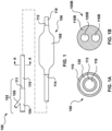
- FIGS. 1 and 1A depict an exemplary balloon catheter 100 that may be purged of air prior to use in an interventional procedure according to an embodiment hereof.
- the balloon catheter 100 may form the basis of a prosthetic heart valve delivery system, a stent delivery system, a graft delivery system, and/or a drug delivery system.
- the balloon catheter 100 may be used to deliver a balloon-expandable device (not shown), such as a replacement heart valve, a stent, a graft, a drug delivery device, or another balloon-expandable device.
- the balloon catheter 100 may be utilized in a balloon angioplasty procedure. The objective in angioplasty is to restore adequate blood flow through the affected artery, which may be accomplished by inflating a balloon of a balloon catheter within the narrowed lumen of the artery to dilate the vessel.
- the exemplary balloon catheter 100 includes a proximal portion 102 that extends out of the patient during clinical use and has a hub 104.
- the hub 104 includes a luer fitting 105 or other type of fitting that may be connected to a source of inflation fluid and may be of another construction or configuration without departing from the scope of the present invention.
- a distal portion 106 of the balloon catheter 100 is positionable at a target treatment location and includes an inflatable balloon 108, which is shown in an expanded or inflated configuration in FIG. 1 .
- the balloon 108 may be made of a biocompatible material such as a thermoplastic polyurethane (TPU) resin, styrene-ethylene-butadiene-styrene (SEBS), PEBAX ® , or the like.
- TPU thermoplastic polyurethane
- SEBS styrene-ethylene-butadiene-styrene
- PEBAX ® PEBAX ®
- the balloon catheter 100 may have an over-the-wire (OTW) coaxial catheter configuration with an outer tubular component or shaft 110 and an inner tubular component or shaft 112.
- the outer shaft 110 has a proximal end 111 coupled to the hub 104 and a distal end 114 coupled to a proximal end of the balloon 108.
- the inner shaft 112 defines a guidewire lumen 116 extending substantially the entire length of the catheter for accommodating a guidewire (not shown).
- the inner shaft 112 has a proximal end (obscured from view in FIG.
- the inner shaft 112 extends coaxially within the outer shaft 110 such that an annular inflation lumen 120 is defined between an inner surface of the outer shaft 110 and an outer surface of the inner shaft 112.
- the inflation lumen 120 thus extends within the outer shaft 110 and into the inner volume of the balloon 108 to allow inflation fluid received through an inflation port of the luer fitting 105 of the hub 104 to be delivered to the balloon 108.
- a distal end of the balloon 108 is coupled to the inner shaft 112 distal of a distal end 114 of the outer shaft 110.
- FIG. 1B is a cross-sectional view of a balloon catheter 100B according to an alternative example.
- the balloon catheter 100B includes a single catheter shaft 110B that defines an inflation lumen 120B and a guidewire lumen 116B, each extending substantially the entire length of the catheter and parallel to each other.
- one or more lumen(s) of the catheter shaft 110B may have any suitable cross-section including for example circular, elliptical, or crescent shapes.
- the balloon catheter 100B may have a rapid-exchange configuration with the guidewire lumen extending only along a distal portion of the catheter, as understood by those of ordinary skill in the art.
- the catheter shaft(s) may be formed of a polymeric material, non-exhaustive examples of which include polyethylene, polyethylene block amide (PEBA), polyamide and/or combinations thereof.
- the catheter shaft(s) or some portion thereof may be formed as a composite having a reinforcement material incorporated within a polymeric body in order to enhance strength and/or flexibility. Suitable reinforcement layers include braiding, wire mesh layers, embedded axial wires, embedded helical or circumferential wires, and the like.
- at least a proximal portion of the outer shaft 110 or catheter shaft 110B may be formed from a reinforced polymeric tube.
- the balloon catheter 100 is shown in conjunction with a stopcock 222, an inflator 224, and a vibration source 226.
- the stopcock 222, the inflator 224, and the vibration source 226 are accessories or tools that are utilized in a method of purging air from the balloon catheter 100 prior to use in an interventional procedure according to embodiments hereof.
- the stopcock 222 may be a three-way stopcock, and is configured to regulate the flow of an inflation fluid or gas therethrough, as known by persons having ordinary skill in the art. More particularly, as will be described in more detail herein, the stopcock 222 seals the balloon catheter 100 during application of a vacuum via the inflator 224 during the air purging methods described herein.
- the inflator 224 is configured to apply or pull a vacuum on the inflation lumen 120 of the balloon catheter 100 in order to purge air from the balloon 108 and the inflation lumen 120.
- the inflator 224 is a syringe.
- the inflator 224 is also configured to hold an inflation fluid therein in order to flush the inflation lumen 120.
- the vibration source 226 is a tool that is configured to directly contact one or more external areas of the balloon catheter 100 to cause air entrapped in the balloon catheter 100 to exit from the balloon catheter 100, as will be described in more detail herein.
- the vibration source 226 may be a commercially available vortex mixer such as Vortex-Genie 2 available from Scientific Industries, Inc. of Bohemia, New York.
- the vibration source 226 is a handheld tool that is configured to be held by a user and is configured to make direct physical contact with the outer surface of the balloon 108 and/or the outer surface of the outer shaft 110 or the shaft 110B.
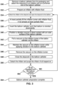
- FIG. 3 a method for purging the balloon catheter 100 of air according to an embodiment hereof is shown.
- the method of FIG. 3 is preferably performed prior to an interventional procedure which utilizes the balloon catheter 100 in situ.
- This method is particularly advantageous for balloon catheters having larger balloons, such as but not limited to a balloon catheter configured as a delivery device for a replacement heart valve, because the method substantially reduces the length of the catheter preparation time by applying the vibration source 226 to expedite bubble/air removal from the balloon catheter as described above.
- the balloon catheter 100 is removed from its packaging.
- the stopcock 222 is attached to the inflation port at the proximal portion 102 of the balloon catheter 100. More particularly, the stopcock 222 is attached to the inflation port of the luer fitting 105 of the hub 104 of the balloon catheter 100.
- the distal portion 106 of the balloon catheter 100 includes the balloon 108 and the inflation lumen 120 of the balloon catheter 100 is in fluid communication with the interior of the balloon 120.
- the inflator 224 is prepared by at least partially filling the inflator 224 with an inflation fluid.
- the inflator 224 is a syringe and the inflation fluid is a radiopaque contrast fluid, or a radiopaque contrast fluid mixed with saline or water.
- Other suitable biocompatible inflation fluids may be utilized.
- the inflator 224 is attached to the stopcock 222 which was previously attached to the inflation port of the luer fitting 105 of the hub 104 of the balloon catheter 100 as described above and the stopcock 222 is opened to the balloon catheter 100.
- the stopcock 222 is opened to the balloon catheter 100, the inflator 224 and the inflation lumen 120 of the balloon catheter 100 are in fluid communication and the inflation lumen 120 of the balloon catheter 100 is sealed with respect to atmosphere.
- the inflator 224 may be attached to the stopcock 222 and then the assembly of the inflator 224 and the stopcock 222 may be simultaneously attached to the inflation port at the proximal portion 102 of the balloon catheter 100.
- the inflation lumen 120 is at least partially filled with the inflation fluid from the inflator 224.
- the inflation fluid may be injected or inserted into the balloon 108 and the inflation lumen 120 of the balloon catheter 100 via the inflator 224 by advancing the plunger of the inflator 224.
- a vacuum may be applied or pulled on the inflation lumen 120 of the balloon catheter 100 via the inflator 224 and then the vacuum may be removed by slowly releasing the plunger of the inflator 224 to a neutral position, thereby at least partially filling the inflation lumen 120 with the inflation fluid from the inflator. More particularly, a user can manually apply or pull a vacuum on the inflation lumen 120 of the balloon catheter 100 by "pulling negative” or retracting the plunger of the inflator 224.
- the inflation fluid within the inflator 224 is drawn into the balloon catheter 100 and the inflation lumen 120 at least partially fills with the inflation fluid. Stated another way, removing the vacuum results in inflation fluid from the inflator 224 being pulled into the balloon catheter 100 such that the inflation lumen 120 and the balloon 108 are filled with the inflation fluid. The inflation fluid is drawn into the inflation lumen 120 and balloon 108 as a result of the pressure changes of the enclosed system.
- the balloon catheter 100 is inverted or positioned in an inverted orientation such that the distal portion 106 including the balloon 108 is oriented below or downwardly relative to the proximal portion 102 of the balloon catheter and the inflator 224 coupled thereto.
- the balloon catheter 100 is positioned in a vertical orientation with its distal end including the balloon 108 disposed vertically below the hub 104 and the inflator 224.
- the balloon catheter 100 is not required to be oriented vertically; the balloon catheter 100 may be oriented at an angle so long as the distal portion 106 thereof including the balloon 108 is oriented below or downwardly relative to the inflator 224.
- the positioning of the inflator 224 above the balloon catheter 100 allows air bubbles to ascend or rise through the column of inflation fluid in the inflation lumen 120 and exit from the balloon catheter 100 via the inflator 224.
- the vibration source 226 is positioned in direct contact with an outer surface of the balloon catheter.
- the vibration source 226 is a handheld tool that is configured to be held by a user.
- the vibration source 226 includes an outer surface configured to be held by a user and includes an inner surface (not shown) that is configured to make direct physical contact with the outer surface of the balloon 108 and/or the outer surface of the outer shaft 110.
- the inner surface of the vibration source 226 may have a shape corresponding to the outer surface of the balloon 108 and/or the outer surface of the outer shaft 110.
- a vacuum is applied or pulled on the inflation lumen 120 of the balloon catheter 100 via the inflator 224. More particularly, a user can manually apply or pull a vacuum on the inflation lumen 120 of the balloon catheter 100 by "pulling negative” or retracting the plunger of the inflator 224. Application of a vacuum results in the evacuation of air from the inflation lumen 120 of the balloon catheter 100. Stated another way, any residual air or gas is purged from the inflation lumen 120 of the balloon catheter 100 and the pressure within the inflation lumen 120 of the balloon catheter 100 is lowered to a pressure lower than atmospheric pressure.
- any residual air or gas is purged from the inflation lumen 120 of the balloon catheter 100 until the pressure in the inflation lumen 120 is between 6.89KPa (1 PSIA) and 82.7 KPa (12 PSIA).
- the stopcock remains in its previous position ("open to the balloon catheter 100") and thereby seals the balloon catheter 100 while the inflator 224 pulls a vacuum on the inflation lumen 120 of the balloon catheter 110.
- the vacuum is maintained on the inflation lumen 120 of the balloon catheter 100 via the inflator 224 while simultaneously applying vibration to the balloon catheter 100 via the vibration source 226.
- the balloon catheter 100 is vibrated via the vibration source 226 while applying the vacuum on the inflation lumen 120 of the balloon catheter 100 to cause air within the balloon 108 of the balloon catheter 100 or air within the inflation lumen 120 of the balloon catheter 100 to move upwards towards the proximal end of the balloon catheter 100 and the inflator 224.
- vibrating the balloon catheter 100 with the vibration source 226 causes any air or bubbles entrapped in the balloon catheter 100 to ascend out of the balloon 108 and inflation lumen 120 until such air or bubbles exit from the balloon catheter 100 and enter into the inflator 224.
- the vacuum is maintained on the inflation lumen 120 of the balloon catheter 100 via the inflator 224 while simultaneously applying vibration to the balloon catheter 100 until no new air or bubbles are seen entering into the inflator 224.
- the vacuum is maintained on the inflation lumen and vibration is simultaneously applied on the balloon catheter for between 15 and 45 seconds.
- the vacuum is maintained on the inflation lumen and vibration is simultaneously applied on the balloon catheter for approximately 30 seconds.
- vibration may also be applied during previous method steps as well. For example, vibration may begin immediately after the vibration source 226 is placed into direct contact with the balloon catheter 100 or the vibration may begin prior to or at the same time as the step 342 when the vacuum is initially pulled or applied to the inflation lumen 120.
- the vibration source 226 is moved or slid along the outer surface of the balloon catheter 100 while vibrating the balloon catheter.
- the vibration source 226 may originally be placed in direct physical contact with the outer surface of the balloon 108.
- the user can move or slide the vibration source 226 onto the outer surface of the outer shaft 110 in conjunction with movement of the air within the balloon catheter 100. Direct contact between the outer surface of the balloon catheter 100 and the vibration source 226 is preferably maintained while the vibration source 226 is moved.
- a step 346 after no new air or bubbles are seen entering into the inflator 224, the vacuum is removed from the inflation lumen 120 of the balloon catheter 100 by slowly releasing the plunger of the inflator 224 to a neutral position. Vibration via the vibration source 226 may continue to be applied during this step, or may be removed.
- a step 348 the stopcock 222 is closed to the balloon catheter 100.
- the stopcock 222 is closed to the balloon catheter 100, the inflator 224 and the inflation lumen 120 of the balloon catheter 100 are no longer in fluid communication.
- the inflation lumen 120 of the balloon catheter 100 remains sealed with respect to atmosphere. At this step of the method, it is no longer required to apply vibration to the balloon catheter 100 via the vibration source 226.
- a step 350 after the stopcock 222 is closed to the balloon catheter, the inflator 224 is detached from the stopcock 222 and purged by advancing the plunger to force the air out of the syringe. Any air that has accumulated in the inflator 224 during the step 344 is released or purged from the inflator 224.
- an operator decides or determines whether the balloon catheter 100 is sufficiently purged of air. For example, the operator may visually inspect the balloon catheter 100 to determine whether any additional air bubbles are still present within the balloon catheter 100. The operator may also make the decision whether the balloon catheter 100 is sufficient purged of air based on an observation of the rate and size of air or bubbles seen entering into the inflator 224 during the step 344. If the rate of air or bubbles was relatively slow and/or the size of the air or bubbles was relatively small, the operator may determine that the balloon catheter 100 is sufficiently purged of air. If the operator determines that the balloon catheter 100 is sufficiently purged of air, the balloon catheter preparation method is considered to be complete at a step 354.
- the inflator 224 would then be reattached to the stopcock 222 and the above-described steps of using the inflator to apply or pull a vacuum on the inflation lumen 120 of the balloon catheter 100 while vibrating the balloon catheter 100 with the vibration source 226 are repeated until the air or bubbles are fully purged from the balloon 108 and the inflation lumen 120. More particularly, the steps 334, 336, 338, 340, 342, 344, 346, 348, and 350 are repeated as necessary until all air is removed from the balloon catheter.
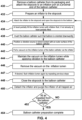
- FIG. 4 illustrates another embodiment hereof in which the inflation lumen 120 may be repeatedly flushed as desired, with vibration being applied while applying vacuum to the balloon catheter, prior to detaching the inflator to purge the inflator of all trapped air. Similar to the method of FIG. 3 , the method of FIG. 4 is preferably performed prior to an interventional procedure which utilizes the balloon catheter 100 in situ. This method is particularly advantageous for balloon catheters having larger balloons, such as but not limited to a balloon catheter configured as a delivery device for a replacement heart valve, because the method substantially reduces the length of the catheter preparation time by applying the vibration source 226 to expedite bubble/air removal from the balloon catheter as described above.
- a step 430 similar to the step 330, the balloon catheter 100 is removed from its packaging.
- the stopcock 222 is attached to the inflation port at the proximal portion 102 of the balloon catheter 100. More particularly, the stopcock 222 is attached to the inflation port of the luer fitting 105 of the hub 104 of the balloon catheter 100.
- the distal portion 106 of the balloon catheter 100 includes the balloon 108 and the inflation lumen 120 of the balloon catheter 100 is in fluid communication with the interior of the balloon 120.
- the inflator 224 is prepared by at least partially filling the inflator 224 with an inflation fluid.
- the inflator 224 is a syringe and the inflation fluid is a radiopaque contrast fluid, or a radiopaque contrast fluid mixed with saline or water.
- Other suitable biocompatible inflation fluids may be utilized.
- a step 434 similar to the step 334, the inflator 224 is attached to the stopcock 222 which was previously attached to the inflation port of the luer fitting 105 of the hub 104 of the balloon catheter 100 as described above and the stopcock 222 is opened to the balloon catheter 100.
- the stopcock 222 is opened to the balloon catheter 100, the inflator 224 and the inflation lumen 120 of the balloon catheter 100 are in fluid communication and the inflation lumen 120 of the balloon catheter 100 is sealed with respect to atmosphere.
- the inflator 224 may be attached to the stopcock 222 and then the assembly of the inflator 224 and the stopcock 222 may be simultaneously attached to the inflation port at the proximal portion 102 of the balloon catheter 100.
- the inflation lumen 120 is at least partially filled with the inflation fluid from the inflator 224.
- the inflation fluid may be injected or inserted into the balloon 108 and the inflation lumen 120 of the balloon catheter 100 via the inflator 224 by advancing the plunger of the inflator 224.
- a vacuum may be applied or pulled on the inflation lumen 120 of the balloon catheter 100 via the inflator 224 and then the vacuum may be removed by slowly releasing the plunger of the inflator 224 to a neutral position, thereby at least partially filling the inflation lumen 120 with the inflation fluid from the inflator. More particularly, a user can manually apply or pull a vacuum on the inflation lumen 120 of the balloon catheter 100 by "pulling negative” or retracting the plunger of the inflator 224.
- the inflation fluid within the inflator 224 is drawn into the balloon catheter 100 and the inflation lumen 120 at least partially fills with the inflation fluid. Stated another way, removing the vacuum results in inflation fluid from the inflator 224 being pulled into the balloon catheter 100 such that the inflation lumen 120 and the balloon 108 are filled with the inflation fluid. The inflation fluid is drawn into the inflation lumen 120 and balloon 108 as a result of the pressure changes of the enclosed system.
- the balloon catheter 100 is inverted or positioned in an inverted orientation such that the distal portion 106 including the balloon 108 is oriented below or downwardly relative to the proximal portion 102 of the balloon catheter and the inflator 224 coupled thereto.
- the balloon catheter 100 is positioned in a vertical orientation with its distal end including the balloon 108 disposed vertically below the hub 104 and the inflator 224.
- the balloon catheter 100 is not required to be oriented vertically; the balloon catheter 100 may be oriented at an angle so long as the distal portion 106 thereof including the balloon 108 is oriented below or downwardly relative to the inflator 224.
- the positioning of the inflator 224 above the balloon catheter 100 allows air bubbles to ascend or rise through the column of inflation fluid in the inflation lumen 120 and exit from the balloon catheter 100 via the inflator 224.
- the vibration source 226 is positioned in direct contact with an outer surface of the balloon catheter.
- the vibration source 226 is a handheld tool that is configured to be held by a user.
- the vibration source 226 includes an outer surface configured to be held by a user and includes an inner surface (not shown) that is configured to make direct physical contact with the outer surface of the balloon 108 and/or the outer surface of the outer shaft 110.
- the inner surface of the vibration source 226 may have a shape corresponding to the outer surface of the balloon 108 and/or the outer surface of the outer shaft 110.
- a vacuum is applied or pulled on the inflation lumen 120 of the balloon catheter 100 via the inflator 224. More particularly, a user can manually apply or pull a vacuum on the inflation lumen 120 of the balloon catheter 100 by "pulling negative” or retracting the plunger of the inflator 224. Application of a vacuum results in the evacuation of air from the inflation lumen 120 of the balloon catheter 100. Stated another way, any residual air or gas is purged from the inflation lumen 120 of the balloon catheter 100 and the pressure within the inflation lumen 120 of the balloon catheter 100 is lowered to a pressure lower than atmospheric pressure.
- any residual air or gas is purged from the inflation lumen 120 of the balloon catheter 100 until the pressure in the inflation lumen 120 is between 6.89 KPA (+ PSIA) and 82.7 KPa (12 PSIA).
- the stopcock 222 remains in its previous position ("open to the balloon catheter 100") and thereby seals the balloon catheter 100 while the inflator 224 pulls a vacuum on the inflation lumen 120 of the balloon catheter 110.
- a step 444 similar to the step 344, the vacuum is maintained on the inflation lumen 120 of the balloon catheter 100 via the inflator 224 while simultaneously applying vibration to the balloon catheter 100 via the vibration source 226.
- the balloon catheter 100 is vibrated via the vibration source 226 while applying the vacuum on the inflation lumen 120 of the balloon catheter 100 to cause air within the balloon 108 of the balloon catheter 100 or air within the inflation lumen 120 of the balloon catheter 100 to move upwards through the column of inflation fluid towards the proximal end of the balloon catheter 100 and the inflator 224.
- vibrating the balloon catheter 100 with the vibration source 226 causes any air or bubbles entrapped in the balloon catheter 100 to ascend out of the balloon 108 and inflation lumen 120 until such air or bubbles exit from the balloon catheter 100 and enter into the inflator 224.
- the user can visually see such air or bubbles in the inflator 224.
- the vacuum is maintained on the inflation lumen 120 of the balloon catheter 100 via the inflator 224 while simultaneously applying vibration to the balloon catheter 100 until no new air or bubbles are seen entering into the inflator 224.
- the vacuum is maintained on the inflation lumen and vibration is simultaneously applied on the balloon catheter for between 15 and 45 seconds.
- the vacuum is maintained on the inflation lumen and vibration is simultaneously applied on the balloon catheter for approximately 30 seconds.
- vibration may also be applied during previous method steps as well. For example, vibration may begin immediately after the vibration source 226 is placed into direct contact with the balloon catheter 100 or the vibration may begin prior to or at the same time as the step 442 when the vacuum is initially pulled or applied to the inflation lumen 120.
- the vibration source 226 is moved or slid along the outer surface of the balloon catheter 100 while vibrating the balloon catheter.
- the vibration source 226 may originally be placed in direct physical contact with the outer surface of the balloon 108.
- the user can move or slide the vibration source 226 onto the outer surface of the outer shaft 110 in conjunction with movement of the air within the balloon catheter 100. Direct contact between the outer surface of the balloon catheter 100 and the vibration source 226 is preferably maintained while the vibration source 226 is moved.
- a step 446 similar to the step 346, after no new air or bubbles are seen entering into the inflator 224, the vacuum is removed from the inflation lumen 120 of the balloon catheter 100 by slowly releasing the plunger of the inflator 224 to a neutral position. Vibration via the vibration source 226 may continue to be applied during this step, or may be removed.
- steps 442, 444, and 446 may be repeated if desired to flush the inflation lumen 120 of the balloon catheter 100 again. More particularly, it may be desired to flush the inflation lumen 120 several times before proceeding to the later method steps of closing and detaching the stopcock 222 and purging the inflator 224 of all trapped air.
- an operator may choose to repeat the steps of pulling a vacuum, maintaining the vacuum while simultaneously applying vibration to the balloon catheter 100, and then removing the vacuum as many times as desired before proceeding to the next method steps.
- a step 448 similar to the step 348, the stopcock 222 is closed to the balloon catheter 100.
- the stopcock 222 is closed to the balloon catheter 100, the inflator 224 and the inflation lumen 120 of the balloon catheter 100 are no longer in fluid communication.
- the inflation lumen 120 of the balloon catheter 100 remains sealed with respect to atmosphere. At this step of the method, it is no longer required to apply vibration to the balloon catheter 100 via the vibration source 226.
- a step 450 similar to the step 350, after the stopcock 222 is closed to the balloon catheter, the inflator 224 is detached from the stopcock 222 and purged by advancing the plunger to force the air out of the syringe. Any air that has accumulated in the inflator 224 during the previous steps is released or purged from the inflator 224.
- an operator decides or determines whether the balloon catheter 100 is sufficiently purged of air. For example, the operator may visually inspect the balloon catheter 100 to determine whether any additional air bubbles are still present within the balloon catheter 100. The operator may also make the decision whether the balloon catheter 100 is sufficient purged of air based on an observation of the rate and size of air or bubbles seen entering into the inflator 224 during the step 444. If the rate of air or bubbles was relatively slow and/or the size of the air or bubbles was relatively small, the operator may determine that the balloon catheter 100 is sufficiently purged of air. If the operator determines that the balloon catheter 100 is sufficiently purged of air, the balloon catheter preparation method is considered to be complete at a step 454.
- the inflator 224 would then be reattached to the stopcock 222 and the above-described steps of using the inflator to apply or pull a vacuum on the inflation lumen 120 of the balloon catheter 100 while vibrating the balloon catheter 100 with the vibration source 226 are repeated until the air or bubbles are fully purged from the balloon 108 and the inflation lumen 120. More particularly, the steps 434, 436, 438, 440, 442, 444, 446, 447, 448, and 450 are repeated as necessary until all air is removed from the balloon catheter.
- the inflator 224 is used to manually pull vacuum as well as to inject or insert inflation fluid into the balloon catheter 100 during the described methods.
- pulling a vacuum with the inflator 224 is not required as shown in the method depicted in FIG. 5 .
- only vibration via the vibration source 224 may be utilized to purge air from the balloon catheter 100.
- the method of FIG. 5 is preferably performed prior to an interventional procedure which utilizes the balloon catheter 100 in situ.
- This method is particularly advantageous for balloon catheters having larger balloons, such as but not limited to a balloon catheter configured as a delivery device for a replacement heart valve, because the method substantially reduces the length of the catheter preparation time by applying the vibration source 226 to expedite bubble/air removal from the balloon catheter as described above.
- a step 530 similar to the step 330, the balloon catheter 100 is removed from its packaging.
- the stopcock 222 is attached to the inflation port at the proximal portion 102 of the balloon catheter 100. More particularly, the stopcock 222 is attached to the inflation port of the luer fitting 105 of the hub 104 of the balloon catheter 100.
- the distal portion 106 of the balloon catheter 100 includes the balloon 108 and the inflation lumen 120 of the balloon catheter 100 is in fluid communication with the interior of the balloon 120.
- the inflator 224 is prepared by at least partially filling the inflator 224 with an inflation fluid.
- the inflator 224 is a syringe and the inflation fluid is a radiopaque contrast fluid, or a radiopaque contrast fluid mixed with saline or water.
- Other suitable biocompatible inflation fluids may be utilized.
- the inflator 224 is attached to the stopcock 222 which was previously attached to the inflation port of the luer fitting 105 of the hub 104 of the balloon catheter 1 00 as described above and the stopcock 222 is opened to the balloon catheter 100.
- the stopcock 222 is opened to the balloon catheter 100, the inflator 224 and the inflation lumen 120 of the balloon catheter 100 are in fluid communication and the inflation lumen 120 of the balloon catheter 100 is sealed with respect to atmosphere.
- the inflator 224 may be attached to the stopcock 222 and then the assembly of the inflator 224 and the stopcock 222 may be simultaneously attached to the inflation port at the proximal portion 102 of the balloon catheter 100.
- the inflation lumen 120 is at least partially filled with the inflation fluid from the inflator 224.
- the inflation fluid may be injected or inserted into the balloon 108 and the inflation lumen 120 of the balloon catheter 100 via the inflator 224 by advancing the plunger of the inflator 224.
- a vacuum may be applied or pulled on the inflation lumen 120 of the balloon catheter 100 via the inflator 224 and then the vacuum may be removed by slowly releasing the plunger of the inflator 224 to a neutral position, thereby at least partially filling the inflation lumen 120 with the inflation fluid from the inflator. More particularly, a user can manually apply or pull a vacuum on the inflation lumen 120 of the balloon catheter 100 by "pulling negative” or retracting the plunger of the inflator 224.
- the inflation fluid within the inflator 224 is drawn into the balloon catheter 100 and the inflation lumen 120 at least partially fills with the inflation fluid. Stated another way, removing the vacuum results in inflation fluid from the inflator 224 being pulled into the balloon catheter 100 such that the inflation lumen 120 and the balloon 108 are filled with the inflation fluid. The inflation fluid is drawn into the inflation lumen 120 and balloon 108 as a result of the pressure changes of the enclosed system.
- the balloon catheter 100 is inverted or positioned in an inverted orientation such that the distal portion 106 including the balloon 108 is oriented below or downwardly relative to the proximal portion 102 of the balloon catheter and the inflator 224 coupled thereto.
- the balloon catheter 100 is positioned in a vertical orientation with its distal end including the balloon 108 disposed vertically below the hub 104 and the inflator 224.
- the balloon catheter 100 is not required to be oriented vertically; the balloon catheter 100 may be oriented at an angle so long as the distal portion 106 thereof including the balloon 108 is oriented below or downwardly relative to the inflator 224.
- the positioning of the inflator 224 above the balloon catheter 100 allows air bubbles to ascend or rise through the column of inflation fluid in the inflation lumen 120 and exit from the balloon catheter 100 via the inflator 224.
- the vibration source 226 is positioned in direct contact with an outer surface of the balloon catheter.
- the vibration source 226 is a handheld tool that is configured to be held by a user.
- the vibration source 226 includes an outer surface configured to be held by a user and includes an inner surface (not shown) that is configured to make direct physical contact with the outer surface of the balloon 108 and/or the outer surface of the outer shaft 110.
- the inner surface of the vibration source 226 may have a shape corresponding to the outer surface of the balloon 108 and/or the outer surface of the outer shaft 110.
- vibration is applied to the balloon catheter 100 via the vibration source 226.
- the balloon catheter 100 is vibrated via the vibration source 226 to cause air within the balloon 108 of the balloon catheter 100 or air within the inflation lumen 120 of the balloon catheter 100 to move upwards towards the proximal end of the balloon catheter 100 and the inflator 224.
- vibrating the balloon catheter 100 with the vibration source 226 causes any air or bubbles entrapped in the balloon catheter 100 to ascend out of the balloon 108 and inflation lumen 120 until such air or bubbles exit from the balloon catheter 100 and enter into the inflator 224.
- the user can visually see such air or bubbles in the inflator 224.
- Vibration is applied to the balloon catheter 100 until no new air or bubbles are seen entering into the inflator 224. For example, vibration is applied on the balloon catheter for between 15 and 45 seconds. In another example, vibration is applied on the balloon catheter for approximately 30 seconds.
- the vibration source 226 is moved or slid along the outer surface of the balloon catheter 100 while vibrating the balloon catheter.
- the vibration source 226 may originally be placed in direct physical contact with the outer surface of the balloon 108.
- the user can move or slide the vibration source 226 onto the outer surface of the outer shaft 110 in conjunction with movement of the air within the balloon catheter 100. Direct contact between the outer surface of the balloon catheter 100 and the vibration source 226 is preferably maintained while the vibration source 226 is moved.
- a step 548 similar to the step 348, the stopcock 222 is closed to the balloon catheter 100.
- the stopcock 222 is closed to the balloon catheter 100, the inflator 224 and the inflation lumen 120 of the balloon catheter 100 are no longer in fluid communication.
- the inflation lumen 120 of the balloon catheter 100 remains sealed with respect to atmosphere. At this step of the method, it is no longer required to apply vibration to the balloon catheter 100 via the vibration source 226.
- a step 550 similar to the step 350, after the stopcock 222 is closed to the balloon catheter, the inflator 224 is detached from the stopcock 222 and purged by advancing the plunger to force the air out of the syringe. Any air that has accumulated in the inflator 224 during the step 544 is released or purged from the inflator 224.
- an operator decides or determines whether the balloon catheter 100 is sufficiently purged of air. For example, the operator may visually inspect the balloon catheter 100 to determine whether any additional air bubbles are still present within the balloon catheter 100. The operator may also make the decision whether the balloon catheter 100 is sufficient purged of air based on an observation of the rate and size of air or bubbles seen entering into the inflator 224 during the step 544. If the rate of air or bubbles was relatively slow and/or the size of the air or bubbles was relatively small, the operator may determine that the balloon catheter 100 is sufficiently purged of air. If the operator determines that the balloon catheter 100 is sufficiently purged of air, the balloon catheter preparation method is considered to be complete at a step 554.
- the inflator 224 would then be reattached to the stopcock 222 and the above-described steps including vibrating the balloon catheter 100 with the vibration source 226 are repeated until the air or bubbles are fully purged from the balloon 108 and the inflation lumen 120. More particularly, the steps 534, 536, 538, 540, 544, 548, and 550 are repeated as necessary until all air is removed from the balloon catheter.
Landscapes
- Health & Medical Sciences (AREA)
- Life Sciences & Earth Sciences (AREA)
- Heart & Thoracic Surgery (AREA)
- Biomedical Technology (AREA)
- Biophysics (AREA)
- Pulmonology (AREA)
- Engineering & Computer Science (AREA)
- Anesthesiology (AREA)
- Child & Adolescent Psychology (AREA)
- Hematology (AREA)
- Animal Behavior & Ethology (AREA)
- General Health & Medical Sciences (AREA)
- Public Health (AREA)
- Veterinary Medicine (AREA)
- Vascular Medicine (AREA)
- Media Introduction/Drainage Providing Device (AREA)
Claims (15)
- Verfahren zum Spülen eines Ballonkatheters (100) von Luft, das Verfahren umfassend die Schritte zum:Einführen eines Aufblasfluids in einen Ballon (108) und ein Aufblaslumen (120) eines Ballonkatheters (100), wobei das Aufblaslumen (120) in Fluidverbindung mit dem Ballon (108) steht;dadurch gekennzeichnet, dass das Verfahren ferner die Schritte umfasst:Positionieren des Ballonkatheters (100) in einer invertierten Ausrichtung mit einem distalen Ende (106) davon, das unterhalb eines proximalen Endes (102) davon angeordnet ist, wobei das distale Ende (106) des Ballonkatheters (100) den Ballon (108) einschließt;Positionieren einer Vibrationsquelle (226) in direktem Kontakt mit einer Außenoberfläche des Ballonkatheters (100); undVibrieren des Ballonkatheters (100) mit der Vibrationsquelle (226), um Luft innerhalb des Ballons (108) des Ballonkatheters (100) oder Luft innerhalb des Aufblaslumens (120) des Ballonkatheters (100) zu veranlassen, sich zu dem proximalen Ende (102) des Ballonkatheters (100) hin nach oben zu bewegen.
- Verfahren nach Anspruch 1, wobei das Verfahren zum Spülen des Ballonkatheters (100) von Luft vor einem interventionellen Vorgang durchgeführt wird.
- Verfahren nach Anspruch 1, ferner umfassend die folgenden Schritte:
Bewegen der Vibrationsquelle (226) entlang der Außenoberfläche des Ballonkatheters (100) während des Vibrierens des Ballonkatheters (100), wobei während des Schritts des Bewegens der Vibrationsquelle (226) ein direkter Kontakt zwischen der Außenoberfläche des Ballonkatheters (100) und der Vibrationsquelle (226) aufrechterhalten wird. - Verfahren nach Anspruch 1, ferner umfassend die folgenden Schritte:Anbringen einer Aufblaseinrichtung (224) an dem proximalen Ende (102) des Ballonkatheters (100); undVerwenden der Aufblaseinrichtung (224), um ein Vakuum in dem Aufblaslumen (120) des Ballonkatheters (100) herzustellen, während der Ballonkatheter (100) mit der Vibrationsquelle (226) vibriert wird.
- Verfahren nach Anspruch 4, wobei die Aufblaseinrichtung (224) eine Spritze ist, die das Aufblasfluid darin aufweist.
- Verfahren nach Anspruch 4, ferner umfassend die folgenden Schritte:Lösen der Aufblaseinrichtung (224) von dem proximalen Ende (102) des Ballonkatheters (100) nach dem Schritt des Verwendens der Aufblaseinrichtung (224), um das Vakuum in dem Aufblaslumen (120) des Ballonkatheters (100) herzustellen; undEntfernen von Luft, die sich in der Aufblaseinrichtung (224) angesammelt hat, von der Aufblaseinrichtung (224), und vorzugsweise ferner umfassend die folgenden Schritte:erneutes Anbringen der Aufblaseinrichtung (224) an dem proximalen Ende (102) des Ballonkatheters (100) nach dem Schritt des Entfernens von Luft, die von der Aufblaseinrichtung (224); undWiederholen des Schritts des Verwendens der Aufblaseinrichtung (224), um ein Vakuum in dem Aufblaslumen (120) des Ballonkatheters (100) herzustellen, während der Ballonkatheter (100) mit der Vibrationsquelle (226) vibriert wird.
- Verfahren nach Anspruch 1, wobei ein Absperrhahn (222) den Ballonkatheter (100) während des Schritts des Verwendens der Aufblaseinrichtung (224) abdichtet, um ein Vakuum in dem Aufblaslumen (120) des Ballonkatheters (100) herzustellen, oder wobei der Ballonkatheter (100) als eine Abgabeeinrichtung für eine Ersatzaortenherzklappe konfiguriert ist.
- Verfahren zum Spülen eines Ballonkatheters (100) von Luft, das Verfahren umfassend die Schritte zum:Einführen eines Aufblasfluids in einen Ballon (108) und ein Aufblaslumen (120) eines Ballonkatheters (100), wobei das Aufblaslumen (120) in Fluidverbindung mit dem Ballon (108) steht;dadurch gekennzeichnet, dass das Verfahren ferner die Schritte umfasst:Positionieren des Ballonkatheters (100) in einer invertierten Ausrichtung mit einem distalen Ende (106) davon, das unterhalb eines proximalen Endes (102) davon angeordnet ist, wobei das distale Ende (106) des Ballonkatheters (100) den Ballon (108) einschließt;Positionieren einer Vibrationsquelle (226) in direktem Kontakt mit einer Außenoberfläche des Ballonkatheters (100);Herstellen eines Vakuums in dem Aufblaslumen (120) des Ballonkatheters (100); undVibrieren des Ballonkatheters (100) mit der Vibrationsquelle (226), während das Vakuum in dem Aufblaslumen (120) des Ballonkatheters (100) hergestellt wird, um eine beliebige Luft innerhalb des Ballons (108) des Ballonkatheters (100) und eine beliebige Luft innerhalb des Aufblaslumens (120) des Ballonkatheters (100) zu veranlassen, sich durch das Aufblasfluid hindurch zu dem proximalen Ende (102) des Ballonkatheters (100) hin nach oben zu bewegen.
- Verfahren nach Anspruch 8, wobei das Verfahren zum Spülen des Ballonkatheters (100) von Luft vor einem interventionellen Vorgang durchgeführt wird.
- Verfahren nach Anspruch 8, ferner umfassend folgenden Schritte:
Bewegen der Vibrationsquelle (226) entlang der Außenoberfläche des Ballonkatheters (100) während des Vibrierens des Ballonkatheters (100), wobei während des Schritts des Bewegens der Vibrationsquelle (226) der direkte Kontakt zwischen der Außenoberfläche des Ballonkatheters (100) und der Vibrationsquelle (226) aufrechterhalten wird. - Verfahren nach Anspruch 8, wobei die Schritte des Einführens des Aufblasfluids in den Ballon (108) und das Aufblaslumen (120) und das Herstellen des Vakuums in dem Aufblaslumen (120) über eine Aufblaseinrichtung (224) durchgeführt werden, die an dem proximalen Ende (102) des Ballonkatheters (100) angebracht ist.
- Verfahren nach Anspruch 11, wobei die Aufblaseinrichtung (224) eine Spritze ist.
- Verfahren nach Anspruch 11, ferner umfassend die folgenden Schritte:Lösen der Aufblaseinrichtung (224) von dem proximalen Ende (102) des Ballonkatheters (100) nach dem Schritt des Vibrierens des Ballonkatheters (100) mit der Vibrationsquelle (226), während das Vakuum in dem Aufblaslumen (120) des Ballonkatheters (100) hergestellt wird; undEntfernen jeglicher Luft, die sich in der Aufblaseinrichtung (224) angesammelt hat, von der Aufblaseinrichtung (224), und vorzugsweise ferner umfassend die folgenden Schritte:erneutes Anbringen der Aufblaseinrichtung (224) an dem proximalen Ende (102) des Ballonkatheters (100) nach dem Schritt des Entfernens jeglicher Luft, die sich in der Aufblaseinrichtung (224) angesammelt hat, von der Aufblaseinrichtung (224); undWiederholen des Verfahrens zum Spülen des Ballonkatheters (100) von Luft, bis alle Luft aus dem Ballonkatheter (100) gespült wird.
- Verfahren nach Anspruch 8, wobei ein Absperrhahn den Ballonkatheter (100) während des Schritts des Herstellens des Vakuums in dem Aufblaslumen (120) des Ballonkatheters (100) abdichtet, oder wobei der Ballonkatheter (100) als eine Abgabeeinrichtung für eine Ersatzaortenherzklappe konfiguriert ist.
- Verfahren zum Spülen eines Ballonkatheters (100) von Luft, das Verfahren umfassend die Schritte zum:Einführen eines Aufblasfluids in einen Ballon (108) und ein Aufblaslumen (120) eines Ballonkatheters (100), wobei das Aufblaslumen (120) in Fluidverbindung mit dem Ballon steht;dadurch gekennzeichnet, dass das Verfahren ferner die Schritte umfasst:Positionieren des Ballonkatheters (100) in einer invertierten Ausrichtung mit einem distalen Ende (106) davon, das unterhalb eines proximalen Endes (102) davon angeordnet ist, wobei das distale Ende (106) des Ballonkatheters (100) den Ballon (108) einschließt;Positionieren einer Vibrationsquelle (226) in direktem Kontakt mit einer Außenoberfläche des Ballonkatheters (100);Vibrieren des Ballonkatheters (100) mit der Vibrationsquelle (226); undHerstellen eines Vakuums in dem Aufblaslumen (120) des Ballonkatheters (100);wobei die Schritte des Vibrierens des Ballonkatheters (100) und des Herstellens des Vakuums gleichzeitig durchgeführt werden, wobei vorzugsweise der Ballonkatheter (100) als eine Abgabeeinrichtung für eine Ersatzaortenherzklappe konfiguriert ist.
Applications Claiming Priority (3)
| Application Number | Priority Date | Filing Date | Title |
|---|---|---|---|
| US201962912179P | 2019-10-08 | 2019-10-08 | |
| US16/940,465 US11878133B2 (en) | 2019-10-08 | 2020-07-28 | Methods of preparing balloon expandable catheters for cardiac and vascular interventions |
| PCT/US2020/053725 WO2021071732A1 (en) | 2019-10-08 | 2020-10-01 | Methods of preparing balloon expandable catheters for cardiac and vascular interventions |
Publications (3)
| Publication Number | Publication Date |
|---|---|
| EP4041364A1 EP4041364A1 (de) | 2022-08-17 |
| EP4041364C0 EP4041364C0 (de) | 2024-05-15 |
| EP4041364B1 true EP4041364B1 (de) | 2024-05-15 |
Family
ID=75273829
Family Applications (1)
| Application Number | Title | Priority Date | Filing Date |
|---|---|---|---|
| EP20793524.8A Active EP4041364B1 (de) | 2019-10-08 | 2020-10-01 | Verfahren zu vorbereitung von ballonexpandierbaren kathetern für herz- und gefässeingriffe |
Country Status (4)
| Country | Link |
|---|---|
| US (2) | US11878133B2 (de) |
| EP (1) | EP4041364B1 (de) |
| CN (1) | CN115279445B (de) |
| WO (1) | WO2021071732A1 (de) |
Families Citing this family (1)
| Publication number | Priority date | Publication date | Assignee | Title |
|---|---|---|---|---|
| US11241561B2 (en) * | 2019-11-21 | 2022-02-08 | Stryker Corporation | Balloon catheter with porous outer member for air purging |
Family Cites Families (60)
| Publication number | Priority date | Publication date | Assignee | Title |
|---|---|---|---|---|
| US1942353A (en) | 1932-11-22 | 1934-01-02 | Berger Kornel | Apparatus for and method of forming internal threads by stamping dies |
| US3248184A (en) | 1963-01-11 | 1966-04-26 | Gen Motors Corp | Shell member and method of manufacture |
| NL6615372A (de) | 1966-10-31 | 1968-05-01 | ||
| US3570014A (en) | 1968-09-16 | 1971-03-16 | Warren D Hancock | Stent for heart valve |
| US3845903A (en) | 1973-08-15 | 1974-11-05 | Dunham Bush Inc | One piece radial vane diffuser and method of manufacturing the same |
| CA1069652A (en) | 1976-01-09 | 1980-01-15 | Alain F. Carpentier | Supported bioprosthetic heart valve with compliant orifice ring |
| DE3325820A1 (de) | 1982-09-27 | 1984-03-29 | Kraftwerk Union AG, 4330 Mülheim | Verfahren zum tiefziehen von blech und vorrichtung zur durchfuehrung dieses verfahrens |
| US4626255A (en) | 1983-09-23 | 1986-12-02 | Christian Weinhold | Heart valve bioprothesis |
| EP0179506B1 (de) | 1984-09-28 | 1989-08-02 | Koninklijke Philips Electronics N.V. | Verfahren und Vorrichtung zum Tiefziehen und Biegen einer Schattenmaske für Farbfernsehbildröhre |
| US4821722A (en) | 1987-01-06 | 1989-04-18 | Advanced Cardiovascular Systems, Inc. | Self-venting balloon dilatation catheter and method |
| US4793351A (en) * | 1987-06-15 | 1988-12-27 | Mansfield Scientific, Inc. | Multi-lumen balloon catheter |
| US5035705A (en) * | 1989-01-13 | 1991-07-30 | Scimed Life Systems, Inc. | Method of purging a balloon catheter |
| EP0379794A1 (de) * | 1989-01-27 | 1990-08-01 | C.R. Bard, Inc. | Schnellentlüftender Ballon-Dilatationskatheter |
| US5489298A (en) | 1991-01-24 | 1996-02-06 | Autogenics | Rapid assembly concentric mating stent, tissue heart valve with enhanced clamping and tissue exposure |
| US5334153A (en) | 1992-10-07 | 1994-08-02 | C. R. Bard, Inc. | Catheter purge apparatus and method of use |
| CA2118886C (en) * | 1993-05-07 | 1998-12-08 | Dennis Vigil | Method and apparatus for dilatation of a stenotic vessel |
| US5904697A (en) | 1995-02-24 | 1999-05-18 | Heartport, Inc. | Devices and methods for performing a vascular anastomosis |
| US5716417A (en) | 1995-06-07 | 1998-02-10 | St. Jude Medical, Inc. | Integral supporting structure for bioprosthetic heart valve |
| US7220275B2 (en) | 1996-11-04 | 2007-05-22 | Advanced Stent Technologies, Inc. | Stent with protruding branch portion for bifurcated vessels |
| EP0850607A1 (de) | 1996-12-31 | 1998-07-01 | Cordis Corporation | Klappenprothese zur Implantation in Körperkanälen |
| US6245102B1 (en) | 1997-05-07 | 2001-06-12 | Iowa-India Investments Company Ltd. | Stent, stent graft and stent valve |
| US6001124A (en) | 1997-10-09 | 1999-12-14 | Vascular Science, Inc. | Oblique-angle graft connectors |
| US6425916B1 (en) | 1999-02-10 | 2002-07-30 | Michi E. Garrison | Methods and devices for implanting cardiac valves |
| EP1194088B1 (de) | 1999-07-02 | 2008-03-12 | Spine Solutions Inc. | Zwischenwirbelimplantat |
| US6494889B1 (en) | 1999-09-01 | 2002-12-17 | Converge Medical, Inc. | Additional sutureless anastomosis embodiments |
| HK1050470A1 (zh) | 1999-09-10 | 2003-06-27 | E. Thorpe Patricia | 用於铬静脉不足的血管内处理 |
| JP3826995B2 (ja) | 2000-02-16 | 2006-09-27 | トヨタ自動車株式会社 | キャリヤの製造方法 |
| US20030208261A1 (en) | 2000-03-03 | 2003-11-06 | Thorpe Patricia E. | Bulbous valve and stent for treating vascular reflux |
| WO2002064195A2 (en) | 2001-02-14 | 2002-08-22 | Acist Medical Systems, Inc. | Catheter fluid control system |
| US7374571B2 (en) | 2001-03-23 | 2008-05-20 | Edwards Lifesciences Corporation | Rolled minimally-invasive heart valves and methods of manufacture |
| US6733525B2 (en) | 2001-03-23 | 2004-05-11 | Edwards Lifesciences Corporation | Rolled minimally-invasive heart valves and methods of use |
| US6649063B2 (en) | 2001-07-12 | 2003-11-18 | Nxstage Medical, Inc. | Method for performing renal replacement therapy including producing sterile replacement fluid in a renal replacement therapy unit |
| US6793678B2 (en) | 2002-06-27 | 2004-09-21 | Depuy Acromed, Inc. | Prosthetic intervertebral motion disc having dampening |
| US20050261719A1 (en) * | 2002-11-25 | 2005-11-24 | Israel Chermoni | Catheter and method of its use |
| AU2003200619B2 (en) * | 2003-02-21 | 2008-06-26 | Japan Electel Inc. | Radiofrequency thermal balloon catheter |
| KR100488673B1 (ko) * | 2003-03-18 | 2005-05-11 | 사타케 슈타로 | 고주파 열풍선 카테터 |
| US7270679B2 (en) | 2003-05-30 | 2007-09-18 | Warsaw Orthopedic, Inc. | Implants based on engineered metal matrix composite materials having enhanced imaging and wear resistance |
| US7267680B2 (en) | 2003-10-08 | 2007-09-11 | David Walter Wright | Anastomosis apparatus and methods of deployment and manufacture |
| DE202004009542U1 (de) | 2004-06-16 | 2004-08-12 | Aesculap Ag & Co. Kg | Zwischenwirbelimplantat |
| ATE438360T1 (de) | 2004-09-08 | 2009-08-15 | Synthes Gmbh | Universal-bandscheibenprothese |
| ITTO20050074A1 (it) | 2005-02-10 | 2006-08-11 | Sorin Biomedica Cardio Srl | Protesi valvola cardiaca |
| US7361192B2 (en) | 2005-04-22 | 2008-04-22 | Doty Keith L | Spinal disc prosthesis and methods of use |
| US20060271161A1 (en) | 2005-05-26 | 2006-11-30 | Boston Scientific Scimed, Inc. | Selective treatment of stent side branch petals |
| FR2888489B1 (fr) | 2005-07-18 | 2008-05-16 | Abbott Spine Sa | Prothese de disque intervertebral munie de moyens d'ancrage |
| EP1991168B1 (de) | 2006-02-16 | 2016-01-27 | Transcatheter Technologies GmbH | Minimalinvasiver herzklappenersatz |
| KR101337707B1 (ko) | 2006-02-23 | 2013-12-06 | 퍼네윌 이노베이션스 인베스트먼트 엘티디. | 추간판 치환물 |
| EP2063817A4 (de) | 2006-09-15 | 2012-04-18 | Pioneer Surgical Technology Inc | Gelenkarthroplastie-vorrichtung mit beweglichen elementen |
| WO2008049048A2 (en) | 2006-10-18 | 2008-04-24 | Graphic Packaging International, Inc. | Tool for forming a three dimensional article or container |
| US7871436B2 (en) | 2007-02-16 | 2011-01-18 | Medtronic, Inc. | Replacement prosthetic heart valves and methods of implantation |
| US7896915B2 (en) | 2007-04-13 | 2011-03-01 | Jenavalve Technology, Inc. | Medical device for treating a heart valve insufficiency |
| US7892332B2 (en) | 2007-10-01 | 2011-02-22 | Baxter International Inc. | Dialysis systems having air traps with internal structures to enhance air removal |
| US20130053693A1 (en) | 2007-12-21 | 2013-02-28 | Indian Wells Medical, Inc. | Method and apparatus for prevention of catheter air intake |
| CA2715448C (en) | 2008-02-25 | 2017-06-13 | Medtronic Vascular Inc. | Infundibular reducer devices |
| US8034099B2 (en) | 2008-03-27 | 2011-10-11 | Medtronic Vascular, Inc. | Stent prosthesis having select flared crowns |
| US8652202B2 (en) | 2008-08-22 | 2014-02-18 | Edwards Lifesciences Corporation | Prosthetic heart valve and delivery apparatus |
| US20100256723A1 (en) | 2009-04-03 | 2010-10-07 | Medtronic Vascular, Inc. | Prosthetic Valve With Device for Restricting Expansion |
| US8500801B2 (en) | 2009-04-21 | 2013-08-06 | Medtronic, Inc. | Stents for prosthetic heart valves and methods of making same |
| JP5731965B2 (ja) * | 2011-12-27 | 2015-06-10 | 有限会社日本エレクテル | 高周波加温バルーンカテーテル |
| CN105188830B (zh) * | 2012-12-28 | 2019-06-07 | 巴德血管外围设备公司 | 通过机械振动球囊的药物传递 |
| CN108371745B (zh) * | 2018-03-16 | 2025-07-25 | 上海心至医疗科技有限公司 | 一种带振动的药物洗脱球囊导管系统 |
-
2020
- 2020-07-28 US US16/940,465 patent/US11878133B2/en active Active
- 2020-10-01 EP EP20793524.8A patent/EP4041364B1/de active Active
- 2020-10-01 WO PCT/US2020/053725 patent/WO2021071732A1/en not_active Ceased
- 2020-10-01 CN CN202080070563.1A patent/CN115279445B/zh active Active
-
2023
- 2023-12-07 US US18/532,090 patent/US20240100307A1/en active Pending
Also Published As
| Publication number | Publication date |
|---|---|
| CN115279445B (zh) | 2025-04-15 |
| EP4041364A1 (de) | 2022-08-17 |
| US20240100307A1 (en) | 2024-03-28 |
| EP4041364C0 (de) | 2024-05-15 |
| WO2021071732A1 (en) | 2021-04-15 |
| US11878133B2 (en) | 2024-01-23 |
| US20210100988A1 (en) | 2021-04-08 |
| CN115279445A (zh) | 2022-11-01 |
Similar Documents
| Publication | Publication Date | Title |
|---|---|---|
| US5035705A (en) | Method of purging a balloon catheter | |
| US7169161B2 (en) | Guidewire having occlusive device and repeatably crimpable proximal end | |
| US4793351A (en) | Multi-lumen balloon catheter | |
| US6932828B2 (en) | Guidewire occlusion system utilizing repeatably inflatable gas-filled occlusive device | |
| JP6959003B2 (ja) | 大動脈用途向きのインフレート可能な閉塞ワイヤ・バルーン | |
| JP5663471B2 (ja) | ステント・グラフト・デリバリー・システム | |
| US10610394B2 (en) | Systems and methods for using perfluorocarbons to remove gases from medical devices | |
| US20060200191A1 (en) | Method and apparatuses for treating an intravascular occlusion | |
| US11278707B2 (en) | Balloon catheter assembly for insertion and positioning therapeutic devices within a vascular system | |
| WO1992011894A1 (en) | Vented dilatation catheter and method for venting | |
| WO2003099352A2 (en) | Methods and apparatus for aspiration and priming of inflatable structures in catheters | |
| US12465730B2 (en) | Balloon catheter with porous outer member for air purging | |
| US20050182437A1 (en) | Guidewire assembly including a repeatably inflatable occlusive balloon on a guidewire ensheathed with a spiral coil | |
| US7615031B2 (en) | Gas inflation/evacuation system incorporating a multiple element valved guidewire assembly having an occlusive device | |
| EP2893907A1 (de) | Einführvorrichtung für eine einführbare medizinische Vorrichtung | |
| KR20220142431A (ko) | 과잉 약물 전달을 최소화하기 위한 방법 및 장치 | |
| US20240100307A1 (en) | Methods of preparing balloon expandable catheters for cardiac and vascular interventions | |
| EP1898986A1 (de) | Ballonangioplastievorrichtung mit distaler schutzmöglichkeit | |
| CN108135716B (zh) | 从医疗设备移除空气的系统和方法 | |
| JP2005508230A (ja) | 繰り返し膨張可能なガス充填膨張素子を採用したガイドワイヤ膨張システム | |
| US7377931B2 (en) | Balloon catheter with self-actuating purging valve | |
| US20040122464A1 (en) | Balloon catheter having a microporous distal tip | |
| US20060089701A1 (en) | In situ molded stent and method and system for delivery |
Legal Events
| Date | Code | Title | Description |
|---|---|---|---|
| STAA | Information on the status of an ep patent application or granted ep patent |
Free format text: STATUS: UNKNOWN |
|
| STAA | Information on the status of an ep patent application or granted ep patent |
Free format text: STATUS: THE INTERNATIONAL PUBLICATION HAS BEEN MADE |
|
| PUAI | Public reference made under article 153(3) epc to a published international application that has entered the european phase |
Free format text: ORIGINAL CODE: 0009012 |
|
| STAA | Information on the status of an ep patent application or granted ep patent |
Free format text: STATUS: REQUEST FOR EXAMINATION WAS MADE |
|
| 17P | Request for examination filed |
Effective date: 20220502 |
|
| AK | Designated contracting states |
Kind code of ref document: A1 Designated state(s): AL AT BE BG CH CY CZ DE DK EE ES FI FR GB GR HR HU IE IS IT LI LT LU LV MC MK MT NL NO PL PT RO RS SE SI SK SM TR |
|
| DAV | Request for validation of the european patent (deleted) | ||
| DAX | Request for extension of the european patent (deleted) | ||
| GRAP | Despatch of communication of intention to grant a patent |
Free format text: ORIGINAL CODE: EPIDOSNIGR1 |
|
| STAA | Information on the status of an ep patent application or granted ep patent |
Free format text: STATUS: GRANT OF PATENT IS INTENDED |
|
| RIC1 | Information provided on ipc code assigned before grant |
Ipc: A61M 25/10 20130101AFI20230526BHEP |
|
| INTG | Intention to grant announced |
Effective date: 20230619 |
|
| GRAJ | Information related to disapproval of communication of intention to grant by the applicant or resumption of examination proceedings by the epo deleted |
Free format text: ORIGINAL CODE: EPIDOSDIGR1 |
|
| STAA | Information on the status of an ep patent application or granted ep patent |
Free format text: STATUS: REQUEST FOR EXAMINATION WAS MADE |
|
| INTC | Intention to grant announced (deleted) | ||
| GRAP | Despatch of communication of intention to grant a patent |
Free format text: ORIGINAL CODE: EPIDOSNIGR1 |
|
| STAA | Information on the status of an ep patent application or granted ep patent |
Free format text: STATUS: GRANT OF PATENT IS INTENDED |
|
| INTG | Intention to grant announced |
Effective date: 20231219 |
|
| GRAS | Grant fee paid |
Free format text: ORIGINAL CODE: EPIDOSNIGR3 |
|
| GRAA | (expected) grant |
Free format text: ORIGINAL CODE: 0009210 |
|
| STAA | Information on the status of an ep patent application or granted ep patent |
Free format text: STATUS: THE PATENT HAS BEEN GRANTED |
|
| AK | Designated contracting states |
Kind code of ref document: B1 Designated state(s): AL AT BE BG CH CY CZ DE DK EE ES FI FR GB GR HR HU IE IS IT LI LT LU LV MC MK MT NL NO PL PT RO RS SE SI SK SM TR |
|
| REG | Reference to a national code |
Ref country code: CH Ref legal event code: EP |
|
| REG | Reference to a national code |
Ref country code: IE Ref legal event code: FG4D |
|
| REG | Reference to a national code |
Ref country code: DE Ref legal event code: R096 Ref document number: 602020031022 Country of ref document: DE |
|
| U01 | Request for unitary effect filed |
Effective date: 20240604 |
|
| U07 | Unitary effect registered |
Designated state(s): AT BE BG DE DK EE FI FR IT LT LU LV MT NL PT SE SI Effective date: 20240613 |
|
| PG25 | Lapsed in a contracting state [announced via postgrant information from national office to epo] |
Ref country code: IS Free format text: LAPSE BECAUSE OF FAILURE TO SUBMIT A TRANSLATION OF THE DESCRIPTION OR TO PAY THE FEE WITHIN THE PRESCRIBED TIME-LIMIT Effective date: 20240915 |
|
| PG25 | Lapsed in a contracting state [announced via postgrant information from national office to epo] |
Ref country code: HR Free format text: LAPSE BECAUSE OF FAILURE TO SUBMIT A TRANSLATION OF THE DESCRIPTION OR TO PAY THE FEE WITHIN THE PRESCRIBED TIME-LIMIT Effective date: 20240515 |
|
| PG25 | Lapsed in a contracting state [announced via postgrant information from national office to epo] |
Ref country code: GR Free format text: LAPSE BECAUSE OF FAILURE TO SUBMIT A TRANSLATION OF THE DESCRIPTION OR TO PAY THE FEE WITHIN THE PRESCRIBED TIME-LIMIT Effective date: 20240816 |
|
| PG25 | Lapsed in a contracting state [announced via postgrant information from national office to epo] |
Ref country code: ES Free format text: LAPSE BECAUSE OF FAILURE TO SUBMIT A TRANSLATION OF THE DESCRIPTION OR TO PAY THE FEE WITHIN THE PRESCRIBED TIME-LIMIT Effective date: 20240515 |
|
| U20 | Renewal fee for the european patent with unitary effect paid |
Year of fee payment: 5 Effective date: 20240919 |
|
| PG25 | Lapsed in a contracting state [announced via postgrant information from national office to epo] |
Ref country code: PL Free format text: LAPSE BECAUSE OF FAILURE TO SUBMIT A TRANSLATION OF THE DESCRIPTION OR TO PAY THE FEE WITHIN THE PRESCRIBED TIME-LIMIT Effective date: 20240515 |
|
| PG25 | Lapsed in a contracting state [announced via postgrant information from national office to epo] |
Ref country code: PL Free format text: LAPSE BECAUSE OF FAILURE TO SUBMIT A TRANSLATION OF THE DESCRIPTION OR TO PAY THE FEE WITHIN THE PRESCRIBED TIME-LIMIT Effective date: 20240515 Ref country code: NO Free format text: LAPSE BECAUSE OF FAILURE TO SUBMIT A TRANSLATION OF THE DESCRIPTION OR TO PAY THE FEE WITHIN THE PRESCRIBED TIME-LIMIT Effective date: 20240815 Ref country code: IS Free format text: LAPSE BECAUSE OF FAILURE TO SUBMIT A TRANSLATION OF THE DESCRIPTION OR TO PAY THE FEE WITHIN THE PRESCRIBED TIME-LIMIT Effective date: 20240915 Ref country code: HR Free format text: LAPSE BECAUSE OF FAILURE TO SUBMIT A TRANSLATION OF THE DESCRIPTION OR TO PAY THE FEE WITHIN THE PRESCRIBED TIME-LIMIT Effective date: 20240515 Ref country code: GR Free format text: LAPSE BECAUSE OF FAILURE TO SUBMIT A TRANSLATION OF THE DESCRIPTION OR TO PAY THE FEE WITHIN THE PRESCRIBED TIME-LIMIT Effective date: 20240816 Ref country code: ES Free format text: LAPSE BECAUSE OF FAILURE TO SUBMIT A TRANSLATION OF THE DESCRIPTION OR TO PAY THE FEE WITHIN THE PRESCRIBED TIME-LIMIT Effective date: 20240515 Ref country code: RS Free format text: LAPSE BECAUSE OF FAILURE TO SUBMIT A TRANSLATION OF THE DESCRIPTION OR TO PAY THE FEE WITHIN THE PRESCRIBED TIME-LIMIT Effective date: 20240815 |
|
| PG25 | Lapsed in a contracting state [announced via postgrant information from national office to epo] |
Ref country code: CZ Free format text: LAPSE BECAUSE OF FAILURE TO SUBMIT A TRANSLATION OF THE DESCRIPTION OR TO PAY THE FEE WITHIN THE PRESCRIBED TIME-LIMIT Effective date: 20240515 |
|
| PG25 | Lapsed in a contracting state [announced via postgrant information from national office to epo] |
Ref country code: RO Free format text: LAPSE BECAUSE OF FAILURE TO SUBMIT A TRANSLATION OF THE DESCRIPTION OR TO PAY THE FEE WITHIN THE PRESCRIBED TIME-LIMIT Effective date: 20240515 Ref country code: SK Free format text: LAPSE BECAUSE OF FAILURE TO SUBMIT A TRANSLATION OF THE DESCRIPTION OR TO PAY THE FEE WITHIN THE PRESCRIBED TIME-LIMIT Effective date: 20240515 |
|
| PG25 | Lapsed in a contracting state [announced via postgrant information from national office to epo] |
Ref country code: SM Free format text: LAPSE BECAUSE OF FAILURE TO SUBMIT A TRANSLATION OF THE DESCRIPTION OR TO PAY THE FEE WITHIN THE PRESCRIBED TIME-LIMIT Effective date: 20240515 |
|
| PG25 | Lapsed in a contracting state [announced via postgrant information from national office to epo] |
Ref country code: SM Free format text: LAPSE BECAUSE OF FAILURE TO SUBMIT A TRANSLATION OF THE DESCRIPTION OR TO PAY THE FEE WITHIN THE PRESCRIBED TIME-LIMIT Effective date: 20240515 Ref country code: SK Free format text: LAPSE BECAUSE OF FAILURE TO SUBMIT A TRANSLATION OF THE DESCRIPTION OR TO PAY THE FEE WITHIN THE PRESCRIBED TIME-LIMIT Effective date: 20240515 Ref country code: RO Free format text: LAPSE BECAUSE OF FAILURE TO SUBMIT A TRANSLATION OF THE DESCRIPTION OR TO PAY THE FEE WITHIN THE PRESCRIBED TIME-LIMIT Effective date: 20240515 Ref country code: CZ Free format text: LAPSE BECAUSE OF FAILURE TO SUBMIT A TRANSLATION OF THE DESCRIPTION OR TO PAY THE FEE WITHIN THE PRESCRIBED TIME-LIMIT Effective date: 20240515 |
|
| REG | Reference to a national code |
Ref country code: DE Ref legal event code: R097 Ref document number: 602020031022 Country of ref document: DE |
|
| PLBE | No opposition filed within time limit |
Free format text: ORIGINAL CODE: 0009261 |
|
| STAA | Information on the status of an ep patent application or granted ep patent |
Free format text: STATUS: NO OPPOSITION FILED WITHIN TIME LIMIT |
|
| 26N | No opposition filed |
Effective date: 20250218 |
|
| REG | Reference to a national code |
Ref country code: CH Ref legal event code: PL |
|
| PG25 | Lapsed in a contracting state [announced via postgrant information from national office to epo] |
Ref country code: MC Free format text: LAPSE BECAUSE OF FAILURE TO SUBMIT A TRANSLATION OF THE DESCRIPTION OR TO PAY THE FEE WITHIN THE PRESCRIBED TIME-LIMIT Effective date: 20240515 |
|
| PG25 | Lapsed in a contracting state [announced via postgrant information from national office to epo] |
Ref country code: CH Free format text: LAPSE BECAUSE OF NON-PAYMENT OF DUE FEES Effective date: 20241031 |
|
| PGFP | Annual fee paid to national office [announced via postgrant information from national office to epo] |
Ref country code: GB Payment date: 20250923 Year of fee payment: 6 |
|
| PG25 | Lapsed in a contracting state [announced via postgrant information from national office to epo] |
Ref country code: IE Free format text: LAPSE BECAUSE OF NON-PAYMENT OF DUE FEES Effective date: 20241001 |
|
| U20 | Renewal fee for the european patent with unitary effect paid |
Year of fee payment: 6 Effective date: 20250923 |
|
| PG25 | Lapsed in a contracting state [announced via postgrant information from national office to epo] |
Ref country code: CY Free format text: LAPSE BECAUSE OF FAILURE TO SUBMIT A TRANSLATION OF THE DESCRIPTION OR TO PAY THE FEE WITHIN THE PRESCRIBED TIME-LIMIT; INVALID AB INITIO Effective date: 20201001 |
|
| PG25 | Lapsed in a contracting state [announced via postgrant information from national office to epo] |
Ref country code: HU Free format text: LAPSE BECAUSE OF FAILURE TO SUBMIT A TRANSLATION OF THE DESCRIPTION OR TO PAY THE FEE WITHIN THE PRESCRIBED TIME-LIMIT; INVALID AB INITIO Effective date: 20201001 |