EP4040890B1 - Verfahren und vorrichtung zur referenzsignalübertragung - Google Patents
Verfahren und vorrichtung zur referenzsignalübertragung Download PDFInfo
- Publication number
- EP4040890B1 EP4040890B1 EP19951969.5A EP19951969A EP4040890B1 EP 4040890 B1 EP4040890 B1 EP 4040890B1 EP 19951969 A EP19951969 A EP 19951969A EP 4040890 B1 EP4040890 B1 EP 4040890B1
- Authority
- EP
- European Patent Office
- Prior art keywords
- frequency domain
- domain resource
- reference signal
- target reference
- ptrs
- Prior art date
- Legal status (The legal status is an assumption and is not a legal conclusion. Google has not performed a legal analysis and makes no representation as to the accuracy of the status listed.)
- Active
Links
Images


Classifications
-
- H—ELECTRICITY
- H04—ELECTRIC COMMUNICATION TECHNIQUE
- H04L—TRANSMISSION OF DIGITAL INFORMATION, e.g. TELEGRAPHIC COMMUNICATION
- H04L5/00—Arrangements affording multiple use of the transmission path
- H04L5/003—Arrangements for allocating sub-channels of the transmission path
- H04L5/0048—Allocation of pilot signals, i.e. of signals known to the receiver
-
- H—ELECTRICITY
- H04—ELECTRIC COMMUNICATION TECHNIQUE
- H04W—WIRELESS COMMUNICATION NETWORKS
- H04W72/00—Local resource management
- H04W72/12—Wireless traffic scheduling
- H04W72/1263—Mapping of traffic onto schedule, e.g. scheduled allocation or multiplexing of flows
-
- H—ELECTRICITY
- H04—ELECTRIC COMMUNICATION TECHNIQUE
- H04L—TRANSMISSION OF DIGITAL INFORMATION, e.g. TELEGRAPHIC COMMUNICATION
- H04L5/00—Arrangements affording multiple use of the transmission path
- H04L5/003—Arrangements for allocating sub-channels of the transmission path
- H04L5/0032—Distributed allocation, i.e. involving a plurality of allocating devices, each making partial allocation
- H04L5/0035—Resource allocation in a cooperative multipoint environment
-
- H—ELECTRICITY
- H04—ELECTRIC COMMUNICATION TECHNIQUE
- H04L—TRANSMISSION OF DIGITAL INFORMATION, e.g. TELEGRAPHIC COMMUNICATION
- H04L5/00—Arrangements affording multiple use of the transmission path
- H04L5/003—Arrangements for allocating sub-channels of the transmission path
- H04L5/0048—Allocation of pilot signals, i.e. of signals known to the receiver
- H04L5/0051—Allocation of pilot signals, i.e. of signals known to the receiver of dedicated pilots, i.e. pilots destined for a single user or terminal
-
- H—ELECTRICITY
- H04—ELECTRIC COMMUNICATION TECHNIQUE
- H04L—TRANSMISSION OF DIGITAL INFORMATION, e.g. TELEGRAPHIC COMMUNICATION
- H04L5/00—Arrangements affording multiple use of the transmission path
- H04L5/0091—Signalling for the administration of the divided path, e.g. signalling of configuration information
- H04L5/0094—Indication of how sub-channels of the path are allocated
-
- H—ELECTRICITY
- H04—ELECTRIC COMMUNICATION TECHNIQUE
- H04W—WIRELESS COMMUNICATION NETWORKS
- H04W16/00—Network planning, e.g. coverage or traffic planning tools; Network deployment, e.g. resource partitioning or cells structures
- H04W16/24—Cell structures
- H04W16/28—Cell structures using beam steering
-
- H—ELECTRICITY
- H04—ELECTRIC COMMUNICATION TECHNIQUE
- H04W—WIRELESS COMMUNICATION NETWORKS
- H04W72/00—Local resource management
- H04W72/04—Wireless resource allocation
- H04W72/044—Wireless resource allocation based on the type of the allocated resource
- H04W72/0446—Resources in time domain, e.g. slots or frames
-
- H—ELECTRICITY
- H04—ELECTRIC COMMUNICATION TECHNIQUE
- H04W—WIRELESS COMMUNICATION NETWORKS
- H04W72/00—Local resource management
- H04W72/04—Wireless resource allocation
- H04W72/044—Wireless resource allocation based on the type of the allocated resource
- H04W72/0453—Resources in frequency domain, e.g. a carrier in FDMA
Definitions
- This disclosure relates to the field of communication technologies, and in particular, to a reference signal transmission method and an apparatus and to a reference signal reception method and apparatus.
- a next-generation 5G communication system is shifting to a higher millimeter wave frequency.
- a millimeter wave device is severely affected by phase noise.
- the next-generation 5G communication system may use a phase tracking reference signal (phase tracking reference signal, PTRS) to perform channel estimation to estimate the effect of the phase noise on a signal and partially compensates for signal distortion caused by the phase noise.
- PTRS phase tracking reference signal
- the PTRS is mapped only to a time-frequency resource occupied by a physical downlink shared channel (physical downlink shared channel, PDSCH), and is mapped by using a specific time domain density and a specific frequency domain density.
- a plurality of stations may support transmission of a same PDSCH, and transmission paths of various stations vary greatly. Therefore, different QCL assumptions are used for data and reference signals such as DMRSs transmitted by various stations.
- the QCL assumption is used to indicate a large-scale parameter used for channel estimation, and further, the large-scale parameter is used to receive a reference signal such as a PTRS or a DMRS, to perform channel estimation.
- a reference signal such as a PTRS or a DMRS
- a time domain density and a frequency domain density used for the PTRS are still determined by using a mechanism similar to that used in a single-station scenario, that is, determined based on total frequency domain resources (namely, scheduled time-frequency resources) occupied by the PDSCH, PTRSs corresponding to various QCL assumptions are sparsely distributed, resulting in inaccurate phase estimation and poor transmission performance.
- Document XP051299892 SAMSUNG: "On DL PTRS design", 3GPP DRAFT) discusses DL PTRS design.
- the observations and proposals are as follows: The number of DL PT-RS ports depends on the number of oscillators at gNB; NR supports pre-defined PT-RS allocation; For multi-TRP scenario, NR should be supported PT-RS information exchange between TRPs. For orthogonal multiplexing, ZP PT-RS should be supported by using the PT-RS information; For multi-TRP scenario, NR should be supported fall-back mode PTRS configuration according to backhaul link performance; For MU-MIMO, both non-orthogonal multiplexing/orthogonal multiplexing between PT-RS and data should be supported.
- ZP PT-RS For orthogonal multiplexing, ZP PT-RS should be supported; NR should inform UE the QCL relationship between PT-RS and DMRS port group by higher layer signalling with parameter sets which configures QCL association between PT-RS and DMRS port group; and Association between one PTRS port and one DMRS port per DMRS port group should be configurable.
- Document WO 2018/171792 A1 relates to a reference signal transmission method which includes the method steps of: sending, by a terminal, a first reference signal and a second reference signal; and correspondingly, receiving, by a network device, the first reference signal and the second reference signal, where the first reference signal is mapped to a plurality of symbols and is used for estimation of channel state information, the second reference signal is mapped to at least two of the plurality of symbols and is used for phase tracking, and a subcarrier to which the second reference signal is mapped on one of the at least two symbols has a same frequency-domain location as a subcarrier to which the second reference signal is mapped on the rest of the at least two symbols.
- DocumentXP051338980 SPREADTRUM COMMUNICATIONS: "Considerations onPT-RS for CP-OFDM", 3GPP DRAFT
- PT-RS PT-RS port definition, association, and the pattern, wherein the interference issue in MU-MIMO is considered.
- This document also presents the indication of DMRS grouping for PT-RS association.
- scheduled frequency domain resources include a first frequency domain resource and a second frequency domain resource.
- a receive end may determine a frequency domain density K of a target reference signal based on a quantity M RB of frequency domain resources; determine, based on the frequency domain density K, a third frequency domain resource that carries the target reference signal in the first frequency domain resource and a fourth frequency domain resource that carries the target reference signal in the second frequency domain resource.
- the first frequency domain resource is associated with a first QCL assumption
- the second frequency domain resource is associated with a second QCL assumption.
- the receive end may receive, by using the first QCL assumption, the target reference signal carried on the third frequency domain resource, and/or receive, by using the second QCL assumption, the target reference signal carried on the fourth frequency domain resource.
- a quantity M RB of frequency domain resources is greater than zero and less than N RB , and N RB is a quantity of scheduled frequency domain resources.
- the frequency domain density K determined by using M RB in the reference signal transmission method is small. Because the frequency domain density K means that a target reference signal is mapped once at an interval of K frequency domain resource blocks, smaller K indicates a denser target reference signal carried on a frequency domain resource. In this way, accuracy of channel estimation can be improved.
- a target reference signal port corresponding to the target reference signal carried on the third frequency domain resource is associated with a DMRS port corresponding to a demodulation reference signal DMRS carried on the first frequency domain resource
- a target reference signal port corresponding to the target reference signal carried on the fourth frequency domain resource is associated with a DMRS port corresponding to a DMRS carried on the second frequency domain resource.
- the determining, based on the frequency domain density K, a third frequency domain resource that carries the target reference signal in the first frequency domain resource and a fourth frequency domain resource that carries the target reference signal in the second frequency domain resource includes: mapping the target reference signal once starting from a reference frequency domain resource block in the scheduled frequency domain resources at an interval of K frequency domain resource blocks, to obtain frequency domain resource blocks that carry the target reference signal; and selecting a frequency domain resource block belonging to the first frequency domain resource as the third frequency domain resource from the frequency domain resource blocks that carry the target reference signal; and/or selecting a frequency domain resource block belonging to the second frequency domain resource as the fourth frequency domain resource from the frequency domain resource blocks that carry the target reference signal.
- mapping the target reference signal once at an interval of K frequency domain resource blocks indicates that the reference frequency domain resource block is used as a start position, and the frequency domain resource blocks that carry the target reference signal are obtained at the interval of K frequency domain resource blocks until the last frequency domain resource block occupied by a shared channel.
- mapping the target reference signal once at an interval of K frequency domain resource blocks indicates that the reference frequency domain resource block is used as a start position, and the frequency domain resource blocks that carry the target reference signal are obtained at an interval of K frequency domain resource blocks until the last frequency domain resource block occupied by a shared channel.
- the determining, based on the frequency domain density K, a third frequency domain resource that carries the target reference signal in the first frequency domain resource and/or a fourth frequency domain resource that carries the target reference signal in the second frequency domain resource includes: mapping a PTRS once starting from a reference frequency domain resource block in the first frequency domain resource at an interval of K frequency domain resource blocks, to obtain frequency domain resource blocks that carry the target reference signal as the third frequency domain resource; and mapping a PTRS once starting from a reference frequency domain resource block in the second frequency domain resource at an interval of K frequency domain resource blocks, to obtain frequency domain resource blocks that carry the target reference signal as the fourth frequency domain resource.
- mapping is performed starting from the reference frequency domain resource block in the entire scheduled frequency domain resources for determining.
- mapping is performed starting from the reference frequency domain resource block in the first frequency domain resource to determine the third frequency domain resource, and mapping is performed starting from the reference frequency domain resource block in the second frequency domain resource to determine the fourth frequency domain resource.
- frequency domain resources associated with the QCL assumptions are not consecutive, this helps avoid a case in which some frequency domain resources associated with the QCL assumptions do not carry the target reference signal.
- the target reference signal is a reference signal used to perform channel estimation or used to assist the demodulation reference signal DMRS in performing channel estimation.
- the target reference signal includes a phase tracking reference signal PTRS.
- the target reference signal is associated with the DMRS.
- this disclosure further provides a reference signal transmission method.
- scheduled frequency domain resources include a first frequency domain resource and a second frequency domain resource, the first frequency domain resource is associated with a first QCL assumption, and the second frequency domain resource is associated with a second QCL assumption.
- a PTRS is mapped to a frequency domain resource associated with the QCL assumption.
- a method for determining a frequency domain density K is the same as that in the first aspect, and details are not described herein again.
- the target reference signal may be received by using the first QCL assumption, and/or a channel estimation result of the target reference signal may be used to assist in receiving the DMRS carried on the first frequency domain resource; and one or more frequency domain resource blocks that are obtained by mapping the target reference signal once starting from a reference frequency domain resource block in the first frequency domain resource at an interval of K frequency domain resource blocks are used as a frequency domain resource that carries the target reference signal.
- the target reference signal may be received by using the second QCL assumption, and/or a channel estimation result of the target reference signal may be used to assist in receiving the DMRS carried on the first frequency domain resource; and one or more frequency domain resource blocks that are obtained by mapping the target reference signal once starting from a reference frequency domain resource block in the second frequency domain resource at an interval of K frequency domain resource blocks are used as a frequency domain resource that carries the target reference signal.
- the reference signal transmission method can specify a transmission rule of the target reference signal, to avoid a problem that transmission performance is affected due to an unclear rule.
- a target reference signal carried on the scheduled frequency domain resources has one QCL assumption
- the target reference signal is mapped to frequency domain resources associated with two QCL assumptions, but one of the QCL assumptions is used for receiving the target reference signal.
- a phase estimation result of the target reference signal may be shared with the two QCL assumptions.
- a manner in which the target reference signal is mapped to the scheduled frequency domain resources and the frequency domain density K of the target reference signal may be determined based on the scheduled frequency domain resources.
- a manner of receiving the target reference signal is receiving, by using the first QCL assumption or the second QCL assumption, the target reference signal carried on the scheduled frequency domain resources. Further, a channel estimation result based on a PTRS may be used to separately assist in receiving a DMRS carried on the first frequency domain resource and receiving a DMRS carried on the second frequency domain resource.
- the reference signal transmission method can specify a transmission rule of the target reference signal, to avoid a problem that channel estimation performance is affected due to an unclear rule.
- different QCL assumptions are used to receive data and DMRSs on a same time-frequency domain resource, and the data and the DMRSs corresponding to the different QCL assumptions correspond to different ports, or the different QCL assumptions correspond to different CDM groups of DMRSs.
- a target reference signal on the time-frequency domain resource is limited to be received by using one QCL assumption.
- one port is configured for the target reference signal, and a target reference signal port is associated with a corresponding QCL assumption on the time-frequency resource.
- the technical solutions in this disclosure can be specifically applied to various communication systems.
- the technical solutions in this disclosure may be further applied to a future network, such as a 5G system or a 6G system, which may also be referred to as a new radio (new radio, NR) system, and may also be applied to a device-to-device (device-to-device, D2D) system, a machine-to-machine (machine-to-machine, M2M) system, and the like.
- FIG. 1 is a schematic diagram of an architecture of a communication system according to an example of this disclosure.
- the communication system may include but is not limited to one network device and one terminal device.
- a quantity and forms of devices shown in FIG. 1 are used as an example and do not constitute a limitation on this example of this disclosure.
- two or more network devices and two or more terminal devices may be included.
- the communication system shown in FIG. 1 is described by using an example in which there are two network devices and the two network devices can serve a same terminal device.
- a transmission reception point TRP is used as an example of the network device
- a mobile phone is used as an example of the terminal device.
- the network device may be a device that has a wireless transceiver function or a chip that can be disposed in the device.
- the network device includes but is not limited to an evolved NodeB (evolved NodeB, eNB), a radio network controller (radio network controller, RNC), a NodeB (NodeB, NB), a network device controller (base station controller, BSC), a network device transceiver station (base transceiver station, BTS), a home network device (for example, a home evolved NodeB, or a home NodeB, HNB), a baseband unit (baseband unit, BBU), an access point (access point, AP) in a wireless fidelity (wireless fidelity, WI-FI) system, a wireless relay node, a wireless backhaul node, a transmission point (transmission and reception point (TRP) or transmission point (TP)), and the like; or may be a device used in a 5G system, a 6G system, or even
- the gNB or the transmission point may include a centralized unit (centralized unit, CU), a distributed unit (DU, distributed unit), and the like.
- the gNB or the transmission point may further include a radio unit (radio unit, RU).
- the CU implements some functions of the gNB or the transmission point
- the DU implements some functions of the gNB or the transmission point.
- the CU implements functions of radio resource control (radio resource control, RRC) and packet data convergence protocol (packet data convergence protocol, PDCP) layers
- the DU implements functions of radio link control (radio link control, RLC), media access control (media access control, MAC), and physical (physical, PHY) layers.
- the network device may be a CU node, a DU node, or a device including the CU node and the DU node.
- the CU may be classified as a network device in an access network RAN, or the CU may be classified as a network device in a core network (core network, CN). This is not limited herein.
- the terminal device may also be referred to as user equipment (user equipment, UE), an access terminal, a user unit, a user station, a mobile station, a remote station, a remote terminal, a mobile device, a user terminal, a user agent, or a user apparatus, and may be used in 5G, 6G, and even 7G systems.
- user equipment user equipment
- UE user equipment
- the terminal device in examples of this disclosure may be a mobile phone (mobile phone), a tablet computer (Pad), a computer having a wireless transceiver function, a virtual reality (virtual reality, VR) terminal device, an augmented reality (augmented reality, AR) terminal device, a wireless terminal in industrial control (industrial control), a wireless terminal in self driving (self driving), a wireless terminal in remote medical (remote medical), a wireless terminal in a smart grid (smart grid), a wireless terminal in transportation safety (transportation safety), a wireless terminal in a smart city (smart city), a wireless terminal in a smart home (smart home), a wireless terminal in V2X vehicle to everything, an RSU of a wireless terminal type, or the like.
- a virtual reality (virtual reality, VR) terminal device an augmented reality (augmented reality, AR) terminal device
- a wireless terminal in industrial control industrial control
- a wireless terminal in self driving self driving
- a wireless terminal in remote medical remote medical
- a resource in a communication system is divided into a plurality of symbols in terms of time, for example, a plurality of orthogonal frequency division multiplexing (Orthogonal Frequency Division Multiple, OFDM) symbols.
- the time domain resource block may be referred to as a time unit.
- the time domain resource block may be one or more radio frames, one or more subframes, one or more slots, one or more mini-slots (mini-slots), one or more orthogonal frequency division multiplexing (orthogonal frequency division multiplexing, OFDM) symbols, a discrete Fourier transform spread orthogonal frequency division multiplexing (discrete Fourier transform spread spectrum orthogonal frequency division multiplexing, DFT-s-OFDM) symbol, or a time window formed by a plurality of frames or subframes, for example, a system information (system information, SI) window.
- SI system information
- the frequency domain resource block may be referred to as a frequency domain unit.
- the frequency domain resource block may be one or more resource blocks (resource blocks, RBs) or one or more subcarriers.
- resource blocks resource blocks, RBs
- one RB includes 12 subcarriers.
- One subcarrier in one RB in frequency domain and one OFDM symbol in time domain form one resource element (Resource Element, RE).
- Positions, a quantity, and the like of scheduled frequency domain resources may be indicated by a frequency domain resource allocation (frequency domain resource allocation, FDRA) field.
- FDRA frequency domain resource allocation
- an entire system bandwidth or a bandwidth part BWP is divided at a granularity of RB groups in a bitmap manner for the field, and each resource set at the granularity of RB groups corresponds to one bit in a bitmap, where a bit in the bitmap is set to 0, indicating that a corresponding RB group is not scheduled, and a bit in the bitmap is set to 1, indicating that a corresponding RB group is scheduled.
- a size of the RB group may be one or more RBs.
- the FDRA field may further indicate a frequency domain start position and a frequency domain size that are occupied by scheduled data.
- Positions, a quantity, and the like of scheduled time domain resources may be indicated by a time domain resource allocation (time domain resource allocation, TDRA) field.
- TDRA time domain resource allocation
- the field indicates a position of a slot or a subframe occupied by the scheduled data, and may be a relative position based on a DCI detection slot or subframe, or an absolute position based on a slot or a subframe defined by a system
- the scheduled frequency domain resources may be frequency domain resources occupied by a scheduled shared channel. For example, 8 RBs are occupied by scheduling a PDSCH by a base station, that is, the scheduled frequency domain resources are 8 RBs, or a quantity of scheduled frequency domain resources is 8. In this specification, the quantity of scheduled frequency domain resources is equal to a quantity of frequency domain resource blocks included in the scheduled frequency domain resources.
- the scheduled time domain resources may be time domain resources occupied by a shared channel.
- the base station schedules 10 symbols for the PDSCH, that is, the scheduled time domain resources are 10 symbols, or a quantity of scheduled time domain resources is 10.
- the quantity of scheduled time domain resources is equal to a quantity of time domain resource blocks included in the scheduled time domain resources.
- the scheduled frequency domain resources and the scheduled time domain resources are indicated by using downlink control information (downlink control information, DCI) or by using RRC signaling.
- precoding resource group PRG
- RBs in the scheduled frequency domain resources are divided into a plurality of RB groups at a granularity of the PRG, and a quantity of RBs included in each RB group is a value of the PRG.
- Precoding (precoding) manners of data, a target reference signal, and the like delivered in an RB group are the same.
- a PRG indication is a wideband (wideband), all RBs in the scheduled frequency domain resources are divided into one group, and a same precoding manner is used for DMRSs and corresponding data transmitted in different RBs on the scheduled frequency domain resources.
- a PRG indication may alternatively be 2 or 4, indicating that one group is obtained at an interval of 2 RBs or 4 RBs, and a same precoding manner is used for data carried in different RBs in an RB group.
- the target reference signal (target resource signal, target RS) is used to perform channel estimation or used to assist a demodulation reference signal (decoding modulation resource signal, DMRS) in performing channel estimation.
- the target reference signal is used to estimate a channel-related parameter, for example, phase estimation, phase tracking, or phase estimation.
- a phase tracking reference signal phase tracking reference signal, PTRS is used to assist the DMRS in performing channel estimation.
- the target reference signal is mapped to a time-frequency resource occupied by a shared channel.
- the target reference signal is simultaneously scheduled.
- the target reference signal is mapped to a time domain resource occupied by the shared channel based on a time domain density L and a reference time domain resource block.
- the time domain resource that carries the PTRS is one or more time domain resource blocks that are obtained by mapping the PTRS once at an interval of L time domain resource blocks starting from the reference time domain resource block in the time domain resources occupied by the shared channel.
- mapping the PTRS once at an interval of L time domain resource blocks is that the reference time domain resource block is used as a start position, and time domain resource blocks that carry the PTRS are obtained at the interval of L time domain resource blocks until the last time domain resource block occupied by the shared channel.
- a second understanding of mapping the PTRS once at an interval of L time domain resource blocks is that the reference time domain resource block is used as a start position, and time domain resource blocks that carry the PTRS are obtained at an interval of L time domain resource blocks until the last time domain resource block occupied by the shared channel.
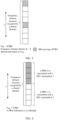
- a time domain resource occupied by a shared channel is 8 symbols from the 3 rd symbol to the 10 th symbol in a slot.
- a reference time domain resource block and a time domain resource block are in a unit of one symbol. Because a DMRS occupies the first N symbols of the time domain resource, for example, N is equal to 1 or 2, that is, the 3 rd symbol or the 4 th symbol in the slot, a PTRS may occupy an (N+1) th symbol and the following symbols of the time domain resource, that is, the 4 th symbol or the 5 th symbol in the slot and the following symbols.
- an offset of a time domain position to which the PTRS is mapped relative to the reference time domain resource block is Lxi, that is, the time domain position to which the PTRS is mapped is i 0 +Lxi, where i may be 0, 1, 2, ..., and the time domain resource to which the PTRS is mapped is as follows: Starting from the 4 th symbol in the slot, the PTRS is mapped once at an interval of two symbols, and obtained symbols carrying the PTRS are respectively the 4 th symbol, the 6 th symbol, the 8 th symbol, and the 10 th symbol in the slot.
- a frequency domain resource occupied by the target reference signal in a frequency domain resource occupied by the shared channel may be determined based on a frequency domain density K and a reference frequency domain resource block.
- the frequency domain resource that carries the PTRS is one or more frequency domain resource blocks that are obtained by mapping the PTRS once at an interval of K frequency domain resource blocks starting from the reference frequency domain resource block in the frequency domain resource occupied by the shared channel.
- a first understanding of "mapping the PTRS once at an interval of K frequency domain resource blocks" is that the reference frequency domain resource block is used as a start position, and frequency domain resource blocks that carry the PTRS are obtained at the interval of K frequency domain resource blocks until the last frequency domain resource block occupied by the shared channel.
- K frequency domain resource blocks are spaced between two adjacent frequency domain resources used to carry the PTRS, that is, the reference frequency domain resource block carries the PTRS, and a frequency domain position to which the PTRS is mapped other than the reference frequency domain resource block is j 0 +K*j+1, where j 0 is a position of the reference frequency domain resource block, K is the frequency domain density, and j may be 1, 2, ....
- the frequency domain resource block that carries the PTRS is one or more frequency domain resource blocks that are obtained by mapping the PTRS once at an interval of K frequency domain resource blocks starting from the reference frequency domain resource block in the frequency domain resource occupied by the shared channel, that is, the reference frequency domain resource block carries the PTRS, and a frequency domain position to which the PTRS is mapped other than the reference frequency domain resource block is j 0 +K*j+1, where j is a position of the reference frequency domain resource block, K is the frequency domain density, and j may be 1, 2, ....
- the frequency domain resource that carries the PTRS is the 1 st RB and the 6 th RB in the frequency domain resource occupied by the shared channel.
- a second understanding of "mapping the PTRS once at an interval of K frequency domain resource blocks" is that the reference frequency domain resource block is used as a start position, and frequency domain resource blocks that carry the PTRS are obtained at an interval of K frequency domain resource blocks until the last frequency domain resource block occupied by the shared channel.
- an offset of a frequency domain position to which the PTRS is mapped relative to the reference frequency domain resource block is K*j, where j may be 0, 1, 2, ....
- the frequency domain resource that carries the PTRS is the 1 st RB and the 5 th RB in the frequency domain resource occupied by the shared channel.
- a subcarrier occupied by the PTRS may be determined from the frequency domain resource block that carries the PTRS.
- the frequency domain resource block is one RB.
- the PTRS occupies one subcarrier in one RB, and a position of the subcarrier is determined based on an index number (DMRS port number for short) of a DMRS port associated with the PTRS and a subcarrier position offset.
- DMRS port number for short an index number of a DMRS port associated with the PTRS and a subcarrier position offset.
- k ref RE indicates an offset between a subcarrier occupied by a PTRS and a start subcarrier in an RB, and is referred to as a resource element offset (resource element offset) or a subcarrier position offset for short.
- the subcarrier occupied by the PTRS is one subcarrier in subcarrier index numbers 0, 2, 6, and 8 in the frequency domain resource blocks that carry the PTRS.
- Table 1 PTRS subcarrier position offset DMRS port (DM-RS antenna port) p k ref RE DMRS configuration type (Configuration type) 1 DM-RS configuration type 2 resourceElementOffset resourceElementOffset 00 01 10 11 00 01 10 11 1000 0 2 6 8 0 1 6 7 1001 2 4 8 10 1 6 7 0 1002 1 3 7 9 2 3 8 9 1003 3 5 9 11 3 8 9 2 1004 - - - - 4 5 10 11 1005 - - - - 5 10 11 4
- a terminal device needs to perform channel estimation based on a DMRS, a PTRS, and the like, and receive corresponding data by using a channel estimation result, thereby improving data receiving performance.
- the QCL assumption is used to indicate the large-scale parameters.
- the QCL assumption includes one or more of the following parameters: an angle of arrival (angle of arrival, AoA), a dominant (Dominant) angle of arrival AoA, an average angle of arrival, a power angular spectrum (power angular spectrum, PAS) of the angle of arrival, an angle of departure (angle of departure, AoD), a dominant angle of departure, an average angle of departure, a power angular spectrum of the angle of departure, terminal transmit beamforming, terminal receive beamforming, spatial channel correlation, base station transmit beamforming, base station receive beamforming, an average channel gain, an average channel delay (average delay), delay spread (delay spread), Doppler spread (Doppler spread), a Doppler shift (Doppler shift), spatial receive parameters (spatial Rx parameters), and the like.
- the QCL assumption includes one or more of the following types of large-scale parameters:
- a QCL assumption indication manner is as follows: A to-be-received reference signal is associated with a reference signal (reference RS), so that a large-scale parameter obtained by using the reference signal may be used to process the to-be-received RS.
- the to-be-received reference signal may be a DMRS
- the DMRS may be associated with a measurement reference signal to indicate that the two signals have a QCL type A and type D association relationship. Therefore, information about the QCL type A and the type D may be obtained by using the measurement reference signal, and is used to assist in receiving the DMRS.
- the to-be-received reference signal may be a DMRS, and the DMRS may be associated with a PTRS to indicate that the two signals have a QCL type A and type D association relationship. Therefore, information about the QCL type A and the type D may be obtained by receiving the DMRS, and is used to assist in receiving the PTRS.
- the to-be-received reference signal may be a DMRS, and the DMRS may be associated with a PTRS to indicate that the two signals have a QCL type B association relationship. Therefore, information about the QCL type B may be obtained by using the DMRS, to assist in receiving the PTRS.
- the to-be-received reference signal may be a DMRS
- the DMRS may be associated with a PTRS to indicate that the two signals have a QCL type B association relationship. Therefore, information about the QCL type B may be obtained by using the PTRS, to assist in receiving the DMRS.
- DCI includes a transmission configuration indication (transmission configuration indication, TCI) field
- TCI field indicates a QCL assumption used for a DMRS carried on scheduled time-frequency resources.
- TCI field may also be referred to as a QCL assumption associated with the scheduled time-frequency resources. That is, a time-frequency resource is associated with a QCL assumption, which may indicate that data and a DMRS that are carried on the time-frequency resource are received by using the QCL assumption.
- a target reference signal other than the DMRS is used to assist the DMRS in performing channel estimation.
- a phase estimation result of the PTRS may be used to adjust some parameters in the QCL assumption used for the DMRS carried on the time-frequency resource. Therefore, the PTRS is associated with the DMRS.
- an estimation result of the PTRS may be used to adjust some large-scale parameters in the QCL assumption used for the DMRS, for example, QCL types B, and the PTRS may be received by using the QCL assumption used for the DMRS.
- the PTRS is received by using QCL types A and QCL types D in the QCL assumption.
- large-scale parameters used for receiving the PTRS for example, the QCL type A, type B, and type D, are obtained from receiving of the DMRS.
- the time-frequency resource described in this specification may be a time domain resource, a frequency domain resource, or a time domain resource and a frequency domain resource. Therefore, in this specification, a scenario to which all the three cases are applicable is collectively referred to as a time-frequency resource.
- the time-frequency resource is associated with the QCL assumption, indicating that the time domain resource is associated with the QCL assumption, the frequency domain resource is associated with the QCL assumption, and the time domain resource and the frequency domain resource are both associated with the QCL assumption.
- association with the QCL assumption described in this specification may also be referred to as association with a TCI state.
- the multipoint coordination transmission scenario may support a case in which one shared channel (which may also be referred to as one transport block) is sent by a plurality of transmission nodes (for example, a plurality of base stations) in coordination.
- the plurality of transmission nodes may respectively use different frequency domain resources to transmit the shared channel. That is, a plurality of scheduled frequency domain resource blocks are divided into two groups, and different transmission nodes respectively carry data, target reference signals, and the like delivered by the different transmission nodes.
- the plurality of transmission nodes may respectively use different time domain resources to transmit the shared channel. That is, a plurality of scheduled time domain resource blocks are divided into two groups, and different transmission nodes respectively carry data, target reference signals, and the like delivered by the different transmission nodes.
- the plurality of transmission nodes may use different space domain resources to transmit the shared channel. That is, a plurality of transmission ports are scheduled, and different transmission nodes respectively carry data, target reference signals, and the like delivered by the different transmission nodes.
- DCI indicates, by using a TCI field, a QCL assumption separately used for a target reference signal (for example, a DMRS) delivered by each transmission node.
- a target reference signal for example, a DMRS
- the TCI field supports an indication of a plurality of QCL assumptions for receiving data and DMRSs.
- the plurality of QCL assumptions may respectively correspond to different frequency domain resources, and/or time domain resources, and/or transmission port resources.
- the scheduled frequency domain resources may be divided, based on a PRG indication, into frequency domain resources respectively used by different transmission nodes.
- a TCI state 1 and a TCI state 2 indicated by the TCI field correspond to two QCL assumptions.
- the scheduled frequency domain resources are divided into a first frequency domain resource and a second frequency domain resource based on the PRG.
- the TCI state 1 and the TCI state 2 indicated by the TCI field may be interpreted as:
- the first frequency domain resource is associated with the TCI state 1 or a QCL assumption 1 indicated by the TCI state 1
- the second frequency domain resource is associated with the TCI state 2 or a QCL assumption 2 indicated by the TCI state 2.
- the receive end when the TCI field indicates two TCI states, it can be learned, based on a predefined correspondence between the two TCI states and the frequency domain resources, that the first frequency domain resource is associated with the TCI state 1 or the QCL assumption 1 indicated by the TCI state 1, and the second frequency domain resource is associated with the TCI state 2 or the QCL assumption 2 indicated by the TCI state 2.
- the receive end may receive, based on the QCL assumption 1, a target reference signal, data, and the like that are carried on the first frequency domain resource.
- the receive end may receive, based on the QCL assumption 2, a target reference signal, data, and the like that are carried on the second frequency domain resource.
- that the scheduled frequency domain resources are divided based on the PRG may include:
- the first (which may also be referred to as the smallest index number) N RB / 2 s in the scheduled frequency domain resources are a frequency domain resource used by one transmission node, that is, the receive end receives, by using the QCL assumption 1, data, a target reference signal, and the like that are carried on the frequency domain resource; and the remaining N RB / 2 RBs in the scheduled frequency domain resources are a frequency domain resource used by the other transmission node, that is, the receive end receives, by using the QCL assumption 2, data, a target reference signal, and the like that are carried on the frequency domain resource.
- a frequency domain resource corresponding to a PRG with an even index number is a frequency domain resource used by one transmission node, that is, the receive end receives, by using the QCL assumption 1 or the QCL assumption 2, data, a target reference signal, and the like that are carried on the frequency domain resource; and a frequency domain resource corresponding to a PRG with an odd index number is a frequency domain resource used by the other transmission node, that is, the receive end receives, by using the QCL assumption 2 or the QCL assumption 1, data, a target reference signal, and the like that are carried on the frequency domain resource.
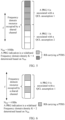
- a quantity N RB of scheduled frequency domain resources (that is, a quantity of scheduled RBs) is equal to 8
- the PRG indication is a wideband
- the first four RBs are one PRG, which is denoted as a PRG 0
- the last four RBs are one PRG, which is denoted as a PRG 1.
- the TCI field indicates two QCL assumptions, which are the QCL assumption 1 and the QCL assumption 2 respectively
- a frequency domain resource corresponding to the PRG 0 is associated with the QCL assumption 1
- a frequency domain resource corresponding to the PRG 1 is associated with the QCL assumption 2.
- the PRG 0 is associated with the QCL assumption 1
- the PRG 1 is associated with the QCL assumption 2.
- a frequency domain resource indicated by a gray-filled box is associated with the QCL assumption 1
- a frequency domain resource indicated by a white-filled box is associated with the QCL assumption 2.
- the first refers to an RB with the earlier index number in the scheduled frequency domain resources, and correspondingly, the last refers to an RB with the later index number in the scheduled frequency domain resources.
- the first frequency domain resource and the second frequency domain resource are used to carry a PDSCH or a physical uplink shared channel (Physical Uplink Shared Channel, PUSCH).
- a PDSCH Physical Uplink Shared Channel
- PUSCH Physical Uplink Shared Channel
- the QCL assumption includes only a type D.
- a frequency domain resource occupied by a target reference signal in scheduled frequency domain resources (which may also be referred to as a scheduled bandwidth) or a frequency domain resource that carries the target reference signal may be determined based on a frequency domain density K and a reference frequency domain resource block.
- the frequency domain density K of a PTRS is determined based on a quantity N RB of scheduled RBs.
- the frequency domain density of the PTRS varies with a value of N RB .
- N RB0 , N RB1 , and N RB2 are preset values (which are values that are configured by a network device side to UE by using RRC signaling based on a value reported by the UE).
- the frequency domain density is 2, indicating that one RB in every two RBs may be used to carry the PTRS, or a frequency domain resource determined at an interval of two RBs is used to carry the PTRS.
- the frequency domain density is 4, indicating that one RB in every four RBs may be used to carry the PTRS, or a frequency domain resource determined at an interval of four RBs is used to carry the PTRS.
- One RB in every K RBs may be used to carry the PTRS, and a specific RB in the K RBs that is used to carry the PTRS may be determined based on a reference RB.
- a ranking of the reference RB in the K RB s with the smallest index number in the scheduled bandwidth is denoted as k ref RB .
- the frequency domain resource corresponding to each QCL assumption should be associated with a target reference signal port (for example, a PTRS port), which may be understood as that target reference signal ports on frequency domain resources associated with different QCL assumptions are different target reference signal ports, or may be understood as that target reference signal ports on frequency domain resources associated with different QCL assumptions are a same reference signal port, but a QCL assumption corresponding to the target reference signal port on the frequency domain resources associated with different QCL assumptions is determined based on a QCL assumption associated with a frequency domain resource in which the target reference signal is located.
- a target reference signal port for example, a PTRS port
- a higher scheduled bandwidth indicates a larger frequency domain density K. It can be learned from the foregoing formula (1) that distribution of PTRSs in the scheduled bandwidth is sparser. It is found that if the frequency domain density K is determined based on N RB described above, the distribution of the PTRSs on the frequency domain resource associated with each QCL assumption is very sparse, affecting estimation performance.
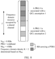
- an association relationship between an RB and a QCL assumption shown in FIG. 5 is the same as that in FIG. 4 .
- the frequency domain density K determined based on N RB equal to 8 is equal to 4
- the reference RB is the 1 st RB in the four RBs
- the four RBs associated with each QCL assumption carry only one PTRS, that is, one subcarrier in only one RB carries the PTRS, and may be used for phase estimation.
- each RB carries one PTRS, which is equivalent to a fact that the four RBs all carry the PTRSs. It can be learned, by comparing FIG. 5 and FIG. 6 , that in the multipoint coordination transmission scenario, if a current reference signal transmission method is still used, PTRSs carried on frequency domain resources associated with the QCL assumption are very sparse, affecting phase estimation performance.
- this disclosure provides a reference signal transmission method.
- a value close to a quantity of frequency domain resources corresponding to each QCL assumption may be used to determine a frequency domain density K, so that a large quantity of PTRSs are carried on the frequency domain resources corresponding to each QCL assumption, to improve phase estimation performance.
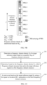
- the reference signal transmission method may include the following steps.
- a receive end determines a frequency domain density K of a target reference signal based on a quantity M RB of frequency domain resources.
- the quantity M RB of frequency domain resources is greater than zero and less than N RB
- N RB is a quantity of scheduled frequency domain resources. It can be learned that M RB used when the frequency domain density K is determined in this implementation is less than N RB . Therefore, the determined frequency domain density K is small. It can be learned by using a formula (1) that RBs carrying PTRSs are close, to help improve a density of carrying the PTRS. Further, when a quantity of scheduled RBs is small, a redundant PTRS can be avoided based on the reference signal transmission method in this disclosure.
- M RB is equal to dividing N RB by N QCL and performing a ceiling operation, or is equal to dividing N RB by N QCL and performing a floor operation
- N QCL is a total quantity of QCL assumptions associated with the scheduled frequency domain resources.
- the total quantity is a quantity of TCI states or QCL assumptions indicated by a TCI field in DCI.
- N QCL is 2.
- N QCL is a quantity of TCI states indicated by a TCI field in DCI.
- N QCL is a quantity of TCI states indicated by a TCI field configured by using RRC signaling.
- M RB is equal to dividing N RB by N QCL .
- the quantity of frequency domain resources in this specification is a quantity of frequency domain resource blocks included in the frequency domain resources.
- the frequency domain resource block is an RB, that is, the quantity of frequency domain resources is a quantity of RBs included in the frequency domain resources.
- M RB is equal to a quantity of first frequency domain resources, or is equal to a quantity of second frequency domain resources.
- M RB is equal to a quantity of RBs of a frequency domain resource associated with one QCL assumption in all RBs occupied by a scheduled PDSCH.
- the receive end determines, based on the frequency domain density K, a third frequency domain resource that carries the target reference signal in the first frequency domain resource and a fourth frequency domain resource that carries the target reference signal in the second frequency domain resource.
- the scheduled frequency domain resources include the first frequency domain resource and the second frequency domain resource.
- the first frequency domain resource is associated with a first quasi co-location QCL assumption
- the second frequency domain resource is associated with a second QCL assumption.
- a third frequency domain resource that carries the target reference signal in the first frequency domain in step 102 includes: mapping the PTRS once starting from a reference frequency domain resource block in the scheduled frequency domain resources at an interval of K frequency domain resource blocks, to obtain one or more frequency domain resource blocks; and using a frequency domain resource block belonging to the first frequency domain resource in the one or more frequency domain resource blocks as the third frequency domain resource that carries the target reference signal.
- a fourth frequency domain resource that carries the target reference signal in the second frequency domain resource includes: mapping the PTRS once starting from the reference frequency domain resource block in the scheduled frequency domain resources at an interval of K frequency domain resource blocks, to obtain one or more frequency domain resource blocks; and using a frequency domain resource block belonging to the second frequency domain resource in the one or more frequency domain resource blocks as the fourth frequency domain resource that carries the target reference signal.
- a frequency domain resource used to carry the target reference signal includes: mapping the PTRS once starting from the reference frequency domain resource block in the scheduled frequency domain resources at an interval of K frequency domain resource blocks, to obtain one or more frequency domain resource blocks. If the frequency domain resource used to carry the target reference signal belongs to the first frequency domain resource, the frequency domain resource is the third frequency domain resource. In addition, for a received QCL assumption of the carried target reference signal, refer to the first QCL assumption associated with the first frequency domain resource. If the frequency domain resource used to carry the target reference signal belongs to the second frequency domain resource, the frequency domain resource is the fourth frequency domain resource. In addition, for a received QCL assumption of the carried target reference signal, refer to the second QCL assumption associated with the second frequency domain resource.
- FIG. 8 shows the same association relationship between a PRG group and a QCL assumption and the same scheduled frequency domain resources as those in FIG. 5 .
- M RB is equal to dividing N RB by N QCL and performing a ceiling operation, that is, M RB is equal to 4. Because 4 is less than 8, similar to FIG. 5 , if the frequency domain density is determined by using a preset value shown in Table 2, the frequency domain density determined by using 4 may be less than the frequency domain density 4 determined by using 8. Therefore, it is assumed that the frequency domain density K determined based on M RB that is equal to 4 is equal to 2.
- a reference RB in the 8 RBs is the 1 st RB in aPRG 0
- the PTRS is mapped once at an interval of 2 RBs, and one or more obtained RBs are respectively the 1 st RB and the 3 rd RB in the PRG 0, and the 1 st RB and the 3 rd RB in a PRG 1.
- two RBs carry PTRSs on a frequency domain resource associated with each QCL assumption.
- a quantity of PTRSs carried on the frequency domain resource associated with each QCL assumption is increased, to help improve phase estimation performance.
- the third frequency domain resource and the fourth frequency domain resource may be determined according to the foregoing formula (1).
- n RNTI is a sequence value used for the DCI.
- a reference position of k is a start subcarrier position in the frequency domain resource block.
- N SC RB indicates a total quantity of subcarriers in one frequency domain resource block.
- that the receive end determines, based on the frequency domain density K, a third frequency domain resource that carries the target reference signal in the first frequency domain in step 102 includes: mapping the PTRS once starting from a reference frequency domain resource block in the first frequency domain resource at an interval of K frequency domain resource blocks, to obtain one or more frequency domain resource blocks as the third frequency domain resource that carries the target reference signal.
- That the receive end determines, based on the frequency domain density K, a fourth frequency domain resource that carries the target reference signal in the second frequency domain resource includes: mapping the PTRS once starting from a reference frequency domain resource block in the second frequency domain resource at an interval of K frequency domain resource blocks, to obtain one or more frequency domain resource blocks as the fourth frequency domain resource that carries the target reference signal.
- a reference frequency domain resource block in the PRG 0 is the 1 st RB.
- the PTRS is mapped once starting from the 1 st RB at an interval of two RBs, and one or more obtained RBs are respectively the 1 st RB and the 3 rd RB in the PRG 0.
- an RB carrying the PTRS may also be determined in this implementation.
- the frequency domain resource that carries the PTRS may alternatively be determined by using the foregoing formulas (1) to (3).
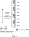
- N RB is equal to 16
- M RB is equal to 8
- K determined based on M RB is 4
- the PRG indication is 2, and two RBs are a PRG group
- a PRG group with an even index number is associated with the QCL assumption 1
- a PRG group with an odd index number is associated with the QCL assumption 2.
- an association relationship between each PRG group and each QCL assumption is that shown in FIG. 9A .
- APRG indicated by using a gray-filled box is associated with the QCL assumption 1
- a PTRS indicated by using a white-filled box is associated with the QCL assumption 2.
- the PTRS is mapped once starting from the reference RB at an interval of four RBs, and obtained RBs carrying the PTRSs are respectively RBs or PRGs indicated by using gray grid-filled boxes shown in FIG. 9A .
- both a transmit end and the receive end may determine, by using the mapping manner described in the foregoing implementation, the RB that carries the PTRS.
- FIG. 9B an assumption case in FIG. 9B is the same as that in FIG. 9A .
- FIG. 9B an RB carrying the PTRS is first determined for a frequency domain resource associated with the QCL assumption 1, and then an RB carrying the PTRS is determined for a frequency domain resource associated with the QCL assumption 2.
- the PTRS distribution shown in FIG. 9B may be obtained, so that a frequency domain resource associated with each QCL assumption carries the PTRS.
- the receive end receives the target reference signal by using the first quasi co-location QCL assumption on the third frequency domain resource, and receives the target reference signal by using the second quasi co-location QCL assumption on the fourth frequency domain resource.
- the target reference signal carried on the third frequency domain resource is associated with a DMRS carried on the first frequency domain resource.
- a target reference signal port for example, a PTRS port
- a DMRS port corresponding to a DMRS carried on the first frequency domain resource.
- the receive end may obtain the first QCL assumption through measurement on the DMRS carried on the third frequency domain resource, for example, a QCL assumption type A, type B, or type D to receive the PTRS.
- the receive end may further perform phase or phase estimation by using the PTRS carried on the third frequency domain resource, and receive, by using a phase estimation result and the first QCL assumption, data and the DMRS that are carried on the first frequency domain resource.
- the receive end may further assist DMRS estimation by using a phase estimation result obtained by using the PTRS.
- the target reference signal carried on the third frequency domain resource corresponds to a target reference signal port (for example, a PTRS port) 0
- the DMRS carried on the first frequency domain resource corresponds to a DMRS port 0
- the target reference signal port (for example, the PTRS port) 0 is associated with the DMRS port 0, indicating that QCL types A and QCL types D used by the target reference signal port (for example, the PTRS port) 0 and the DMRS port 0 are the same
- an estimation result of the PTRS corresponding to the target reference signal port (for example, the PTRS port) 0 may be used to adjust QCL types B used by the DMRS port 0.
- the target reference signal carried on the fourth frequency domain resource is associated with a DMRS carried on the second frequency domain resource.
- a target reference signal port for example, a PTRS port
- a DMRS port corresponding to a DMRS carried on the second frequency domain resource.
- the receive end may obtain the second QCL assumption through measurement on the DMRS carried on the fourth frequency domain resource, for example, a QCL assumption type A, type B, or type D to receive the PTRS.
- the receive end may further perform phase or phase estimation by using the PTRS carried on the fourth frequency domain resource, and receive, by using a phase estimation result and the second QCL assumption, data and the DMRS that are carried on the second frequency domain resource.
- the receive end may further assist DMRS estimation by using a phase estimation result obtained by using the PTRS.
- the target reference signal carried on the fourth frequency domain resource corresponds to a target reference signal port (for example, a PTRS port) 1
- the DMRS carried on the first frequency domain resource corresponds to a DMRS port 1
- the target reference signal port (for example, the PTRS port) 1 is associated with the DMRS port 1, indicating that QCL types A and QCL types D used by the target reference signal port (for example, the PTRS port) 1 and the DMRS port 1 are the same
- an estimation result of a channel parameter (for example, a phase) of the target reference signal corresponding to the target reference signal port (for example, the PTRS port) 1 may be used to adjust a channel parameter used by the DMRS port 1.
- the frequency domain density K is determined by using a frequency domain resource less than N RB , so that phase estimation performance can be improved.
- a frequency domain density K1 of the first frequency domain resource and a frequency domain density K2 of the second frequency domain resource may also be respectively determined.
- the first N RB / 2 RBs are used to determine the frequency domain density K1 of the PTRS corresponding to the PTRS port 0, and the remaining N RB / 2 RBs are used to determine the frequency domain density K2 of the PTRS corresponding to the PTRS port 1. Because quantities of frequency domain resources associated with various QCL assumptions are not necessarily strictly equal, frequency domain densities of two PTRS ports may be different.
- the PTRS corresponding to the PTRS port 0 is mapped only to the first N RB / 2 RBs (where the first N RB / 2 RBs are associated with the QCL assumption 1), and the PTRS corresponding to the PTRS port 1 is mapped only to the remaining N RB / 2 RBs (where the remaining N RB / 2 RBs are associated with the QCL assumption 2).
- the PTRS corresponding to the PTRS port 0 is mapped once on the first N RB / 2 RBs at an interval of K1 RBs, and the PTRS corresponding to the PTRS port 1 is mapped once on remaining N RB / 2 RBs at an interval of K2 RBs.
- a quantity of RBs of all PRGs with even index numbers is used to determine the frequency domain density K1 of the PTRS corresponding to the PTRS port 0 and a quantity of RBs of all PRGs with odd index numbers is used to determine the frequency domain density K2 of the PTRS corresponding to the PTRS port 1.
- the PTRS corresponding to the PTRS port 0 is mapped only to all the PRGs with the even index numbers (where all the PRGs with the even index numbers are associated with the QCL assumption 1).
- the PTRS corresponding to the PTRS port 1 is mapped only to all the PRGs with the odd index numbers (where all the PRGs with the odd index numbers are associated with the QCL assumption 2).
- the PTRS corresponding to the PTRS port 0 is mapped once on even PRGs at an interval of K1 RBs, and the PTRS corresponding to the PTRS port 1 is mapped once on odd PRGs at an interval of K2 RBs.
- different QCL assumptions may be used to receive corresponding data and DMRSs on different frequency domain resources.
- the PTRS in addition to the case in which the PTRS is also received by using different QCL assumptions described in the transmission method 1 (where the PTRS may be received by a single port, but QCL assumptions on different frequency domain resources are different; or the PTRS may be received by a plurality of ports, and QCL assumptions of different ports are different), the PTRS may alternatively be limited to being received by using only one QCL assumption.
- problems such as a processing capability of UE and resource overheads occupied by RSs are mainly considered.
- this disclosure further provides a reference signal transmission method.
- the reference signal transmission method may be used in a case in which a target reference signal port uses only one QCL assumption for receiving.
- the target reference signal port (for example, a PTRS port) may be associated with one of a plurality of QCL assumptions indicated by DCI. That is, the QCL assumption may be used to receive the target reference signal port.
- the foregoing association relationship may be predefined, that is, when a plurality of QCL assumptions are indicated in DCI or RRC signaling, the 1 st QCL assumption is used as the QCL assumption of the PTRS by default, or the 2 nd QCL assumption is used as the QCL assumption of the PTRS by default.
- the target reference signal port (for example, the PTRS port) may be carried on a frequency domain resource corresponding to the QCL assumption associated with the target reference signal port.
- the PTRS port is associated with a first QCL assumption.
- a receive end only needs to determine a third frequency domain resource that carries the PTRS in a first frequency domain resource.
- the receive end only needs to receive, by using the first QCL assumption, the PTRS carried on the third frequency domain resource.
- the PTRS port is associated with a second QCL assumption is used.
- a receive end only needs to determine a fourth frequency domain resource that carries the PTRS in a second frequency domain resource.
- the receive end only needs to receive, by using the second QCL assumption, the PTRS carried on the fourth frequency domain resource.
- the first case is used as an example for description.
- the PTRS port may be associated with a DMRS port corresponding to a QCL assumption.
- QCL assumptions of the PTRS port and the associated DMRS port are the same.
- the QCL assumption includes one or more of QCL assumptions type A, type B, and type D.
- QCL assumptions of the PTRS port and an unassociated DMRS port are different, that is, a QCL assumption of the unassociated DMRS port is different from a QCL assumption of the PTRS port.
- the QCL assumptions type B of the PTRS port and the unassociated DMRS port are the same.
- DMRS ports using a plurality of QCL assumptions share the PTRS port, or DMRSs in all scheduling bandwidths share the PTRS.
- the target reference signal transmission method may include the following steps.
- a receive end determines a frequency domain density K of a target reference signal based on a quantity M RB of frequency domain resources.
- M RB may be equal to a quantity of frequency domain resources associated with a QCL assumption, is equal to N RB divided by N QCL and performing a ceiling operation, or is equal to N RB divided by N QCL and performing a floor operation.
- N RB is a quantity of scheduled frequency domain resources.
- N QCL is a total quantity of QCL assumptions associated with the scheduled frequency domain resources.
- the receive end determines, based on the frequency domain density K, a third frequency domain resource that carries the target reference signal in a first frequency domain resource.
- that the receive end determines, based on the frequency domain density K, a third frequency domain resource that carries the target reference signal in a first frequency domain includes: mapping a PTRS once starting from a reference frequency domain resource block in the first frequency domain resource at an interval of K frequency domain resource blocks, to obtain one or more frequency domain resource blocks as the third frequency domain resource that carries the target reference signal.
- the frequency domain resource that carries the PTRS may alternatively be determined by using the foregoing formulas (1) to (3). It should be noted that, in this case, a maximum value of i in the formulas (1) and formula (2) is determined based on a quantity of first frequency domain resources.
- the receive end receives the target reference signal by using a first quasi co-location QCL assumption on the third frequency domain resource.
- the scheduled frequency domain resources include the first frequency domain resource and a second frequency domain resource.
- the first frequency domain resource is associated with the first quasi co-location QCL assumption
- the second frequency domain resource is associated with a second QCL assumption.
- steps 201 to 203 in this example are respectively parts in steps 101 to 103. Therefore, for related descriptions of steps 201 to 203, refer to related content in the foregoing second part. Details are not described herein again.
- a PTRS port determines, starting from a reference RB in the first N RB / 2 RBs by using a QCL assumption associated with the first N RB / 2 RBs in a manner of mapping the PTRS once at an interval of K RBs, the frequency domain resource that carries the PTRS.
- the PTRS port is associated with a DMRS port on the first N RB / 2 RBs.
- QCL assumptions type A and/or type D of the PTRS port and the DMRS port are the same, but the PTRS is not associated with a DMRS port located on remaining RBs. That is, a QCL type B of the PTRS is only the same as a QCL type B of the DMRS port.
- a PRG indication is 2 or 4. Assuming that the PTRS port is associated with a QCL assumption corresponding to a PRG with an even index number, the frequency domain resource that carries the PTRS is determined starting from a reference RB in all PRGs with even index numbers in a manner of mapping the PTRS once at an interval of K RBs.
- mapping is performed once at an interval of K RBs.
- the PTRS port is associated with a DMRS port located on an even PRG, that is, QCL assumptions type A and/or type D of the PTRS port and the DMRS port are the same, but the PTRS is not associated with a DMRS port located on an odd PRG. That is, a QCL type B of the PTRS is only the same as a QCL type B of the DMRS port.
- the frequency domain densities in FIG. 11 and FIG. 8 are the same. It is assumed that a PTRS port 0 is configured and the PTRS port 0 is associated with a QCL assumption 1. Assuming that a reference RB in all PRGs with even index numbers associated with the QCL assumption 1 is the 1 st RB, based on the reference signal transmission method described in FIG. 10 , it may be determined that an RB carrying the PTRS is an RB indicated by a gray grid-filled box in FIG. 11 . Correspondingly, the receive end may receive the PTRS on these RBs by using the QCL assumption 1. It can be learned that a frequency domain resource associated with a QCL assumption 2 does not carry the PTRS. It can be learned that the target reference signal transmission method can specify a transmission rule of the PTRS, to avoid a problem that transmission performance is affected due to an unclear rule.
- this disclosure further provides a target reference signal (for example, a PTRS) transmission method.
- the target reference signal for example, the PTRS
- the target reference signal (for example, the PTRS) transmission method is different from the implementation in the manner 1.
- a manner of mapping the target reference signal is determined based on all scheduling bandwidths, that is, both a frequency domain density and a mapping manner are determined based on all the scheduling bandwidths.
- a PTRS port may be associated with a DMRS port corresponding to a QCL assumption.
- QCL assumptions of the PTRS port and the associated DMRS port are the same.
- the QCL assumption includes one or more of QCL assumptions type A, type B, and type D.
- QCL assumptions of the PTRS port and an unassociated DMRS port are different, that is, a QCL assumption of the unassociated DMRS port is different from a QCL assumption of the PTRS port.
- the QCL assumptions type B of the PTRS port and the unassociated DMRS port are the same.
- DMRS ports using a plurality of QCL assumptions share the PTRS port, or DMRSs in all scheduling bandwidths share the PTRS.
- the receive end may receive, based on a first QCL assumption or a second QCL assumption, the target reference signals (for example, the PTRSs) carried on a third frequency domain resource and a fourth frequency domain resource.
- the target reference signals for example, the PTRSs
- the receive end may use a channel parameter (for example, a frequency offset) estimation result of the target reference signal (for example, the PTRS) to adjust a channel parameter (for example, a QCL type-B) in the first QCL assumption and/or the second QCL assumption.
- a channel parameter for example, a frequency offset
- the target reference signal for example, the PTRS
- a channel parameter for example, a QCL type-B
- signaling may be used to indicate, to the receive end, a specific manner of receiving the target reference signal (for example, the PTRS).
- a specific manner of receiving the target reference signal for example, the PTRS.
- the PTRS is sent in the PTRS mapping manner corresponding to the manner 2; otherwise, the PTRS is sent in the PTRS mapping manner corresponding to the manner 1.
- the PTRS when a quantity of configured PTRS ports is 1, the PTRS is sent in the PTRS mapping manner corresponding to the manner 1; when a quantity of configured PTRS ports is 2, the PTRS is sent in the PTRS mapping manner corresponding to the manner 2.
- one target reference signal port for example, the PTRS port
- channel parameter for example, a frequency offset
- a same target reference signal port for example, the PTRS port
- one target reference signal port for example, the PTRS port
- the target reference signal for example, the PTRS
- different QCL assumptions may be used on a same time-frequency domain resource to receive corresponding data and DMRSs, and data and a DMRS that correspond to each QCL assumption correspond to one different port, or each QCL assumption corresponds to a CDM group of DMRSs.
- a DMRS port 0 or DMRS ports 0 and 1 corresponds/correspond to a QCL assumption 1
- a DMRS port 2 or DMRS ports 2 and 3 corresponds/correspond to a QCL assumption 2.
- the PTRS on the time-frequency domain resource is limited to be received by using one QCL assumption, that is, one port is configured for the PTRS.
- problems such as a processing capability of UE and resource overheads occupied by RSs are considered.
- problems such as a processing capability of UE and resource overheads occupied by RSs are considered.
- a QCL assumption used for the PTRS and an association relationship between the PTRS and a DMRS also become an urgent problem to be resolved.
- the target reference signal port (for example, a PTRS port) may be associated with one of a plurality of QCL assumptions indicated by DCI. That is, the QCL assumption may be used to receive the target reference signal port.
- the foregoing association relationship may be predefined, that is, when a plurality of QCL assumptions are indicated in DCI or RRC signaling, the 1 st QCL assumption is used as the QCL assumption of the PTRS by default, or the 2 nd QCL assumption is used as the QCL assumption of the PTRS by default.
- a PTRS port may be associated with a DMRS port corresponding to a QCL assumption.
- QCL assumptions of the PTRS port and the associated DMRS port are the same.
- the QCL assumption includes one or more of QCL assumptions type A, type B, and type D.
- QCL assumptions of the PTRS port and an unassociated DMRS port are different, that is, a QCL assumption of the unassociated DMRS port is different from a QCL assumption of the PTRS port.
- the QCL assumptions type B of the PTRS port and the unassociated DMRS port are the same.
- DMRS ports using a plurality of QCL assumptions share the PTRS port.
- the reference signal transmission method may include the following steps.
- a receive end receives TCI indication signaling, where the TCI indication signaling indicates a plurality of QCL assumptions (TCI states).
- the plurality of QCL assumptions each correspond to one CDM group of DMRSs.
- a CDM group 1 of DMRSs uses a QCL assumption 1 for receiving
- a CDM group 2 of DMRSs uses a QCL assumption 2 for receiving.
- the receive end determines, according to a predefined rule, a QCL assumption used for a PTRS.
- the 1 st QCL assumption or the last QCL assumption in the plurality of QCL assumptions may be used for the PTRS.
- the PTRS is associated with a DMRS port in a default CDM group.
- the PTRS is associated with a DMRS port in the 1 st CDM group that is indicated, or the PTRS is associated with a DMRS port in the last CDM that is indicated.
- the PTRS port and the associated DMRS port have a same QCL assumption type A and/or type D.
- the PTRS port and an unassociated DMRS port have a same QCL assumption type B.
- the receive end receives the PTRS based on the QCL assumption used for the PTRS.
- a PTRS transmission method can be determined, to improve channel estimation performance.
- the time domain resource corresponding to each QCL assumption should be associated with a target reference signal port (for example, a PTRS port), to assist a DMRS carried on the time domain resource in performing channel estimation, and improve channel estimation performance. Therefore, for the foregoing multipoint coordination transmission scenario, two target reference signal ports (for example, PTRS ports) may be configured, and one target reference signal port (for example, a PTRS port) is associated with a QCL assumption used for data and a DMRS that are transmitted by one transmission node.
- a target reference signal port for example, a PTRS port
- 0 is associated with a QCL assumption 1
- a target reference signal port (for example, a PTRS port) 2 is associated with a QCL assumption 2.
- scheduled time domain resources include at least two time domain resources (that is, at least two time periods) in time domain, each time domain resource corresponds to one or more OFDM symbols, any two time domain resources do not overlap in time domain, and each time domain resource may be associated with a different QCL assumption.
- each time domain resource needs to carry a target reference signal (for example, a PTRS). Therefore, this disclosure further provides a reference signal transmission method on a time domain resource.
- the reference signal transmission method includes the following steps.
- a receive end determines a time domain density L of a target reference signal based on modulation and coding scheme MCS information.
- the receive end maps the target reference signal once starting from a reference time domain resource block in a first time domain resource at an interval of L time domain resource blocks, to obtain a third time domain resource that carries the target reference signal; and maps the target reference signal once starting from a reference time domain resource block in a second time domain resource at an interval of L time domain resource blocks, to obtain a fourth time domain resource that carries the target reference signal.
- the receive end receives, by using a first QCL assumption, the target reference signal carried on the third time domain resource, and receives, by using a second QCL assumption, the target reference signal carried on the fourth time domain resource.
- the MCS information is used to indicate information such as a modulation and coding scheme of scheduled time domain resources.
- the scheduled time domain resources include the first time domain resource and the second time domain resource.
- the first time domain resource is associated with the first QCL assumption
- the second time domain resource is associated with the second QCL assumption.
- a target reference signal port corresponding to the target reference signal carried on the third time domain resource is associated with a DMRS port corresponding to a DMRS carried on the first time domain resource.
- a target reference signal port corresponding to the target reference signal carried on the fourth time domain resource is associated with a DMRS port corresponding to a DMRS carried on the second time domain resource.
- the modulation and coding scheme information may be one of a modulation and coding scheme index I MCS , a modulation order Qm, a target code rate Rx, spectral efficiency, and the like.
- the modulation and coding scheme information is a modulation and coding scheme index I MCS .
- That a receive end determines a time domain density L of a target reference signal based on modulation and coding scheme MCS information in step 301 may be: determining, by using a preset value shown in Table 3 (for example, ptrs-MCS 1 , ptrs-MCS 2 , ptrs-MCS 3 , or ptrs-MCS 4 ), an interval in which I MCS is located, and further determining the time domain density L.
- Table 3 for example, ptrs-MCS 1 , ptrs-MCS 2 , ptrs-MCS 3 , or ptrs-MCS 4
- the first time domain resource is the 1 st symbol to the 5 th symbol in a slot, that is, the symbols indicated by using gray-filled boxes.
- the second time domain resource is the 6 th symbol to the 10 th symbol in the slot, that is, the symbols indicated by using white-filled boxes.
- the first time domain resource is associated with a QCL assumption 1
- the second time domain resource is associated with a QCL assumption 2.
- the reference time domain resource block in the first time domain resource may be the 2 nd symbol in the slot
- the reference time domain resource block in the second time domain resource may be the 7 th symbol in the slot.
- a PTRS is mapped once starting from the 2 nd symbol at an interval of L(2) symbols in the first time domain resource, and determined symbols that carry the PTRS are respectively the 2 nd symbol and the 4 th symbol in the slot; a PTRS is mapped once starting from the 7 th symbol at an interval of L(2) symbols in the second time domain resource, and determined symbols that carry the PTRS are respectively the 7 th symbol and the 9 th symbol in the slot.
- the symbols that carry the PTRS are symbols indicated by using gray grid-filled boxes in FIG. 13 .
- the receive end may receive, by using a channel parameter (for example, a frequency offset) estimation result of the target reference signal (for example, the PTRS) and the first QCL assumption, data and the DMRS that are carried on the first time domain resource.
- the receive end may receive, by using a channel parameter (for example, a frequency offset) estimation result of the target reference signal (for example, the PTRS) and the second QCL assumption, data and the DMRS that are carried on the second time domain resource.
- the target reference signal for example, the PTRS
- channel parameter for example, the frequency offset
- this disclosure further provides a reference signal transmission method.
- a receive end may perform step 301, perform some operations in step 302, and perform some operations in step 303.
- step 402 Some operations in step 402 are as follows.
- the receive end maps a PTRS once starting from a reference time domain resource block at an interval of L time domain resource blocks in a first time domain resource, to obtain a third time domain resource that carries the PTRS; or maps a PTRS once starting from a reference time domain resource block at an interval of L time domain resource blocks in a second time domain resource, to obtain a fourth time domain resource that carries the PTRS.
- step 403 Some operations in step 403 are as follows.
- the receive end receives, by using a first QCL assumption, the target reference signal carried on the third time domain resource; or receives, by using a second QCL assumption, the target reference signal carried on the fourth time domain resource.
- the first time domain resource is the same as the second time domain resource
- the third time domain resource is the same as the fourth time domain resource.
- one configured target reference signal port (for example, a PTRS port) is associated with one QCL assumption, and correspondingly, the PTRS may be mapped or carried on a time domain resource associated with the QCL assumption. Further, the receive end or a transmit end receives the target reference signal (for example, the PTRS) on the time domain resource by using the QCL assumption. A time domain resource associated with another QCL assumption does not carry the target reference signal (for example, the PTRS).
- a plurality of QCL assumptions indicated by DCI may be associated with a same target reference signal port (for example, a PTRS port).
- a target reference signal port for example, a PTRS port.
- the time domain resource that carries the target reference signal is time domain resource blocks that carry the target reference signal (for example, the PTRS) that are obtained by mapping the target reference signal (for example, the PTRS) once starting from a reference time domain resource block in the scheduled time domain resources at an interval of L time domain resource blocks until the last time domain resource block in the scheduled time domain resources.
- a reference time domain resource block in a scheduled slot is the 2 nd symbol.
- the PTRS is mapped once starting from the 2 nd symbol at an interval of two symbols until the PTRS is mapped once to the 9 th symbol, to obtain all symbols that carry the PTRS.
- the mapping manner in which mapping is performed starting from respective reference time domain resource blocks in the first time domain resource and the second time domain resource described in FIG. 12 does not need to be used.
- the receive end may receive, by using QCL types A and D of one of the QCL assumptions, the target reference signal (for example, the PTRS) carried on the scheduled time domain resources, and adjust a channel parameter (for example, QCL types B) in one or all of the QCL assumptions by using a channel parameter (frequency offset) estimation result of the target reference signal (for example, the PTRS).
- the target reference signal for example, the PTRS
- a channel parameter for example, QCL types B
- the 1 st target reference signal (for example, the PTRS) transmission method in this part supports two target reference signal ports (for example, PTRS ports), to ensure that each QCL assumption has the target reference signal (for example, the PTRS) with frequency offset estimation, that is, the target reference signal is carried.
- two target reference signal ports for example, PTRS ports
- the 2 nd target reference signal (for example, the PTRS) transmission method in this part may support a case in which one target reference signal port (for example, a PTRS port) is configured, to ensure that channel parameter (for example, the frequency offset) estimation of a QCL assumption is accurate and low signaling overheads are kept; or to ensure that each QCL assumption has channel parameter (for example, the frequency offset) estimation and shares a same target reference signal port (for example, the PTRS port), thereby reducing signaling overheads and complexity of the channel parameter (for example, the frequency offset) estimation.
- the reference signal transmission method in frequency domain may be used in combination with the reference signal transmission method in time domain, that is, the reference signal transmission method in frequency domain may be used in combination with the reference signal transmission method in time domain.
- the target reference signal is transmitted on the scheduled time-frequency resources, to improve channel estimation performance.
- FIG. 15 is a schematic diagram of a structure of a communication apparatus according to an example of this disclosure.
- the communication apparatus 1500 shown in FIG. 15 may include a transceiver unit 1501 and a processing unit 1502.
- the transceiver unit 1501 may include a sending unit and a receiving unit.
- the sending unit is configured to implement a sending function
- the receiving unit is configured to implement a receiving function
- the transceiver unit 1501 may implement a sending function and/or a receiving function.
- the transceiver unit may alternatively be described as a communication unit.
- the communication apparatus 1500 may be a terminal device, an apparatus in the terminal device, or an apparatus that can be used together with the terminal device.
- the communication apparatus includes a transceiver unit 1501 and a processing unit 1502.
- the processing unit 1502 is configured to: determine a frequency domain density K of a target reference signal based on a quantity M RB of frequency domain resources; determine, based on the frequency domain density K, a third frequency domain resource that carries the target reference signal in a first frequency domain resource and/or a fourth frequency domain resource that carries the target reference signal in a second frequency domain resource.
- the transceiver unit 1501 is configured to: send, by using a first quasi co-location QCL assumption, the target reference signal carried on the third frequency domain resource, and/or send, by using a second quasi co-location QCL assumption, the target reference signal carried on the fourth frequency domain resource.
- the quantity M RB of frequency domain resources is greater than zero and less than N RB , N RB is a quantity of scheduled frequency domain resources, and the scheduled frequency domain resources include the first frequency domain resource and the second frequency domain resource.
- the first frequency domain resource is associated with the first quasi co-location QCL assumption
- the second frequency domain resource is associated with the second QCL assumption
- the communication apparatus includes a transceiver unit 1501 and a processing unit 1502.
- the processing unit 1502 is configured to: determine a time domain density L of a target reference signal based on modulation and coding scheme MCS information; map the target reference signal once starting from a reference time domain resource block in a first time domain resource at an interval of L time domain resource blocks, to obtain a third time domain resource that carries the target reference signal; and/or map the target reference signal once starting from a reference time domain resource block in a second time domain resource at an interval of L time domain resource blocks, to obtain a fourth time domain resource that carries the target reference signal.
- the transceiver unit 1501 is configured to: receive, by using a first QCL assumption, the target reference signal carried on the third time domain resource, and/or receive, by using a second QCL assumption, the target reference signal carried on the fourth time domain resource.
- the MCS information is used to indicate a modulation and coding scheme of scheduled time domain resources.
- the scheduled time domain resources include the first time domain resource and the second time domain resource.
- the first time domain resource is associated with the first QCL assumption
- the second time domain resource is associated with the second QCL assumption.
- the communication apparatus 1300 may be a network device, an apparatus in the network device, or an apparatus that can be used together with the network device.
- the processing unit 1502 is configured to: determine a frequency domain density K of a target reference signal based on a quantity M RB of frequency domain resources; determine, based on the frequency domain density K, a third frequency domain resource that carries the target reference signal in a first frequency domain resource and/or a fourth frequency domain resource that carries the target reference signal in a second frequency domain resource.
- the quantity M RB of frequency domain resources is greater than zero and less than N RB , N RB is a quantity of scheduled frequency domain resources, and the scheduled frequency domain resources include the first frequency domain resource and the second frequency domain resource.
- the first frequency domain resource is associated with a first quasi co-location QCL assumption
- the second frequency domain resource is associated with a second QCL assumption
- the transceiver unit 1501 is configured to: send, by using the first quasi co-location QCL assumption, the target reference signal carried on the third frequency domain resource, and/or send, by using the second quasi co-location QCL assumption, the target reference signal carried on the fourth frequency domain resource.
- the communication apparatus includes a transceiver unit 1501 and a processing unit 1502.
- the processing unit 1502 is configured to: determine a time domain density L of a target reference signal based on modulation and coding scheme MCS information; map the target reference signal once starting from a reference time domain resource block in a first time domain resource at an interval of L time domain resource blocks, to obtain a third time domain resource that carries the target reference signal; and/or map the target reference signal once starting from a reference time domain resource block in a second time domain resource at an interval of L time domain resource blocks, to obtain a fourth time domain resource that carries the target reference signal.
- the transceiver unit 1501 is configured to: send, by using a first QCL assumption, the target reference signal carried on the third time domain resource, and/or receive, by using a second QCL assumption, the target reference signal carried on the fourth time domain resource.
- the MCS information is used to indicate a modulation and coding scheme of scheduled time domain resources.
- the scheduled time domain resources include the first time domain resource and the second time domain resource.
- the first time domain resource is associated with the first QCL assumption
- the second time domain resource is associated with the second QCL assumption.
- FIG. 16 is a schematic diagram of a structure of a communication apparatus.
- the communication apparatus 1600 may be a network device, may be a terminal device, may be a chip, a chip system, a processor, or the like that supports a network device in implementing the foregoing methods, or may be a chip, a chip system, a processor, or the like that supports a terminal device in implementing the foregoing methods.
- the apparatus may be configured to implement the methods described in the foregoing method examples. For details, refer to the descriptions in the foregoing method examples.
- the communication apparatus 1600 may include one or more processors 1601.
- the processor 1601 may be a general-purpose processor, a dedicated processor, or the like.
- the processor 1601 may be a baseband processor or a central processing unit.
- the baseband processor may be configured to process a communication protocol and communication data.
- the central processing unit may be configured to: control a communication apparatus (for example, a base station, a baseband chip, a terminal, a terminal chip, a DU, or a CU), execute a software program, and process data of the software program.
- the communication apparatus 1600 may include one or more memories 1602.
- the memory 1602 stores instructions 1604, and the instructions may be run on the processor 1601, to enable the apparatus 1600 to perform the methods described in the foregoing method examples.
- the memory 1602 may further store data.
- the processor 1601 and the memory 1602 may be separately disposed, or may be integrated together.
- the communication apparatus 1600 may further include a transceiver 1605 and an antenna 1606.
- the transceiver 1605 may be referred to as a transceiver unit, a transceiver machine, a transceiver circuit, or the like, and is configured to implement a transceiver function.
- the transceiver 1605 may include a receiver and a transmitter.
- the receiver may be referred to as a receiving machine, a receiver circuit, or the like, and is configured to implement a receiving function.
- the transmitter may be referred to as a transmitting machine, a transmitter circuit, or the like, and is configured to implement a sending function.
- the communication apparatus 1600 is the terminal device.
- the processor 1601 is configured to perform steps 101 and 102 in FIG. 7 , steps 201 and 202 in FIG. 10 , steps 301 and 302 in FIG. 12 , and steps 401 and 402 in FIG. 13 .
- the transceiver 1605 is configured to perform step 103 in FIG. 7 , step 203 in FIG. 10 , step 303 in FIG. 12 , and step 403 in FIG. 13 .
- the communication apparatus 1600 is the network device.
- the processor 1601 is configured to perform steps 101 and 102 in FIG. 7 , steps 201 and 202 in FIG. 10 , steps 301 and 302 in FIG. 12 , and steps 401 and 402 in FIG. 13 .
- the transceiver 1605 is configured to: perform step 103 in FIG. 7 , where a "receiving" operation needs to be replaced with a "sending” operation; perform step 203 in FIG. 10 , where a "receiving" operation needs to be replaced with a "sending” operation; perform step 303 in FIG. 12 , where a "receiving” operation needs to be replaced with a "sending” operation; and perform step 403 in FIG. 13 , where a "receiving” operation needs to be replaced with a "sending” operation.
- the processor 1601 may include a transceiver configured to implement receiving and sending functions.
- the transceiver may be a transceiver circuit, an interface, or an interface circuit.
- a transceiver circuit, an interface, or an interface circuit configured to implement the sending function and a transceiver circuit, an interface, or an interface circuit configured to implement the receiving function may be separated, or may be integrated together.
- the transceiver circuit, the interface, or the interface circuit may be configured to read and write code or data.
- the transceiver circuit, the interface, or the interface circuit may be configured to transmit or transfer a signal.
- the processor 1601 may store instructions 1603, and the instructions 1603 are run on the processor 1601, so that the communication apparatus 1600 performs the methods described in the foregoing method examples.
- the instructions 1603 may be fixed in the processor 1601, and in this case, the processor 1601 may be implemented by hardware.
- the communication apparatus 1600 may include a circuit, and the circuit may implement the sending function, the receiving function, or the communication function in the foregoing method examples.
- the processor and the transceiver that are described in this disclosure may be implemented on an integrated circuit (integrated circuit, IC), an analog IC, a radio frequency integrated circuit RFIC, a hybrid signal IC, an application-specific integrated circuit (application-specific integrated circuit, ASIC), a printed circuit board (printed circuit board, PCB), an electronic device, or the like.
- the processor and the transceiver may alternatively be manufactured by using various IC technologies, for example, a complementary metal oxide semiconductor (complementary metal oxide semiconductor, CMOS), an N-type metal oxide semiconductor (nMetal oxide semiconductor, NMOS), a P-type metal oxide semiconductor (positive channel metal oxide semiconductor, PMOS), a bipolar junction transistor (Bipolar Junction Transistor, BJTj, a bipolar CMOS (BiCMOS), silicon germanium (SiGe), and gallium arsenide (GaAs).
- CMOS complementary metal oxide semiconductor
- NMOS N-type metal oxide semiconductor
- PMOS positive channel metal oxide semiconductor
- BJTj bipolar junction transistor
- BiCMOS bipolar Junction Transistor
- SiGe silicon germanium
- GaAs gallium arsenide
- the communication apparatus in the foregoing example may be a network device or a terminal device.
- a scope of the communication apparatus described in this disclosure is not limited thereto, and a structure of the communication apparatus may not be limited by FIG. 14 .
- the communication apparatus may be an independent device or a part of a large device.
- the communication apparatus may be:
- the communication apparatus may be a chip or a chip system
- the chip 1700 shown in FIG. 17 includes a processor 1701 and an interface 1702. There may be one or more processors 1701, and there may be a plurality of interfaces 1702.
- the processor 1701 is configured to: determine a frequency domain density K of a target reference signal based on a quantity M RB of frequency domain resources; and determine, based on the frequency domain density K, a third frequency domain resource that carries the target reference signal in a first frequency domain resource, and/or a fourth frequency domain resource that carries the target reference signal in a second frequency domain resource.
- the interface 1702 is configured to: receive, by using a first quasi co-location QCL assumption, the target reference signal carried on the third frequency domain resource, and/or receive, by using a second quasi co-location QCL assumption, the target reference signal carried on the fourth frequency domain resource.
- the processor 1701 is configured to: determine a time domain density L of a target reference signal based on modulation and coding scheme MCS information; map the target reference signal once starting from a reference time domain resource block in a first time domain resource at an interval of L time domain resource blocks, to obtain a third time domain resource that carries the target reference signal; and/or map the target reference signal once starting from a reference time domain resource block in a second time domain resource at an interval of L time domain resource blocks, to obtain a fourth time domain resource that carries the target reference signal.
- the interface 1702 is configured to: receive, by using a first QCL assumption, the target reference signal carried on the third time domain resource, and/or receive, by using a second QCL assumption, the target reference signal carried on the fourth time domain resource.
- the processor 1701 is configured to: determine a frequency domain density K of a target reference signal based on a quantity M RB of frequency domain resources; and determine, based on the frequency domain density K, a third frequency domain resource that carries the target reference signal in a first frequency domain resource, and/or a fourth frequency domain resource that carries the target reference signal in a second frequency domain resource.
- the interface 1702 is configured to: send, by using a first quasi co-location QCL assumption, the target reference signal carried on the third frequency domain resource, and/or send, by using a second quasi co-location QCL assumption, the target reference signal carried on the fourth frequency domain resource.
- the processor 1701 is configured to: determine a time domain density L of a target reference signal based on modulation and coding scheme MCS information; map the target reference signal once starting from a reference time domain resource block in a first time domain resource at an interval of L time domain resource blocks, to obtain a third time domain resource that carries the target reference signal; and/or map the target reference signal once starting from a reference time domain resource block in a second time domain resource at an interval of L time domain resource blocks, to obtain a fourth time domain resource that carries the target reference signal.
- the interface 1702 is configured to: send, by using a first QCL assumption, the target reference signal carried on the third time domain resource, and/or receive, by using a second QCL assumption, the target reference signal carried on the fourth time domain resource.
- the chip further includes a memory 1703.
- the memory 1703 is configured to store program instructions and data that are necessary for the terminal device.
- This disclosure further provides a computer-readable storage medium
- the computer-readable storage medium stores a computer program.
- the computer-readable storage medium is executed by a computer, functions of any one of the foregoing method examples are implemented.
- This disclosure further provides a computer program product.
- the computer program product is executed by a computer, functions of any one of the foregoing method examples are implemented.
- Examples may be implemented by using software, hardware, firmware, or any combination thereof.
- examples may be implemented completely or partially in a form of a computer program product.
- the computer program product includes one or more computer instructions.
- the computer instructions When the computer instructions are loaded and executed on a computer, the procedure or functions according to examples of this disclosure are all or partially generated.
- the computer may be a general-purpose computer, a dedicated computer, a computer network, or another programmable apparatus.
- the computer instructions may be stored in a computer-readable storage medium or may be transmitted from a computer-readable storage medium to another computer-readable storage medium
- the computer instructions may be transmitted from a website, computer, server, or data center to another website, computer, server, or data center in a wired (for example, a coaxial cable, an optical fiber, or a digital subscriber line (digital subscriber line, DSL)) or wireless (for example, infrared, radio, or microwave) manner.
- the computer-readable storage medium may be any usable medium accessible by a computer, or a data storage device, for example, a server or a data center, integrating one or more usable media.
- the usable medium may be a magnetic medium (for example, a floppy disk, a hard disk, or a magnetic tape), an optical medium (for example, a high density digital video disc (digital video disc, DVD)), a semiconductor medium (for example, a solid-state drive (solid-state drive, SSD)), or the like.
- a magnetic medium for example, a floppy disk, a hard disk, or a magnetic tape
- an optical medium for example, a high density digital video disc (digital video disc, DVD)
- a semiconductor medium for example, a solid-state drive (solid-state drive, SSD)
- correspondences shown in the tables in this disclosure may be configured, or may be predefined. Values of the information in the tables are merely examples, and other values may be configured. This is not limited in this disclosure. When a correspondence between information and each parameter is configured, not all correspondences shown in the tables need to be configured. For example, in the tables in this disclosure, correspondences shown in some rows may alternatively not be configured. For another example, proper deformations and adjustments such as splitting and combination may be performed based on the foregoing tables. Names of the parameters shown in titles of the foregoing tables may alternatively be other names that can be understood by a communication apparatus, and values or representation manners of the parameters may alternatively be other values or representation manners that can be understood by the communication apparatus.
- another data structure such as an array, a queue, a container, a stack, a linear table, a pointer, a linked list, a tree, a graph, a structure, a class, a pile, or a hash table, may alternatively be used.
- Predefine in this disclosure may be understood as “define”, “predefine”, “store”, “pre-store”, “pre-negotiate”, “pre-configure”, “solidify”, or “pre-burn”.
Landscapes
- Engineering & Computer Science (AREA)
- Signal Processing (AREA)
- Computer Networks & Wireless Communication (AREA)
- Mobile Radio Communication Systems (AREA)
- Digital Transmission Methods That Use Modulated Carrier Waves (AREA)
Claims (15)
- Referenzsignalempfangsverfahren, das umfasst:Bestimmen, durch eine Kommunikationseinrichtung (1500, 1600), einer Frequenzbereichsdichte Keines Zielreferenzsignals basierend auf einer Menge MRB von Frequenzbereichsressourcen;Bestimmen, durch die Kommunikationseinrichtung (1500, 1600), basierend auf der Frequenzbereichsdichte K, einer dritten Frequenzbereichsressource, die das Zielreferenzsignal in einer ersten Frequenzbereichsressource trägt, und/oder einer vierten Frequenzbereichsressource, die das Zielreferenzsignal in einer zweiten Frequenzbereichsressource trägt, wobeidie Menge MRB von Frequenzbereichsressourcen größer als null und kleiner als NRB ist, NRB eine Menge von geplanten Frequenzbereichsressourcen ist und die geplanten Frequenzbereichsressourcen die erste Frequenzbereichsressource und die zweite Frequenzbereichsressource umfassen; und das Verfahrendadurch gekennzeichnet ist, dassdie erste Frequenzbereichsressource einer ersten Quasi-Co-Location(QCL)-Annahme zugeordnet ist und die zweite Frequenzbereichsressource einer zweiten QCL-Annahme zugeordnet ist; undEmpfangen, durch die Kommunikationseinrichtung (1500, 1600), durch Verwenden der ersten QCL-Annahme, des Zielreferenzsignals, das auf der dritten Frequenzbereichsressource getragen wird, und/oder Empfangen, durch die Kommunikationseinrichtung (1500, 1600), durch Verwenden der zweiten Quasi-Co-Location(QCL)-Annahme, des Zielreferenzsignals, das auf der vierten Frequenzbereichsressource getragen wird.
- Verfahren nach Anspruch 1, wobeiein Zielreferenzsignalanschluss, der dem Zielreferenzsignal entspricht, das auf der dritten Frequenzbereichsressource getragen wird, einem Demodulationsreferenzsignal(DMRS)-Anschluss zugeordnet ist, der einem Demodulationsreferenzsignal DMRS, das auf der ersten Frequenzbereichsressource getragen wird, entspricht; und/oderein Zielreferenzsignalanschluss, der dem Zielreferenzsignal entspricht, das auf der vierten Frequenzbereichsressource getragen wird, einem DMRS-Anschluss zugeordnet ist, der einem DMRS, das auf der zweiten Frequenzbereichsressource getragen wird, entspricht.
- Verfahren nach Anspruch 1 oder 2, wobei
MRB gleich einer Menge von ersten Frequenzbereichsressourcen ist oder gleich einer Menge von zweiten Frequenzbereichsressourcen ist. - Verfahren nach einem der Ansprüche 1 bis 3, wobei das Bestimmen, durch die Kommunikationseinrichtung (1500, 1600), basierend auf der Frequenzbereichsdichte K, einer dritten Frequenzbereichsressource, die das Zielreferenzsignal in einer ersten Frequenzbereichsressource trägt, und/oder einer vierten Frequenzbereichsressource, die das Zielreferenzsignal in einer zweiten Frequenzbereichsressource trägt, umfasst:einmaliges Abbilden, durch die Kommunikationseinrichtung (1500, 1600), eines Phasenverfolgungsreferenzsignals (PTRS) beginnend von einem Referenzfrequenzbereichsressourcenblock in der ersten Frequenzbereichsressource in einem Intervall von K Frequenzbereichsressourcenblöcken, um Frequenzbereichsressourcenblöcke, die das Zielreferenzsignal als die dritte Frequenzbereichsressource tragen, zu erhalten; und/odereinmaliges Abbilden, durch die Kommunikationseinrichtung (1500, 1600), eines PTRS beginnend von einem Referenzfrequenzbereichsressourcenblock in der zweiten Frequenzbereichsressource in einem Intervall vonK Frequenzbereichsressourcenblöcken, um Frequenzbereichsressourcenblöcke, die das Zielreferenzsignal als die vierte Frequenzbereichsressource tragen, zu erhalten.
- Verfahren nach einem der Ansprüche 1 bis 4, wobei das Zielreferenzsignal ein Referenzsignal ist, das verwendet wird, um eine Kanalschätzung durchzuführen, oder verwendet wird, um das Demodulationsreferenzsignal DMRS bei dem Durchführen der Kanalschätzung zu unterstützen.
- Verfahren nach Anspruch 5, wobei das Zielreferenzsignal ein PTRS umfasst.
- Referenzsignalübertragungsverfahren, das umfasst:Bestimmen, durch eine Kommunikationseinrichtung (1500, 1600), einer Frequenzbereichsdichte Keines Zielreferenzsignals basierend auf einer Menge MRB von Frequenzbereichsressourcen;Bestimmen, durch die Kommunikationseinrichtung (1500, 1600), basierend auf der Frequenzbereichsdichte K, einer dritten Frequenzbereichsressource, die das Zielreferenzsignal in einer ersten Frequenzbereichsressource trägt, und/oder einer vierten Frequenzbereichsressource, die das Zielreferenzsignal in einer zweiten Frequenzbereichsressource trägt, wobeidie Menge MRB von Frequenzbereichsressourcen größer als null und kleiner als NRB ist, NRB eine Menge von geplanten Frequenzbereichsressourcen ist und die geplanten Frequenzbereichsressourcen die erste Frequenzbereichsressource und die zweite Frequenzbereichsressource umfassen; und das Verfahrendadurch gekennzeichnet ist, dassdie erste Frequenzbereichsressource einer ersten Quasi-Co-Location(QCL)-Annahme zugeordnet ist und die zweite Frequenzbereichsressource einer zweiten QCL-Annahme zugeordnet ist; undSenden, durch die Kommunikationseinrichtung (1500, 1600), durch Verwenden der ersten Quasi-Co-Location(QCL)-Annahme, des Zielreferenzsignals, das auf der dritten Frequenzbereichsressource getragen wird, und/oder Senden, durch Verwenden der zweiten Quasi-Co-Location(QCL)-Annahme, des Zielreferenzsignals, das auf der vierten Frequenzbereichsressource getragen wird.
- Verfahren nach Anspruch 7, wobeiein Zielreferenzsignalanschluss, der dem Zielreferenzsignal entspricht, das auf der dritten Frequenzbereichsressource getragen wird, einem Demodulationsreferenzsignal(DMRS)-Anschluss zugeordnet ist, der einem Demodulationsreferenzsignal DMRS, das auf der ersten Frequenzbereichsressource getragen wird, entspricht; und/oderein Zielreferenzsignalanschluss, der dem Zielreferenzsignal entspricht, das auf der vierten Frequenzbereichsressource getragen wird, einem DMRS-Anschluss zugeordnet ist, der einem DMRS, das auf der zweiten Frequenzbereichsressource getragen wird, entspricht.
- Verfahren nach Anspruch 7 oder 8, wobei
MRB gleich einer Menge von ersten Frequenzbereichsressourcen ist oder gleich einer Menge von zweiten Frequenzbereichsressourcen ist. - Verfahren nach einem der Ansprüche 7 bis 9, wobei das Bestimmen, durch die Kommunikationseinrichtung (1500, 1600), basierend auf der Frequenzbereichsdichte K, einer dritten Frequenzbereichsressource, die das Zielreferenzsignal in einer ersten Frequenzbereichsressource trägt, und/oder einer vierten Frequenzbereichsressource, die das Zielreferenzsignal in einer zweiten Frequenzbereichsressource trägt, umfasst:einmaliges Abbilden, durch die Kommunikationseinrichtung (1500, 1600), eines Phasenverfolgungsreferenzsignals (PTRS) beginnend von einem Referenzfrequenzbereichsressourcenblock in der ersten Frequenzbereichsressource in einem Intervall von K Frequenzbereichsressourcenblöcken, um Frequenzbereichsressourcenblöcke, die das Zielreferenzsignal als die dritte Frequenzbereichsressource tragen, zu erhalten; und/odereinmaliges Abbilden, durch die Kommunikationseinrichtung (1500, 1600), eines PTRS beginnend von einem Referenzfrequenzbereichsressourcenblock in der zweiten Frequenzbereichsressource in einem Intervall vonK Frequenzbereichsressourcenblöcken, um Frequenzbereichsressourcenblöcke, die das Zielreferenzsignal als die vierte Frequenzbereichsressource tragen, zu erhalten.
- Verfahren nach einem der Ansprüche 7 bis 10, wobei das Zielreferenzsignal ein Referenzsignal ist, das verwendet wird, um die Kanalschätzung durchzuführen, oder verwendet wird, um das Demodulationsreferenzsignal DMRS bei dem Durchführen der Kanalschätzung zu unterstützen.
- Verfahren nach Anspruch 11, wobei die Zielreferenzinformationen ein PTRS umfassen.
- Kommunikationseinrichtung (1500, 1600), die umfasst:
Mittel zum Durchführen des Verfahrens nach einem der Ansprüche 1 bis 6. - Kommunikationseinrichtung (1500, 1600), die umfasst:
Mittel zum Durchführen des Verfahrens nach einem der Ansprüche 7 bis 12. - Computerlesbares Speichermedium (1703), das Anweisungen umfasst, die, wenn sie durch einen Computer ausgeführt werden, den Computer veranlassen, das Verfahren nach einem der Ansprüche 1 bis 6 auszuüben, oder den Computer veranlassen, das Verfahren nach einem der Ansprüche 7 bis 12 auszuüben.
Applications Claiming Priority (1)
| Application Number | Priority Date | Filing Date | Title |
|---|---|---|---|
| PCT/CN2019/116878 WO2021088078A1 (zh) | 2019-11-08 | 2019-11-08 | 参考信号传输方法及装置 |
Publications (3)
| Publication Number | Publication Date |
|---|---|
| EP4040890A1 EP4040890A1 (de) | 2022-08-10 |
| EP4040890A4 EP4040890A4 (de) | 2022-10-26 |
| EP4040890B1 true EP4040890B1 (de) | 2025-01-08 |
Family
ID=75849549
Family Applications (1)
| Application Number | Title | Priority Date | Filing Date |
|---|---|---|---|
| EP19951969.5A Active EP4040890B1 (de) | 2019-11-08 | 2019-11-08 | Verfahren und vorrichtung zur referenzsignalübertragung |
Country Status (4)
| Country | Link |
|---|---|
| US (1) | US12120667B2 (de) |
| EP (1) | EP4040890B1 (de) |
| CN (1) | CN114631375B (de) |
| WO (1) | WO2021088078A1 (de) |
Families Citing this family (3)
| Publication number | Priority date | Publication date | Assignee | Title |
|---|---|---|---|---|
| CN112448796B (zh) * | 2019-08-29 | 2022-06-21 | 上海朗帛通信技术有限公司 | 一种被用于无线通信的节点中的方法和装置 |
| CN118301752A (zh) * | 2023-01-03 | 2024-07-05 | 华为技术有限公司 | 一种通信方法及装置 |
| CN119449245B (zh) * | 2023-08-01 | 2026-01-06 | 中国移动通信有限公司研究院 | 信号配置方法、装置、终端及网络侧设备 |
Family Cites Families (16)
| Publication number | Priority date | Publication date | Assignee | Title |
|---|---|---|---|---|
| US9735933B2 (en) * | 2012-07-09 | 2017-08-15 | Lg Electronics Inc. | Method for receiving or transmitting downlink signal in wireless communication system and device therefor |
| CN107135053B (zh) * | 2016-02-26 | 2019-08-16 | 北京佰才邦技术有限公司 | 探测参考信号的传输方法、装置及终端 |
| CN105898872B (zh) * | 2016-03-31 | 2021-01-22 | 电信科学技术研究院 | 一种上行传输方法及装置 |
| US10834716B2 (en) * | 2016-07-28 | 2020-11-10 | Lg Electronics Inc. | Method for receiving reference signal in wireless communication system and device therefor |
| JP2020057827A (ja) * | 2017-02-02 | 2020-04-09 | シャープ株式会社 | 基地局装置、端末装置、通信方法、および、集積回路 |
| CN108631987B (zh) * | 2017-03-24 | 2022-05-17 | 中兴通讯股份有限公司 | 参考信号的处理方法及装置 |
| WO2018171792A1 (zh) * | 2017-03-24 | 2018-09-27 | 华为技术有限公司 | 一种参考信号传输方法、装置及系统 |
| CN108112079B (zh) * | 2017-06-23 | 2022-04-29 | 中兴通讯股份有限公司 | 配置资源的发送、配置、接收方法及装置 |
| CN109391448B (zh) * | 2017-08-11 | 2021-10-01 | 华为技术有限公司 | 一种信息传输方法及装置 |
| CN110176981B (zh) * | 2017-11-17 | 2020-06-26 | 华为技术有限公司 | 参考信号的传输方法和传输装置 |
| WO2019135103A1 (en) * | 2018-01-03 | 2019-07-11 | Telefonaktiebolaget L M Ericsson (Publ) | Phase tracking reference signal for nr csi-rs |
| US10701724B2 (en) * | 2018-01-12 | 2020-06-30 | Apple Inc. | Time density and frequency density determination of phase tracking reference signals (PT-RS) in new radio (NR) systems |
| EP4040700A4 (de) * | 2019-11-08 | 2022-11-16 | Huawei Technologies Co., Ltd. | Messungsmeldungsverfahren und -vorrichtung |
| CN113677024B (zh) * | 2020-05-15 | 2024-09-06 | 华为技术有限公司 | 资源确定方法及装置 |
| CN114070503A (zh) * | 2020-07-31 | 2022-02-18 | 华为技术有限公司 | 一种qcl指示方法及相关设备 |
| US12369045B2 (en) * | 2021-05-10 | 2025-07-22 | Qualcomm Incorporated | Quasi co-location prioritization for wireless communications systems |
-
2019
- 2019-11-08 EP EP19951969.5A patent/EP4040890B1/de active Active
- 2019-11-08 WO PCT/CN2019/116878 patent/WO2021088078A1/zh not_active Ceased
- 2019-11-08 CN CN201980101979.2A patent/CN114631375B/zh active Active
-
2022
- 2022-05-05 US US17/737,526 patent/US12120667B2/en active Active
Also Published As
| Publication number | Publication date |
|---|---|
| US20220272728A1 (en) | 2022-08-25 |
| EP4040890A1 (de) | 2022-08-10 |
| CN114631375A (zh) | 2022-06-14 |
| CN114631375B (zh) | 2024-05-17 |
| WO2021088078A1 (zh) | 2021-05-14 |
| EP4040890A4 (de) | 2022-10-26 |
| US12120667B2 (en) | 2024-10-15 |
Similar Documents
| Publication | Publication Date | Title |
|---|---|---|
| US12452016B2 (en) | QCL indication method and related device | |
| US10314040B2 (en) | Device, method, and program | |
| EP3340521B1 (de) | Verfahren und vorrichtung zur übertragung von physischen downlink-steuerkanälen | |
| US10390337B2 (en) | Aperiodic channel state information (CSI) reporting for carrier aggregation | |
| US20240015740A1 (en) | Method and apparatus for downlink transmission in physical downlink control channel | |
| US11082179B2 (en) | Reference signal sending method and communications device | |
| US20160006586A1 (en) | Zero insertion for isi free ofdm reception | |
| US11432192B2 (en) | Terminal and radio communication method | |
| CN108366375B (zh) | 一种共享下行频谱的方法和装置 | |
| US12120667B2 (en) | Reference signal transmission method and apparatus | |
| WO2024067617A1 (zh) | 资源配置的方法及装置 | |
| US12389388B2 (en) | Method for sending and receiving control information, apparatus, and system | |
| CN111988852B (zh) | 一种信息上报的方法及装置 | |
| US12563566B2 (en) | Communication method and apparatus | |
| EP3573274A1 (de) | Kommunikationsverfahren und netzwerkvorrichtung | |
| CN118355624A (zh) | 用于使用基于cdm群组的dmrs端口映射的多码字通信的技术 | |
| JP7701438B2 (ja) | 物理アップリンク制御チャネル送信方法、受信方法、および通信装置 | |
| WO2024207381A1 (zh) | 信道状态信息参考信号csi-rs资源的配置方法及其装置 | |
| WO2020098662A1 (zh) | 发送和接收物理下行控制信道的方法以及通信装置 | |
| EP4654729A1 (de) | Drahtloskommunikationsverfahren, endgerätevorrichtung und netzwerkvorrichtung | |
| WO2024146551A1 (zh) | 通信方法、装置、系统及计算机相关装置 | |
| US20140204863A1 (en) | Method of Reducing Reference Signals and Communication Device thereof | |
| EP4513815A1 (de) | Signalübertragungsverfahren und zugehörige vorrichtung | |
| US20260107232A1 (en) | Uplink power control method and apparatus therefor | |
| WO2024119494A1 (zh) | 通信方法、装置、系统及计算机相关产品 |
Legal Events
| Date | Code | Title | Description |
|---|---|---|---|
| STAA | Information on the status of an ep patent application or granted ep patent |
Free format text: STATUS: THE INTERNATIONAL PUBLICATION HAS BEEN MADE |
|
| PUAI | Public reference made under article 153(3) epc to a published international application that has entered the european phase |
Free format text: ORIGINAL CODE: 0009012 |
|
| STAA | Information on the status of an ep patent application or granted ep patent |
Free format text: STATUS: REQUEST FOR EXAMINATION WAS MADE |
|
| 17P | Request for examination filed |
Effective date: 20220504 |
|
| AK | Designated contracting states |
Kind code of ref document: A1 Designated state(s): AL AT BE BG CH CY CZ DE DK EE ES FI FR GB GR HR HU IE IS IT LI LT LU LV MC MK MT NL NO PL PT RO RS SE SI SK SM TR |
|
| A4 | Supplementary search report drawn up and despatched |
Effective date: 20220927 |
|
| RIC1 | Information provided on ipc code assigned before grant |
Ipc: H04L 5/00 20060101ALI20220921BHEP Ipc: H04W 28/18 20090101ALI20220921BHEP Ipc: H04W 72/04 20090101AFI20220921BHEP |
|
| DAV | Request for validation of the european patent (deleted) | ||
| DAX | Request for extension of the european patent (deleted) | ||
| GRAP | Despatch of communication of intention to grant a patent |
Free format text: ORIGINAL CODE: EPIDOSNIGR1 |
|
| STAA | Information on the status of an ep patent application or granted ep patent |
Free format text: STATUS: GRANT OF PATENT IS INTENDED |
|
| INTG | Intention to grant announced |
Effective date: 20240809 |
|
| GRAS | Grant fee paid |
Free format text: ORIGINAL CODE: EPIDOSNIGR3 |
|
| GRAA | (expected) grant |
Free format text: ORIGINAL CODE: 0009210 |
|
| STAA | Information on the status of an ep patent application or granted ep patent |
Free format text: STATUS: THE PATENT HAS BEEN GRANTED |
|
| AK | Designated contracting states |
Kind code of ref document: B1 Designated state(s): AL AT BE BG CH CY CZ DE DK EE ES FI FR GB GR HR HU IE IS IT LI LT LU LV MC MK MT NL NO PL PT RO RS SE SI SK SM TR |
|
| P01 | Opt-out of the competence of the unified patent court (upc) registered |
Free format text: CASE NUMBER: APP_63570/2024 Effective date: 20241129 |
|
| REG | Reference to a national code |
Ref country code: GB Ref legal event code: FG4D |
|
| REG | Reference to a national code |
Ref country code: CH Ref legal event code: EP |
|
| REG | Reference to a national code |
Ref country code: DE Ref legal event code: R096 Ref document number: 602019064780 Country of ref document: DE |
|
| REG | Reference to a national code |
Ref country code: IE Ref legal event code: FG4D |
|
| REG | Reference to a national code |
Ref country code: NL Ref legal event code: FP |
|
| REG | Reference to a national code |
Ref country code: LT Ref legal event code: MG9D |
|
| REG | Reference to a national code |
Ref country code: AT Ref legal event code: MK05 Ref document number: 1759143 Country of ref document: AT Kind code of ref document: T Effective date: 20250108 |
|
| PG25 | Lapsed in a contracting state [announced via postgrant information from national office to epo] |
Ref country code: RS Free format text: LAPSE BECAUSE OF FAILURE TO SUBMIT A TRANSLATION OF THE DESCRIPTION OR TO PAY THE FEE WITHIN THE PRESCRIBED TIME-LIMIT Effective date: 20250408 |
|
| PG25 | Lapsed in a contracting state [announced via postgrant information from national office to epo] |
Ref country code: FI Free format text: LAPSE BECAUSE OF FAILURE TO SUBMIT A TRANSLATION OF THE DESCRIPTION OR TO PAY THE FEE WITHIN THE PRESCRIBED TIME-LIMIT Effective date: 20250108 |
|
| PG25 | Lapsed in a contracting state [announced via postgrant information from national office to epo] |
Ref country code: PL Free format text: LAPSE BECAUSE OF FAILURE TO SUBMIT A TRANSLATION OF THE DESCRIPTION OR TO PAY THE FEE WITHIN THE PRESCRIBED TIME-LIMIT Effective date: 20250108 |
|
| PG25 | Lapsed in a contracting state [announced via postgrant information from national office to epo] |
Ref country code: ES Free format text: LAPSE BECAUSE OF FAILURE TO SUBMIT A TRANSLATION OF THE DESCRIPTION OR TO PAY THE FEE WITHIN THE PRESCRIBED TIME-LIMIT Effective date: 20250108 |
|
| PG25 | Lapsed in a contracting state [announced via postgrant information from national office to epo] |
Ref country code: NO Free format text: LAPSE BECAUSE OF FAILURE TO SUBMIT A TRANSLATION OF THE DESCRIPTION OR TO PAY THE FEE WITHIN THE PRESCRIBED TIME-LIMIT Effective date: 20250408 Ref country code: IS Free format text: LAPSE BECAUSE OF FAILURE TO SUBMIT A TRANSLATION OF THE DESCRIPTION OR TO PAY THE FEE WITHIN THE PRESCRIBED TIME-LIMIT Effective date: 20250508 |
|
| PG25 | Lapsed in a contracting state [announced via postgrant information from national office to epo] |
Ref country code: HR Free format text: LAPSE BECAUSE OF FAILURE TO SUBMIT A TRANSLATION OF THE DESCRIPTION OR TO PAY THE FEE WITHIN THE PRESCRIBED TIME-LIMIT Effective date: 20250108 |
|
| PG25 | Lapsed in a contracting state [announced via postgrant information from national office to epo] |
Ref country code: PT Free format text: LAPSE BECAUSE OF FAILURE TO SUBMIT A TRANSLATION OF THE DESCRIPTION OR TO PAY THE FEE WITHIN THE PRESCRIBED TIME-LIMIT Effective date: 20250508 Ref country code: LV Free format text: LAPSE BECAUSE OF FAILURE TO SUBMIT A TRANSLATION OF THE DESCRIPTION OR TO PAY THE FEE WITHIN THE PRESCRIBED TIME-LIMIT Effective date: 20250108 |
|
| PG25 | Lapsed in a contracting state [announced via postgrant information from national office to epo] |
Ref country code: GR Free format text: LAPSE BECAUSE OF FAILURE TO SUBMIT A TRANSLATION OF THE DESCRIPTION OR TO PAY THE FEE WITHIN THE PRESCRIBED TIME-LIMIT Effective date: 20250409 Ref country code: BG Free format text: LAPSE BECAUSE OF FAILURE TO SUBMIT A TRANSLATION OF THE DESCRIPTION OR TO PAY THE FEE WITHIN THE PRESCRIBED TIME-LIMIT Effective date: 20250108 |
|
| PG25 | Lapsed in a contracting state [announced via postgrant information from national office to epo] |
Ref country code: AT Free format text: LAPSE BECAUSE OF FAILURE TO SUBMIT A TRANSLATION OF THE DESCRIPTION OR TO PAY THE FEE WITHIN THE PRESCRIBED TIME-LIMIT Effective date: 20250108 |
|
| PG25 | Lapsed in a contracting state [announced via postgrant information from national office to epo] |
Ref country code: SE Free format text: LAPSE BECAUSE OF FAILURE TO SUBMIT A TRANSLATION OF THE DESCRIPTION OR TO PAY THE FEE WITHIN THE PRESCRIBED TIME-LIMIT Effective date: 20250108 |
|
| PG25 | Lapsed in a contracting state [announced via postgrant information from national office to epo] |
Ref country code: SM Free format text: LAPSE BECAUSE OF FAILURE TO SUBMIT A TRANSLATION OF THE DESCRIPTION OR TO PAY THE FEE WITHIN THE PRESCRIBED TIME-LIMIT Effective date: 20250108 |
|
| REG | Reference to a national code |
Ref country code: DE Ref legal event code: R097 Ref document number: 602019064780 Country of ref document: DE |
|
| PG25 | Lapsed in a contracting state [announced via postgrant information from national office to epo] |
Ref country code: DK Free format text: LAPSE BECAUSE OF FAILURE TO SUBMIT A TRANSLATION OF THE DESCRIPTION OR TO PAY THE FEE WITHIN THE PRESCRIBED TIME-LIMIT Effective date: 20250108 |
|
| PGFP | Annual fee paid to national office [announced via postgrant information from national office to epo] |
Ref country code: GB Payment date: 20250930 Year of fee payment: 7 |
|
| PG25 | Lapsed in a contracting state [announced via postgrant information from national office to epo] |
Ref country code: EE Free format text: LAPSE BECAUSE OF FAILURE TO SUBMIT A TRANSLATION OF THE DESCRIPTION OR TO PAY THE FEE WITHIN THE PRESCRIBED TIME-LIMIT Effective date: 20250108 Ref country code: CZ Free format text: LAPSE BECAUSE OF FAILURE TO SUBMIT A TRANSLATION OF THE DESCRIPTION OR TO PAY THE FEE WITHIN THE PRESCRIBED TIME-LIMIT Effective date: 20250108 |
|
| PG25 | Lapsed in a contracting state [announced via postgrant information from national office to epo] |
Ref country code: RO Free format text: LAPSE BECAUSE OF FAILURE TO SUBMIT A TRANSLATION OF THE DESCRIPTION OR TO PAY THE FEE WITHIN THE PRESCRIBED TIME-LIMIT Effective date: 20250108 |
|
| PG25 | Lapsed in a contracting state [announced via postgrant information from national office to epo] |
Ref country code: SK Free format text: LAPSE BECAUSE OF FAILURE TO SUBMIT A TRANSLATION OF THE DESCRIPTION OR TO PAY THE FEE WITHIN THE PRESCRIBED TIME-LIMIT Effective date: 20250108 |
|
| PLBE | No opposition filed within time limit |
Free format text: ORIGINAL CODE: 0009261 |
|
| STAA | Information on the status of an ep patent application or granted ep patent |
Free format text: STATUS: NO OPPOSITION FILED WITHIN TIME LIMIT |
|
| PGFP | Annual fee paid to national office [announced via postgrant information from national office to epo] |
Ref country code: NL Payment date: 20251003 Year of fee payment: 7 |
|
| 26N | No opposition filed |
Effective date: 20251009 |
|
| PGFP | Annual fee paid to national office [announced via postgrant information from national office to epo] |
Ref country code: DE Payment date: 20250930 Year of fee payment: 7 |
|
| PG25 | Lapsed in a contracting state [announced via postgrant information from national office to epo] |
Ref country code: IT Free format text: LAPSE BECAUSE OF FAILURE TO SUBMIT A TRANSLATION OF THE DESCRIPTION OR TO PAY THE FEE WITHIN THE PRESCRIBED TIME-LIMIT Effective date: 20250108 |