EP3340521B1 - Verfahren und vorrichtung zur übertragung von physischen downlink-steuerkanälen - Google Patents
Verfahren und vorrichtung zur übertragung von physischen downlink-steuerkanälen Download PDFInfo
- Publication number
- EP3340521B1 EP3340521B1 EP16845721.6A EP16845721A EP3340521B1 EP 3340521 B1 EP3340521 B1 EP 3340521B1 EP 16845721 A EP16845721 A EP 16845721A EP 3340521 B1 EP3340521 B1 EP 3340521B1
- Authority
- EP
- European Patent Office
- Prior art keywords
- signal set
- resource
- occupied
- wireless network
- network device
- Prior art date
- Legal status (The legal status is an assumption and is not a legal conclusion. Google has not performed a legal analysis and makes no representation as to the accuracy of the status listed.)
- Active
Links
- 238000000034 method Methods 0.000 title claims description 117
- 230000005540 biological transmission Effects 0.000 title claims description 58
- 238000012545 processing Methods 0.000 claims description 33
- 230000002776 aggregation Effects 0.000 claims description 24
- 238000004220 aggregation Methods 0.000 claims description 24
- 238000013507 mapping Methods 0.000 claims description 16
- 238000013468 resource allocation Methods 0.000 claims description 13
- 101100184647 Azotobacter vinelandii modC1 gene Proteins 0.000 claims description 3
- 101150034584 MODD gene Proteins 0.000 claims description 3
- 101150080488 apa gene Proteins 0.000 claims description 3
- 238000004891 communication Methods 0.000 description 35
- 230000008569 process Effects 0.000 description 18
- 230000006870 function Effects 0.000 description 17
- 238000010586 diagram Methods 0.000 description 12
- 239000013256 coordination polymer Substances 0.000 description 10
- 238000005516 engineering process Methods 0.000 description 9
- 238000004364 calculation method Methods 0.000 description 5
- 238000001514 detection method Methods 0.000 description 5
- 238000001228 spectrum Methods 0.000 description 4
- 230000008878 coupling Effects 0.000 description 3
- 238000010168 coupling process Methods 0.000 description 3
- 238000005859 coupling reaction Methods 0.000 description 3
- 238000013461 design Methods 0.000 description 3
- 230000008054 signal transmission Effects 0.000 description 3
- 230000001174 ascending effect Effects 0.000 description 2
- 125000004122 cyclic group Chemical group 0.000 description 2
- 238000011161 development Methods 0.000 description 2
- 239000000835 fiber Substances 0.000 description 2
- 101000741965 Homo sapiens Inactive tyrosine-protein kinase PRAG1 Proteins 0.000 description 1
- 102100038659 Inactive tyrosine-protein kinase PRAG1 Human genes 0.000 description 1
- 238000010521 absorption reaction Methods 0.000 description 1
- 230000003044 adaptive effect Effects 0.000 description 1
- 230000010267 cellular communication Effects 0.000 description 1
- 230000001413 cellular effect Effects 0.000 description 1
- 230000008859 change Effects 0.000 description 1
- 239000003795 chemical substances by application Substances 0.000 description 1
- 230000004069 differentiation Effects 0.000 description 1
- 230000000977 initiatory effect Effects 0.000 description 1
- 230000007774 longterm Effects 0.000 description 1
- 238000007726 management method Methods 0.000 description 1
- 238000010295 mobile communication Methods 0.000 description 1
- 230000003287 optical effect Effects 0.000 description 1
Images


Classifications
-
- H—ELECTRICITY
- H04—ELECTRIC COMMUNICATION TECHNIQUE
- H04L—TRANSMISSION OF DIGITAL INFORMATION, e.g. TELEGRAPHIC COMMUNICATION
- H04L5/00—Arrangements affording multiple use of the transmission path
- H04L5/003—Arrangements for allocating sub-channels of the transmission path
- H04L5/0053—Allocation of signaling, i.e. of overhead other than pilot signals
-
- H—ELECTRICITY
- H04—ELECTRIC COMMUNICATION TECHNIQUE
- H04W—WIRELESS COMMUNICATION NETWORKS
- H04W72/00—Local resource management
- H04W72/20—Control channels or signalling for resource management
- H04W72/23—Control channels or signalling for resource management in the downlink direction of a wireless link, i.e. towards a terminal
-
- H—ELECTRICITY
- H04—ELECTRIC COMMUNICATION TECHNIQUE
- H04L—TRANSMISSION OF DIGITAL INFORMATION, e.g. TELEGRAPHIC COMMUNICATION
- H04L5/00—Arrangements affording multiple use of the transmission path
- H04L5/0001—Arrangements for dividing the transmission path
- H04L5/0003—Two-dimensional division
- H04L5/0005—Time-frequency
-
- H—ELECTRICITY
- H04—ELECTRIC COMMUNICATION TECHNIQUE
- H04L—TRANSMISSION OF DIGITAL INFORMATION, e.g. TELEGRAPHIC COMMUNICATION
- H04L5/00—Arrangements affording multiple use of the transmission path
- H04L5/003—Arrangements for allocating sub-channels of the transmission path
-
- H—ELECTRICITY
- H04—ELECTRIC COMMUNICATION TECHNIQUE
- H04W—WIRELESS COMMUNICATION NETWORKS
- H04W72/00—Local resource management
- H04W72/04—Wireless resource allocation
- H04W72/044—Wireless resource allocation based on the type of the allocated resource
- H04W72/0446—Resources in time domain, e.g. slots or frames
Definitions
- the present invention relates to the field of communications technologies, and specifically, to a physical downlink control channel transmission method, an apparatus, and a system.
- a physical downlink control channel (PDCCH) is used to transmit downlink control information (DCI) to user equipment (UE), for example, an uplink scheduling instruction, a downlink data transmission indication, and common control information.
- DCI downlink control information
- UE user equipment
- control information for example, resource allocation, a transmission format, power control, a frequency hopping type, and a transmission mode.
- a centimeter wave (centimeter wave) frequency band is usually a frequency spectrum ranging from 3 GHz to 30 GHz, and a millimeter wave frequency band is usually a frequency spectrum ranging from 3 GHz to 300 GHz, which may be collectively referred to as a millimeter wave.
- a millimeter wave frequency band is usually a frequency spectrum ranging from 3 GHz to 300 GHz, which may be collectively referred to as a millimeter wave.
- a millimeter wave has a large quantity of available frequency resources, and therefore will become a potential target frequency spectrum during future development in a 5 th generation 5G mobile communications system and an LTE-Advanced (LTE-A) system.
- LTE-A LTE-Advanced
- US 2013/044712 A1 relates to a method in which a relay node receives control signals from a base station in a wireless communication system, comprising receiving, from the base station, a relay-node-dedicated physical downlink control channel via a specific subframe; and performing a blind decoding process on the physical downlink control channel to detect control information for the relay node.
- US 2014/105155 A1 discloses a user equipment-specific offset information for indicating first physical uplink control channel resources, which can be used for transmitting ACK/NACK related to a physical downlink control channel that is transmitted from a data region of a downlink subframe.
- EP 2 847 875 A1 provides a method for communication in a wireless telecommunication system comprising designating, by a network element, a first set of time-frequency resources for transmitting a first set of downlink control channels for a plurality of UEs, wherein the first set of time-frequency resources is known to the plurality of UEs, and wherein the first set of time-frequency resources varies from a first time interval to a second time interval.
- a main challenge of using a millimeter wave high frequency band in cellular communication lies in that a relatively large path loss exists in signal transmission on this frequency band.
- signal attenuation caused by factors such as signal absorption and scattering performed by air, rain, fog, buildings or other objects is extremely severe. Therefore, during signal transmission on a high frequency band, massive multiple-input multiple-output (Massive MIMO) antennas need to be used to form an extremely high antenna gain, to compensate for a path loss in a signal transmission process.
- Massive MIMO massive multiple-input multiple-output
- a physical control format indicator channel (PCFICH) and the PDCCH are sent on entire system full bandwidth, and if the PCFICH and the PDCCH are sent on the system full bandwidth by using a massive MIMO technology by using a narrow beam, PCFICH data and PDCCH data transmitted by using different beams overlap each other, so that detection performed by the user equipment (UE) becomes more complex, and implementation of a base station becomes more complex.
- PCFICH physical control format indicator channel
- UE user equipment
- the present invention provides physical downlink control channel transmission methods of claims 1 and 8, apparatuses of claims 12 and 13, and a readable storage medium comprising instructions of claim 14, which are used in a wireless communications system in which transmission is performed by using a narrow beam.
- interference between signal sets sent by using a narrow beam may be canceled, PCFICH and PDCCH transmission reliability may be improved, and a second wireless network device receives a PCFICH and a PDCCH on a resource of a received signal set, so as to reduce complexity of detecting a signal by the second wireless network device.
- VoIP Voice over Internet Protocol
- MTC machine type communication
- eMBMS evolved multimedia broadcast/multicast
- D2D device-to-device
- a problem of transmitting a PDCCH (or a PDCCH and a PHICH) when different services are transmitted on a same carrier in the communications system may be resolved.
- different air interface features for example, an air interface feature may include at least one of a subcarrier spacing or a cyclic prefix CP length
- an air interface feature may include at least one of a subcarrier spacing or a cyclic prefix CP length
- ком ⁇ онент may be, but is not limited to, a process that runs on a processor, a processor, an object, an executable file, a thread of execution, a program, and/or a computer.
- a computing device and an application that runs on the computing device may be components.
- One or more components may reside within a process and/or a thread of execution, and a component may be located on one computer and/or distributed between two or more computers.
- these components may be executed from various computer-readable media that have various data structures.
- These components may communicate by using a local and/or remote process and according to, for example, a signal having one or more data packets (for example, data from one component, where the component interacts with another component in a local system or a distributed system, and/or interacts with other systems via a network such as the Internet by using a signal).
- a signal having one or more data packets (for example, data from one component, where the component interacts with another component in a local system or a distributed system, and/or interacts with other systems via a network such as the Internet by using a signal).
- the first wireless network device may be a base station, and the base station may be configured to communicate with one or more user equipments, or may be configured to communicate with one or more base stations (for example, a micro base station, an access point, and a relay) with some user equipment functions.
- the first wireless network device may be user equipment, and is configured to communicate with one or more user equipments (for example, a D2D device).
- the second wireless network device may be user equipment, and the user equipment may be configured to communicate with a base station, or may be configured to communicate with user equipment (for example, a D2D device) with some base station functions.
- the second wireless network device may be a base station device (for example, a micro base station, an access point, and a relay), and is configured to communicate with a base station. That is, the technical solutions provided in this application may be applied between a base station and user equipment, or may be applied between base stations (for example, between a macro base station, a micro base station, an access point, and a relay), or may be applied between user equipments (for example, between D2D devices). This is not limited herein.
- the base station may also be referred to as an access point, a node, a NodeB, an evolved NodeB (eNB), or another network entity.
- the base station may include some or all functions of the foregoing network entities.
- the base station may communicate with a wireless terminal by using an air interface. The communication may be performed by using one or more sectors.
- the base station may serve as a router between the wireless terminal and a rest part of an access network by converting a received air interface frame into an IP packet.
- the access network includes an Internet Protocol (IP) network.
- IP Internet Protocol
- the base station may further coordinate management of an air interface attribute, and may be a gateway between a wired network and a wireless network.
- the user equipment may also be referred to as a user terminal, and may include some or all functions of a system, a subscriber unit, a subscriber station, a mobile station, a mobile wireless terminal, a mobile device, a node, a device, a remote station, a remote terminal, a terminal, a wireless communications device, a wireless communications apparatus, or a user agent.
- the user equipment may be a cellular phone, a cordless telephone set, a Session Initiation Protocol (SIP) phone, a smartphone, a wireless local loop (WLL) station, a personal digital assistant (PDA), a laptop computer, a handheld communications device, a handheld computing device, a satellite wireless device, a wireless modem card, and/or another processing device used for communication in a wireless system.
- SIP Session Initiation Protocol
- WLL wireless local loop
- PDA personal digital assistant
- laptop computer a handheld communications device
- a handheld computing device a satellite wireless device
- a wireless modem card a wireless modem card
- example in the embodiments of the present invention is used to represent giving an example, an illustration, or a description. Any embodiment or design scheme described as an “example” in this application should not be explained as being more preferred or having more advantages than another embodiment or design scheme. Exactly, “for example” is used to present a concept in a specific manner.
- one of "information”, “signal”, “message”, or “channel” may be used in some cases. It should be noted that expressed meanings are consistent when differences are not emphasized.
- the terms “first”, “second”, “third”, “fourth”, and so on are intended to distinguish between different objects but do not indicate a particular order.
- the terms “including” and “having” and any other variants thereof are intended to cover a non-exclusive inclusion.
- a process, a method, a system, a product, or a device that includes a series of steps or units is not limited to the listed steps or units, but optionally further includes an unlisted step or unit, or optionally further includes another inherent step or unit of the process, the method, the product, or the device.
- a physical downlink control channel transmission method disclosed in the embodiments of the present invention is particularly applicable to a wireless communications system in which transmission is performed by using a narrow beam.
- the method may be applied to an LTE-A carrier aggregation technology in which a carrier in a relatively low frequency band of at least 6GHz and a millimeter wave high frequency band carrier are aggregated to provide larger bandwidth and a higher transmission rate for a user.
- the carrier in a relatively low frequency band of at least 6GHz serves as a primary serving cell (PCell) to provide a basic service for UE.
- the millimeter wave high frequency band carrier serves as a secondary serving cell (SCell) to provide an enhancement service for the UE.
- the PCell and the SCell may be co-located or may be non-co-located.
- a coverage area of the SCell is within a coverage area of the PCell, or a coverage area of the SCell and a coverage area of the PCell overlap each other.
- a PCell base station is connected to, by using a fiber or by means of wireless backhaul (wireless backhaul), an SCell base station or a remote radio unit (RRU, Remote Radio Unit) that provides SCell air interface transmission.
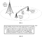
- a microwave or millimeter wave band may be applied to a wireless backhaul connection, and the band used for the wireless connection and a band in which the SCell is located may be the same or different. Referring to FIG. 1, FIG. 1, FIG.
- FIG. 1 is a schematic diagram of an application scenario of the physical downlink control channel transmission method according to the embodiments of the present invention.
- the PCell and The SCell are non-co-located, and the coverage area of the SCell is within the coverage area of the PCell.
- the SCell uses a millimeter wave high frequency band carrier to provide a service for UE.
- a PCell base station and an SCell base station may be connected by using a fiber or by means of wireless backhaul.
- the technical solutions disclosed in the embodiments of the present invention may also be used in an LTE single carrier transmission technology.
- the technical solutions may be used in an LTE system in which a cell in a millimeter wave high frequency band is used to provide a service for UE, or an LTE system in which a cell in a low frequency band of at least 6GHz is used to provide a service for UE by using a narrow beam.
- the method disclosed in the embodiments of the present invention is also applicable to a wireless communications system in which different services are transmitted on a same carrier.
- a type of service or some services may use a type of air interface feature, and another type of service or some other services may use another different air interface feature.
- each type of service or each type of air interface feature is transmitted by occupying a specified radio resource.
- UE may receive, by detecting a synchronization signal or a broadcast signal, an air interface feature corresponding to a service that needs to be received, and receive control information that is of the service or the air interface feature and that is sent by a base station, so as to receive data of the service.
- a network architecture and a service scenario described in the embodiments of the present invention are intended to describe the technical solutions in the embodiments of the present invention more clearly, but are not construed as a limitation on the technical solutions provided in the embodiments of the present invention.
- a person of ordinary skill in the art may understand that, with evolution of the network architecture and emergence of a new service scenario, the technical solutions provided in the embodiments of the present invention are also applicable to a similar technical problem.
- the embodiments of the present invention may be applied to both a time division duplex (TDD) scenario and a frequency division duplex (FDD) scenario.
- TDD time division duplex
- FDD frequency division duplex
- the embodiments of the present invention may be applied to both an LTE network and another wireless communications network.
- a corresponding name may be replaced with a name of a corresponding function in the another wireless communications network.
- Embodiment 1 of the present invention provides a physical downlink control channel transmission method, and the method is applied to a first wireless network device.
- the first wireless network device sends N signal sets, each signal set is used to transmit control information of one or more second wireless network devices, N is an integer greater than 2, and a signal in the signal set includes a PDCCH or a PDCCH and a PCFICH.
- FIG. 2 is a schematic flowchart of Embodiment 1 according to the present invention. As shown in FIG. 2 , the technical solution disclosed in this embodiment of the present invention includes the following step: S101.
- the first wireless network device sends each signal set to the second wireless network device on a resource that can be occupied by the signal set, where the first wireless network device performs sending processing on a signal in each signal set, and the sending processing includes at least one of multiplexing, scrambling, modulation, interleaving, or resource mapping.
- the method is particularly applicable to a communications system in which transmission is performed by using a narrow beam.
- the first wireless network device may send each signal set by using an antenna beam or a virtual antenna port.
- a beam 1 is corresponding to one or more antennas or virtual antennas a1, a2, and a3, and a beam 2 is corresponding to one or more antennas or virtual antennas b1 and b2.
- the virtual antenna is an antenna formed after multiple antennas are weighted. Beams are classified into an analog beam and a digital beam according to a forming manner.
- the analog beam is a beam formed in a radio frequency by using an analog device, for example, a phase shifter, a delay unit, or a waveguide.
- the analog beam cannot change after the analog beam is formed, and only a beam direction can be changed. Consequently, adaptive control of a beam is difficult to implement.
- the digital beam is a beam implemented on a baseband by using a complex-weighting method in a digital technology.
- the digital beam retains all information about an antenna array unit signal.
- An antenna array signal is processed by using an advanced digital signal processing technology, and therefore has good beam performance.
- a hybrid beam is a beam that combines the analog beam and the digital beam. In this case, there may be a correspondence between an identifier of a beam and an identifier of a signal set.
- a signal set there may be a correspondence between a signal set and a synchronization signal set.
- One synchronization signal set may be corresponding to one signal set in this embodiment of the present invention, or one synchronization signal set is corresponding to multiple signal sets, or multiple synchronization signal sets are corresponding to one signal set.
- a synchronization signal in the cell is also transmitted by using different beams. For example, eight synchronization signal sets are sent in one cell.
- the first wireless network device determines a resource that can be occupied by each signal set, and the resource of each signal set includes subcarriers of one or more resource blocks (RB, Resource Block) in a frequency domain, and includes one or more symbols in a time domain.
- Resources occupied by different signal sets do not overlap, to avoid mutual interference.
- LTE system full bandwidth is 20 M and includes 110 RBs. If the system full bandwidth is divided into 10 frequency sub-bands, each frequency sub-band includes subcarriers of 11 consecutive RBs, and each signal set may be transmitted by occupying different frequency sub-bands. For example, if the first wireless network device sends five signal sets, and the 10 frequency sub-bands are allocated to the five signal sets, each signal set may occupy two frequency sub-bands.
- Each signal set may occupy a frequency sub-band resource in various manners.
- each signal set may occupy an average resource, or the signal sets may occupy different quantities of frequency sub-band resources.
- each signal set may occupy two frequency sub-bands, that is, occupy subcarriers of 22 RBs.
- resources that can be occupied by each signal set may be consecutive or inconsecutive.
- each of the five signal sets occupies two inconsecutive frequency sub-bands.
- a base station may allocate same frequency sub-bands of all time domain symbols to a same signal set, or may allocate same frequency sub-bands of all time domain symbols to different signal sets.
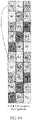
- FIG. 3-a is a schematic diagram of a case in which same frequency sub-bands of all time domain symbols are allocated to a same signal set.
- FIG. 3-b is a schematic diagram of a case in which same frequency sub-bands of all time domain symbols are allocated to different signal sets.
- FIG. 3-b in three time domain symbols occupied by a PDCCH, same frequency sub-bands of all PDCCH time domain symbols are allocated to different signal sets. It may be learned, from FIG.
- a signal set 0 occupies a first frequency sub-band and a sixth frequency sub-band of a first time domain symbol
- the signal set 0 occupies a fifth frequency sub-band and a tenth frequency sub-band of a second time domain symbol
- the signal set 0 occupies a fourth frequency sub-band and a ninth frequency sub-band of a third time domain symbol
- the signal set 0 occupies different frequency sub-bands of all the time domain symbols.
- the first wireless network device may first determine a second wireless network device that needs to be scheduled for each signal set, so as to send a PCFICH and a PDCCH to the second wireless network device.
- the PDCCH in the signal set is used to transmit control information that is used to schedule the second wireless network device.
- a base station schedules the UE in a cell that is accessed by the UE.
- the first wireless network device may determine a received signal set of the second wireless network device by using an uplink signal sent by the second wireless network device, and schedule the second wireless network device.
- Specific implementation may be determined according to an actual situation. This is not specified in the present invention.
- the first wireless network device After determining the received signal set of the second wireless network device that needs to be scheduled, the first wireless network device performs resource scheduling on the second wireless network device for receiving each signal set according to information such as data caching and channel quality, generates control information according to a scheduling result, and then generates a PDCCH according to the control information.
- a total quantity of resources occupied by a PDCCH that is in each signal set and that is used to schedule the second wireless network device does not exceed a maximum quantity of resources that can be occupied by the PDCCH in the signal set.
- the first wireless network device calculates resources occupied by the PDCCH that is in each signal set and that is used to schedule the second wireless network device, so as to obtain a quantity of time domain symbols occupied by the PDCCH transmitted in each signal set. Because quantities of different second wireless network devices scheduled for all signal sets are different and control information formats are different, the quantities of time domain symbols occupied by the PDCCHs in all the signal sets may be different.
- a quantity of symbols occupied by a PDCCH in a signal set in each subframe may be changeable or may be fixed.
- the first wireless network device may send, to the second wireless network device by using a control format indicator (CFI ) in a PCFICH in each signal set, information about the quantity of time domain symbols occupied by the PDCCH in each signal set.
- CFI control format indicator
- a PCFICH in each signal set occupies a first time domain symbol of a resource of the signal set, and may be distributed on one frequency sub-band of the signal set or may be evenly distributed on multiple frequency sub-bands in the frequency domain.
- the first wireless network device may notify, by using the PCFICH, the second wireless network device of the quantity of symbols occupied by the PDCCH in the signal set, or may notify the second wireless network device by using a system broadcast message or an RRC message, or the quantity of symbols occupied by the PDCCH in the signal set is a preset quantity of symbols.
- a PCFICH in each signal set is used to indicate a quantity of time domain symbols occupied by a PDCCH in the signal set.
- the system broadcast message or the RRC message is used to indicate a quantity of time domain symbols occupied by a PDCCH in each signal set, or a quantity of time domain symbols occupied by a PDCCH in each signal set is a preset quantity of time domain symbols.
- the first wireless network device After determining the time domain symbols occupied by the PDCCH in each signal set, the first wireless network device sends the PDCCH in each signal set by using a resource of the signal set.
- the first wireless network device performs at least one of multiplexing, scrambling, modulation, interleaving, or resource mapping on the PDCCH in each signal set. For example, the first wireless network device multiplexes a PDCCH bit of each signal set, to obtain a PDCCH bit sequence of each signal set, then performs scrambling, modulation, and symbol interleaving on the PDCCH bit sequence of each signal set, and finally maps, for sending, interleaved PDCCH data to a resource that can be occupied by each signal set.
- a CCE that can be occupied by a PDCCH in each signal set is independently numbered
- search space of each signal set at a CCE aggregation level L is defined according to a candidate PDCCH set in the signal set
- the candidate PDCCH set in each signal set is determined according to a CCE number of the signal set.
- the first wireless network device performs resource scheduling on a second wireless network device for receiving each signal set according to search space of the signal set.
- the second wireless network device determines a received signal set to send an uplink signal, and detects and receives a PDCCH (or a PHICH and a PDCCH) on a resource of the received signal set
- the first wireless network device sends information or a signal to the second wireless network device, so as to notify the second wireless network device of the received signal set and the resource that can be occupied by the received signal set.
- the resource that can be occupied by each signal set is distributed within system bandwidth and a time domain symbol occupied by the PDCCH in the signal set.
- the first wireless network device may send a cell-specific reference signal (CRS), and the second wireless network device determines the received signal set by detecting the CRS; or the first wireless network device notifies the second wireless network device of the received signal set by sending an RRC message.
- CRS cell-specific reference signal
- the first wireless network device may notify, by using different methods, the second wireless network device of the resource that can be occupied by the received signal set. For example, the first wireless network device sends a size of a frequency sub-band and a total quantity of signal sets or a total quantity of frequency sub-bands and a total quantity of signal sets to the second wireless network device. The size of the frequency sub-band and the total quantity of signal sets or the total quantity of frequency sub-bands and the total quantity of signal sets are used by the second wireless network device to calculate, according to a predefined resource allocation algorithm, the resource that can be occupied by the received signal set.
- the frequency sub-band includes one or more RBs.
- the first wireless network device may send the CRS, and the second wireless network device determines, by detecting the CRS, the resource that can be occupied by the received signal set.
- the first wireless network device notifies, by sending a PCFICH, the second wireless network device of the resource that can be occupied by the received signal set.
- the first wireless network device notifies, by sending the RRC message to the second wireless network device, the resource that is occupied by the received signal set.
- the second wireless network device may calculate, according to the predefined resource allocation algorithm, the resource that can be occupied by each signal set. Then the second wireless network device determines the received signal set by detecting the CRS sent by the first wireless network device, or determines the received signal set by receiving the RRC message sent by the first wireless network device, so as to determine the resource that can be occupied by the received signal set.
- the second wireless network device determines the received signal set by detecting the CRS sent by the first wireless network device, or determines the received signal set by receiving the RRC message sent by the first wireless network device. Then the second wireless network device detects a PCFICH in the received signal set to determine a frequency sub-band occupied by the received signal set.
- the second wireless network device detects the CRS sent by the first wireless network device, so as to determine the received signal set, or determines the received signal set by receiving the RRC message sent by the first wireless network device, and may further determine, by detecting the CRS sent by the first wireless network device, the resource that can be occupied by the received signal set.
- the first wireless network device may send no indication information or signal to the second wireless network device, and the second wireless network device independently detects the resource that can be occupied by the received signal set. If the second wireless network device successfully receives a signal set, it is considered that the currently received signal set is the received signal set, and a currently detected resource is the resource that can be occupied by the received signal set.
- the second wireless network device may perform receiving processing on a signal in the signal set on the resource of the received signal set, that is, execute an inverse process of the sending processing of the first wireless network device.
- the receiving processing may include at least one of determining search space, de-interleaving, demodulation, or descrambling.
- the technical solution of the present invention is applied to a wireless communications system in which each service occupies a specified radio resource, and transmission is performed by using a specified air interface feature (for example, a specified subcarrier spacing and/or a specified CP length), the first wireless network device does not need to send the foregoing information or signal to the second wireless network device to notify the second wireless network device of the received signal set and the resource that can be occupied by the received signal set.
- a specified air interface feature for example, a specified subcarrier spacing and/or a specified CP length
- the UE may determine, by detecting a synchronization signal, a synchronization signal of a service that needs to be received, determine an air interface feature corresponding to the received service, and determine, by receiving the broadcast channel, a radio resource occupied by the service or the air interface feature, so as to receive a PDCCH (or a PHICH and a PDCCH) that is of the service or the air interface feature and that is sent by the base station, and receive data of the service.
- a PDCCH or a PHICH and a PDCCH
- interference between signal sets sent by using a narrow beam may be canceled, PDCCH (or PCFICH and PDCCH) transmission reliability may be improved, and the second wireless network device receives the PDCCH (or the PCFICH and the PDCCH) on the resource that can be occupied by the received signal set, so as to reduce complexity of detecting a signal by the second wireless network device.
- a problem of transmitting a PDCCH (or a PDCCH and a PHICH) when different services are transmitted on a same carrier in the communications system different air interface features may be used for different services, and each signal set is corresponding to one type of service or one type of air interface feature may be further resolved.
- Embodiment 2 disclosed in the present invention provides a physical downlink control channel transmission method.
- FIG. 4 is a schematic flowchart of the physical downlink control channel transmission method according to Embodiment 2 of the present invention. As shown in FIG. 4 , the method may include the following steps.
- a first wireless network device multiplexes a PDCCH bit of each signal set.
- the first wireless network device determines a received signal set of a second wireless network device, schedules the second wireless network device according to information such as data caching and channel quality, generates control information and adds CRC information after the control information is generated, scrambles the CRC information by using a radio network temporary identifier (RNTI), and obtains a PDCCH corresponding to the control information after performing channel encoding and rate matching.
- RNTI radio network temporary identifier
- the first wireless network device may schedule the second wireless network device according to search space of a PDCCH in each signal set, and the search space of the PDCCH in each signal set is independent of each other, and a CCE that can be occupied by the PDCCH in each signal set is independently numbered.
- Search space of a signal set at a CCE aggregation level L is defined according to a candidate PDCCH set in the signal set, and the candidate PDCCH set in the signal set is determined according to a CCE number of the signal set.
- a CCE number of each signal set is associated with search space, so that when multiple PDCCH signal sets are transmitted, the second wireless network device may correctly find, according to an identifier of a signal set of the second wireless network device, search space that needs to be monitored by the second wireless network device, so as to implement correct encoding.
- the first wireless network device may multiplex a PDCCH bit of the signal set, to obtain a PDCCH bit sequence of the signal set.
- the first wireless network device scrambles, modulates, and interleaves a PDCCH bit sequence of each signal set, to obtain a PDCCH symbol pair sequence of each signal set.
- the first wireless network device After obtaining a PDCCH bit sequence of each signal set, the first wireless network device scrambles, modulates, and interleaves the PDCCH bit sequence of the signal set, to obtain PDCCH data of the signal set.
- the second wireless network device descrambles the received PDCCH bit sequence, the foregoing c ( i ) is also used for descrambling.
- a trailing bit may be added after the PDCCH bit sequence of the signal set, so that the total quantity of bits in the PDCCH bit sequence is K ⁇ Q times the total quantity of REGs that can be occupied by the signal set.
- K is a quantity of resource elements REs included in the REG
- Q is a modulation order.
- N REG B i is a quantity of REGs occupied by the signal set i
- n B i PDCCH is a quantity of PDCCHs in the signal set i.
- the first wireless network device performs modulation and symbol interleaving on the PDCCH bit sequence of each signal set after scrambling. Specifically, a PDCCH symbol sequence of each signal set is obtained after the PDCCH bit sequence of each signal set is modulated. To map the PDCCH symbol sequence to the REG, interleaving is performed by using every K symbols in the PDCCH symbol sequence as one symbol pair, and a PDCCH symbol pair sequence w ( p ) (0),..., and w ( p ) ( M quad -1) sent by an antenna port p is obtained after interleaving. M quad is a total quantity of symbol pairs.
- the first wireless network device maps, for sending, the PDCCH symbol pair sequence of each signal set to a resource that can be occupied by the signal set.
- the first wireless network device maps, for sending, the PDCCH symbol pair sequence of each signal set to a resource that can be occupied by the signal set.
- the first wireless network device maps the PDCCH symbol pair sequence of each signal set to a REG, a resource that is occupied by the signal set first in a time domain and then in a frequency domain.
- Embodiment 2 of the present invention provides a PDCCH symbol mapping method, and the PDCCH symbol pair sequence of each signal set may be mapped according to a sequence of signal set numbers. The method may include the following steps:
- steps A01 to A13 may be further optimized.
- the first wireless network device may start to perform mapping from a subcarrier that belongs to the signal set.
- a REG mapping process when the first wireless network device determines that a subcarrier does not belong to a resource that can be occupied by the signal set, it may be determined that no RE of the subcarrier represents the start location of the REG of the signal set i , and all determining steps of time domain symbols on the subcarrier may be skipped.
- the first wireless network device sends N signal sets, each signal set is used to transmit control information of one or more second wireless network devices, and the first wireless network device performs multiplexing, scrambling, modulation, interleaving, and resource mapping on a PDCCH in each signal set. It may be learned that in the solution, interference between signal sets sent by using a narrow beam may be canceled, PDCCH transmission reliability may be improved, and the second wireless network device receives the PDCCH on a resource that can be occupied by the received signal set, so as to reduce complexity of detecting a signal by the second wireless network device.
- a problem of transmitting a PDCCH (or a PDCCH and a PHICH) when different services are transmitted on a same carrier in a communications system may be further resolved.
- Embodiment 3 of the present invention discloses a physical downlink control channel transmission method, and the method is used by a first wireless network device to send a PCFICH in a signal set to a second wireless network device.
- the first wireless network device sends the PCFICH to the second wireless network device by using a first time domain symbol of a resource that can be occupied by each signal set, and a PCFICH in each signal set occupies C REGs.
- the PCFICH in each signal set can occupy four REGs.
- the PCFICH sent in each signal set may be on one frequency sub-band occupied by the signal set.
- a PCFICH sent in each of four signal sets B0 to B3 is distributed on one frequency sub-band.
- the PCFICH sent in each signal set may be distributed on multiple frequency sub-bands occupied by the signal set.
- a PCFICH sent in each of four signal sets B0 to B3 is distributed on two frequency sub-bands.
- the first wireless network device and the second wireless network device may predefine a REG distribution rule of the PCFICH, or the first wireless network device may enable, by using a system broadcast message or an RRC message, the second wireless network device to obtain a REG distribution rule of the PCFICH.
- locations of the four REGs that are occupied by the PCFICH are determined by using the following formulas:
- locations of the four REGs that are occupied by the PCFICH may be determined by using the following formulas:
- a first REG and a second REG are distributed on a first frequency sub-band
- a third REG is distributed on a second frequency sub-band
- a fourth REG is distributed on a third frequency sub-band.
- a PCFICH in each signal set is mapped to one or more frequency sub-bands that can be occupied by the signal set, and the PCFICH in each signal set is transmitted on different resources, so as to cancel mutual interference between PCFICHs in different signal sets.
- a problem of transmitting a PDCCH (or a PDCCH and a PHICH) when different services are transmitted on a same carrier in a communications system may be further resolved.
- Embodiment 4 of the present invention provides a physical downlink control channel transmission method, and the method is applied to a second wireless network device.
- FIG. 6 is a schematic flowchart of the method provided in Embodiment 4 of the present invention. As shown in FIG. 6 , the method provided in Embodiment 4 of the present invention may include the following steps.
- the second wireless network device determines a resource that can be occupied by a received signal set, where a signal in the signal set includes a PDCCH or a PDCCH and a PCFICH, and the resource that can be occupied by the signal set is lower than system bandwidth in a frequency domain.
- a first wireless network device sends N signal sets, each signal set is used to transmit control information of one or more second wireless network devices, N is an integer greater than 2, and a signal in the signal set includes a PDCCH or a PDCCH and a PCFICH.
- the first wireless network device determines a resource that can be occupied by each signal set, different signal sets may occupy resources that do not overlap, so as to avoid mutual interference, and the resource that can be occupied by each signal set may include subcarriers of one or more RBs in the frequency domain, and include one or more symbols in a time domain.
- the resource that can be occupied by each signal set is distributed within system bandwidth and a time domain symbol occupied by the PDCCH in the signal set.
- the second wireless network device may first determine the resource that can be occupied by the received signal set, and then receive a signal in the signal set on the resource of the received signal set, so as to obtain the control information sent by the first wireless network device.
- the first wireless network device may enable, by using multiple methods, the second wireless network device to obtain the resource that can be occupied by the received signal set.
- different methods cause different implementations.
- the first wireless network device may notify the second wireless network device of a size of a frequency sub-band (or a total quantity of frequency sub-bands) and a total quantity of signal sets, and the second wireless network device determines, according to the size of the frequency sub-band (or the total quantity of frequency sub-bands) and the total quantity of signal sets by using a predefined frequency sub-band allocation algorithm, the resource that can be occupied by each signal set.
- the second wireless network device may obtain, by detecting a CRS sent by the first wireless network device, the resource that can be occupied by the received signal set.
- the second wireless network device may obtain, by receiving a PCFICH in the received signal set sent by the first wireless network device, the resource that can be occupied by the received signal set.
- the second wireless network device may obtain, by receiving an RRC message sent by the first wireless network device, the resource that can be occupied by the received signal set.
- the second wireless network device needs to determine the received signal set before determining the resource that can be occupied by the received signal set.
- the second wireless network device may determine the received signal set by using multiple methods. For example, the second wireless network device may determine the received signal set by detecting the CRS sent by the first wireless network device, or the second wireless network device may determine the received signal set by receiving the RRC message sent by the first wireless network device.
- the second wireless network device may send an uplink signal to the first wireless network device, so that a base station learns of a signal set that needs to be received by the second wireless network device, and schedules the second wireless network device.
- Specific implementation may be determined according to an actual situation, and is not specified herein.
- the first wireless network device does not need to notify, by using the foregoing methods, the second wireless network device of the received signal set and the resource that can be occupied by the received signal set.
- a specified air interface feature for example, a specified subcarrier spacing or a specified CP length
- UE may determine, by detecting a synchronization signal, a synchronization signal of a service that needs to be received, and an air interface feature corresponding to the service, and determine, by receiving a broadcast channel, a radio resource occupied by the service or the air interface feature, so as to receive a PDCCH (or a PHICH and a PDCCH) that is of the service or the air interface feature and that is sent by the base station, and receive data of the service.
- a PDCCH or a PHICH and a PDCCH
- the second wireless network device receives the signal in the signal set on the resource that can be occupied by the received signal set, so as to obtain control information sent by a first wireless network device, where receiving processing includes at least one of determining search space, de-interleaving, demodulation, or descrambling.
- the second wireless network device After determining the resource that can be occupied by the received signal set, the second wireless network device receives the signal in the signal set on the resource that can be occupied by the received signal set, so as to obtain the control information sent by the first wireless network device.
- the second wireless network device receives the PCFICH on a first symbol of the resource that can be occupied by the received signal set, the PCFICH in each signal set may be distributed on one frequency sub-band resource of the signal set, or may be distributed on multiple frequency sub-bands.
- the second wireless network device obtains, by receiving the PCFICH in each signal set, a quantity of time domain symbols occupied by a PDCCH in the signal set.
- a quantity of time domain symbols occupied by a PDCCH in a signal set is indicated by a system broadcast message or an RRC message sent by the first wireless network device, or is a preset quantity of time domain symbols
- the second wireless network device obtains, by receiving the system broadcast message or the RRC message, a quantity of time domain symbols occupied by a PDCCH in each signal set.
- the second wireless network device receives the PDCCH on the resource that can be occupied by the received signal set, and may perform processing such as at least one of determining search space, de-interleaving, demodulation, or descrambling on the received PDCCH.
- the first wireless network device determines search space of the received signal set, and performs PDCCH detection on the received signal set according to the search space, which includes operations such as de-interleaving, demodulation, and descrambling, so as to obtain the control information sent by the first wireless network device.
- the second wireless network device determines the resource that can be occupied by the received signal set, and receives the signal in the signal set on the resource that can be occupied by the received signal set, so as to obtain a control channel sent by the first wireless network device.
- the resource that can be occupied by the received signal set is lower than the system bandwidth in the frequency domain, and the received signal set and another signal set are transmitted separately, so as to cancel interference between signal sets, improve PDCCH (or PCFICH and PDCCH) transmission reliability, and reduce complexity of detecting a signal by the second wireless network device.
- a problem of transmitting a PDCCH (or a PDCCH and a PHICH) when different services are transmitted on a same carrier in the communications system may be further resolved.
- Embodiment 5 of the present invention provides a physical downlink control channel transmission method, and the method is applied to a second wireless network device.
- FIG. 7 is a schematic flowchart of the physical downlink control channel transmission method according to Embodiment 5 of the present invention. As shown in FIG. 7 , the method may include the following steps.
- the second wireless network device performs de-interleaving, demodulation, and bit descrambling on a PDCCH received on a resource that can be occupied by a received signal set.
- the second wireless network device may receive the PDCCH on the resource that can be occupied by the received signal set.
- a first wireless network device maps a PDCCH symbol of a signal set first in a time domain and then in a frequency domain. Therefore, the second wireless network device also receives the PDCCH symbol according to a similar rule. That is, the second wireless network device receives the PDCCH symbol first from a time domain REG and then from a frequency domain REG on the resource that can be occupied by the received signal set.
- K symbols received from each REG are a symbol pair. K is a quantity of REs occupied by the REG.
- the second wireless network device performs PDCCH detection according to search space of the received signal set, to obtain control information sent by a first wireless network device.
- the second wireless network device may first determine the search space of the received signal set before receiving a PDCCH in the received signal set.
- Search space of a PDCCH that is in each signal set and that is sent by the first wireless network device is independent of each other, and a CCE occupied by the PDCCH in each signal set is independently numbered.
- Search space of a signal set at a CCE aggregation level L is defined according to a candidate PDCCH set in the signal set, and the candidate PDCCH set in the signal set is determined according to a CCE number of the signal set.
- a candidate PDCCH detected by the second wireless network device may be shown in the following table, or may have another definition according to an actual situation: Search space S k L Number of PDCCH candidates M ( L ) Type Aggregation level L Size [in CCEs] UE-s pecific UE-s pecific 1 6 6 2 12 6 4 8 2 8 16 2 Com mon Com mon 4 16 4 8 16 2
- the second wireless network device detects the PDCCH in the received signal set according to the search space of the received signal set, which includes operations such as de-interleaving, demodulation, and descrambling.
- the second wireless network device may sequentially detect search space at all CCE aggregation levels. When detection succeeds, the control information sent by the first wireless network device may be obtained.
- the second wireless network device can de-interleave, demodulate, and descramble the PDCCH received on the resource that can be occupied by the received signal set, and perform PDCCH detection according to the search space of the received signal set, so as to obtain the control information sent by the first wireless network device.
- the resource that can be occupied by the received signal set is lower than system bandwidth in the frequency domain, and the received signal set and another signal set are transmitted separately, so as to cancel interference between signal sets, improve PDCCH transmission reliability, and reduce complexity of detecting a signal by the second wireless network device.
- a problem of transmitting a PDCCH (or a PDCCH and a PHICH) when different services are transmitted on a same carrier in a communications system different air interface features may be used for different services, and each signal set is corresponding to one type of service or one type of air interface feature may be further resolved.
- Embodiment 6 of the present invention provides a physical downlink control channel transmission method, and the method is applied to a second wireless network device.
- FIG. 8 is a schematic flowchart of the method provided in Embodiment 6 of the present invention. As shown in FIG. 8 , the method provided in Embodiment 6 of the present invention may include the following steps.
- the second wireless network device receives a system broadcast message or an RRC message sent by a first wireless network device, so as to obtain a size of a frequency sub-band and a total quantity of signal sets or a total quantity of frequency sub-bands and a total quantity of signal sets, where the frequency sub-band includes subcarriers of one or more RBs in a frequency domain.
- the first wireless network device in order that the second wireless network device obtains, by means of calculation according to a predefined resource allocation algorithm, a resource that can be occupied by a received signal set, the first wireless network device notifies, by using the system broadcast message or the RRC message, the second wireless network device of the size of the frequency sub-band or the total quantity of frequency sub-bands and the total quantity of signal sets.
- the second wireless network device may obtain, according to the size of the frequency sub-band (or the total quantity of frequency sub-bands) and the total quantity of signal sets by using the predefined allocation algorithm, a resource that can be occupied by each signal set, and then obtain, according to the determined received signal set, the resource that can be occupied by the received signal set.
- the second wireless network device calculates, according to a predefined resource allocation algorithm, a resource that can be occupied by each signal set.
- the second wireless network device may calculate, by using the predefined resource allocation algorithm, a frequency sub-band occupied by each signal set.
- a predefined frequency sub-band allocation algorithm is as follows: A quantity of RBs on each frequency sub-band is represented by S BW , a total quantity of frequency sub-bands into which downlink system bandwidth may be divided is: and the frequency sub-bands are numbered as S i in ascending order or in descending order of frequencies.
- N RB DL is downlink system bandwidth
- a value of S i ranges from 0 to ( ⁇ N RB DL / S BW ⁇ ⁇ 1 ) (including 0 and ( ⁇ N RB DL / S BW ⁇ ⁇ 1 ) ). If a total quantity S N of frequency sub-bands is sent by the first wireless network device, it is calculated, according to S N , that a size of each frequency sub-band is and the frequency sub-bands are numbered as S i in ascending order or in descending order of frequencies. A value of S i ranges from 0 to ( S N -1).
- N beamnum is a quantity of sent signal sets. Assuming that N beamnum is 5, and a total quantity of frequency sub-bands is 10, a calculation result is shown in FIG. 3-a .
- an identifier, of a signal set, of a frequency sub-band S i on a time domain symbol l i may be obtained by means of calculation according to a formula ( S i + l i ) mod N beamsum .
- l i is a time domain symbol number. Assuming that N beamnum is 5, and a total quantity of frequency sub-bands is 10, a calculation result is shown in FIG. 3-b . It may be learned that the second wireless network device may calculate, according to the foregoing algorithm, a frequency sub-band that can be occupied by each signal set.
- the resource that can be occupied by the received signal set is distributed within system bandwidth and a time domain symbol occupied by a PDCCH in the signal set.
- the second wireless network device may obtain, according to the foregoing algorithm, a frequency sub-band that can be occupied on each time domain symbol of a signal set.
- the second wireless network device detects a CRS sent by the first wireless network device, or receives the RRC message sent by the first wireless network device, so as to determine a received signal set.
- the second wireless network device After determining a resource that can be occupied by each signal set, the second wireless network device needs to determine the received signal set to determine the resource that can be occupied by the received signal set.
- a resource location of the CRS or a sequence of the CRS sent by the first wireless network device on a resource that can be occupied by each signal set is related to an identifier of the signal set, and the second wireless network device may determine the received signal set by detecting the CRS.
- the resource location of the CRS sent by the first wireless network device is related to an identifier of a signal set
- the second wireless network device may learn of, by detecting a location of the CRS, an identifier of a signal set that occupies a resource for sending the CRS.
- the second wireless network device may determine, as an identifier of the received signal set, an identifier that is of a signal set and that is detected on a resource on which quality of receiving the CRS is highest.
- the sequence of the CRS sent by the first wireless network device is related to an identifier of a signal set
- the second wireless network device may learn of, by detecting the sequence of the CRS, an identifier of a signal set that occupies a resource for sending the CRS.
- the second wireless network device calculates the value c init of the foregoing pseudorandom sequence initialization formula by using a detected sequence of the CRS, and calculates N ID new by using the value of the formula, so as to obtain the identifier of the signal set by means of calculation according to a relationship among N ID new , the physical cell identifier, and the identifier of the signal set.
- the second wireless network device may determine, as an identifier of the received signal set, an identifier that is of a signal set and that is detected on a resource on which quality of receiving the CRS is highest.
- the second wireless network device obtains an identifier of the received signal set by using an RRC message sent by the first wireless network device.
- the second wireless network device receives a signal in a signal set on a resource that can be occupied by the received signal set, so as to obtain control information sent by the first wireless network device, where receiving processing includes at least one of determining search space, de-interleaving, demodulation, or descrambling.
- the second wireless network device After determining the resource that can be occupied by the received signal set, the second wireless network device receives the signal in the signal set on the resource that can be occupied by the received signal set, so as to obtain the control information sent by the first wireless network device.
- this step refer to step S402 in Embodiment 4 of the present invention. This is not described again.
- the second wireless network device calculates, by using the predefined resource allocation algorithm, the resource that can be occupied by each signal set, and determines, according to the identifier of the received signal set, the resource that can be occupied by the received signal set, so as to receive a signal in the received signal set to obtain a control channel sent by the first wireless network device.
- the resource that can be occupied by the received signal set is lower than the system bandwidth in the frequency domain, and the received signal set and another signal set are transmitted separately, so as to cancel interference between signal sets sent by using a narrow-band beam, improve PDCCH (or PCFICH and PDCCH) transmission reliability, and reduce complexity of detecting a signal by the second wireless network device.
- Embodiment 7 of the present invention provides a physical downlink control channel transmission method, and the method is applied to a second wireless network device.
- FIG. 9 is a schematic flowchart of the method provided in Embodiment 7 of the present invention. As shown in FIG. 9 , the method provided in Embodiment 7 of the present invention may include the following steps.
- the second wireless network device detects a CRS sent by a first wireless network device, or receives an RRC message sent by a first wireless network device, so as to determine a received signal set.
- the second wireless network device may determine, by detecting a PCFICH in a received signal set sent by the first wireless network device, a resource that can be occupied by the received signal set.
- a REG location of the PCFICH in the signal set is related to an identifier of the received signal set. Therefore, the second wireless network device may first determine the identifier of the received signal set, so as to determine the resource that can be occupied by the received signal set.
- step S603 For specific implementation of detecting the CRS sent by the first wireless network device, so as to determine the received signal set, refer to step S603 in Embodiment 6 of the present invention. This is not described again.
- the second wireless network device determines, by detecting a PCFICH in the received signal set sent by the first wireless network device, a resource that can be occupied by the received signal set.
- the second wireless network device may receive the PCFICH in the received signal set according to the identifier of the signal set.
- the second wireless network device may determine, by using the PCFICH, the resource that can be occupied by the received signal set, and may further obtain, by using a CFI in the PCFICH, a quantity of time domain symbols occupied by a PDCCH in the received signal set.
- a PCFICH in each signal set may carry M pieces of bit information to indicate a frequency sub-band occupied by the signal set.
- Each bit is corresponding to one frequency sub-band. That a bit value is 1 represents that a signal set occupies the frequency sub-band, and a bit 0 represents that no signal set occupies the frequency sub-band.
- the first wireless network device may jointly encode the M pieces of bit information and the CFI information of the PCFICH, and obtain K ⁇ Q ⁇ C pieces of bit information after encoding and scramble the K ⁇ Q ⁇ C pieces of bit information, or may scramble, by using the M pieces of bit information, K ⁇ Q ⁇ C bits obtained after encoding the CFI information.
- K is a quantity of REs occupied by a REG
- Q is a modulation order
- C is a quantity of REGs occupied by the PCFICH in the signal set.
- the second wireless network device may obtain the M pieces of bit information in a corresponding process such as descrambling or decoding.
- the resource that can be occupied by the received signal set is distributed within system bandwidth and a time domain symbol occupied by the PDCCH in the signal set. If the received signal set occupies a same frequency sub-band on each time domain symbol that can be occupied, the second wireless network device may obtain, by using the foregoing method, the resource that can be occupied by the received signal set.
- the second wireless network device receives a signal in the signal set on the resource that can be occupied by the received signal set, so as to obtain control information sent by the first wireless network device, where receiving processing includes at least one of determining search space, de-interleaving, demodulation, or descrambling.
- the second wireless network device After determining the resource that can be occupied by the received signal set, the second wireless network device receives the signal in the signal set on the resource that can be occupied by the received signal set, so as to obtain the control information sent by the first wireless network device.
- this step refer to step S402 in Embodiment 4 of the present invention. This is not described again.
- the second wireless network device determines, by detecting the PCFICH in the received signal set sent by the first wireless network device, the resource that can be occupied by the received signal set, so as to receive the signal in the received signal set, and obtain a control channel sent by the first wireless network device.
- the resource that can be occupied by the received signal set is lower than the system bandwidth in a frequency domain, and the received signal set and another signal set are transmitted separately, so as to cancel interference between signal sets sent by using a narrow-band beam, improve PDCCH (or PCFICH and PDCCH) transmission reliability, and reduce complexity of detecting a signal by the second wireless network device.
- Embodiment 8 of the present invention provides a physical downlink control channel transmission method, and the method is applied to a second wireless network device.
- FIG. 10 is a schematic flowchart of the method provided in Embodiment 8 of the present invention. As shown in FIG. 10 , the method provided in Embodiment 8 of the present invention may include the following steps.
- the second wireless network device detects a CRS sent by a first wireless network device, or receives an RRC message sent by a first wireless network device, so as to determine a received signal set, and determines, by detecting the CRS sent by the first wireless network device, a resource that can be occupied by the received signal set.
- the second wireless network device determines an identifier of the received signal set, and then determines the resource that can be occupied by the received signal set.
- the second wireless network device may directly determine, by detecting the CRS, the received signal set and the resource that can be occupied by the received signal set.
- the second wireless network device may detect the CRS within system bandwidth and a time domain symbol occupied by a PDCCH in the received signal set, so as to determine the received signal set and the resource that can be occupied by the received signal set.
- detecting the CRS sent by the first wireless network device so as to determine the received signal set, refer to step S603 in Embodiment 6 of the present invention. This is not described again.
- a resource location of a CRS or a sequence of a CRS sent by the first wireless network device on a resource that can be occupied by each signal set is related to an identifier of the signal set.
- the second wireless network device may determine, by detecting the resource location of the CRS or the sequence of the CRS, an identifier of a signal set that occupies a resource for sending the CRS. After determining the identifier of the received signal set, the second wireless network device may use, as the resource that can be occupied by the received signal set, a resource on which the identifier of the received signal set is detected in the resource for sending the CRS.
- the second wireless network device receives a signal in the signal set on the resource that can be occupied by the received signal set, so as to obtain control information sent by the first wireless network device, where receiving processing includes at least one of determining search space, de-interleaving, demodulation, or descrambling.
- the second wireless network device After determining the resource that can be occupied by the received signal set, the second wireless network device receives the signal in the signal set on the resource that can be occupied by the received signal set, so as to obtain the control information sent by the first wireless network device.
- this step refer to step S402 in Embodiment 4 of the present invention. This is not described again.
- the second wireless network device determines, by detecting the CRS, the resource that can be occupied by the received signal set, and receives the signal in the signal set on the resource that can be occupied by the received signal set, so as to obtain the control information sent by the first wireless network device.
- the resource that can be occupied by the received signal set is lower than the system bandwidth in a frequency domain, and the received signal set and another signal set are transmitted separately, so as to cancel interference between signal sets sent by using a narrow-band beam, improve PDCCH (or PCFICH and PDCCH) transmission reliability, and reduce complexity of detecting a signal by the second wireless network device.
- Embodiment 9 of the present invention provides a wireless network device, configured to send N signal sets. Each signal set is used to transmit control information of one or more second wireless network devices, N is an integer greater than 2, and a signal in the signal set includes a PDCCH or a PDCCH and a PCFICH.
- the wireless network device 900 may include a sending unit 910.
- the sending unit 910 is configured to send each signal set to the second wireless network device on a resource that can be occupied by the signal set, where the sending unit performs sending processing on a signal in each signal set, and the sending processing includes at least one of multiplexing, scrambling, modulation, interleaving, or resource mapping.
- the sending unit 910 is specifically configured to send a PDCCH in the signal set to the second wireless network device by using the resource that can be occupied by the signal set.
- a quantity of time domain symbols occupied by the PDCCH in the signal set is a quantity of time domain symbols notified by the first wireless network device to the second wireless network device by using a system broadcast message or an RRC message, or is a preset quantity of time domain symbols.
- the sending unit 910 is specifically configured to send a PCFICH in each signal set to the second wireless network device by using a first time domain symbol of the resource that can be occupied by the signal set, where the PCFICH is used to indicate a quantity of time domain symbols occupied by the PDCCH in the signal set; and is further configured to send the PDCCH in the signal set to the second wireless network device by using the resource that can be occupied by the signal set, where a quantity of time domain symbols occupied by the PDCCH in the signal set is a quantity of time domain symbols indicated by the PCFICH in the signal set.
- a CCE that can be occupied by each signal set is independently numbered
- search space of the signal set at a CCE aggregation level L is defined according to a candidate PDCCH set in the signal set
- the candidate PDCCH set in the signal set is determined according to a CCE number of the signal set.
- the sending unit 910 sends the PCFICH to the second wireless network device by using four REGs in a first time domain symbol of the resource that can be occupied by each signal set. If the REGs are distributed on one frequency sub-band occupied by the signal set, one frequency sub-band includes subcarriers of one or more resource blocks RBs, and subcarrier locations of the REGs are expressed as:
- the wireless network device 900 may further include an indication unit 920.
- the indication unit 920 is configured to send a CRS, where a resource location of the CRS or a sequence of the CRS is used to notify the second wireless network device of the received signal set, or is configured to send an RRC message to notify the second wireless network device of the received signal set.
- the indication unit 920 is further configured to send a size of a frequency sub-band and a total quantity of signal sets or a total quantity of frequency sub-bands and a total quantity of signal sets to the second wireless network device, where the size of the frequency sub-band and the total quantity of signal sets or the total quantity of frequency sub-bands and the total quantity of signal sets are used by the second wireless network device to calculate, according to a predefined resource allocation algorithm, the resource that can be occupied by the received signal set, and one frequency sub-band includes subcarriers of one or more RBs in a frequency domain; or is further configured to send a CRS, where a resource location of the CRS or a sequence of the CRS is used by the second wireless network device to determine the resource that can be occupied by the received signal set; or is further configured to send a PCFICH to notify the second wireless network device of the resource that can be occupied by the received signal set; or is further configured to send an RRC message to the second wireless network device to notify the second wireless network device of the resource
- the indication unit 920 notifies, by using M pieces of bit information included in the PCFICH in the signal set, the second wireless network device of the resource that can be occupied by the received signal set.
- M is the total quantity of frequency sub-bands, and each bit in the M pieces of bit information indicates whether one frequency sub-band belongs to the resource that can be occupied by the signal set.
- the indication unit 920 may not notify, by using the foregoing methods, the second wireless network device of the received signal set and the resource that can be occupied by the received signal set. In this case, the indication unit 920 is configured to send a synchronization signal to the second wireless network device.
- a specified air interface feature for example, a specified subcarrier spacing and/or a specified CP length
- the synchronization signal is used by the second wireless network device to determine a synchronization signal of a service that needs to be received, and the indication unit 920 may be further configured to send the system broadcast message to notify the second wireless network device of a radio resource occupied by the service or an air interface feature corresponding to the service.
- interference between signal sets sent by using a narrow beam may be canceled, PDCCH (or PCFICH and PDCCH) transmission reliability may be improved, and the second wireless network device receives a PDCCH (or a PCFICH and a PDCCH) on the resource that can be occupied by the received signal set, so as to reduce complexity of detecting a signal by the second wireless network device.
- a problem of transmitting a PDCCH (or a PDCCH and a PHICH) when different services are transmitted on a same carrier (different air interface features are used for different services) in the communications system, and each signal set is corresponding to one type of service or one type of air interface feature may be further resolved.
- Embodiment 10 of the present invention provides a wireless network device, to implement a physical downlink control channel transmission method disclosed in the embodiments of the present invention, that is, to obtain control information from a first wireless network device.
- the wireless network device a00 may include a processing unit a10 and a receiving unit a20.
- the processing unit a10 is configured to determine a resource that can be occupied by a received signal set.
- the signal set may include a PDCCH or a PDCCH and a PCFICH, and the resource that can be occupied by the signal set is lower than system bandwidth in a frequency domain.
- the receiving unit a20 is configured to receive a signal in the signal set on the resource that can be occupied by the received signal set, so as to obtain control information sent by the first wireless network device, where receiving processing includes at least one of determining search space, de-interleaving, demodulation, or descrambling.
- the receiving unit a20 is specifically configured to receive the PDCCH in the signal set on the resource that can be occupied by the received signal set, so as to obtain the control information sent by the first wireless network device.
- a quantity of time domain symbols occupied by the PDCCH in the received signal set is a quantity that is of time domain symbols occupied by the signal set and that is indicated in a system broadcast message or an RRC message sent by the first wireless network device, or is a preset quantity of time domain symbols.
- the receiving unit a20 is specifically configured to receive the PCFICH in the signal set on a first time domain symbol of the resource that can be occupied by the received signal set; and is further specifically configured to receive the PDCCH in the signal set on the resource that can be occupied by the received signal set, so as to obtain the control information sent by the first wireless network device.
- a quantity of time domain symbols occupied by the PDCCH in the received signal set is a quantity of time domain symbols indicated by the PCFICH in the signal set.
- the processing unit a10 is configured to calculate, according to a size of a frequency sub-band and a total quantity of signal sets or according to a total quantity of frequency sub-bands and a total quantity of signal sets by using a predefined resource allocation algorithm, the resource that can be occupied by the received signal set, where one frequency sub-band includes subcarriers of one or more RBs in the frequency domain, and the size of the frequency sub-band and the total quantity of signal sets or the total quantity of frequency sub-bands and the total quantity of signal sets are obtained from the system broadcast message or the RRC message sent by the first wireless network device; or is specifically configured to determine, by detecting the PCFICH in the received signal set sent by the first wireless network device, the resource that can be occupied by the received signal set; or is specifically configured to detect a CRS sent by the first wireless network device, and determine, according to a resource location of the CRS or a sequence of the CRS, the resource that can be occupied by the received signal set; or is specifically configured to determine,
- the processing unit a10 does not need to determine, by using the foregoing methods, the received signal set and the resource that can be occupied by the received signal set. In this case, the processing unit a10 determines, by detecting a synchronization signal, a synchronization signal of a service that needs to be received, and determines, by receiving the broadcast channel sent by the first wireless network device, a radio resource occupied by the service or the air interface feature.
- a specified air interface feature for example, a specified subcarrier spacing and/or a specified CP length
- a second wireless network device determines the resource that can be occupied by the received signal set, and receives the signal in the signal set on the resource that can be occupied by the received signal set, so as to obtain a control channel sent by the first wireless network device.
- the resource that can be occupied by the received signal set is lower than the system bandwidth in the frequency domain, and the received signal set and another signal set are transmitted separately, so as to cancel interference between signal sets, improve PDCCH (or PCFICH and PDCCH) transmission reliability, and reduce complexity of detecting a signal by the second wireless network device.
- a problem of transmitting a PDCCH (or a PDCCH and a PHICH) when different services are transmitted on a same carrier in the communications system may be further resolved.
- an embodiment of the present invention further provides a physical downlink control channel transmission apparatus, that is, a wireless network device 10.
- the wireless network device 10 is corresponding to the first wireless network device in the foregoing physical downlink control channel transmission method.
- the first wireless network device may be a base station, or may be another device.
- the wireless network device 10 includes a processor 110, a memory 120, a bus system 130, a receiver 140, and a transmitter 150.
- the processor 110, the memory 120, the receiver 140, and the transmitter 150 are connected by using the bus system 130.
- the memory 120 is configured to store an instruction.
- the processor 110 is configured to: execute the instruction stored in the memory 120, so as to control the receiver 140 to receive a signal and control the transmitter 150 to send a signal; and complete steps in the foregoing physical downlink control channel transmission method.
- the receiver 140 and the transmitter 150 may be a same physical entity or different physical entities. When the receiver 140 and the transmitter 150 are a same physical entity, the receiver 140 and the transmitter 150 may be collectively referred to as a transceiver.
- functions of the receiver 140 and the transmitter 150 are implemented by using a transceiver circuit or a dedicated transceiver chip.
- the processor 110 is implemented by using a dedicated processing chip, a processing circuit, a processor, or a general purpose chip.
- the physical downlink control channel transmission apparatus provided in this embodiment of the present invention is implemented by using a general purpose computer. That is, program code for implementing functions of the processor 110, the receiver 140, and the transmitter 150 are stored in the memory, and the general purpose processor implements the functions of the processor 110, the receiver 140, and the transmitter 150 by executing the code in the memory.
- an embodiment of the present invention further provides another physical downlink control channel transmission apparatus, that is, a wireless network device 20.
- the wireless network device 20 is corresponding to the second wireless network device in the foregoing physical downlink control channel transmission method.
- the second wireless network device may be user equipment, or may be a micro base station, a small cell, or a relay.
- the wireless network device includes a processor 210, a memory 220, a bus system 230, a receiver 240, and a transmitter 250.
- the processor 210, the memory 220, the receiver 240, and the transmitter 250 are connected by using the bus system 230.
- the memory 220 is configured to store an instruction.
- the processor 210 is configured to: execute the instruction stored in the memory 220, so as to control the receiver 240 to receive a signal and control the transmitter 250 to send a signal; and complete steps in the foregoing physical downlink control channel transmission method.
- the receiver 240 and the transmitter 250 may be a same physical entity or different physical entities. When the receiver 240 and the transmitter 250 are a same physical entity, the receiver 240 and the transmitter 250 may be collectively referred to as a transceiver.
- functions of the receiver 240 and the transmitter 250 are implemented by using a transceiver circuit or a dedicated transceiver chip. It may be considered that the processor 210 is implemented by using a dedicated processing chip, a processing circuit, a processor, or a general purpose chip.
- the physical downlink control channel transmission apparatus provided in this embodiment of the present invention is implemented by using a general purpose computer. That is, program code for implementing functions of the processor 210, the receiver 240, and the transmitter 250 are stored in the memory, and the general purpose processor implements the functions of the processor 210, the receiver 240, and the transmitter 250 by executing the code in the memory.
- an embodiment of the present invention further provides a communications system, including the first wireless network device and the one or more second wireless network devices described above.
- the processor 110 or 210 may be a central processing unit (Central Processing Unit, "CPU” for short), or the processor may be another general purpose processor, a digital signal processor (DSP), an application-specific integrated circuit (ASIC), a field-programmable gate array (FPGA) or another programmable logic device, a discrete gate or a transistor logic device, a discrete hardware component, or the like.
- the general purpose processor may be a microprocessor, or the processor may be any conventional processor, or the like.
- the memory 120 or 220 may include a read-only memory and a random access memory, and provide an instruction and data for the processor 110 or 210.
- a part of the memory may further include a nonvolatile random access memory.
- the memory may further store information about a device type.
- the bus system 130 or 230 may include a power bus, a control bus, a status signal bus, and the like. However, for clarity of description, various buses are marked as the bus system in the figure.
- steps of the foregoing methods may be completed by using an integrated logic circuit of hardware in the processor 110 or 210 or an instruction in a form of software.
- the steps of the methods disclosed with reference to the embodiments of the present invention may be directly performed by a hardware processor, or may be performed by using a combination of hardware in the processor and a software module.
- the software module may be located in a mature storage medium in the art, such as a random access memory, a flash memory, a read-only memory, a programmable read-only memory, an electrically erasable programmable memory, or a register.
- the storage medium is located in the memory.
- the processor reads information from the memory, and completes the steps in the foregoing methods in combination with the hardware in the processor. Details are not described again herein to avoid repetition.
- sequence numbers of the foregoing processes do not mean execution sequences in various embodiments of the present invention.
- the execution sequences of the processes should be determined according to functions and internal logic of the processes, and should not be construed as any limitation on the implementation processes of the embodiments of the present invention.
- the disclosed system, apparatus, and method may be implemented in other manners.
- the described apparatus embodiment is merely an example.
- the unit division is merely logical function division and may be other division in actual implementation.
- a plurality of units or components may be combined or integrated into another system, or some features may be ignored or not performed.
- the displayed or discussed mutual couplings or direct couplings or communication connections may be implemented by using some interfaces.
- the indirect couplings or communication connections between the apparatuses or units may be implemented in electronic, mechanical, or other forms.
- the units described as separate parts may or may not be physically separate, and parts displayed as units may or may not be physical units, may be located in one position, or may be distributed on a plurality of network units. Some or all of the units may be selected according to actual requirements to achieve the objectives of the solutions of the embodiments.
- functional units in the embodiments of the present invention may be integrated into one processing unit, or each of the units may exist alone physically, or two or more units are integrated into one unit.
- the functions When the functions are implemented in the form of a software functional unit and sold or used as an independent product, the functions may be stored in a computer-readable storage medium. Based on such an understanding, the technical solutions of the present invention essentially, or the part contributing to the prior art, or some of the technical solutions may be implemented in a form of a software product.
- the software product is stored in a storage medium, and includes several instructions for instructing a computer device (which may be a personal computer, a server, or a network device) to perform all or some of the steps of the methods described in the embodiments of the present invention.
- the foregoing storage medium includes any medium that can store program code, such as a USB flash drive, a removable hard disk, a read-only memory (ROM, Read-Only Memory), a random access memory (RAM, Random Access Memory), a magnetic disk, or an optical disc.
- program code such as a USB flash drive, a removable hard disk, a read-only memory (ROM, Read-Only Memory), a random access memory (RAM, Random Access Memory), a magnetic disk, or an optical disc.
Landscapes
- Engineering & Computer Science (AREA)
- Signal Processing (AREA)
- Computer Networks & Wireless Communication (AREA)
- Mobile Radio Communication Systems (AREA)
Claims (14)
- Übertragungsverfahren eines physikalischen "Downlink"-Steuerkanals, wobei das Verfahren von einem drahtlosen Netzwerkgerät (900) verwendet wird, um N Signalsätze zu senden, die jeweils einem anderen Netzwerkdienst entsprechen, wobei jeder der N Signalsätze verwendet wird, um Steuerinformationen eines Endgeräts zu übertragen, N eine ganze Zahl größer als 2 ist, ein Signal in jedem Signalsatz einen physikalischen "Downlink"-Steuerkanal, PDCCH, oder einen PDDCH und einen physikalischen Steuerformatindikatorkanal, PCFICH, umfasst, und wobei das Verfahren Folgendes umfasst:Senden (S 101) jedes Signalsatzes an das Endgerät auf einer Ressource, die von dem Signalsatz belegt werden kann, wobeieine Sendeverarbeitung an einem Signal in jedem Signalsatz ausgeführt wird und die Sendeverarbeitung mindestens eines von Multiplexen (S201), Scrambeln, Modulation, Interleaving (S202) oder Ressourcenabbildung (S203) umfasst.
- Verfahren nach Anspruch 1, wobei das Senden jedes Signalsatzes an das Endgerät auf einer Ressource, die von dem Signalsatz belegt werden kann, ferner Folgendes umfasst:Senden des PDCCH in dem Signalsatz an das Endgerät mit Hilfe der Ressource, die von dem Signalsatz belegt werden kann, wobeieine Menge von Zeitbereichssymbolen, die von dem PDCCH in dem Signalsatz belegt sind, eine Menge von Zeitbereichssymbolen ist, die von dem drahtlosen Netzwerkgerät (900) mit Hilfe einer System-Broadcast-Nachricht oder einer Funkressourcensteuerungs-, RRC-, Nachricht an das Endgerät gemeldet werden, oder eine voreingestellte Menge von Zeitbereichssymbolen ist.
- Verfahren nach Anspruch 1, wobei das Senden jedes Signalsatzes an das Endgerät auf einer Ressource, die von dem Signalsatz belegt werden kann, Folgendes umfasst:
Senden des PCFICH in jedem Signalsatz an das Endgerät mit Hilfe eines ersten Zeitbereichssymbols der Ressource, die von dem Signalsatz belegt werden kann, und Senden des PDCCH in dem Signalsatz an das Endgerät mit Hilfe der Ressource, die von dem Signalsatz belegt werden kann, wobei eine Menge von Zeitbereichssymbolen, die von dem PDCCH in dem Signalsatz belegt sind, eine Menge von Zeitbereichssymbolen ist, die von dem PCFICH in dem Signalsatz angegeben wird. - Verfahren nach einem der Ansprüche 1 bis 3, wobei ein Steuerkanalelement CCE, das von jedem Signalsatz belegt werden kann, unabhängig nummeriert wird, ein Suchraum des Signalsatzes auf einer CCE-Aggregationsebene L gemäß einem Kandidaten-PDCCH-Satz in dem Signalsatz definiert wird und der Kandidaten-PDCCH-Satz in dem Signalsatz gemäß einer CCE-Nummer in dem Signalsatz bestimmt wird, und der CCE-Suchraum des Signalsatzes auf der CCE-Aggregationsebene L wie folgt ausgedrückt wird:
 i=0, ..., und L-1,
 für einen gemeinsamen Suchraum Yk =0 und/oder für einen endgerätespezifischen Suchraum auf der Aggregationsebene L Yk als Yk =(A-Yk-1)modD definiert ist, A und D ganzzahlige Koeffizienten sind, Y-1 = nRNTI ≠ 0 und nRNTI eine temporäre Funknetzkennung ist.
 - Verfahren nach einem der Ansprüche 1 bis 4, wobei das Durchführen des Scrambelns an dem Signal in jedem Signalsatz Folgendes umfasst:Scrambeln einer PDCCH-Bitsequenz jedes Signalsatzes derart, dass eine gescrambelte Bitsequenz gewonnen wird, wobei die gescrambelte Bitsequenz wie folgt ausgedrückt wird:
 b(i) die PDCCH-Bitsequenz ist, die vor dem Scrambeln verwendet wurde, eine gescrambelte Sequenz c(I) zu


- Verfahren nach einem der Ansprüche 3 bis 5, wobei das Senden des PCFICH in jedem Signalsatz an das Endgerät mit Hilfe eines ersten Zeitbereichssymbols der Ressource, die von dem Signalsatz belegt werden kann, Folgendes umfasst:
Senden des PCFICH an das Endgerät mit Hilfe von vier Ressourcenelementegruppen REGs in dem ersten Zeitbereichssymbol der Ressource, die von jedem Signalsatz belegt werden kann, wobei, wenn die REGs auf einem Frequenz-Teilband verteilt sind, das von dem Signalsatz belegt ist, das Frequenzteilband Teilträger von einem oder mehreren Ressourcenblöcken RBs umfasst und Teilträgerpositionen der REGs wie folgt ausgedrückt sind:eine Teilträgerposition einer ersten REG ist: eine Teilträgerposition einer zweiten REG ist:
 eine Teilträgerposition einer dritten REG ist:
 eine Teilträgerposition einer vierten REG ist:


- Verfahren nach einem der Ansprüche 1 bis 6, wobei das Verfahren vor dem Senden jedes Signalsatzes an das Endgerät auf einer Ressource, die von dem Signalsatz belegt werden kann, ferner Folgendes umfasst:Senden einer Größe eines Frequenzteilbandes und einer Gesamtmenge von Signalsätzen oder einer Gesamtmenge von Frequenzteilbändern und einer Gesamtmenge von Signalsätzen an das Endgerät, wobei die Größe des Frequenzteilbandes und die Gesamtmenge von Signalsätzen oder die Gesamtmenge von Frequenzteilbändern und die Gesamtmenge von Signalsätzen von dem Endgerät verwendet werden, um gemäß einem vordefinierten Ressourcenzuweisungsalgorithmus eine Ressource zu berechnen, die von einem empfangenen Signalsatz belegt werden kann, und das Frequenzteilband Teilträger von einem oder mehreren RBs in einem Frequenzbereich umfasst, oderSenden eines CRS, wobei eine Ressourcenposition des CRS oder eine Sequenz des CRS von dem Endgerät verwendet wird, um eine Ressource zu bestimmen, die von einem empfangenen Signalsatz belegt werden kann, oderMelden einer Ressource, die von einem empfangenen Signalsatz belegt werden kann, an das Endgerät durch Senden des PCFICH oderMelden einer Ressource, die von einem empfangenen Signalsatz belegt werden kann, an das Endgerät durch Senden einer RRC-Nachricht.
- Übertragungsverfahren eines physikalischen "Downlink"-Steuerkanals, wobei das Verfahren von einem Endgerät verwendet wird, um Steuerinformationen von einem drahtlosen Netzwerkgerät (900) zu gewinnen, wobei die Steuerinformationen allgemeine Steuerinformationen und/oder zweckbestimmte Steuerinformationen umfasst und das Verfahren Folgendes umfasst:Bestimmen (S401) einer Ressource, die von einem empfangen Signalsatz von N empfangenen Signalsätzen belegt werden kann, die jeweils einem anderen Netzwerkdienst entsprechen, wobei jeder der N Signalsätze verwendet wird, um Steuerinformationen des Endgeräts zu übertragen, N eine ganze Zahl größer als 2 ist, ein Signal in jedem Signalsatz einen physikalischen "Downlink"-Steuerkanal, PDCCH, oder einen PDDCH und einen physikalischen Steuerformatindikatorkanal, PCFICH, umfasst und die Ressource, die von dem Signalsatz belegt werden kann, kleiner als eine Systembandbreite in einem Frequenzbereich ist, undEmpfangen (S402) des Signals in jedem Signalsatz auf der Ressource, die von dem empfangenen Signalsatz belegt werden kann, um die Steuerinformationen zu gewinnen, die von dem drahtlosen Netzwerkgerät (900) gesendet werden, wobei das Verarbeiten des Empfangenen mindestens eines von Bestimmen eines Suchraumes, De-Interleaving, Demodulation oder Descrambeln (S501, S604, S703, S802) umfasst.
- Verfahren nach Anspruch 8, wobei das Empfangen des Signals in dem Signalsatz auf der Ressource, die von dem empfangenen Signalsatz belegt werden kann, um die Steuerinformationen zu gewinnen, die von dem drahtlosen Netzwerkgerät (900) gesendet werden, Folgendes umfasst:
Empfangen des PDCCH in dem Signalsatz auf der Ressource, die von dem empfangenen Signalsatz belegt werden kann, um die Steuerinformationen zu gewinnen, die von dem drahtlosen Netzwerkgerät (900) gesendet werden, wobei eine Menge von Zeitbereichssymbolen, die von dem PDCCH in dem empfangenen Signalsatz belegt sind, eine Menge von Zeitbereichssymbolen ist, die von dem Signalsatz belegt sind, und in einer System-Broadcast-Nachricht oder einer RRC-Nachricht angegeben ist, die von dem drahtlosen Netzwerkgerät (900) gesendet wird, oder eine voreingestellte Menge von Zeitbereichssymbolen ist. - Verfahren nach Anspruch 8, wobei das Empfangen des Signals in dem Signalsatz auf der Ressource, die von dem empfangenen Signalsatz belegt werden kann, um die Steuerinformationen von dem drahtlosen Netzwerkgerät (900) zu gewinnen, ferner Folgendes umfasst:Empfangen des PCFICH in dem Signalsatz auf einem ersten Zeitbereichssymbol der Ressource, die von dem empfangenen Signalsatz belegt werden kann, undEmpfangen des PDCCH in dem Signalsatz auf der Ressource, die von dem empfangenen Signalsatz belegt werden kann, um die Steuerinformationen zu gewinnen, die von dem drahtlosen Netzwerkgerät (900) gesendet werden, wobei eine Menge von Zeitbereichssymbolen, die von dem PDCCH in dem empfangenen Signalsatz belegt sind, eine Menge von Zeitbereichssymbolen ist, die von dem PCFICH in dem Signalsatz angegeben werden.
- Verfahren nach einem der Ansprüche 8 bis 10, wobei das Bestimmen einer Ressource, die von einem empfangenen Signalsatz belegt werden kann, Folgendes umfasst:Berechnen (S602) der Ressource, die von dem empfangenen Signalsatz belegt werden kann, gemäß einer Größe eines Frequenzteilbandes und einer Gesamtmenge von Signalsätzen oder gemäß einer Gesamtmenge von Frequenzteilbändern und einer Gesamtmenge von Signalsätzen mit Hilfe eines vordefinierten Ressourcenzuweisungsalgorithmus, wobei das Frequenzteilband Teilträger von einem oder mehreren RBs in dem Frequenzbereich umfasst und die Größe des Frequenzteilbandes und die Gesamtmenge von Signalsätzen oder die Gesamtmenge von Frequenzteilbändern und die Gesamtmenge von Signalsätzen aus der System-Broadcast-Nachricht oder der RRC-Nachricht gewonnen werden, die von dem drahtlosen Netzwerkgerät (900) gesendet wird, oderBestimmen (S702) der Ressource, die von dem empfangenen Signalsatz belegt werden kann, durch Erkennen des PCFICH in dem empfangenen Signalsatz, der von dem drahtlosen Netzwerkgerät (900) gesendet wird, oderErkennen (S603) eines zellenspezifischen Referenzsignals, CRS, das von dem drahtlosen Netzwerkgerät (900) gesendet wird, und Bestimmen der Ressource, die von dem empfangenen Signalsatz belegt werden kann, gemäß einer Ressourcenposition des CRS oder einer Sequenz des CRS oderBestimmen (S701, S801) der Ressource, die von dem empfangenen Signalsatz belegt werden kann, durch Empfangen der Broadcast-Nachricht oder der RRC-Nachricht, die von dem drahtlosen Netzwerkgerät (900) gesendet wird.
- Vorrichtung, einen Prozessor, einen Speicher und einen Sendempfänger umfassend, wobei
der Speicher dafür konfiguriert ist, eine Anweisung zu speichern, der Prozessor dafür konfiguriert ist, die in dem Speicher gespeicherte Anweisung auszuführen, um den Sendeempfänger dazu zu steuern, ein Signal zu empfangen und zu senden, und die Vorrichtung dafür konfiguriert wird, das Verfahren nach einem der Ansprüche 1 bis 11 zu absolvieren, wenn der Prozessor die in dem Speicher gespeicherte Anweisung ausführt. - Vorrichtung, dafür konfiguriert, das Verfahren nach einem der Ansprüche 1 bis 11 auszuführen.
- Lesbares Speichermedium, Anweisungen umfassend, die bei Ausführung durch einen Computer den Computer veranlassen, das Verfahren nach einem der Ansprüche 1 bis 11 auszuführen.
Applications Claiming Priority (2)
| Application Number | Priority Date | Filing Date | Title |
|---|---|---|---|
| CN201510595794.5A CN106549738B (zh) | 2015-09-17 | 2015-09-17 | 一种物理下行控制信道的传输方法及装置 |
| PCT/CN2016/098996 WO2017045607A1 (zh) | 2015-09-17 | 2016-09-14 | 一种物理下行控制信道的传输方法及装置 |
Publications (3)
| Publication Number | Publication Date |
|---|---|
| EP3340521A1 EP3340521A1 (de) | 2018-06-27 |
| EP3340521A4 EP3340521A4 (de) | 2018-09-05 |
| EP3340521B1 true EP3340521B1 (de) | 2022-12-14 |
Family
ID=58288050
Family Applications (1)
| Application Number | Title | Priority Date | Filing Date |
|---|---|---|---|
| EP16845721.6A Active EP3340521B1 (de) | 2015-09-17 | 2016-09-14 | Verfahren und vorrichtung zur übertragung von physischen downlink-steuerkanälen |
Country Status (4)
| Country | Link |
|---|---|
| US (1) | US10778398B2 (de) |
| EP (1) | EP3340521B1 (de) |
| CN (1) | CN106549738B (de) |
| WO (1) | WO2017045607A1 (de) |
Families Citing this family (20)
| Publication number | Priority date | Publication date | Assignee | Title |
|---|---|---|---|---|
| KR20190010657A (ko) * | 2016-05-26 | 2019-01-30 | 광동 오포 모바일 텔레커뮤니케이션즈 코포레이션 리미티드 | 기준 신호 전송 방법, 네트워크 기기 및 단말 기기 |
| CN117500060A (zh) * | 2016-12-30 | 2024-02-02 | 华为技术有限公司 | 控制信道的资源指示方法、用户设备和网络设备 |
| CN110447174B (zh) * | 2017-04-11 | 2020-12-18 | 华为技术有限公司 | 传输数据的方法、网络设备和终端设备 |
| CN110463076A (zh) * | 2017-04-14 | 2019-11-15 | 华为技术有限公司 | 一种通信方法及装置 |
| CN109150484B (zh) * | 2017-05-04 | 2020-01-21 | 华为技术有限公司 | 一种控制信息传输方法、相关装置及计算机存储介质 |
| WO2018227617A1 (zh) * | 2017-06-16 | 2018-12-20 | 富士通株式会社 | 信号发送方法、检测方法及其装置、通信系统 |
| CN108111272B (zh) | 2017-08-09 | 2021-07-20 | 中兴通讯股份有限公司 | 参考信号配置信息的指示方法、基站及终端 |
| CN108650001B (zh) | 2017-08-11 | 2019-07-19 | 华为技术有限公司 | 一种信号加扰、解扰方法及装置 |
| WO2019099535A1 (en) * | 2017-11-15 | 2019-05-23 | Idac Holdings, Inc. | Phase tracking reference signal transmission |
| CN109842474B (zh) * | 2017-11-28 | 2020-11-27 | 华为技术有限公司 | 传输指示方法、设备及系统、存储介质 |
| US11246143B2 (en) | 2017-12-15 | 2022-02-08 | Google Llc | Beamforming enhancement via strategic resource utilization |
| CN110166165B (zh) * | 2018-02-13 | 2021-12-03 | 华为技术有限公司 | 聚合等级通知与接收的方法及装置 |
| WO2019164366A1 (ko) * | 2018-02-23 | 2019-08-29 | 엘지전자 주식회사 | 무선 통신 시스템에서 신호를 수신하는 방법 및 장치 |
| US11251847B2 (en) | 2018-03-28 | 2022-02-15 | Google Llc | User device beamforming |
| CN115460673A (zh) * | 2018-08-07 | 2022-12-09 | 华为技术有限公司 | 信息指示方法及装置 |
| US11233548B2 (en) * | 2018-09-10 | 2022-01-25 | Google Llc | Fast beam tracking |
| CN114205757B (zh) * | 2018-10-10 | 2023-03-24 | 华为技术有限公司 | 一种单播或组播侧行控制信息的发送、接收方法、通信装置和可读存储介质 |
| CN111294150B (zh) | 2019-07-05 | 2021-02-05 | 北京紫光展锐通信技术有限公司 | 物理下行控制信道盲检方法及用户设备、可读存储介质 |
| KR20210063027A (ko) | 2019-11-22 | 2021-06-01 | 삼성전자주식회사 | 무선 통신 시스템에서 pdcch 전송 방법 및 장치 |
| US20240049288A1 (en) * | 2021-04-06 | 2024-02-08 | Apple Inc. | Enhancement of Message 3 for RACH Procedure |
Family Cites Families (13)
| Publication number | Priority date | Publication date | Assignee | Title |
|---|---|---|---|---|
| US8374109B2 (en) * | 2008-03-27 | 2013-02-12 | Qualcomm Incorporated | Methods of sending control information for users sharing the same resource |
| TWI479924B (zh) * | 2009-08-02 | 2015-04-01 | Innovative Sonic Corp | 無線通訊系統之無線資源控制程序優化方法及通訊裝置 |
| US9210736B2 (en) * | 2010-04-22 | 2015-12-08 | Lg Electronics Inc. | Method for transceiving signals between a base station and a relay node in a wireless communication system, and apparatus for same |
| CN102340370B (zh) * | 2010-07-20 | 2014-06-11 | 大连海兰德维通信技术有限公司 | 物理下行控制信道的传输方法和系统 |
| US9246656B2 (en) * | 2011-06-24 | 2016-01-26 | Lg Electronics Inc. | Method for transmitting uplink control information, user equipment, method for receiving uplink control information, and base station |
| US9246652B2 (en) * | 2011-07-03 | 2016-01-26 | Lg Electronics Inc. | Control channel monitoring method and device |
| CN102299769B (zh) * | 2011-09-01 | 2014-06-25 | 电信科学技术研究院 | 一种下行控制信息传输方法及装置 |
| CN102387598B (zh) * | 2011-10-19 | 2014-07-30 | 新邮通信设备有限公司 | 一种物理下行控制信道的调度方法 |
| US8873467B2 (en) * | 2011-12-05 | 2014-10-28 | Ofinno Technologies, Llc | Control channel detection |
| US9198181B2 (en) * | 2012-03-19 | 2015-11-24 | Blackberry Limited | Enhanced common downlink control channels |
| US20130286960A1 (en) | 2012-04-30 | 2013-10-31 | Samsung Electronics Co., Ltd | Apparatus and method for control channel beam management in a wireless system with a large number of antennas |
| US9408144B2 (en) * | 2013-11-07 | 2016-08-02 | Apple Inc. | Shortened HARQ timelines for low bandwidth applications |
| CN106465373B (zh) * | 2014-05-16 | 2020-02-14 | 夏普株式会社 | 终端装置、集成电路以及无线通信方法 |
-
2015
- 2015-09-17 CN CN201510595794.5A patent/CN106549738B/zh active Active
-
2016
- 2016-09-14 WO PCT/CN2016/098996 patent/WO2017045607A1/zh active Application Filing
- 2016-09-14 EP EP16845721.6A patent/EP3340521B1/de active Active
-
2018
- 2018-03-15 US US15/922,255 patent/US10778398B2/en active Active
Also Published As
| Publication number | Publication date |
|---|---|
| CN106549738A (zh) | 2017-03-29 |
| WO2017045607A1 (zh) | 2017-03-23 |
| CN106549738B (zh) | 2020-02-14 |
| EP3340521A1 (de) | 2018-06-27 |
| US20180205522A1 (en) | 2018-07-19 |
| US10778398B2 (en) | 2020-09-15 |
| EP3340521A4 (de) | 2018-09-05 |
Similar Documents
| Publication | Publication Date | Title |
|---|---|---|
| EP3340521B1 (de) | Verfahren und vorrichtung zur übertragung von physischen downlink-steuerkanälen | |
| US11108605B2 (en) | Phase tracking reference signal processing method and apparatus | |
| JP6744503B2 (ja) | 狭帯域通信のための狭帯域時分割複信フレーム構造 | |
| EP3624371B1 (de) | Verfahren und vorrichtung zur erzeugung einer verschlüsselungscodefolge | |
| US10382969B2 (en) | Resource allocation design for low cost machine-type communication UE | |
| EP3554155B1 (de) | Verfahren und benutzervorrichtung zum anzeigen von ressourcen | |
| RU2685229C1 (ru) | Узкополосный prach c несколькими расстояниями скачка тона | |
| CN107615858B (zh) | 用于虚拟(基带)载波聚合宽带lte的设备、网络和方法 | |
| EP3522476B1 (de) | Verfahren und vorrichtung zum konfigurieren eines referenzsignals | |
| JP2020516134A (ja) | 参照信号送信方法、装置、およびシステム | |
| EP3528536A1 (de) | Verfahren und vorrichtung zur drahtloskommunikation | |
| EP4236223B1 (de) | Systeme und verfahren für system mit mehreren physikalischen strukturen | |
| US10230511B2 (en) | Pilot signal transmission method and apparatus | |
| EP3493589A1 (de) | Verfahren und vorrichtung zum senden eines referenzsignals verfahren und vorrichtungen zum empfangen eines referenzsignals | |
| WO2013002685A1 (en) | Scheduling of a user equipment in a radio communication system | |
| CN110741591A (zh) | 在减少的延迟操作中用于下行链路控制物理结构的方法和设备 | |
| EP3399811A1 (de) | Verfahren und vorrichtung zur verwendung bei der identifizierung von synchronisationsinformationen | |
| US20230164014A1 (en) | Method and device for reducing peak-to-average power ratio in orthogonal frequency division multiplexing modulation system | |
| US11963221B2 (en) | Communication method and communications apparatus for using unlicensed frequency band | |
| CN108809557A (zh) | 传输信息的方法和装置 | |
| KR102196731B1 (ko) | 무선 통신 시스템에서 신호를 생성하는 방법 및 장치 | |
| WO2017039496A1 (en) | Network node and method for handling of downlink bandwidth in a multi-rat environment | |
| EP3764711A1 (de) | Verfahren und vorrichtung für ressourcenzuweisung | |
| WO2014005322A1 (en) | Search spaces for wireless communications | |
| US20200120703A1 (en) | Control information transmission method, terminal device, network side device, and communications system |
Legal Events
| Date | Code | Title | Description |
|---|---|---|---|
| STAA | Information on the status of an ep patent application or granted ep patent |
Free format text: STATUS: THE INTERNATIONAL PUBLICATION HAS BEEN MADE |
|
| PUAI | Public reference made under article 153(3) epc to a published international application that has entered the european phase |
Free format text: ORIGINAL CODE: 0009012 |
|
| STAA | Information on the status of an ep patent application or granted ep patent |
Free format text: STATUS: REQUEST FOR EXAMINATION WAS MADE |
|
| 17P | Request for examination filed |
Effective date: 20180319 |
|
| AK | Designated contracting states |
Kind code of ref document: A1 Designated state(s): AL AT BE BG CH CY CZ DE DK EE ES FI FR GB GR HR HU IE IS IT LI LT LU LV MC MK MT NL NO PL PT RO RS SE SI SK SM TR |
|
| AX | Request for extension of the european patent |
Extension state: BA ME |
|
| A4 | Supplementary search report drawn up and despatched |
Effective date: 20180802 |
|
| RIC1 | Information provided on ipc code assigned before grant |
Ipc: H04L 5/00 20060101AFI20180727BHEP Ipc: H04W 72/04 20090101ALI20180727BHEP |
|
| DAV | Request for validation of the european patent (deleted) | ||
| DAX | Request for extension of the european patent (deleted) | ||
| STAA | Information on the status of an ep patent application or granted ep patent |
Free format text: STATUS: EXAMINATION IS IN PROGRESS |
|
| STAA | Information on the status of an ep patent application or granted ep patent |
Free format text: STATUS: EXAMINATION IS IN PROGRESS |
|
| 17Q | First examination report despatched |
Effective date: 20201109 |
|
| STAA | Information on the status of an ep patent application or granted ep patent |
Free format text: STATUS: EXAMINATION IS IN PROGRESS |
|
| GRAP | Despatch of communication of intention to grant a patent |
Free format text: ORIGINAL CODE: EPIDOSNIGR1 |
|
| STAA | Information on the status of an ep patent application or granted ep patent |
Free format text: STATUS: GRANT OF PATENT IS INTENDED |
|
| INTG | Intention to grant announced |
Effective date: 20220705 |
|
| GRAS | Grant fee paid |
Free format text: ORIGINAL CODE: EPIDOSNIGR3 |
|
| GRAA | (expected) grant |
Free format text: ORIGINAL CODE: 0009210 |
|
| STAA | Information on the status of an ep patent application or granted ep patent |
Free format text: STATUS: THE PATENT HAS BEEN GRANTED |
|
| AK | Designated contracting states |
Kind code of ref document: B1 Designated state(s): AL AT BE BG CH CY CZ DE DK EE ES FI FR GB GR HR HU IE IS IT LI LT LU LV MC MK MT NL NO PL PT RO RS SE SI SK SM TR |
|
| REG | Reference to a national code |
Ref country code: GB Ref legal event code: FG4D |
|
| REG | Reference to a national code |
Ref country code: CH Ref legal event code: EP |
|
| REG | Reference to a national code |
Ref country code: DE Ref legal event code: R096 Ref document number: 602016076932 Country of ref document: DE |
|
| REG | Reference to a national code |
Ref country code: IE Ref legal event code: FG4D |
|
| REG | Reference to a national code |
Ref country code: AT Ref legal event code: REF Ref document number: 1538315 Country of ref document: AT Kind code of ref document: T Effective date: 20230115 |
|
| REG | Reference to a national code |
Ref country code: LT Ref legal event code: MG9D |
|
| REG | Reference to a national code |
Ref country code: NL Ref legal event code: MP Effective date: 20221214 |
|
| PG25 | Lapsed in a contracting state [announced via postgrant information from national office to epo] |
Ref country code: SE Free format text: LAPSE BECAUSE OF FAILURE TO SUBMIT A TRANSLATION OF THE DESCRIPTION OR TO PAY THE FEE WITHIN THE PRESCRIBED TIME-LIMIT Effective date: 20221214 Ref country code: NO Free format text: LAPSE BECAUSE OF FAILURE TO SUBMIT A TRANSLATION OF THE DESCRIPTION OR TO PAY THE FEE WITHIN THE PRESCRIBED TIME-LIMIT Effective date: 20230314 Ref country code: LT Free format text: LAPSE BECAUSE OF FAILURE TO SUBMIT A TRANSLATION OF THE DESCRIPTION OR TO PAY THE FEE WITHIN THE PRESCRIBED TIME-LIMIT Effective date: 20221214 Ref country code: FI Free format text: LAPSE BECAUSE OF FAILURE TO SUBMIT A TRANSLATION OF THE DESCRIPTION OR TO PAY THE FEE WITHIN THE PRESCRIBED TIME-LIMIT Effective date: 20221214 |
|
| REG | Reference to a national code |
Ref country code: AT Ref legal event code: MK05 Ref document number: 1538315 Country of ref document: AT Kind code of ref document: T Effective date: 20221214 |
|
| PG25 | Lapsed in a contracting state [announced via postgrant information from national office to epo] |
Ref country code: RS Free format text: LAPSE BECAUSE OF FAILURE TO SUBMIT A TRANSLATION OF THE DESCRIPTION OR TO PAY THE FEE WITHIN THE PRESCRIBED TIME-LIMIT Effective date: 20221214 Ref country code: LV Free format text: LAPSE BECAUSE OF FAILURE TO SUBMIT A TRANSLATION OF THE DESCRIPTION OR TO PAY THE FEE WITHIN THE PRESCRIBED TIME-LIMIT Effective date: 20221214 Ref country code: HR Free format text: LAPSE BECAUSE OF FAILURE TO SUBMIT A TRANSLATION OF THE DESCRIPTION OR TO PAY THE FEE WITHIN THE PRESCRIBED TIME-LIMIT Effective date: 20221214 Ref country code: GR Free format text: LAPSE BECAUSE OF FAILURE TO SUBMIT A TRANSLATION OF THE DESCRIPTION OR TO PAY THE FEE WITHIN THE PRESCRIBED TIME-LIMIT Effective date: 20230315 |
|
| PG25 | Lapsed in a contracting state [announced via postgrant information from national office to epo] |
Ref country code: NL Free format text: LAPSE BECAUSE OF FAILURE TO SUBMIT A TRANSLATION OF THE DESCRIPTION OR TO PAY THE FEE WITHIN THE PRESCRIBED TIME-LIMIT Effective date: 20221214 |
|
| PG25 | Lapsed in a contracting state [announced via postgrant information from national office to epo] |
Ref country code: SM Free format text: LAPSE BECAUSE OF FAILURE TO SUBMIT A TRANSLATION OF THE DESCRIPTION OR TO PAY THE FEE WITHIN THE PRESCRIBED TIME-LIMIT Effective date: 20221214 Ref country code: RO Free format text: LAPSE BECAUSE OF FAILURE TO SUBMIT A TRANSLATION OF THE DESCRIPTION OR TO PAY THE FEE WITHIN THE PRESCRIBED TIME-LIMIT Effective date: 20221214 Ref country code: PT Free format text: LAPSE BECAUSE OF FAILURE TO SUBMIT A TRANSLATION OF THE DESCRIPTION OR TO PAY THE FEE WITHIN THE PRESCRIBED TIME-LIMIT Effective date: 20230414 Ref country code: ES Free format text: LAPSE BECAUSE OF FAILURE TO SUBMIT A TRANSLATION OF THE DESCRIPTION OR TO PAY THE FEE WITHIN THE PRESCRIBED TIME-LIMIT Effective date: 20221214 Ref country code: EE Free format text: LAPSE BECAUSE OF FAILURE TO SUBMIT A TRANSLATION OF THE DESCRIPTION OR TO PAY THE FEE WITHIN THE PRESCRIBED TIME-LIMIT Effective date: 20221214 Ref country code: CZ Free format text: LAPSE BECAUSE OF FAILURE TO SUBMIT A TRANSLATION OF THE DESCRIPTION OR TO PAY THE FEE WITHIN THE PRESCRIBED TIME-LIMIT Effective date: 20221214 Ref country code: AT Free format text: LAPSE BECAUSE OF FAILURE TO SUBMIT A TRANSLATION OF THE DESCRIPTION OR TO PAY THE FEE WITHIN THE PRESCRIBED TIME-LIMIT Effective date: 20221214 |
|
| PG25 | Lapsed in a contracting state [announced via postgrant information from national office to epo] |
Ref country code: SK Free format text: LAPSE BECAUSE OF FAILURE TO SUBMIT A TRANSLATION OF THE DESCRIPTION OR TO PAY THE FEE WITHIN THE PRESCRIBED TIME-LIMIT Effective date: 20221214 Ref country code: PL Free format text: LAPSE BECAUSE OF FAILURE TO SUBMIT A TRANSLATION OF THE DESCRIPTION OR TO PAY THE FEE WITHIN THE PRESCRIBED TIME-LIMIT Effective date: 20221214 Ref country code: IS Free format text: LAPSE BECAUSE OF FAILURE TO SUBMIT A TRANSLATION OF THE DESCRIPTION OR TO PAY THE FEE WITHIN THE PRESCRIBED TIME-LIMIT Effective date: 20230414 Ref country code: AL Free format text: LAPSE BECAUSE OF FAILURE TO SUBMIT A TRANSLATION OF THE DESCRIPTION OR TO PAY THE FEE WITHIN THE PRESCRIBED TIME-LIMIT Effective date: 20221214 |
|
| REG | Reference to a national code |
Ref country code: DE Ref legal event code: R097 Ref document number: 602016076932 Country of ref document: DE |
|
| PLBE | No opposition filed within time limit |
Free format text: ORIGINAL CODE: 0009261 |
|
| STAA | Information on the status of an ep patent application or granted ep patent |
Free format text: STATUS: NO OPPOSITION FILED WITHIN TIME LIMIT |
|
| PG25 | Lapsed in a contracting state [announced via postgrant information from national office to epo] |
Ref country code: DK Free format text: LAPSE BECAUSE OF FAILURE TO SUBMIT A TRANSLATION OF THE DESCRIPTION OR TO PAY THE FEE WITHIN THE PRESCRIBED TIME-LIMIT Effective date: 20221214 |
|
| PGFP | Annual fee paid to national office [announced via postgrant information from national office to epo] |
Ref country code: GB Payment date: 20230803 Year of fee payment: 8 |
|
| 26N | No opposition filed |
Effective date: 20230915 |
|
| PG25 | Lapsed in a contracting state [announced via postgrant information from national office to epo] |
Ref country code: SI Free format text: LAPSE BECAUSE OF FAILURE TO SUBMIT A TRANSLATION OF THE DESCRIPTION OR TO PAY THE FEE WITHIN THE PRESCRIBED TIME-LIMIT Effective date: 20221214 |
|
| PGFP | Annual fee paid to national office [announced via postgrant information from national office to epo] |
Ref country code: DE Payment date: 20230802 Year of fee payment: 8 |
|
| REG | Reference to a national code |
Ref country code: CH Ref legal event code: PL |
|
| PG25 | Lapsed in a contracting state [announced via postgrant information from national office to epo] |
Ref country code: LU Free format text: LAPSE BECAUSE OF NON-PAYMENT OF DUE FEES Effective date: 20230914 |
|
| REG | Reference to a national code |
Ref country code: BE Ref legal event code: MM Effective date: 20230930 |
|
| PG25 | Lapsed in a contracting state [announced via postgrant information from national office to epo] |
Ref country code: LU Free format text: LAPSE BECAUSE OF NON-PAYMENT OF DUE FEES Effective date: 20230914 Ref country code: IT Free format text: LAPSE BECAUSE OF FAILURE TO SUBMIT A TRANSLATION OF THE DESCRIPTION OR TO PAY THE FEE WITHIN THE PRESCRIBED TIME-LIMIT Effective date: 20221214 Ref country code: MC Free format text: LAPSE BECAUSE OF FAILURE TO SUBMIT A TRANSLATION OF THE DESCRIPTION OR TO PAY THE FEE WITHIN THE PRESCRIBED TIME-LIMIT Effective date: 20221214 |
|
| REG | Reference to a national code |
Ref country code: IE Ref legal event code: MM4A |
|
| PG25 | Lapsed in a contracting state [announced via postgrant information from national office to epo] |
Ref country code: IE Free format text: LAPSE BECAUSE OF NON-PAYMENT OF DUE FEES Effective date: 20230914 |
|
| PG25 | Lapsed in a contracting state [announced via postgrant information from national office to epo] |
Ref country code: CH Free format text: LAPSE BECAUSE OF NON-PAYMENT OF DUE FEES Effective date: 20230930 |
|
| PG25 | Lapsed in a contracting state [announced via postgrant information from national office to epo] |
Ref country code: IE Free format text: LAPSE BECAUSE OF NON-PAYMENT OF DUE FEES Effective date: 20230914 Ref country code: FR Free format text: LAPSE BECAUSE OF NON-PAYMENT OF DUE FEES Effective date: 20230930 Ref country code: CH Free format text: LAPSE BECAUSE OF NON-PAYMENT OF DUE FEES Effective date: 20230930 |
|
| PG25 | Lapsed in a contracting state [announced via postgrant information from national office to epo] |
Ref country code: BE Free format text: LAPSE BECAUSE OF NON-PAYMENT OF DUE FEES Effective date: 20230930 |